WO2022019083A1 - 回転電機の駆動装置 - Google Patents
回転電機の駆動装置 Download PDFInfo
- Publication number
- WO2022019083A1 WO2022019083A1 PCT/JP2021/024977 JP2021024977W WO2022019083A1 WO 2022019083 A1 WO2022019083 A1 WO 2022019083A1 JP 2021024977 W JP2021024977 W JP 2021024977W WO 2022019083 A1 WO2022019083 A1 WO 2022019083A1
- Authority
- WO
- WIPO (PCT)
- Prior art keywords
- phase
- current
- electric machine
- inverter
- rotary electric
- Prior art date
- Legal status (The legal status is an assumption and is not a legal conclusion. Google has not performed a legal analysis and makes no representation as to the accuracy of the status listed.)
- Ceased
Links
Images


Classifications
-
- H—ELECTRICITY
- H02—GENERATION; CONVERSION OR DISTRIBUTION OF ELECTRIC POWER
- H02M—APPARATUS FOR CONVERSION BETWEEN AC AND AC, BETWEEN AC AND DC, OR BETWEEN DC AND DC, AND FOR USE WITH MAINS OR SIMILAR POWER SUPPLY SYSTEMS; CONVERSION OF DC OR AC INPUT POWER INTO SURGE OUTPUT POWER; CONTROL OR REGULATION THEREOF
- H02M7/00—Conversion of AC power input into DC power output; Conversion of DC power input into AC power output
- H02M7/42—Conversion of DC power input into AC power output without possibility of reversal
- H02M7/44—Conversion of DC power input into AC power output without possibility of reversal by static converters
- H02M7/48—Conversion of DC power input into AC power output without possibility of reversal by static converters using discharge tubes with control electrode or semiconductor devices with control electrode
-
- H—ELECTRICITY
- H02—GENERATION; CONVERSION OR DISTRIBUTION OF ELECTRIC POWER
- H02P—CONTROL OR REGULATION OF ELECTRIC MOTORS, ELECTRIC GENERATORS OR DYNAMO-ELECTRIC CONVERTERS; CONTROLLING TRANSFORMERS, REACTORS OR CHOKE COILS
- H02P25/00—Arrangements or methods for the control of AC motors characterised by the kind of AC motor or by structural details
- H02P25/16—Arrangements or methods for the control of AC motors characterised by the kind of AC motor or by structural details characterised by the circuit arrangement or by the kind of wiring
- H02P25/18—Arrangements or methods for the control of AC motors characterised by the kind of AC motor or by structural details characterised by the circuit arrangement or by the kind of wiring with arrangements for switching the windings, e.g. with mechanical switches or relays
-
- H—ELECTRICITY
- H02—GENERATION; CONVERSION OR DISTRIBUTION OF ELECTRIC POWER
- H02P—CONTROL OR REGULATION OF ELECTRIC MOTORS, ELECTRIC GENERATORS OR DYNAMO-ELECTRIC CONVERTERS; CONTROLLING TRANSFORMERS, REACTORS OR CHOKE COILS
- H02P27/00—Arrangements or methods for the control of AC motors characterised by the kind of supply voltage
- H02P27/04—Arrangements or methods for the control of AC motors characterised by the kind of supply voltage using variable-frequency supply voltage, e.g. inverter or converter supply voltage
- H02P27/06—Arrangements or methods for the control of AC motors characterised by the kind of supply voltage using variable-frequency supply voltage, e.g. inverter or converter supply voltage using DC to AC converters or inverters
Definitions
- the present disclosure relates to a drive device of a rotary electric machine, which is applied to a rotary electric machine having a plurality of windings corresponding to a plurality of phases.
- Patent Document 1 In the drive device of a rotary electric machine, a technique for detecting a failure of a current sensor that detects a current flowing in a drive circuit is known.
- two current sensors for detecting the drive current are installed in each phase connection line connecting each phase of the drive circuit to the inverter, and the current flows to the same phase connection line acquired from the two current sensors. By comparing the detected values of the currents with each other, the failure of one of the current sensors is diagnosed.
- a second current sensor for diagnosing a failure of the first current sensor is set.
- the first current sensor for detecting the current flowing through each phase connection line a second current sensor for diagnosing a failure of the first current sensor is set.
- the rotary electric machine has three phases
- six current sensors are installed in the drive circuit.
- the number of current sensors installed in the drive circuit it is preferable to reduce the number of current sensors installed in the drive circuit. Therefore, in a drive circuit in which three phases are symmetrically connected by Y connection, the current waves of each phase cancel each other out in a specific frequency component which is a predetermined frequency component, and the vector sum of the instantaneous values becomes zero (so-called three).
- the present disclosure provides a drive device for a rotary electric machine, which is applied to a rotary electric machine having a plurality of windings corresponding to a plurality of phases.
- This drive device was connected to a DC power supply, and was connected to a first inverter having an upper arm switch and a lower arm switch connected to one end of the winding for each phase, and to the other end of the winding for each phase.
- a second inverter including an upper arm switch and a lower arm switch, a phase current sensor provided for each of a plurality of phase connection lines connecting the first inverter and the second inverter for each phase, and a phase current sensor.
- the first inverter and the second inverter are connected by controlling the opening and closing of the upper arm switch and the lower arm switch, including a low potential connection line to be connected, and a drive circuit capable of H-driving the rotary electric machine.
- a control unit capable of controlling the operation is provided. The control unit executes a failure diagnosis of the phase current sensor based on the total current, which is the sum of the phase currents calculated based on the phase current detected by the phase current sensor when the rotary electric machine is driven to H.
- the present disclosed person calculates the total current, which is the total of each phase current during H drive, and when multiple phases are symmetrically connected to each other by Y connection, for example, "three-phase sum zero", each phase current.
- Y connection for example, "three-phase sum zero"
- one phase current sensor is provided for each of a plurality of phase connection lines connecting the first inverter and the second inverter for each phase.
- the control unit executes a failure diagnosis of the phase current sensor based on the total current, which is the total sum of the phase currents calculated based on the phase current detected by the phase current sensor when the rotary electric machine is driven to H. Since the total current does not become zero even in a specific frequency component during H drive, a failure of the phase current sensor can be diagnosed by monitoring the total current. Therefore, only one phase current sensor flowing through the phase connection line is installed for each phase, and if any of the phase current sensors fails, it can be determined by diagnosis. In the drive circuit that executes H drive, the number of current sensors added for the failure diagnosis of the phase current sensor can be reduced, and the failure diagnosis of the current sensor and the reduction of the number of current sensors can be achieved at the same time.
- FIG. 1 is a drive device for a rotary electric machine according to the first embodiment.
- FIG. 2 is a diagram comparing the phase current detected by the phase current sensor with the sum of the tertiary components thereof.
- FIG. 3 is a diagram comparing the W phase current detected by the phase current sensor with the sum of the tertiary components of the U, V, and W phases.
- FIG. 4 is a diagram showing before and after the waveform of the phase current detected by the phase current sensor changes from normal to abnormal.
- FIG. 5 is a diagram obtained by performing frequency analysis on each of the normal waveforms of the phase current shown in FIG. FIG.
- FIG. 6 is a diagram showing the sum of the normal waveforms of the phase currents shown in FIG.
- FIG. 7 is a diagram obtained by frequency analysis of the sum of the normal waveforms of the phase currents shown in FIG.
- FIG. 8 is a diagram obtained by frequency analysis of each of the abnormal waveforms of the phase current shown in FIG.
- FIG. 9 is a diagram showing the total sum of the abnormal waveforms of the phase current shown in FIG.
- FIG. 10 is a diagram obtained by performing frequency analysis on the sum of the abnormal waveforms of the phase current shown in FIG. 9.
- FIG. 11 is a flowchart of the failure diagnosis process according to the first embodiment.
- FIG. 12 is a drive device for a rotary electric machine according to the second embodiment.
- FIG. 13 is a diagram showing an outline of the failure diagnosis process according to the second embodiment.
- FIG. 14 is a flowchart of the failure diagnosis process according to the second embodiment.
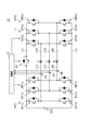
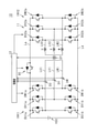
- FIG. 1 shows a drive device 10 that executes drive control of a rotary electric machine.
- the rotary electric machine is an open winding three-phase rotary electric machine having an open neutral point, and includes a U-phase winding U, a V-phase winding V, and a W-phase winding W.
- the drive device 10 includes a drive circuit 11, a control unit 12, and a DC power supply VDC.
- the drive circuit 11 includes a first inverter INV1, a second inverter INV2, a high potential connection line La, a low potential connection line Lb, a connection line switch SC, and phase current sensors DU, DV, and DW.
- the first inverter INV1 is a three-phase inverter, which is connected to a DC power supply VDC, and has an upper arm switch SU1a and a lower arm switch SU1b connected to one end of a U-phase winding U of a rotary electric machine, and a V-phase winding. It includes an upper arm switch SV1a and a lower arm switch SV1b connected to one end of V, and an upper arm switch SW1a and a lower arm switch SW1b connected to one end of the W-phase winding W.
- the second inverter INV2 is a three-phase inverter, and is connected to the upper arm switch SU2a and the lower arm switch SU2b connected to the other end of the U-phase winding U of the rotary electric machine, and to the other end of the V-phase winding V. It includes an upper arm switch SV2a and a lower arm switch SV2b, and an upper arm switch SW2a and a lower arm switch SW2b connected to the other end of the W-phase winding W.
- the high-potential connection line La is a wiring that connects the DC high-potential side of the first inverter INV1 and the DC high-potential side of the second inverter INV2.
- the low-potential connection line Lb connects the DC low-potential side of the first inverter INV1 and the DC low-potential side of the second inverter.
- the high potential side terminals of the upper arm switches SU1a, SV1a, SW1a of each phase are connected to the positive electrode terminals of the DC power supply VDC, and the low potential side terminals of the lower arm switches SU1b, SV1b, SW1b of each phase are It is connected to the negative electrode terminal of the DC power supply VDC.
- the upper arm switches SU1a, SV1a, SW1a and the lower arm switches SU1b, SV1b, SW1b are semiconductor switching elements, respectively.
- the high potential side terminals of the upper arm switches SU2a, SV2a, SW2a of each phase are connected to the high potential connection line La, and the low potential side terminals of the lower arm switches SU2b, SV2b, SW2b of each phase are low. It is connected to the potential connection line Lb.
- the upper arm switches SU2a, SV2a, SW2a and the lower arm switches SU2b, SV2b, SW2b are semiconductor switching elements, respectively.
- semiconductor switching element examples include MOSFETs (Metal-Oxide-Semicondustor Field-Effective Transistors), IGBTs (Insulated Gate Bipolar Transistors) having freewheeling diodes connected in antiparallel, and the like.
- MOSFETs Metal-Oxide-Semicondustor Field-Effective Transistors
- IGBTs Insulated Gate Bipolar Transistors
- the intermediate points between the upper arm switches SU1a, SV1a, SW1a and the lower arm switches SU1b, SV1b, SW1b of each phase are wound by the first phase connection lines LU1, LV1, LW1, respectively. It is connected to one end of U, V, W (one end not connected to the second inverter INV2).
- the intermediate points between the upper arm switches SU2a, SV2a, SW2a and the lower arm switches SU2b, SV2b, SW2b of each phase are wound by the second phase connection lines LU2, LV2, LW2, respectively.
- One current sensor is installed as each of the phase current sensors DU, DV, and DW on the first phase connection lines LU1, LV1, and LW1.
- connection line switch SC is provided on the high-potential connection line La, and conducts or cuts off the first inverter INV1 and the second inverter INV2 by conducting or cutting off the high-potential connection line La.
- the drive circuit 11 can be used as an H-bridge circuit, and the rotary electric machine can be driven by H.
- the drive circuit 11 When the connection line switch SC is in the open state (off state), the drive circuit 11 enables Y drive of the rotary electric machine. For example, by closing all the upper arm switches SU2a, SV2a, SW2a of the second inverter INV2 and opening all the lower arm switches SU2b, SV2b, SW2b, Y drive of the rotary electric machine becomes possible. .. That is, the U-phase winding U of the rotary electric machine, the V-phase winding V, and the W-phase winding W can be connected by a Y connection.
- the upper arm switches SU2a, SV2a, and SW2a correspond to the neutral point configuration switch constituting the neutral point of the Y connection (star-shaped connection).
- the control unit 12 includes a microcomputer including a CPU and various memories, and opens and closes each switch in the first inverter INV1 and the second inverter INV2 based on various detection information in the rotary electric machine and requests for power running drive and power generation. Energization control is performed by (on / off).
- the detection information of the rotary electric machine includes, for example, the rotation angle of the rotor (electric angle information) detected by an angle detector such as a resolver, the power supply voltage (inverter input voltage) detected by the voltage sensor, and the current sensor.
- the energizing current of each phase is included.
- the control unit 12 further controls the opening and closing of the connection line switch SC.
- the control unit 12 controls the connection line switch SC to be in the closed state when H is driven, and controls the connection line switch SC to be in the open state when Y is driven.
- the control unit 12 generates and outputs an operation signal for operating each switch of the first inverter INV1 and the second inverter INV2 and the connection line switch SC.
- the control unit 12 can control the connection line switch SC to the closed state and execute, for example, alternate PWM drive.
- the alternate PWM drive is an example of asymmetric switching control in which the first inverter INV1 and the second inverter INV2 are operated alternately.
- the control unit 12 controls the connection line switch SC in the open state, controls the upper arm switches SU2a, SV2a, SW2a of the second inverter INV2 in the closed state, and controls the second inverter INV2.
- the U-phase winding U, the V-phase winding V, and the W-phase winding W of the rotary electric machine are in a Y-connected state. ..
- Y connection is realized by connecting the winding terminals of the windings U, V, and W on the second inverter INV2 side via the upper arm switches SU2a, SV2a, and SW2a, respectively.
- the rotary electric machine can be Y-driven by forming a Y connection using the second inverter INV2 and executing PWM control or the like for the first inverter INV1.
- the upper arm switches SU2a, SV2a, and SW2a correspond to the neutral point configuration switch constituting the neutral point of the Y connection. Since the lower arm switches SU2b, SV2b, and SW2b do not form a neutral point, they correspond to a non-neutral point configuration switch.
- the U, V, and W phases of the rotary electric machine are symmetrically connected during Y drive, the current waveforms cancel each other out at a predetermined frequency component, and the instantaneous vector sum becomes zero. That is, when the rotary electric machine is driven in Y, the state in which the sum of the three phases is zero for the U, V, and W phases can be used.
- a predetermined frequency component in which the three-phase sum is in a zero state is referred to as a specific frequency component in the present specification.
- the following equation (1) is an equation showing the frequency function f (x) obtained by performing a Fourier series expansion on the current waveform of the phase current. It is known that the U, V, and W phases are in phase with each other in the third, ninth, and fifteenth-order components during the Y drive, so that the sum of the three phases is zero. That is, in a three-phase rotary electric machine, the sum of three phases becomes zero in the third, ninth, and fifteenth-order components, and the third, ninth, and fifteenth-order components can be used as specific frequency components.
- the U, V, and W phase currents cancel each other out at a specific frequency component during Y drive
- the U, V, and W phase currents also at the same specific frequency component during H drive.
- the phase currents do not cancel each other out. Therefore, when the total current, which is the total current of each phase, is calculated during the H drive of the rotary electric machine, the total current does not become zero.
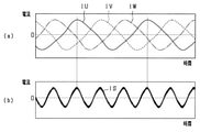
- FIG. 2A shows the phase currents IU, IV, and IW of the U, V, and W phases detected by the phase current sensors DU, DV, and DW when the rotary electric machine is driven to H.
- FIG. 2B shows the total current IS of the tertiary components of the phase currents IU, IV, and IW shown in FIG. 2A.
- the U, V, and W phase phase currents IU, IV, and IW detected by the phase current sensors DU, DV, and DW do not have the same phase and therefore do not cancel each other out. ..
- FIG. shows the phase currents IU, IV, and IW of the U, V, and W phases detected by the phase current sensors DU, DV, and DW.
- FIGS. 2A and 2B are comparative displays of current waveforms at the same time on the same time axis.
- control unit 12 is the total current, which is the total current wave in a specific frequency component, based on the phase current of each phase detected by the phase current sensors DU, DV, and DW when the rotary electric machine is driven to H. IS is calculated and this total current IS is monitored.
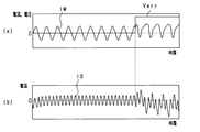
- FIGS. 3 (a) and 3 (b) show a comparative display of the phase current IW and the total current IS of the tertiary components of the phase currents IU, IV, and IW on the same time axis.
- FIG. 3A also illustrates the output voltage of the phase current sensor DW.
- the current waveform of the phase current IW detected by the phase current sensor DW changes from a normal sine waveform. It changes to an abnormal waveform.
- the current waveform of the phase current IW changes abnormally, as shown in FIG.
- the total current IS of the tertiary component also changes from a normal sine and cosine waveform to an abnormal waveform.
- the phase currents IU and IV when the current waveform changes from a normal sine and cosine waveform to an abnormal waveform, the total current of the tertiary components changes from a sine and cosine waveform to an abnormal waveform.
- the control unit 12 diagnoses the failure of the phase current sensors DU, DV, and DW by monitoring the change of the total current IS from a normal sine and cosine waveform to an abnormal waveform as shown in FIG. 3 (b). be able to. As shown in FIG. 3B, the amplitude of the current becomes large in the abnormal waveform. Therefore, the control unit 12 has, for example, at least one of the phase current sensors DU, DV, and DW when the cumulative total of the times when the total current IS exceeds the predetermined current threshold value exceeds the predetermined time threshold value. Can be configured to determine that has failed.
- the control unit 12 may be configured to diagnose a failure of the phase current sensors DU, DV, DW by monitoring a predetermined order component of the total current IS. This failure diagnosis will be described more specifically with reference to FIGS. 4 to 10.
- the vertical axis represents current and the horizontal axis represents time.
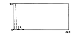
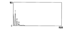
- the vertical axis indicates the current
- the horizontal axis indicates the frequency
- the numbers 1, 2, and 3 attached near the peak of the waveform are the primary component and the secondary component, respectively.
- Ingredients, tertiary ingredients are shown.
- FIG. 4 shows the phase detected by the phase current sensors DU, DV, and DW when the open winding three-phase rotary electric machine having the U, V, and W phases shown in FIG. 1 is driven by H and the alternate PWM drive is executed.
- the currents IU, IV and IW are shown.
- the phase currents IU, IV, and IW change from a normal sine wave to an abnormal waveform at time ct.
- FIG. 5 shows the results of frequency analysis of the phase currents IU, IV, and IW by fast Fourier transform (FFT: Fast Fourier transform) in the normal state before the time ct.
- FFT Fast Fourier transform
- the solid line, the broken line, and the alternate long and short dash line indicate the frequency analysis results of the phase currents IU, IV, and IW, respectively.
- the primary component is the largest, followed by the tertiary component.
- FIG. 6 shows the total current IS obtained from the phase currents IU, IV, and IW shown in FIG. 4 in the normal state before the time ct.
- FIG. 7 shows the result of frequency analysis of the total current IS shown in FIG. 6 by the fast Fourier transform. As shown in FIG. 7, in the total current IS in the normal state, the tertiary component is the largest.
- FIG. 8 shows the results of frequency analysis of the phase currents IU, IV, and IW by fast Fourier transform in the abnormal state after the time ct.
- the solid line, the broken line, and the alternate long and short dash line indicate the frequency analysis results of the phase currents IU, IV, and IW, respectively.
- the peak of the secondary component that did not appear in the normal state appears, which is larger than the peak of the tertiary component.
- FIG. 9 shows the total current IS obtained from the phase currents IU, IV, and IW shown in FIG. 4 in the abnormal state after the time ct.
- FIG. 10 shows the result of frequency analysis of the total current IS shown in FIG. 9 by fast Fourier transform.
- a peak of the secondary component that did not appear in the normal state appears.
- the peak of the frequency component having an even order in the total current IS (for example, the peak of the secondary component).
- control unit 12 frequency-analyzes the total current, and when the peak of the frequency component having an even order becomes a predetermined value or more, at least one of the phase current sensors DU, DV, and DW is used. It can be configured to determine that it has failed.
- FIG. 11 shows an example of a flowchart of the failure diagnosis process executed by the control unit 12. The process shown in FIG. 11 is repeatedly executed at a predetermined cycle.
- step S101 the phase currents IU, IV, and IW, which are the detected values of the current, are acquired from the phase current sensors DU, DV, and DW.
- step S102 the total current IS, which is the sum of the phase currents IU, IV, and IW, is calculated based on the phase currents IU, IV, and IW acquired in step S101.
- step S103 the process proceeds to step S103.
- step S103 it is determined whether or not the cumulative time T1 in which the total current IS calculated in step S102 exceeds the predetermined current threshold value X1 exceeds the predetermined time threshold value Y1. For example, when IS> X1 and T1> Y1, a positive determination is made in step S103, the process proceeds to step S104, and it is diagnosed that at least one of the phase current sensors DU, DV, and DW has failed. On the other hand, when IS ⁇ X1 or T1 ⁇ Y1, a negative determination is made in step S103, the process proceeds to step S105, and the phase current sensors DU, DV, and DW are diagnosed as having no failure. After steps S104 and S105, the process ends.
- one phase current sensor is provided for each of the plurality of first phase connection lines LU1, LV1, LW1 that connect the first inverter INV1 and the second inverter INV2 for each phase.
- DU, DV, DW are provided.
- the control unit 12 acquires the phase currents IU, IV, and IW, which are the values detected by the phase current sensors DU, DV, and DW, when the rotary electric machine is driven to H, and the phase currents IU, IV. , Calculate the total current IS, which is the total of IW.
- the control unit 12 among the phase current sensors DU, DV, and DW when the cumulative time T1 in which the total current IS exceeds the current threshold value X1 exceeds the time threshold value Y1. It is determined that at least one of the above has failed. Therefore, only one phase current sensor DU, DV, DW is installed for each U, V, W phase, and if any of the phase current sensors DU, DV, DW fails, this is diagnosed. It can be judged. In the drive circuit that executes H drive, the number of current sensors added for the failure diagnosis of the phase current sensor can be reduced, and the failure diagnosis of the current sensor and the reduction of the number of current sensors can be achieved at the same time.
- control unit 12 is configured to be able to execute failure diagnosis of the phase current sensors DU, DV, and DW even when the connection line switch SC is controlled to be in the open state in the drive circuit 11 to drive the rotary electric machine in Y. You may.
- the three-phase sum is zero in the specific frequency components exemplified by the third, ninth, and fifteenth-order components.
- one of the phase current sensors DU, DV, and DW is selected as an alternative monitoring sensor.
- the phase currents of other phase current sensors other than the alternative monitoring sensor are acquired, the sum of the detected values of the two phase current sensors at the specific frequency component is calculated, and the sum of the three phases becomes zero.
- the failure diagnosis of the phase current sensors DU, DV, and DW is performed by comparing the calculated value of the alternative monitoring sensor with the detected value actually measured by the alternative monitoring sensor.
- the control unit 12 selects the phase current sensor DW as an alternative monitoring sensor when driving the rotary electric machine in Y. Then, the phase currents IU and IV, which are the detected values of the phase current sensors DU and DV, are acquired. Since the sum of the three phases is zero in the specific frequency component, the calculated value IWc of the phase current of the W phase can be calculated from the phase current IU and the phase current IV. More specifically, the calculated value IWc can be calculated from the following equation (2).
- the control unit 12 compares the calculated value IWc with the detected value IWd of the phase current detected by the phase current sensor DW as an alternative monitoring sensor. Then, when the calculated value IWc and the detected value IWd substantially match, it is diagnosed that there is no failure in the phase current sensors DU, DV, and DW, and when the calculated value IWc and the detected value IWd deviate from each other, the phase current sensor DU. , DV, DW are diagnosed as having a failure.
- the drive device 10 uses one current sensor as a monitoring sensor DT, which can collectively detect all the currents flowing through the three first phase connection lines LU1, LV1, LW1. Further prepared.
- the control unit 12 acquires the phase currents IU, IV, IW detected by the phase current sensors DU, DV, DW and the total current IT detected by the monitoring sensor DT, and the phase currents IU, IV, IW and the total current.
- the failure diagnosis of the drive circuit 11 is executed based on the IT. Since the other configurations of the drive device 10 shown in FIG. 12 are the same as those of the drive device 10 shown in FIG. 1, the description thereof will be omitted.
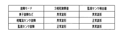
- the control unit 12 calculates the total current IS (three-phase sum calculation value) of the phase currents IU, IV, and IW, and uses the current waveform as the total current IT which is the detection value of the monitoring sensor DT. Compare with the current waveform of.
- the control unit 12 fails in an element (for example, a failure in the switching element constituting each of the inverters INV1 and INV2). ), Etc., and it is determined in the drive circuit 11 that the failure is not in the phase current sensors DU, DV, DW and the monitoring sensor DT, but in other parts.
- control unit 12 corresponds to the failure mode of the phase current sensor failure, and the phase current sensors DU, DV, DW. It is determined that at least one of them has failed.
- control unit 12 determines that the failure mode of the monitoring sensor failure corresponds to the failure mode and the monitoring sensor DT has failed.
- control unit 12 does not correspond to any of the failure modes shown in FIG. 13, that is, when both the total current IS and the total current IT have a normal sine and cosine waveform, the phase current sensors DU, DV, It is determined that all of the DW and the monitoring sensor DT are normal.
- FIG. 14 shows a flowchart of the failure diagnosis process executed by the control unit 12. The process shown in FIG. 11 is repeatedly executed at a predetermined cycle.
- step S201 the phase currents IU, IV, and IW, which are the detected values of the current, are acquired from the phase current sensors DU, DV, and DW, and the total current IT, which is the detected value of the current, is acquired from the monitoring sensor DT. do.
- step S202 the total current IS, which is the sum of the phase currents IU, IV, and IW, is calculated based on the phase currents IU, IV, and IW acquired in step S201. Then, the process proceeds to step S203.
- step S203 it is determined whether or not the cumulative time T1 in which the total current IS calculated in step S202 exceeds the predetermined current threshold value X1 exceeds the predetermined time threshold value Y1. For example, when IS> X1 and T1> Y1, a positive determination is made in step S203, and the process proceeds to step S204. On the other hand, when IS ⁇ X1 or T1 ⁇ Y1, a negative determination is made in step S203, and the process proceeds to step S207.
- step S204 it is determined whether or not the cumulative time T2 in which the total current IT calculated in step S201 exceeds the predetermined current threshold value X2 exceeds the predetermined time threshold value Y2. For example, when IT> X2 and T2> Y2, an affirmative determination is made in step S204, the process proceeds to step S205, it is diagnosed that there is an element failure (element failure mode), and the process is terminated. On the other hand, when IT ⁇ X2 or T2 ⁇ Y2, a negative determination is made in step S204, the process proceeds to step S206, and it is diagnosed that the phase current sensors DU, DV, and DW have a failure (phase current sensor failure mode). , End the process.
- step S207 as in step S204, it is determined whether or not the cumulative time T2 in which the total current IT exceeds the predetermined current threshold value X2 exceeds the predetermined time threshold value Y2.
- IT> X2 and T2> Y2 an affirmative determination is made in step S207, the process proceeds to step S208, the monitoring sensor DT is diagnosed as having a failure (in a monitoring sensor failure mode), and the process is terminated.
- IT ⁇ X2 or T2 ⁇ Y2 a negative determination is made in step S207, the process proceeds to step S209, a diagnosis of no failure is made, and the process ends.
- the monitoring sensor DT that can collectively detect all the currents flowing through the three first phase connection lines LU1, LV1, and LW1. Is further equipped.
- the control unit 12 acquires the total current IT, which is the detection value of the monitoring sensor DT, in addition to the phase currents IU, IV, and IW when the rotary electric machine is driven to H. Then, as shown in steps S203 to S209, the failure diagnosis is executed based on the total current IS, which is the total of the phase currents IU, IV, and IW, and the total current IT. Therefore, only by installing one phase current sensor DU, DV, DW for each U, V, W phase and one monitoring sensor DT, any one of the phase current sensors DU, DV, DW fails. If so, this can be determined by diagnosis. Furthermore, failure diagnosis of the monitoring sensor DT can also be performed. In the drive circuit that executes H drive, the number of current sensors added for the failure diagnosis of the phase current sensor can be reduced, and the failure diagnosis of the current sensor and the reduction of the number of current sensors can be achieved at the same time.
- any one of the phase current sensors DU, DV, and DW is further determined. It may be configured to identify if it has failed.
- the control unit 12 fails by comparing the current waveform of the total current IS with the current waveform of the total current IT, for example, with only one phase energized for each phase connection line of the U, V, and W phases. It is possible to identify the phase current sensor. When only one of the U, V, and W phases is energized, the total current IS and the total current IT substantially match for the phase in which the phase current sensor is normal.
- the U, V, and W phases are energized one by one in order, and the phase current sensors DU, DV are executed by performing a process to identify the phase in which the current waveform of the total current IS and the current waveform of the total current IT deviate from each other. , DW can be specified which one has failed.
- the drive device 10 is a drive device for a rotary electric machine mounted on a vehicle, it is possible to perform retractable running at the time of failure by identifying which of the phase current sensors DU, DV, and DW has failed. Become.
- the phase current sensors DU, DV, DW and the monitoring sensor DT are installed on the first phase connection lines LU1, LV1, LW1, but the second phase connection lines LU2, LV2. , May be connected to LW2.
- the connection line switch SC may be provided only on the low-potential connection line Lb, or may be provided on both the high-potential connection line La and the low-potential connection line Lb.
- the control unit 12 has a constant failure diagnosis mode in which the failure diagnosis is constantly executed and an emergency failure diagnosis mode in which the failure diagnosis is executed only under predetermined diagnostic conditions. May be configured to be switched based on the driving state of the rotary electric machine. For example, when the drive device 10 is a drive device for a rotary electric machine mounted on a vehicle, a failure diagnosis mode is always executed when the vehicle speed is high, and an emergency failure diagnosis mode is executed when the vehicle speed is low. You may switch to. More specifically, the failure diagnosis mode may be executed at all times when the vehicle speed is equal to or higher than the predetermined speed threshold value, and the emergency failure diagnosis mode may be executed when the vehicle speed is lower than the predetermined speed threshold value. ..
- the drive device 10 of a rotary electric machine is applied to a rotary electric machine having a plurality of windings corresponding to a plurality of phases.
- the drive device 10 includes a drive circuit 11 and a control unit 12.
- the drive circuit 11 includes a plurality of first phase connection lines LU1 and LV1 that connect the first inverter INV1 connected to the DC power supply VDC, the second inverter INV2, and the first inverter INV1 and the second inverter INV2 for each phase.
- LW1 each includes a phase current sensor DU, DV, DW, a high potential connection line La, and a low potential connection line Lb, and is configured to be able to execute H drive of a rotary electric machine.
- the control unit 12 is configured to be able to control the operation of the first inverter INV1 and the second inverter INV2 by controlling the opening and closing of the upper arm switch and the lower arm switch.
- the control unit 12 further calculates the total current IS, which is the total sum of the phase currents, based on the phase currents IU, IV, and IW detected by the phase current sensors DU, DV, and DW when the rotary electric machine is driven to H. Then, the failure diagnosis of the phase current sensors DU, DV, and DW is executed based on the total current IS. Since the total current IS does not become zero even in a specific frequency component during H drive, a failure of the phase current sensors DU, DV, and DW can be diagnosed by monitoring the total current IS.
- the drive device 10 only one phase current sensor DU, DV, DW flowing through the first phase connection line LU1, LV1, LW1 is installed for each phase, and any one of the phase current sensors DU, DV, DW is installed. If a failure occurs, this can be determined by diagnosis.
- the drive circuit 11 that executes H drive the number of current sensors added for failure diagnosis of the phase current sensors DU, DV, and DW can be reduced, and both the failure diagnosis of the current sensor and the reduction of the number of current sensors can be achieved. ..
- control unit 12 has at least one of the phase current sensors DU, DV, and DW when the cumulative current (T1) of the total current IS exceeds the predetermined current threshold value X1 exceeds the predetermined time threshold value Y1. It may be configured to determine that one of them has failed.
- control unit 12 performs frequency analysis of the total current IS, and when the peak of the frequency component having an even order becomes equal to or higher than a predetermined value, at least one of the phase current sensors DU, DV, and DW fails. It may be configured to determine.
- the drive circuit 11 may further include one current sensor as a monitoring sensor DT that can collectively detect all the currents flowing through the plurality of phase connection lines.
- the control unit 12 is configured to execute a failure diagnosis of the phase current sensor based on the current waveforms of the phase currents IU, IV, and IW and the current waveforms of the total current IT detected by the monitoring sensor DT. May be. Specifically, the control unit 12 may determine that the total current IS and the total current IT are normal when both have a normal sine and cosine waveform.
- both the total current IS and the total current IT do not have normal sine and cosine waveforms, it is determined that the parts of the drive circuit 11 other than the phase current sensors DU, DV, DW and the monitoring sensor DT have failed. You may. Further, when the total current IS is not a normal sine and cosine waveform and the total current IT is a normal sine and cosine waveform, it may be determined that at least one of the phase current sensors DU, DV, and DW has failed. .. Further, when the total current IS is a normal sine and cosine waveform and the total current IT is not a normal sine and cosine waveform, it may be determined that the monitoring sensor DT has failed.
- the control unit 12 When the drive circuit 11 includes the monitoring sensor DT, the control unit 12 further energizes only one phase for each phase connection line when it is determined that at least one of the phase current sensors DU, DV, and DW has failed. In the state, it may be configured to identify the failed phase current sensor by comparing the current waveform of the total current IS with the current waveform of the total current IT.
- the drive device 10 is a drive device for a rotary electric machine mounted on a vehicle, it is possible to perform retractable running at the time of failure by identifying which of the phase current sensors DU, DV, and DW has failed. Become.
- the control unit 12 has a constant failure diagnosis mode that constantly executes a failure diagnosis of the phase current sensors DU, DV, and DW, and an emergency failure diagnosis that executes a failure diagnosis of the phase current sensors DU, DV, and DW only under predetermined diagnostic conditions.
- the mode may be configured to be switchable based on the driving state of the rotary electric machine.
- the drive circuit 11 further includes a connection line switch SC that conducts or cuts off the first inverter INV1 and the second inverter INV2, and is configured to be able to switch between H drive and Y drive of the rotary electric machine.
- the control unit 12 selects one of the phase current sensors DU, DV, and DW as the alternative monitoring sensor when the rotary electric machine is driven in Y, and the phase current of the other phase current sensors other than the alternative monitoring sensor. It may be configured to perform failure diagnosis of the phase current sensors DU, DV, DW based on the sum and the current detected by the alternative monitoring sensor.
- the failure diagnosis can be executed by using the three phase current sensors DU, DV, and DW in both the H drive and the Y drive of the rotary electric machine.
- the number of current sensors added for failure diagnosis of the phase current sensors DU, DV, DW can be reduced, and the number of current sensor failure diagnosis and the number of current sensors can be reduced. Can be compatible with.
- the controls and methods thereof described in the present disclosure are realized by a dedicated computer provided by configuring a processor and memory programmed to perform one or more functions embodied by a computer program. May be done.
- the controls and methods thereof described in the present disclosure may be implemented by a dedicated computer provided by configuring the processor with one or more dedicated hardware logic circuits.
- the control unit and method thereof described in the present disclosure may be a combination of a processor and memory programmed to perform one or more functions and a processor configured by one or more hardware logic circuits. It may be realized by one or more dedicated computers configured.
- the computer program may be stored in a computer-readable non-transitional tangible recording medium as an instruction executed by the computer.
Landscapes
- Engineering & Computer Science (AREA)
- Power Engineering (AREA)
- Control Of Ac Motors In General (AREA)
- Inverter Devices (AREA)
Applications Claiming Priority (2)
| Application Number | Priority Date | Filing Date | Title |
|---|---|---|---|
| JP2020-125701 | 2020-07-22 | ||
| JP2020125701A JP7441135B2 (ja) | 2020-07-22 | 2020-07-22 | 回転電機の駆動装置 |
Publications (1)
| Publication Number | Publication Date |
|---|---|
| WO2022019083A1 true WO2022019083A1 (ja) | 2022-01-27 |
Family
ID=79729711
Family Applications (1)
| Application Number | Title | Priority Date | Filing Date |
|---|---|---|---|
| PCT/JP2021/024977 Ceased WO2022019083A1 (ja) | 2020-07-22 | 2021-07-01 | 回転電機の駆動装置 |
Country Status (2)
| Country | Link |
|---|---|
| JP (1) | JP7441135B2 (enExample) |
| WO (1) | WO2022019083A1 (enExample) |
Cited By (1)
| Publication number | Priority date | Publication date | Assignee | Title |
|---|---|---|---|---|
| CN118641952A (zh) * | 2024-08-15 | 2024-09-13 | 格陆博科技有限公司 | 一种三相电机电流传感器故障检测的方法 |
Families Citing this family (3)
| Publication number | Priority date | Publication date | Assignee | Title |
|---|---|---|---|---|
| JP2025152689A (ja) * | 2024-03-28 | 2025-10-10 | 株式会社デンソー | 電力変換装置及び駆動システム |
| JP2025152691A (ja) * | 2024-03-28 | 2025-10-10 | 株式会社デンソー | 電力変換装置及び駆動システム |
| JP2025152690A (ja) * | 2024-03-28 | 2025-10-10 | 株式会社デンソー | 電力変換装置及び駆動システム |
Citations (5)
| Publication number | Priority date | Publication date | Assignee | Title |
|---|---|---|---|---|
| JP2015202019A (ja) * | 2014-04-10 | 2015-11-12 | 日立オートモティブシステムズ株式会社 | 電動モータの制御装置 |
| JP2016201922A (ja) * | 2015-04-10 | 2016-12-01 | 東洋電機製造株式会社 | 交流電動機駆動システム及び交流電動機配線異常検出装置 |
| JP2017175747A (ja) * | 2016-03-23 | 2017-09-28 | 株式会社Soken | 電力変換装置 |
| JP2019013098A (ja) * | 2017-06-30 | 2019-01-24 | 株式会社デンソー | 電流センサの状態判定装置、車載回転電機システム |
| WO2019058668A1 (ja) * | 2017-09-21 | 2019-03-28 | 日本電産株式会社 | モータ制御方法、電力変換装置、モータモジュールおよび電動パワーステアリング装置 |
-
2020
- 2020-07-22 JP JP2020125701A patent/JP7441135B2/ja active Active
-
2021
- 2021-07-01 WO PCT/JP2021/024977 patent/WO2022019083A1/ja not_active Ceased
Patent Citations (5)
| Publication number | Priority date | Publication date | Assignee | Title |
|---|---|---|---|---|
| JP2015202019A (ja) * | 2014-04-10 | 2015-11-12 | 日立オートモティブシステムズ株式会社 | 電動モータの制御装置 |
| JP2016201922A (ja) * | 2015-04-10 | 2016-12-01 | 東洋電機製造株式会社 | 交流電動機駆動システム及び交流電動機配線異常検出装置 |
| JP2017175747A (ja) * | 2016-03-23 | 2017-09-28 | 株式会社Soken | 電力変換装置 |
| JP2019013098A (ja) * | 2017-06-30 | 2019-01-24 | 株式会社デンソー | 電流センサの状態判定装置、車載回転電機システム |
| WO2019058668A1 (ja) * | 2017-09-21 | 2019-03-28 | 日本電産株式会社 | モータ制御方法、電力変換装置、モータモジュールおよび電動パワーステアリング装置 |
Cited By (1)
| Publication number | Priority date | Publication date | Assignee | Title |
|---|---|---|---|---|
| CN118641952A (zh) * | 2024-08-15 | 2024-09-13 | 格陆博科技有限公司 | 一种三相电机电流传感器故障检测的方法 |
Also Published As
| Publication number | Publication date |
|---|---|
| JP7441135B2 (ja) | 2024-02-29 |
| JP2022021849A (ja) | 2022-02-03 |
Similar Documents
| Publication | Publication Date | Title |
|---|---|---|
| WO2022019083A1 (ja) | 回転電機の駆動装置 | |
| JP5465269B2 (ja) | 故障検出回路を備えた電動機駆動装置および電動機駆動装置の故障検出方法 | |
| JP2006081327A (ja) | インバータの故障検出装置 | |
| JPWO2016071949A1 (ja) | モータ制御装置、電動パワーステアリング装置およびインバータ系故障検出方法 | |
| KR20150122069A (ko) | 전동기 구동 장치 | |
| JPH11308704A (ja) | 電気車の制御装置及び制御方法 | |
| JP5584994B2 (ja) | インバータの故障診断装置 | |
| JP2010246327A (ja) | インバータの故障診断装置 | |
| WO2017122309A1 (ja) | 電動機制御装置 | |
| JP6652073B2 (ja) | モータ制御装置 | |
| JP2022021849A5 (enExample) | ||
| JP6197463B2 (ja) | インバータ制御交流モータの異常診断装置 | |
| JP6828515B2 (ja) | モータ制御装置 | |
| JP6890700B2 (ja) | 電力変換装置 | |
| JP2021191074A (ja) | インバータ制御装置 | |
| JP7006428B2 (ja) | モータ制御装置 | |
| JP7463989B2 (ja) | モータ制御装置 | |
| CN114245962B (zh) | 功率转换装置和功率转换装置的控制方法 | |
| JP2023146538A (ja) | 運転制御システム及び空気調和機、並びに運転制御方法、並びに運転制御プログラム | |
| CN113875143B (zh) | 功率转换装置和功率转换装置的控制方法 | |
| JP2025076044A (ja) | 電流センサの故障判定方法及び故障判定装置 | |
| US20250105724A1 (en) | Power conversion device and drive device | |
| JP2025121295A (ja) | インバータの異常検出方法及びインバータの異常検出システム | |
| WO2024057708A1 (ja) | 電力変換装置および駆動装置 | |
| JP2010239682A (ja) | 駆動装置 |
Legal Events
| Date | Code | Title | Description |
|---|---|---|---|
| 121 | Ep: the epo has been informed by wipo that ep was designated in this application |
Ref document number: 21847053 Country of ref document: EP Kind code of ref document: A1 |
|
| NENP | Non-entry into the national phase |
Ref country code: DE |
|
| 122 | Ep: pct application non-entry in european phase |
Ref document number: 21847053 Country of ref document: EP Kind code of ref document: A1 |