WO2022018910A1 - 分離膜複合体および分離方法 - Google Patents
分離膜複合体および分離方法 Download PDFInfo
- Publication number
- WO2022018910A1 WO2022018910A1 PCT/JP2021/014908 JP2021014908W WO2022018910A1 WO 2022018910 A1 WO2022018910 A1 WO 2022018910A1 JP 2021014908 W JP2021014908 W JP 2021014908W WO 2022018910 A1 WO2022018910 A1 WO 2022018910A1
- Authority
- WO
- WIPO (PCT)
- Prior art keywords
- separation membrane
- support
- separation
- zeolite
- membrane
- Prior art date
- Legal status (The legal status is an assumption and is not a legal conclusion. Google has not performed a legal analysis and makes no representation as to the accuracy of the status listed.)
- Ceased
Links
Images


Classifications
-
- B—PERFORMING OPERATIONS; TRANSPORTING
- B01—PHYSICAL OR CHEMICAL PROCESSES OR APPARATUS IN GENERAL
- B01D—SEPARATION
- B01D71/00—Semi-permeable membranes for separation processes or apparatus characterised by the material; Manufacturing processes specially adapted therefor
- B01D71/02—Inorganic material
- B01D71/028—Molecular sieves
- B01D71/0281—Zeolites
-
- B—PERFORMING OPERATIONS; TRANSPORTING
- B01—PHYSICAL OR CHEMICAL PROCESSES OR APPARATUS IN GENERAL
- B01D—SEPARATION
- B01D53/00—Separation of gases or vapours; Recovering vapours of volatile solvents from gases; Chemical or biological purification of waste gases, e.g. engine exhaust gases, smoke, fumes, flue gases, aerosols
- B01D53/22—Separation of gases or vapours; Recovering vapours of volatile solvents from gases; Chemical or biological purification of waste gases, e.g. engine exhaust gases, smoke, fumes, flue gases, aerosols by diffusion
- B01D53/228—Separation of gases or vapours; Recovering vapours of volatile solvents from gases; Chemical or biological purification of waste gases, e.g. engine exhaust gases, smoke, fumes, flue gases, aerosols by diffusion characterised by specific membranes
-
- B—PERFORMING OPERATIONS; TRANSPORTING
- B01—PHYSICAL OR CHEMICAL PROCESSES OR APPARATUS IN GENERAL
- B01D—SEPARATION
- B01D63/00—Apparatus in general for separation processes using semi-permeable membranes
- B01D63/06—Tubular membrane modules
- B01D63/066—Tubular membrane modules with a porous block having membrane coated passages
-
- B—PERFORMING OPERATIONS; TRANSPORTING
- B01—PHYSICAL OR CHEMICAL PROCESSES OR APPARATUS IN GENERAL
- B01D—SEPARATION
- B01D69/00—Semi-permeable membranes for separation processes or apparatus characterised by their form, structure or properties; Manufacturing processes specially adapted therefor
- B01D69/02—Semi-permeable membranes for separation processes or apparatus characterised by their form, structure or properties; Manufacturing processes specially adapted therefor characterised by their properties
-
- B—PERFORMING OPERATIONS; TRANSPORTING
- B01—PHYSICAL OR CHEMICAL PROCESSES OR APPARATUS IN GENERAL
- B01D—SEPARATION
- B01D69/00—Semi-permeable membranes for separation processes or apparatus characterised by their form, structure or properties; Manufacturing processes specially adapted therefor
- B01D69/10—Supported membranes; Membrane supports
- B01D69/106—Membranes in the pores of a support, e.g. polymerized in the pores or voids
-
- B—PERFORMING OPERATIONS; TRANSPORTING
- B01—PHYSICAL OR CHEMICAL PROCESSES OR APPARATUS IN GENERAL
- B01D—SEPARATION
- B01D69/00—Semi-permeable membranes for separation processes or apparatus characterised by their form, structure or properties; Manufacturing processes specially adapted therefor
- B01D69/10—Supported membranes; Membrane supports
- B01D69/108—Inorganic support material
-
- B—PERFORMING OPERATIONS; TRANSPORTING
- B01—PHYSICAL OR CHEMICAL PROCESSES OR APPARATUS IN GENERAL
- B01D—SEPARATION
- B01D69/00—Semi-permeable membranes for separation processes or apparatus characterised by their form, structure or properties; Manufacturing processes specially adapted therefor
- B01D69/12—Composite membranes; Ultra-thin membranes
-
- B—PERFORMING OPERATIONS; TRANSPORTING
- B01—PHYSICAL OR CHEMICAL PROCESSES OR APPARATUS IN GENERAL
- B01D—SEPARATION
- B01D71/00—Semi-permeable membranes for separation processes or apparatus characterised by the material; Manufacturing processes specially adapted therefor
- B01D71/02—Inorganic material
- B01D71/0215—Silicon carbide; Silicon nitride; Silicon oxycarbide
-
- B—PERFORMING OPERATIONS; TRANSPORTING
- B01—PHYSICAL OR CHEMICAL PROCESSES OR APPARATUS IN GENERAL
- B01D—SEPARATION
- B01D71/00—Semi-permeable membranes for separation processes or apparatus characterised by the material; Manufacturing processes specially adapted therefor
- B01D71/02—Inorganic material
- B01D71/024—Oxides
- B01D71/025—Aluminium oxide
-
- B—PERFORMING OPERATIONS; TRANSPORTING
- B01—PHYSICAL OR CHEMICAL PROCESSES OR APPARATUS IN GENERAL
- B01J—CHEMICAL OR PHYSICAL PROCESSES, e.g. CATALYSIS OR COLLOID CHEMISTRY; THEIR RELEVANT APPARATUS
- B01J20/00—Solid sorbent compositions or filter aid compositions; Sorbents for chromatography; Processes for preparing, regenerating or reactivating thereof
- B01J20/02—Solid sorbent compositions or filter aid compositions; Sorbents for chromatography; Processes for preparing, regenerating or reactivating thereof comprising inorganic material
- B01J20/06—Solid sorbent compositions or filter aid compositions; Sorbents for chromatography; Processes for preparing, regenerating or reactivating thereof comprising inorganic material comprising oxides or hydroxides of metals not provided for in group B01J20/04
- B01J20/08—Solid sorbent compositions or filter aid compositions; Sorbents for chromatography; Processes for preparing, regenerating or reactivating thereof comprising inorganic material comprising oxides or hydroxides of metals not provided for in group B01J20/04 comprising aluminium oxide or hydroxide; comprising bauxite
-
- B—PERFORMING OPERATIONS; TRANSPORTING
- B01—PHYSICAL OR CHEMICAL PROCESSES OR APPARATUS IN GENERAL
- B01J—CHEMICAL OR PHYSICAL PROCESSES, e.g. CATALYSIS OR COLLOID CHEMISTRY; THEIR RELEVANT APPARATUS
- B01J20/00—Solid sorbent compositions or filter aid compositions; Sorbents for chromatography; Processes for preparing, regenerating or reactivating thereof
- B01J20/02—Solid sorbent compositions or filter aid compositions; Sorbents for chromatography; Processes for preparing, regenerating or reactivating thereof comprising inorganic material
- B01J20/10—Solid sorbent compositions or filter aid compositions; Sorbents for chromatography; Processes for preparing, regenerating or reactivating thereof comprising inorganic material comprising silica or silicate
- B01J20/16—Alumino-silicates
- B01J20/18—Synthetic zeolitic molecular sieves
-
- B—PERFORMING OPERATIONS; TRANSPORTING
- B01—PHYSICAL OR CHEMICAL PROCESSES OR APPARATUS IN GENERAL
- B01J—CHEMICAL OR PHYSICAL PROCESSES, e.g. CATALYSIS OR COLLOID CHEMISTRY; THEIR RELEVANT APPARATUS
- B01J20/00—Solid sorbent compositions or filter aid compositions; Sorbents for chromatography; Processes for preparing, regenerating or reactivating thereof
- B01J20/28—Solid sorbent compositions or filter aid compositions; Sorbents for chromatography; Processes for preparing, regenerating or reactivating thereof characterised by their form or physical properties
- B01J20/28002—Solid sorbent compositions or filter aid compositions; Sorbents for chromatography; Processes for preparing, regenerating or reactivating thereof characterised by their form or physical properties characterised by their physical properties
- B01J20/28004—Sorbent size or size distribution, e.g. particle size
-
- B—PERFORMING OPERATIONS; TRANSPORTING
- B01—PHYSICAL OR CHEMICAL PROCESSES OR APPARATUS IN GENERAL
- B01J—CHEMICAL OR PHYSICAL PROCESSES, e.g. CATALYSIS OR COLLOID CHEMISTRY; THEIR RELEVANT APPARATUS
- B01J20/00—Solid sorbent compositions or filter aid compositions; Sorbents for chromatography; Processes for preparing, regenerating or reactivating thereof
- B01J20/28—Solid sorbent compositions or filter aid compositions; Sorbents for chromatography; Processes for preparing, regenerating or reactivating thereof characterised by their form or physical properties
- B01J20/28014—Solid sorbent compositions or filter aid compositions; Sorbents for chromatography; Processes for preparing, regenerating or reactivating thereof characterised by their form or physical properties characterised by their form
- B01J20/2803—Sorbents comprising a binder, e.g. for forming aggregated, agglomerated or granulated products
-
- B—PERFORMING OPERATIONS; TRANSPORTING
- B01—PHYSICAL OR CHEMICAL PROCESSES OR APPARATUS IN GENERAL
- B01J—CHEMICAL OR PHYSICAL PROCESSES, e.g. CATALYSIS OR COLLOID CHEMISTRY; THEIR RELEVANT APPARATUS
- B01J20/00—Solid sorbent compositions or filter aid compositions; Sorbents for chromatography; Processes for preparing, regenerating or reactivating thereof
- B01J20/28—Solid sorbent compositions or filter aid compositions; Sorbents for chromatography; Processes for preparing, regenerating or reactivating thereof characterised by their form or physical properties
- B01J20/28014—Solid sorbent compositions or filter aid compositions; Sorbents for chromatography; Processes for preparing, regenerating or reactivating thereof characterised by their form or physical properties characterised by their form
- B01J20/28033—Membrane, sheet, cloth, pad, lamellar or mat
- B01J20/28035—Membrane, sheet, cloth, pad, lamellar or mat with more than one layer, e.g. laminates, separated sheets
-
- B—PERFORMING OPERATIONS; TRANSPORTING
- B01—PHYSICAL OR CHEMICAL PROCESSES OR APPARATUS IN GENERAL
- B01J—CHEMICAL OR PHYSICAL PROCESSES, e.g. CATALYSIS OR COLLOID CHEMISTRY; THEIR RELEVANT APPARATUS
- B01J20/00—Solid sorbent compositions or filter aid compositions; Sorbents for chromatography; Processes for preparing, regenerating or reactivating thereof
- B01J20/28—Solid sorbent compositions or filter aid compositions; Sorbents for chromatography; Processes for preparing, regenerating or reactivating thereof characterised by their form or physical properties
- B01J20/28014—Solid sorbent compositions or filter aid compositions; Sorbents for chromatography; Processes for preparing, regenerating or reactivating thereof characterised by their form or physical properties characterised by their form
- B01J20/28042—Shaped bodies; Monolithic structures
- B01J20/28045—Honeycomb or cellular structures; Solid foams or sponges
-
- B—PERFORMING OPERATIONS; TRANSPORTING
- B01—PHYSICAL OR CHEMICAL PROCESSES OR APPARATUS IN GENERAL
- B01J—CHEMICAL OR PHYSICAL PROCESSES, e.g. CATALYSIS OR COLLOID CHEMISTRY; THEIR RELEVANT APPARATUS
- B01J20/00—Solid sorbent compositions or filter aid compositions; Sorbents for chromatography; Processes for preparing, regenerating or reactivating thereof
- B01J20/28—Solid sorbent compositions or filter aid compositions; Sorbents for chromatography; Processes for preparing, regenerating or reactivating thereof characterised by their form or physical properties
- B01J20/28054—Solid sorbent compositions or filter aid compositions; Sorbents for chromatography; Processes for preparing, regenerating or reactivating thereof characterised by their form or physical properties characterised by their surface properties or porosity
- B01J20/28078—Pore diameter
- B01J20/28085—Pore diameter being more than 50 nm, i.e. macropores
-
- B—PERFORMING OPERATIONS; TRANSPORTING
- B32—LAYERED PRODUCTS
- B32B—LAYERED PRODUCTS, i.e. PRODUCTS BUILT-UP OF STRATA OF FLAT OR NON-FLAT, e.g. CELLULAR OR HONEYCOMB, FORM
- B32B18/00—Layered products essentially comprising ceramics, e.g. refractory products
-
- C—CHEMISTRY; METALLURGY
- C04—CEMENTS; CONCRETE; ARTIFICIAL STONE; CERAMICS; REFRACTORIES
- C04B—LIME, MAGNESIA; SLAG; CEMENTS; COMPOSITIONS THEREOF, e.g. MORTARS, CONCRETE OR LIKE BUILDING MATERIALS; ARTIFICIAL STONE; CERAMICS; REFRACTORIES; TREATMENT OF NATURAL STONE
- C04B38/00—Porous mortars, concrete, artificial stone or ceramic ware; Preparation thereof
- C04B38/0006—Honeycomb structures
-
- C—CHEMISTRY; METALLURGY
- C07—ORGANIC CHEMISTRY
- C07C—ACYCLIC OR CARBOCYCLIC COMPOUNDS
- C07C7/00—Purification; Separation; Use of additives
- C07C7/12—Purification; Separation; Use of additives by adsorption, i.e. purification or separation of hydrocarbons with the aid of solids, e.g. with ion-exchangers
-
- C—CHEMISTRY; METALLURGY
- C07—ORGANIC CHEMISTRY
- C07C—ACYCLIC OR CARBOCYCLIC COMPOUNDS
- C07C7/00—Purification; Separation; Use of additives
- C07C7/144—Purification; Separation; Use of additives using membranes, e.g. selective permeation
-
- B—PERFORMING OPERATIONS; TRANSPORTING
- B01—PHYSICAL OR CHEMICAL PROCESSES OR APPARATUS IN GENERAL
- B01D—SEPARATION
- B01D2256/00—Main component in the product gas stream after treatment
- B01D2256/24—Hydrocarbons
- B01D2256/245—Methane
-
- B—PERFORMING OPERATIONS; TRANSPORTING
- B01—PHYSICAL OR CHEMICAL PROCESSES OR APPARATUS IN GENERAL
- B01D—SEPARATION
- B01D2257/00—Components to be removed
- B01D2257/50—Carbon oxides
- B01D2257/504—Carbon dioxide
-
- B—PERFORMING OPERATIONS; TRANSPORTING
- B01—PHYSICAL OR CHEMICAL PROCESSES OR APPARATUS IN GENERAL
- B01D—SEPARATION
- B01D2325/00—Details relating to properties of membranes
- B01D2325/02—Details relating to pores or porosity of the membranes
- B01D2325/0283—Pore size
-
- B—PERFORMING OPERATIONS; TRANSPORTING
- B01—PHYSICAL OR CHEMICAL PROCESSES OR APPARATUS IN GENERAL
- B01D—SEPARATION
- B01D2325/00—Details relating to properties of membranes
- B01D2325/02—Details relating to pores or porosity of the membranes
- B01D2325/0283—Pore size
- B01D2325/02833—Pore size more than 10 and up to 100 nm
-
- B—PERFORMING OPERATIONS; TRANSPORTING
- B01—PHYSICAL OR CHEMICAL PROCESSES OR APPARATUS IN GENERAL
- B01D—SEPARATION
- B01D2325/00—Details relating to properties of membranes
- B01D2325/04—Characteristic thickness
-
- C—CHEMISTRY; METALLURGY
- C04—CEMENTS; CONCRETE; ARTIFICIAL STONE; CERAMICS; REFRACTORIES
- C04B—LIME, MAGNESIA; SLAG; CEMENTS; COMPOSITIONS THEREOF, e.g. MORTARS, CONCRETE OR LIKE BUILDING MATERIALS; ARTIFICIAL STONE; CERAMICS; REFRACTORIES; TREATMENT OF NATURAL STONE
- C04B2111/00—Mortars, concrete or artificial stone or mixtures to prepare them, characterised by specific function, property or use
- C04B2111/00474—Uses not provided for elsewhere in C04B2111/00
- C04B2111/00793—Uses not provided for elsewhere in C04B2111/00 as filters or diaphragms
-
- C—CHEMISTRY; METALLURGY
- C04—CEMENTS; CONCRETE; ARTIFICIAL STONE; CERAMICS; REFRACTORIES
- C04B—LIME, MAGNESIA; SLAG; CEMENTS; COMPOSITIONS THEREOF, e.g. MORTARS, CONCRETE OR LIKE BUILDING MATERIALS; ARTIFICIAL STONE; CERAMICS; REFRACTORIES; TREATMENT OF NATURAL STONE
- C04B2111/00—Mortars, concrete or artificial stone or mixtures to prepare them, characterised by specific function, property or use
- C04B2111/00474—Uses not provided for elsewhere in C04B2111/00
- C04B2111/00793—Uses not provided for elsewhere in C04B2111/00 as filters or diaphragms
- C04B2111/00801—Membranes; Diaphragms
-
- C—CHEMISTRY; METALLURGY
- C04—CEMENTS; CONCRETE; ARTIFICIAL STONE; CERAMICS; REFRACTORIES
- C04B—LIME, MAGNESIA; SLAG; CEMENTS; COMPOSITIONS THEREOF, e.g. MORTARS, CONCRETE OR LIKE BUILDING MATERIALS; ARTIFICIAL STONE; CERAMICS; REFRACTORIES; TREATMENT OF NATURAL STONE
- C04B2237/00—Aspects relating to ceramic laminates or to joining of ceramic articles with other articles by heating
- C04B2237/30—Composition of layers of ceramic laminates or of ceramic or metallic articles to be joined by heating, e.g. Si substrates
- C04B2237/32—Ceramic
- C04B2237/34—Oxidic
- C04B2237/341—Silica or silicates
-
- C—CHEMISTRY; METALLURGY
- C04—CEMENTS; CONCRETE; ARTIFICIAL STONE; CERAMICS; REFRACTORIES
- C04B—LIME, MAGNESIA; SLAG; CEMENTS; COMPOSITIONS THEREOF, e.g. MORTARS, CONCRETE OR LIKE BUILDING MATERIALS; ARTIFICIAL STONE; CERAMICS; REFRACTORIES; TREATMENT OF NATURAL STONE
- C04B2237/00—Aspects relating to ceramic laminates or to joining of ceramic articles with other articles by heating
- C04B2237/30—Composition of layers of ceramic laminates or of ceramic or metallic articles to be joined by heating, e.g. Si substrates
- C04B2237/32—Ceramic
- C04B2237/34—Oxidic
- C04B2237/343—Alumina or aluminates
-
- C—CHEMISTRY; METALLURGY
- C04—CEMENTS; CONCRETE; ARTIFICIAL STONE; CERAMICS; REFRACTORIES
- C04B—LIME, MAGNESIA; SLAG; CEMENTS; COMPOSITIONS THEREOF, e.g. MORTARS, CONCRETE OR LIKE BUILDING MATERIALS; ARTIFICIAL STONE; CERAMICS; REFRACTORIES; TREATMENT OF NATURAL STONE
- C04B2237/00—Aspects relating to ceramic laminates or to joining of ceramic articles with other articles by heating
- C04B2237/30—Composition of layers of ceramic laminates or of ceramic or metallic articles to be joined by heating, e.g. Si substrates
- C04B2237/32—Ceramic
- C04B2237/34—Oxidic
- C04B2237/345—Refractory metal oxides
- C04B2237/346—Titania or titanates
-
- C—CHEMISTRY; METALLURGY
- C04—CEMENTS; CONCRETE; ARTIFICIAL STONE; CERAMICS; REFRACTORIES
- C04B—LIME, MAGNESIA; SLAG; CEMENTS; COMPOSITIONS THEREOF, e.g. MORTARS, CONCRETE OR LIKE BUILDING MATERIALS; ARTIFICIAL STONE; CERAMICS; REFRACTORIES; TREATMENT OF NATURAL STONE
- C04B2237/00—Aspects relating to ceramic laminates or to joining of ceramic articles with other articles by heating
- C04B2237/30—Composition of layers of ceramic laminates or of ceramic or metallic articles to be joined by heating, e.g. Si substrates
- C04B2237/32—Ceramic
- C04B2237/34—Oxidic
- C04B2237/345—Refractory metal oxides
- C04B2237/348—Zirconia, hafnia, zirconates or hafnates
-
- C—CHEMISTRY; METALLURGY
- C04—CEMENTS; CONCRETE; ARTIFICIAL STONE; CERAMICS; REFRACTORIES
- C04B—LIME, MAGNESIA; SLAG; CEMENTS; COMPOSITIONS THEREOF, e.g. MORTARS, CONCRETE OR LIKE BUILDING MATERIALS; ARTIFICIAL STONE; CERAMICS; REFRACTORIES; TREATMENT OF NATURAL STONE
- C04B2237/00—Aspects relating to ceramic laminates or to joining of ceramic articles with other articles by heating
- C04B2237/30—Composition of layers of ceramic laminates or of ceramic or metallic articles to be joined by heating, e.g. Si substrates
- C04B2237/32—Ceramic
- C04B2237/36—Non-oxidic
- C04B2237/365—Silicon carbide
-
- C—CHEMISTRY; METALLURGY
- C04—CEMENTS; CONCRETE; ARTIFICIAL STONE; CERAMICS; REFRACTORIES
- C04B—LIME, MAGNESIA; SLAG; CEMENTS; COMPOSITIONS THEREOF, e.g. MORTARS, CONCRETE OR LIKE BUILDING MATERIALS; ARTIFICIAL STONE; CERAMICS; REFRACTORIES; TREATMENT OF NATURAL STONE
- C04B2237/00—Aspects relating to ceramic laminates or to joining of ceramic articles with other articles by heating
- C04B2237/30—Composition of layers of ceramic laminates or of ceramic or metallic articles to be joined by heating, e.g. Si substrates
- C04B2237/32—Ceramic
- C04B2237/36—Non-oxidic
- C04B2237/368—Silicon nitride
-
- C—CHEMISTRY; METALLURGY
- C04—CEMENTS; CONCRETE; ARTIFICIAL STONE; CERAMICS; REFRACTORIES
- C04B—LIME, MAGNESIA; SLAG; CEMENTS; COMPOSITIONS THEREOF, e.g. MORTARS, CONCRETE OR LIKE BUILDING MATERIALS; ARTIFICIAL STONE; CERAMICS; REFRACTORIES; TREATMENT OF NATURAL STONE
- C04B2237/00—Aspects relating to ceramic laminates or to joining of ceramic articles with other articles by heating
- C04B2237/50—Processing aspects relating to ceramic laminates or to the joining of ceramic articles with other articles by heating
- C04B2237/58—Forming a gradient in composition or in properties across the laminate or the joined articles
Definitions
- the present invention relates to a separation membrane complex and a separation method using the separation membrane complex.
- the present application claims the benefit of priority from the Japanese patent application JP2020-124368 filed on 21 July 2020, and all disclosures of such application are incorporated herein by reference.
- Japanese Patent No. 5937569 (Reference 1), a honeycomb-shaped porous substrate having a plurality of cells, a porous intermediate layer arranged on the surface of the substrate in the cell, and a surface of the intermediate layer.
- a separation membrane structure comprising a zeolite membrane disposed in is disclosed.
- Japanese Unexamined Patent Publication No. 2017-80744 (Reference 2) discloses a separation membrane structure in which a zeolite membrane is formed on the outer peripheral surface of a cylindrical porous support by hydrothermal synthesis.
- the supply side surface area to which the separated mixed fluid (for example, mixed gas) is supplied is larger than the permeation side surface surface to which the fluid permeating the separation membrane structure flows out. If it is excessively small, the amount of fluid that permeates the separation membrane per unit time (that is, the permeation flow rate) decreases, which may reduce the efficiency of the separation process and increase the process cost.
- the thickness of the cylindrical base material may be reduced, and the strength of the separation membrane structure may be reduced.
- the structure-determining agent is used in the step of burning and removing the structure-determining agent from the zeolite membrane during the production of the separation membrane structure.
- the heating temperature must be raised in order to burn and remove the surface area, the removal of the structural defining agent is insufficient, or the material becomes non-uniform.
- cracks may occur in the zeolite membrane, and the separation performance (for example, separation ratio) of the zeolite membrane may deteriorate.
- the seed crystal adhering to the support is formed in the step of forming the zeolite membrane on the support by hydrothermal synthesis.
- the supply of the raw material solution may become non-uniform, and the zeolite membrane may grow non-uniformly, resulting in a decrease in permeation flow rate and separation performance.
- the amount of penetration of the zeolite membrane into the support surface becomes large and the permeation flow rate decreases, or the amount of penetration becomes small and the relaxation of the thermal expansion difference between the zeolite membrane and the support becomes insufficient, so that the zeolite membrane becomes insufficient.
- the above-mentioned ratio of the surface area on the supply side to the surface area on the transmission side has not been studied from various angles.
- the present invention is directed to a separation membrane composite, and provides a separation membrane composite in which a separation membrane has a large permeation flow rate and high separation performance, and the separation membrane is bonded on a support in a form in which a difference in thermal expansion is relaxed. I am aiming.
- the separation membrane complex includes a porous support and a separation membrane formed on the support and used for fluid separation.
- the supply side surface area which is the area of the region where the fluid is supplied on the surface of the separation membrane, is the area of the permeation side, which is the area of the surface of the support where the fluid that has passed through the separation membrane and the support flows out.
- the supply transmission area ratio divided by the surface area is 1.1 or more and 5.0 or less.
- the thickness of the separation membrane is 0.05 ⁇ m or more and 50 ⁇ m or less.
- the separation membrane is a zeolite membrane.
- the maximum number of membered rings of the zeolite constituting the zeolite membrane is 8 or less.
- the support includes a porous base material and a porous surface layer provided on the base material and having an average pore diameter smaller than that of the base material.
- the average pore diameter of the substrate is 1 ⁇ m or more and 50 ⁇ m or less, and the average pore diameter of the surface layer is 0.005 ⁇ m or more and 2 ⁇ m or less.
- the support is provided between the substrate and the surface layer and further comprises a porous intermediate layer having an average pore diameter smaller than that of the substrate.
- the base material and the surface layer contain Al 2 O 3 as a main material.
- the intermediate layer contains aggregate particles having Al 2 O 3 as a main material and an inorganic binder having TiO 2 as a main material and binding the aggregate particles.
- the support has a honeycomb shape in which a columnar main body extending in the longitudinal direction is provided with a plurality of cells, each of which is a through hole extending in the longitudinal direction.
- the area of the cross section perpendicular to the longitudinal direction of each of the plurality of cells is 2 mm 2 or more and 300 mm 2 or less.
- the plurality of cells are arranged in a grid pattern in the vertical direction and the horizontal direction on the end face of the support.
- the plurality of cells include a plurality of cell rows arranged in the vertical direction, with the cell group arranged in one column in the horizontal direction as the cell row.
- the plurality of cell rows are a single cell row in which both ends in the longitudinal direction are sealed, and two or more rows adjacent to one side in the vertical direction of the sealing cell row. It also includes a group of open cell rows having 6 or less rows of cells and both ends open in the longitudinal direction.
- the support is provided with a slit extending laterally through the sealing cell row from the outer surface of the support.
- the present invention is also directed to a separation method.
- the separation method comprises a) the step of preparing the above-mentioned separation membrane complex and b) supplying a mixed substance containing a plurality of types of gases or liquids to the separation membrane complex.
- the present invention comprises a step of separating a highly permeable substance in a mixed substance from other substances by permeating the separation membrane complex.
- the mixture is hydrogen, helium, nitrogen, oxygen, water, steam, carbon monoxide, carbon dioxide, nitrogen oxides, ammonia, sulfur oxides, hydrogen sulfide, sulfur fluoride, mercury, alcine, hydrogen cyanide, It contains one or more substances among carbonyl sulfide, hydrogens of C1 to C8, organic acids, alcohols, mercaptans, esters, ethers, ketones and aldehydes.
- FIG. 1 is a perspective view of the separation membrane complex 1 according to the embodiment of the present invention.
- FIG. 1 also shows a part of the internal structure of the separation membrane complex 1.
- FIG. 2 is a diagram showing an end face 114 of the separation membrane complex 1.
- FIG. 3 is an enlarged view showing a part of the vertical cross section of the separation membrane complex 1, and shows the vicinity of the cell 111, which will be described later.
- the separation membrane complex 1 is used when a specific substance is separated from a mixed substance in which a plurality of types of substances are mixed.
- the separation membrane complex 1 includes a porous support 11 and a zeolite membrane 12 (see FIG. 3) which is a separation membrane formed on the support 11. In FIG. 3, parallel diagonal lines are attached to the zeolite membrane 12.
- the zeolite membrane 12 does not include, at least, a membrane in which zeolite is formed on the surface of the support 11 and in which zeolite particles are simply dispersed in an organic membrane. Further, the zeolite membrane 12 may contain two or more types of zeolite having different structures and compositions.
- the separation membrane complex 1 may be provided with a separation membrane other than the zeolite membrane 12.
- the support 11 is a porous member that can permeate gas and liquid.
- the support 11 has a plurality of through holes 111 (hereinafter, referred to as: , Also referred to as "cell 111") is a honeycomb type support.
- a plurality of cells 111 are formed (that is, compartments) by the porous partition wall.
- the outer shape of the support 11 is substantially cylindrical.
- the cross section of each cell 111 perpendicular to the longitudinal direction is, for example, substantially circular.
- the diameter of the cell 111 is larger than the actual diameter, and the number of the cells 111 is smaller than the actual number.
- the plurality of cells 111 include a first cell 111a in which the zeolite membrane 12 is formed on the inner side surface, and a second cell 111b in which the zeolite membrane 12 is not formed on the inner side surface.
- the openings of the second cell 111b are sealed by the sealing member 115 on both end faces 114 in the longitudinal direction of the support 11.
- parallel diagonal lines are provided on the sealing member 115.
- the openings of the first cell 111a are not sealed and are open on both end faces 114 in the longitudinal direction of the support 11.
- the plurality of cells 111 are arranged in a grid pattern in the vertical direction (that is, the vertical direction in FIG. 2) and the horizontal direction on the end face 114 of the support 11.
- the cell 111 group arranged in one column in the horizontal direction (that is, the left-right direction in FIG. 2) is also referred to as a “cell row”.
- the plurality of cells 111 include a plurality of rows of cells arranged in the vertical direction.
- the cell row of each stage is composed of a plurality of first cells 111a or a plurality of second cells 111b.
- the cell row of the second cell 111b in the first row (hereinafter, also referred to as “second cell row 116b”) and the cell of the first cell 111a in the second row.
- Rows (hereinafter, also referred to as “first cell row 116a”) are arranged alternately adjacent to each other in the vertical direction.
- each first cell row 116a and each second cell row 116b are shown by being surrounded by a two-dot chain line (the same applies to FIG. 4 described later).
- the second cell row 116b is a sealing cell row in which both ends in the longitudinal direction are sealed.
- the plurality of second cells 111b of the second cell row 116b are communicated with each other by the slit 117, and communicate with the space outside the support 11 through the slit 117 extending to the outer surface 112 of the support 11.
- the slit 117 extends laterally through the second cell row 116b from the outer surface of the support 11.
- the first cell row 116a is an open cell row in which both ends in the longitudinal direction are open, and the two-tiered first cell 111a adjacent to one side in the vertical direction of the second cell row 116b is an open cell row group.
- the open cell row group is a plurality of first cell rows 116a sandwiched between two second cell rows 116b located closest to each other in the vertical direction.
- the number of stages of the first cell row 116a constituting the open cell row group is not limited to two, and may be changed in various ways. Preferably, the number of stages of the first cell row 116a constituting the open cell row group is 2 or more and 6 or less.
- FIG. 4 shows an example in which the number of stages of the first cell row 116a constituting the open cell row group is five.
- the length of the support 11 in the longitudinal direction is, for example, 100 mm to 2000 mm.
- the outer diameter of the support 11 is, for example, 5 mm to 300 mm.
- the inter-cell distance of adjacent cells 111 (that is, the thickness of the support 11 between the closest portions of adjacent cells 111) is, for example, 0.3 mm to 10 mm.
- the surface roughness (Ra) of the support 11 is, for example, 0.1 ⁇ m to 5.0 ⁇ m, preferably 0.2 ⁇ m to 2.0 ⁇ m.
- the area of the cross section perpendicular to the longitudinal direction of each cell 111 is, for example, 2 mm 2 or more and 300 mm 2 or less. As described above, when the cross section of each cell 111 is substantially circular, the diameter of the cross section is preferably 1.6 mm to 20 mm.
- the shapes and sizes of the support 11 and the cell 111 may be changed in various ways.
- the cross-sectional shape of the cell 111 may be a substantially elliptical shape or a substantially polygonal shape.
- the shape of the support 11 may be a plate shape, a tubular shape, a cylindrical shape, a columnar shape, a polygonal columnar shape, or the like.
- the thickness of the support 11 is, for example, 0.1 mm to 10 mm.
- the support 11 is formed of a ceramic sintered body.
- the ceramic sintered body selected as the material of the support 11 include alumina, silica, mullite, zirconia, titania, yttria, silicon nitride, silicon carbide and the like.
- the support 11 contains at least one of alumina, silica and mullite.
- the support 11 may contain an inorganic binder for bonding aggregate particles of the ceramic sintered body.
- an inorganic binder for bonding aggregate particles of the ceramic sintered body.
- the inorganic binder at least one of titania, mullite, easily sinterable alumina, silica, glass frit, clay mineral, and easily sinterable cordierite can be used.
- the support 11 has, for example, a multilayer structure in which a plurality of layers having different average pore diameters are laminated in the thickness direction in the vicinity of the inner side surface of each first cell 111a which is an open cell.
- the support 11 has a porous base material 31, a porous intermediate layer 32 formed on the base material 31, and a porous surface layer 33 formed on the intermediate layer 32. And. That is, the surface layer 33 is indirectly provided on the base material 31 via the intermediate layer 32. Further, the intermediate layer 32 is provided between the base material 31 and the surface layer 33.
- the surface layer 33 constitutes the inner surface of each first cell 111a of the support 11, and the zeolite membrane 12 is formed on the surface layer 33.
- the thickness of the surface layer 33 is, for example, 1 ⁇ m to 100 ⁇ m.
- the thickness of the intermediate layer 32 is, for example, 100 ⁇ m to 500 ⁇ m.
- the intermediate layer 32 and the surface layer 33 may or may not be provided on the inner surface of each second cell 111b. Further, the intermediate layer 32 and the surface layer 33 may or may not be provided on the outer surface 112 and the end surface 114 of the support 11.
- the average pore diameter of the surface layer 33 is smaller than the average pore diameter of the intermediate layer 32 and the average pore diameter of the base material 31. Further, the average pore diameter of the intermediate layer 32 is smaller than the average pore diameter of the base material 31.
- the average pore diameter of the base material 31 is, for example, 1 ⁇ m or more and 70 ⁇ m or less.
- the average pore diameter of the intermediate layer 32 is, for example, 0.1 ⁇ m or more and 10 ⁇ m or less.
- the average pore diameter of the surface layer 33 is, for example, 0.005 ⁇ m or more and 2 ⁇ m or less.
- the average pore diameter of the base material 31, the intermediate layer 32 and the surface layer 33 can be measured by, for example, a mercury porosimeter, a palm porosimeter or a nanopalm porosimeter.
- the porosity of the surface layer 33 is smaller than the porosity of the intermediate layer 32 and the porosity of the base material 31. Further, the porosity of the intermediate layer 32 is smaller than the porosity of the base material 31.
- the porosity of the substrate 31 is, for example, 25% or more and 50% or less.
- the porosity of the intermediate layer 32 is, for example, 15% or more and 70% or less.
- the porosity of the surface layer 33 is, for example, 15% or more and 70% or less.
- the porosity of the substrate 31, the intermediate layer 32 and the surface layer 33 can be measured by, for example, a mercury porosimeter, a palm porosimeter or a nanopalm porosimeter.
- the base material 31, the intermediate layer 32 and the surface layer 33 may be formed of the same material or may be made of different materials.
- the base material 31 and the surface layer 33 contain Al 2 O 3 as a main material.
- the intermediate layer 32 contains aggregate particles having Al 2 O 3 as a main material and an inorganic binder having TiO 2 as a main material.
- the aggregate particles of the base material 31, the intermediate layer 32, and the surface layer 33 are formed substantially only by Al 2 O 3.
- the base material 31 may contain an inorganic binder such as glass.
- the average particle size of the aggregate particles in the surface layer 33 is smaller than the average particle size of the aggregate particles in the intermediate layer 32. Further, the average particle size of the aggregate particles of the intermediate layer 32 is smaller than the average particle size of the aggregate particles of the base material 31.
- the average particle size of the aggregate particles of the base material 31, the intermediate layer 32 and the surface layer 33 can be measured by, for example, a laser diffraction method.
- the sealing member 115 can be formed of the same material as the base material 31, the intermediate layer 32, and the surface layer 33.
- the porosity of the sealing member 115 is, for example, 25% to 50%.
- the zeolite membrane 12 is formed on the inner side surface (that is, on the surface layer 33) of each first cell 111a, which is an open cell, and covers the inner side surface over substantially the entire surface.
- the zeolite membrane 12 is a porous membrane having fine pores.
- the zeolite membrane 12 can be used as a separation membrane that separates a specific substance from a mixed substance in which a plurality of types of substances are mixed by utilizing a molecular sieving action. In the zeolite membrane 12, other substances are less likely to permeate than the specific substance. In other words, the permeation rate of the other substance in the zeolite membrane 12 is lower than the permeation rate of the specific substance.
- the zeolite membrane 12 is not provided on the inner surface of each second cell 111b.
- the thickness of the zeolite membrane 12 is, for example, 0.05 ⁇ m or more and 50 ⁇ m or less, preferably 0.1 ⁇ m or more and 20 ⁇ m or less, and more preferably 0.5 ⁇ m or more and 10 ⁇ m or less. Thickening the zeolite membrane 12 improves the separation performance. Thinning the zeolite membrane 12 increases the permeation rate.
- the surface roughness (Ra) of the zeolite membrane 12 is, for example, 5 ⁇ m or less, preferably 2 ⁇ m or less, more preferably 1 ⁇ m or less, and further preferably 0.5 ⁇ m or less.
- the pore diameter of the zeolite membrane 12 is, for example, 0.2 nm to 1 nm. The pore diameter of the zeolite membrane 12 is smaller than the average pore diameter of the surface layer 33 of the support 11.
- the minor axis of the n-membered ring pores is defined as the pore diameter of the zeolite membrane 12.
- the minor axis of the n-membered ring pore having the largest minor axis is defined as the pore diameter of the zeolite membrane 12.
- the n-membered ring is a portion in which the number of oxygen atoms constituting the skeleton forming the pores is n, and each oxygen atom is bonded to a T atom described later to form a cyclic structure.
- the n-membered ring refers to a ring having a through hole (channel), and does not include a ring having no through hole.
- the n-membered ring pores are pores formed by the n-membered ring.
- the maximum number of membered rings of the zeolite contained in the above-mentioned zeolite membrane 12 is preferably 8 or less (for example, 6 or 8).
- the pore diameter of the zeolite membrane 12 is uniquely determined by the skeleton structure of the zeolite, and is described in "Database of Zeolite Structures" [online] of the International Zeolite Society, Internet ⁇ URL: http: // www. iza-structure. It can be obtained from the values disclosed in org / databases />.
- the type of zeolite constituting the zeolite membrane 12 is not particularly limited, but for example, AEI type, AEN type, AFN type, AFV type, AFX type, BEA type, CHA type, DDR type, ERI type, ETL type, FAU type ( X-type, Y-type), GIS-type, IHW-type, LEV-type, LTA-type, LTJ-type, MEL-type, MFI-type, MOR-type, PAU-type, RHO-type, SOD-type, SAT-type, etc. ..
- the zeolite is an 8-membered ring zeolite, for example, AEI type, AFN type, AFV type, AFX type, CHA type, DDR type, ERI type, ETL type, GIS type, IHW type, LEV type, LTA type, LTJ. Zeolites of type, RHO type, SAT type and the like may be used.
- the type of zeolite constituting the zeolite membrane 12 is a DDR type zeolite.
- the zeolite constituting the zeolite membrane 12 contains aluminum (Al), phosphorus (P) and a tetravalent element as T atoms (that is, atoms located at the center of the oxygen tetrahedron (TO 4) constituting the zeolite).
- Al aluminum
- P phosphorus
- TO 4 oxygen tetrahedron
- the tetravalent element is preferably one or more of silicon (Si), germanium (Ge), titanium (Ti) and zirconium (Zr), and more preferably one or more of Si and Ti. It is an element of, and particularly preferably Si.
- the zeolite constituting the zeolite membrane 12 is a SAPO-type zeolite in which the T atom is composed of Si, Al and P, and the T atom is composed of magnesium (Mg), Si, Al and P.
- a part of the T atom may be replaced with another element.
- the zeolite constituting the zeolite membrane 12 may contain an alkali metal.
- the alkali metal is, for example, sodium (Na) or potassium (K).
- Zeolite membrane 12 contains, for example, Si.
- the zeolite membrane 12 may contain, for example, any two or more of Si, Al and P.
- the zeolite membrane 12 may contain an alkali metal.
- the alkali metal is, for example, sodium (Na) or potassium (K).
- the Si / Al ratio in the zeolite membrane 12 is, for example, 1 or more and 100,000 or less.
- the Si / Al ratio is the molar ratio of the Si element to the Al element contained in the zeolite membrane 12.
- the Si / Al ratio is preferably 5 or more, more preferably 20 or more, still more preferably 100 or more, and the higher the ratio, the higher the heat resistance and acid resistance of the zeolite membrane 12, which is preferable.
- the Si / Al ratio in the zeolite membrane 12 can be adjusted by adjusting the mixing ratio of the Si source and the Al source in the raw material solution described later.
- the permeation rate (permeence) of CO 2 of the zeolite membrane 12 at 20 ° C to 400 ° C is, for example, 100 nmol / m 2. It is sec ⁇ Pa or more, and the CO 2 permeation rate / CH 4 leakage rate ratio (permeence ratio) of the zeolite membrane 12 at 20 ° C. to 400 ° C. is, for example, 25 or more.
- the permeence is, for example, 200 nmol / m 2 ⁇ sec ⁇ Pa or more, and the permeence ratio is, for example, 60 or more.
- a seed crystal used for forming the zeolite membrane 12 is generated and prepared (step S11).
- a raw material solution for seed crystals is prepared by dissolving or dispersing a raw material such as a Si source and a structure-defining agent (Structure-Directing Agent, hereinafter also referred to as “SDA”) in a solvent. ..
- SDA Structure-Directing Agent
- hydrothermal synthesis of the raw material solution is performed, and the obtained crystals are washed and dried to obtain a zeolite powder.
- the zeolite powder may be used as a seed crystal as it is, or a seed crystal may be obtained by processing the powder by pulverization or the like.
- a dispersion liquid in which the seed crystals are dispersed in a solvent for example, water or alcohol such as ethanol
- a solvent for example, water or alcohol such as ethanol
- the support 11 on the base so that the longitudinal direction is substantially parallel to the gravity direction and pouring the dispersion liquid through the upper opening of each first cell 111a, the seed crystals in the dispersion liquid are formed.
- Adheres to the inner surface of the first cell 111a (step S12).
- the dispersion liquid poured into the first cell 111a is discharged from the lower opening of the first cell 111a.
- step S12 is repeated a plurality of times (eg, 2 to 10 times).
- the support 11 is turned upside down in the middle of performing step S12 a plurality of times.
- a seed crystal adhering support in which the seed crystal is uniformly adhered to the inner surface of each first cell 111a is produced.
- the seed crystal may be attached to the inner surface of the first cell 111a by another method.
- the raw material solution is prepared, for example, by dissolving a Si source, SDA, or the like in a solvent.
- a solvent of the raw material solution for example, water or alcohol such as ethanol is used.
- the SDA contained in the raw material solution is, for example, an organic substance.
- the SDA for example, 1-adamantanamine can be used.
- the zeolite membrane 12 is formed on the inner surface of each first cell 111a of the support 11 (step S13).
- the temperature during hydrothermal synthesis is preferably 120 to 200 ° C, for example 160 ° C.
- the hydrothermal synthesis time is preferably 10 to 100 hours, for example, 30 hours.
- the support 11 and the zeolite membrane 12 are washed with pure water. After washing, the support 11 and the zeolite membrane 12 are dried at, for example, 80 ° C. After the support 11 and the zeolite membrane 12 are dried, the zeolite membrane 12 is heat-treated (that is, fired) to burn and remove the SDA in the zeolite membrane 12 almost completely, and the fine pores in the zeolite membrane 12 are formed. Penetrate. As a result, the above-mentioned separation membrane complex 1 is obtained (step S14).
- FIG. 6 is a cross-sectional view showing the separation device 2.
- FIG. 6 in order to facilitate the understanding of the figure, the cross section of the separation membrane complex 1 is simplified and shown conceptually.
- FIG. 7 is a diagram showing the flow of separation of the mixed substance by the separation device 2.
- a mixed substance containing a plurality of types of fluids that is, gas or liquid
- a highly permeable substance in the mixed substance is permeated through the separation membrane complex 1.
- Separates from the mixture may be performed for the purpose of extracting a highly permeable substance (hereinafter, also referred to as “highly permeable substance”) from the mixed substance, and may be performed for the purpose of extracting a substance having low permeability (hereinafter, “highly permeable substance”). It may be carried out for the purpose of concentrating (also referred to as "lowly permeable substance”).
- the mixed substance (that is, a mixed fluid) may be a mixed gas containing a plurality of types of gases, a mixed liquid containing a plurality of types of liquids, and a gas-liquid two-phase containing both a gas and a liquid. It may be a fluid.
- the mixed substances include, for example, hydrogen (H 2 ), helium (He), nitrogen (N 2 ), oxygen (O 2 ), water (H 2 O), water vapor (H 2 O), carbon monoxide (CO), and the like.
- Carbon dioxide (CO 2 ) nitrogen oxides, ammonia (NH 3 ), sulfur oxides, hydrogen sulfide (H 2 S), sulfur fluoride, mercury (Hg), arsine (AsH 3 ), hydrogen cyanide (HCN), sulfide
- the above-mentioned highly permeable substance is, for example, one or more of CO 2 , NH 3 and H 2 O, and is preferably H 2 O.
- Nitrogen oxides are compounds of nitrogen and oxygen.
- the above-mentioned nitrogen oxides include, for example, nitric oxide (NO), nitrogen dioxide (NO 2 ), nitrous oxide (also referred to as nitric oxide) (N 2 O), and dinitrogen trioxide (N 2 O 3). ), Nitric oxide (N 2 O 4 ), Nitric oxide (N 2 O 5 ) and other gases called NO X.
- Sulfur oxides are compounds of sulfur and oxygen.
- the above-mentioned sulfur oxide is, for example, a gas called SO X (sox) such as sulfur dioxide (SO 2 ) and sulfur trioxide (SO 3).
- Sulfur fluoride is a compound of fluorine and sulfur.
- the hydrocarbons of C1 to C8 are hydrocarbons having 1 or more carbon atoms and 8 or less carbon atoms.
- the hydrocarbons C3 to C8 may be any of a linear compound, a side chain compound and a cyclic compound.
- the hydrocarbons of C2 to C8 are saturated hydrocarbons (that is, those in which double bonds and triple bonds are not present in the molecule) and unsaturated hydrocarbons (that is, double bonds and / or triple bonds are molecules). It may be either of those present in it).
- Hydrocarbons of C1 to C4 are, for example, methane (CH 4 ), ethane (C 2 H 6 ), ethylene (C 2 H 4 ), propane (C 3 H 8 ), propylene (C 3 H 6 ), normal butane.
- the above-mentioned organic acid is a carboxylic acid, a sulfonic acid or the like.
- Carboxylic acids include, for example, formic acid (CH 2 O 2 ), acetic acid (C 2 H 4 O 2 ), oxalic acid (C 2 H 2 O 4 ), acrylic acid (C 3 H 4 O 2 ) or benzoic acid (C 3 H 4 O 2). 6 H 5 COOH) and the like.
- the sulfonic acid is, for example, ethane sulfonic acid (C 2 H 6 O 3 S) or the like.
- the organic acid may be a chain compound or a cyclic compound.
- the above-mentioned alcohols include, for example, methanol (CH 3 OH), ethanol (C 2 H 5 OH), isopropanol (2-propanol) (CH 3 CH (OH) CH 3 ), ethylene glycol (CH 2 (OH) CH 2). (OH)) or butanol (C 4 H 9 OH) or the like.
- Mercaptans are organic compounds having hydrogenated sulfur (SH) at the end, and are substances also called thiols or thioalcohols.
- the above-mentioned mercaptans are, for example, methyl mercaptan (CH 3 SH), ethyl mercaptan (C 2 H 5 SH), 1-propanethiol (C 3 H 7 SH) and the like.
- ester is, for example, formate ester or acetic acid ester.
- ether is, for example, dimethyl ether ((CH 3 ) 2 O), methyl ethyl ether (C 2 H 5 OCH 3 ) or diethyl ether ((C 2 H 5 ) 2 O).
- ketone is, for example, acetone ((CH 3 ) 2 CO), methyl ethyl ketone (C 2 H 5 COCH 3 ) or diethyl ketone ((C 2 H 5 ) 2 CO).
- aldehydes are, for example, acetaldehyde (CH 3 CHO), propionaldehyde (C 2 H 5 CHO) or butyraldehyde (butyraldehyde) (C 3 H 7 CHO) and the like.
- the mixed substance separated by the separating device 2 will be described as being a mixed gas containing a plurality of types of gases.
- the separation device 2 includes a separation membrane complex 1, a sealing unit 21, an outer cylinder 22, two sealing members 23, a supply unit 26, a first collection unit 27, and a second collection unit 28. ..
- the separation membrane composite 1, the sealing portion 21, and the sealing member 23 are housed in the outer cylinder 22.
- the supply unit 26, the first collection unit 27, and the second collection unit 28 are arranged outside the outer cylinder 22 and connected to the outer cylinder 22.
- parallel diagonal lines are drawn on the zeolite membrane 12 of the separation membrane complex 1.
- the sealing portions 21 are attached to both ends of the support 11 in the longitudinal direction (that is, the left-right direction in FIG. 6), and both end faces 114 in the longitudinal direction of the support 11 and outer surfaces in the vicinity of both end faces 114. It is a member that covers and seals a part of 112.
- the sealing portion 21 prevents the inflow and outflow of the liquid from the both end faces 114 of the support 11.
- the sealing portion 21 is, for example, a sealing layer formed of glass or resin.
- the sealing portion 21 is a glass seal having a thickness of 30 ⁇ m to 50 ⁇ m. The material and shape of the sealing portion 21 may be changed as appropriate.
- the sealing portion 21 is provided with a plurality of openings overlapping the plurality of first cells 111a of the support 11, both ends of each first cell 111a in the longitudinal direction are covered with the sealing portion 21. No. Therefore, it is possible for the fluid to flow in and out of the first cell 111a from both ends.
- the outer cylinder 22 is a substantially cylindrical tubular member.
- the outer cylinder 22 is made of, for example, stainless steel or carbon steel.
- the longitudinal direction of the outer cylinder 22 is substantially parallel to the longitudinal direction of the separation membrane complex 1.
- a supply port 221 is provided at one end of the outer cylinder 22 in the longitudinal direction (that is, the left end in FIG. 6), and a first discharge port 222 is provided at the other end.
- a second discharge port 223 is provided on the side surface of the outer cylinder 22.
- a supply unit 26 is connected to the supply port 221.
- the first collection unit 27 is connected to the first discharge port 222.
- the second collection unit 28 is connected to the second discharge port 223.
- the internal space of the outer cylinder 22 is a closed space isolated from the space around the outer cylinder 22.
- the two sealing members 23 are arranged over the entire circumference between the outer surface 112 of the separation membrane complex 1 and the inner surface of the outer cylinder 22 in the vicinity of both ends in the longitudinal direction of the separation membrane complex 1.
- Each sealing member 23 is a substantially annular member made of a material that is impermeable to gas and liquid.
- the seal member 23 is, for example, an O-ring made of a flexible resin.
- the sealing member 23 is in close contact with the outer surface 112 of the separation membrane complex 1 and the inner surface of the outer cylinder 22 over the entire circumference. In the example shown in FIG. 6, the sealing member 23 is in close contact with the outer surface of the sealing portion 21 and indirectly adheres to the outer surface of the separation membrane composite 1 via the sealing portion 21.
- the space between the sealing member 23 and the outer surface 112 of the separation membrane complex 1 and the space between the sealing member 23 and the inner surface of the outer cylinder 22 are sealed, and gas and liquid pass through almost or completely. It is impossible.
- the supply unit 26 supplies the mixed gas to the internal space of the outer cylinder 22 via the supply port 221.
- the supply unit 26 includes, for example, a pressure feeding mechanism such as a blower or a pump that pumps the mixed gas toward the outer cylinder 22.
- the pressure feeding mechanism includes, for example, a temperature control unit and a pressure control unit that adjust the temperature and pressure of the mixed gas supplied to the outer cylinder 22, respectively.
- the first recovery unit 27 and the second recovery unit 28 include, for example, a storage container for storing the gas derived from the outer cylinder 22, or a blower or a pump for transferring the gas.
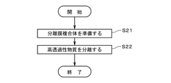
- the separation membrane complex 1 is prepared (FIG. 7: step S21). Specifically, the separation membrane complex 1 is attached to the inside of the outer cylinder 22. Subsequently, the supply unit 26 causes a mixed gas containing a plurality of types of gases having different permeability to the zeolite membrane 12 to be inside the outer cylinder 22 (specifically, a separation membrane composite) as shown by an arrow 251. (To the space on the left side of the end face 114 on the left side of 1). For example, the main components of the mixed gas are CO 2 and CH 4 . The mixed gas may contain a gas other than CO 2 and CH 4.
- the pressure (that is, the introduction pressure) of the mixed gas supplied from the supply unit 26 to the inside of the outer cylinder 22 is, for example, 0.1 MPa to 20.0 MPa.
- the temperature of the mixed gas supplied from the supply unit 26 is, for example, 10 ° C to 250 ° C.
- the mixed gas supplied from the supply unit 26 to the outer cylinder 22 flows into each first cell 111a of the separation membrane complex 1.
- the highly permeable substance which is a highly permeable gas in the mixed gas, permeates the zeolite membrane 12 and the support 11 from the first cell 111a, and the outer surface of the separation membrane composite 1 From 112, it is derived to the separation space 220 around the separation membrane complex 1.
- the separation space 220 is a substantially cylindrical space located on the radial outer side of the outer surface 112 of the separation membrane complex 1.
- the highly permeable substance that has passed through the zeolite membrane 12 and the support 11 from the first cell 111a and has flowed into the second cell 111b is the separation membrane composite 1 via the slit 117 as shown by the arrow 252b. It is guided to the outer surface 112 of the above and is led out to the separation space 220.
- the highly permeable substance that has flowed from the first cell 111a into the second cell 111b may pass through the support 11 and be led out to the separation space 220 without passing through the slit 117.
- the highly permeable substance permeates the zeolite membrane 12 and is led out to the separation space 220, so that the highly permeable substance (for example, CO 2 ) is a gas having low permeability in the mixed gas. It is separated from other substances such as poorly permeable substances (eg CH 4) (step S22).
- the separation membrane composite 1 since the end face 114 of the support 11 is covered with the sealing portion 21, the mixed gas containing the low-permeability substance enters the inside of the support 11 via the end face 114. It is prevented or suppressed from entering the separation space 220 without penetrating the zeolite membrane 12.
- the gas derived from the outer surface 112 of the separation membrane complex 1 (hereinafter referred to as “permeate”) is secondly recovered via the second discharge port 223 as shown by the arrow 253 in FIG. It is guided to the part 28 and collected.
- the permeable substance may contain a low permeable substance that has penetrated the zeolite membrane 12 in addition to the above-mentioned highly permeable substance.
- the gas excluding the substance that has permeated through the zeolite membrane 12 and the support 11 (hereinafter, referred to as “non-permeable substance”) is via the first discharge port 222 as shown by the arrow 254. It is guided to the first collection unit 27 and collected.
- the non-permeable substance may contain a highly permeable substance that has not penetrated the zeolite membrane 12 in addition to the above-mentioned low permeable substance.
- the non-permeable substance recovered by the first recovery unit 27 may be circulated to the supply unit 26 and supplied again into the outer cylinder 22, for example.
- the supply side surface area Ss is the total surface area of the zeolite membranes 12 formed on the inner side surfaces of the plurality of first cells 111a.
- the supply side surface area Ss is the total area of the exposed surfaces of the zeolite membrane 12 exposed in the first cell 111a.
- a part of the zeolite membrane 12 (for example, a region near the longitudinal end of the separation membrane composite 1) is covered with another structure such as a sealing portion 21, and the part of the region is covered with the fluid. Is not supplied, the surface area of the region is not included in the supply side surface area Ss.
- the permeation side surface area St is the total surface area of the outer surface 112 of the support 11, the inner surface of the plurality of slits 117, and the inner surface of the plurality of second cells 111b. Since both end faces 114 in the longitudinal direction of the support 11 are covered with the sealing portion 21 and the fluid that has passed through the zeolite membrane 12 and the support 11 does not flow out, the surface area of the end face 114 is included in the surface area St on the permeation side. I can't.
- a part of the outer surface 112 of the support 11, the inner surface of the plurality of slits 117, and the inner surface of the plurality of second cells 111b is covered with another structure such as the sealing portion 21. If the fluid does not flow out of the partial region, the surface area of the region is not included in the permeation side surface area St. For example, since the region near both ends of the outer surface 112 of the support 11 in the longitudinal direction is covered by the sealing portion 21, the area of the region is not included in the permeation side surface area St. Further, since the region near both ends of the inner surface of the inner surface of the second cell 111b in the longitudinal direction is covered with the sealing member 115, the area of the region is not included in the permeation side surface area St.
- the permeation side surface area St is the outer surface 112 of the support 11 (however, however). , Excluding the area covered by the sealing portion 21).
- the supply transmission area ratio is 1.1 or more and 5.0 or less.
- the supply transmission area ratio is preferably 2.0 or more, and more preferably 3.0 or more.
- the supply transmission area ratio is preferably 4.5 or less, and more preferably 4.0 or less.
- the processing cost may increase.
- the separation membrane composite 1 by setting the supply permeation area ratio to 1.1 or more, the amount of the mixed gas supplied to the zeolite membrane 12 per unit time is increased, and the zeolite membrane 12 is permeated. It is possible to increase the permeation flow rate of the highly permeable substance. As a result, the efficiency of the separation process of the mixed gas is improved, and the increase in the processing cost required for the separation process is suppressed.
- the zeolite membrane is burned and removed from the zeolite membrane 12 during the production of the separation membrane composite 1 (FIG. 5: step S14).
- the amount of SDA discharged from the front surface of 12 that is, the amount of vaporized SDA discharged
- the back surface side of the zeolite membrane 12 is the support 11 of the zeolite membrane 12. It is the joint surface side to be joined.
- the time required for removing the SDA becomes non-uniform in the thickness direction of the zeolite membrane 12, and a part of the zeolite membrane 12 is formed.
- SDA may remain, resulting in insufficient removal of SDA or non-uniform removal.
- the separation performance for example, separation ratio
- the yield may decrease.
- the separation membrane complex 1 the difference in SDA emissions between the front surface side and the back surface side of the zeolite membrane 12 is reduced by setting the supply permeation area ratio to 1.1 or more and 5.0 or less. Can be done. As a result, insufficient removal of SDA and non-uniform removal of SDA in the zeolite membrane 12 can be prevented or suppressed. In addition, damage such as cracks due to excessive heating of the zeolite membrane 12 can be prevented or suppressed. Therefore, the separation performance of the separation membrane complex 1 can be improved. Further, in the production of the separation membrane complex 1, the yield can be improved.
- step S13 the step of forming the zeolite membrane 12 on the support 11 by hydrothermal synthesis during the production of the separation membrane composite 1.
- raw material supply amount the amount of raw material supplied from the raw material solution that has passed through the partition wall of the first cell 111a to the seed crystal adhering to the support 11. Also called, but it is out of the proper range.
- raw material supply amount the amount of raw material supplied from the raw material solution that has permeated the partition wall may be excessively large, and the amount of penetration of the zeolite membrane 12 into the support 11 may be excessively large.
- the permeation flow rate of the highly permeable substance in the separation membrane complex 1 may decrease.
- the supply permeation area ratio is excessively large, the amount of raw material supplied from the raw material solution that has permeated the partition wall may be excessively small, and the amount of penetration of the zeolite membrane 12 into the support 11 may be excessively small.
- the relaxation of the difference in thermal expansion between the zeolite membrane 12 and the support 11 becomes insufficient, and cracks may occur in the zeolite membrane 12 in the step of burning and removing SDA (step S14), resulting in deterioration of separation performance. ..
- the amount of raw material supplied to the seed crystal on the back surface side of the zeolite membrane 12 to be formed is appropriate.
- the amount of penetration of the zeolite membrane 12 into the support 11 can be set in a suitable range. Therefore, the permeation flow rate in the zeolite membrane 12 can be increased, and the zeolite membrane 12 can be bonded to the support 11 in a form in which the difference in thermal expansion is relaxed.
- the above-mentioned supply transmission area ratio can be adjusted by various methods. For example, by changing the number of stages of the first cell row 116a constituting the open cell row group, the supply transmission area ratio can be changed relatively significantly. Further, the supply transmission area ratio can be reduced by setting the second cell row 116b, which is the sealing cell row located between the two open cell row groups, to two or more stages. Alternatively, in the first cell row 116a, the supply transmission area ratio can be changed by changing the cell-to-cell distance and changing the number of the first cells 111a. Similarly, in the second cell row 116b, the supply transmission area ratio can be changed by changing the cell-to-cell distance and changing the number of the second cells 111b. It is also possible to change the supply transmission area ratio by changing the cell cross-sectional area of the first cell 111a and / or the second cell 111b. It is also possible to change the supply transmission area ratio by changing the length of the slit 117.
- Example 1 to 16 the shape of the support 11, the pore diameter of the surface layer 33, the type and thickness of the zeolite membrane 12, and the supply permeation area ratio are variously changed, and the CO 2 permeation flow rate in the separation membrane composite 1 is changed. And the separation coefficient were measured as the characteristics of the separation membrane complex 1. The same applies to Comparative Examples 1 to 11.
- the CO 2 permeation flow rate in Tables 2 to 8 is measured by the following method, and then compared with other examples using the CO 2 permeation flow rate of the example at the top of each table as a reference (1.00).
- the CO 2 permeation flow rate of the example was relativized (that is, divided by the CO 2 permeation flow rate of the uppermost example).
- the measurement of CO 2 permeation flow rate first, measuring supplying CO 2 to the separation membrane complex 1 by using the above separating apparatus 2, the flow rate of the CO 2 passing through the zeolite membrane 12 and the support member 11 by a mass flow meter did. Then, the above-mentioned CO 2 permeation flow rate (L / (min ⁇ m 2 )) was obtained by dividing the flow rate by the surface area of the zeolite membrane 12.
- the separation coefficients in Tables 2 to 8 are indexes indicating the separation performance of the zeolite membrane 12, and the larger the separation coefficient, the higher the separation performance.
- the separation coefficient is measured by the following method, and then the separation coefficients of the other examples and comparative examples are relativized (that is, using the separation coefficient of the example at the top of each table as a reference (1.00)). , Divided by the separation factor of the example in the uppermost row).
- a mixed gas at 25 ° C. containing 50% by volume CO 2 and 50% by volume CH 4 is applied to a mixed gas at a total pressure of 0.4 MPa (that is, CO 2 and CO 2 and 50% by volume).
- the separation membrane composite 1 It was supplied to the separation membrane composite 1 at a partial pressure of 0.2 MPa for each of CH 4. Then, the flow rate of the gas permeating through the zeolite membrane 12 and the support 11 was measured with a mass flow meter. Further, the component analysis of the gas permeated through the zeolite membrane 12 and the support 11 was performed using a gas chromatograph. Then, the separation coefficient was obtained from the permeation rate ratio of CO 2 / CH 4 (that is, the ratio of the unit differential pressure, the unit area and the permeation flow rate per unit time).
- the separation coefficients in Tables 2 to 8 are also indicators of whether or not cracks have occurred in the zeolite membrane 12. Specifically, the zeolite membrane 12 whose thermal expansion difference with respect to the support 11 is insufficiently relaxed causes relatively large cracks due to the thermal expansion difference with the support 11 in the SDA combustion removal step in step S14 described above. Therefore, the separation coefficient decreases.
- the structure of the support 11 is a honeycomb shape, and the number of stages of the open cell row group (that is, the number of stages of the first cell row 116a constituting the open cell row group) is 2 as in the example shown in FIG. It is a step.
- the average pore diameter of the surface layer 33 of the support 11 is 0.05 ⁇ m.
- the type of zeolite constituting the zeolite membrane 12 is a DDR type (8-membered ring), and the thickness of the zeolite membrane 12 is 0.5 ⁇ m.
- the supply transmission area ratio of the separation membrane complex 1 is 1.50.
- Example 2 is the same as Example 1 except that the number of stages of the open cell row group is 5 (see FIG. 4) and the supply transmission area ratio is 4.29.
- Example 3 is the same as Example 1 except that the average pore diameter of the surface layer 33 is 0.005 ⁇ m.
- Example 4 is the same as Example 1 except that the thickness of the zeolite membrane 12 is 1 ⁇ m.
- Example 5 is the same as Example 4 except that the supply transmission area ratio is 2.00.
- Example 6 is the same as Example 4 except that the number of stages of the open cell row group is 3 and the supply transmission area ratio is 2.75.
- Example 7 is the same as Example 4 except that the number of stages of the open cell row group is 4 and the supply transmission area ratio is 3.29.
- Example 8 is the same as Example 4 except that the number of stages of the open cell row group is 5 (see FIG. 4) and the supply transmission area ratio is 4.00.
- Example 9 is the same as Example 8 except that the supply transmission area ratio is 4.29.
- Example 10 is the same as Example 9 except that the type of zeolite membrane 12 is AEI type (8-membered ring).
- Example 11 is the same as Example 9 except that the type of zeolite membrane 12 is MFI type (10-membered ring).
- Example 12 is the same as Example 4 except that the number of stages of the open cell row group is 6 and the supply transmission area ratio is 4.80.
- Example 13 is the same as Example 1 except that the average pore diameter of the surface layer 33 is 1.2 ⁇ m and the thickness of the zeolite membrane 12 is 38 ⁇ m.
- Example 14 is the same as Example 13 except that the number of stages of the open cell row group is 5 (see FIG. 4) and the supply transmission area ratio is 4.29.
- the structure of the support 11 is a cylindrical tube, and the average pore diameter of the surface layer 33 of the support 11 is 0.05 ⁇ m.
- the type of zeolite constituting the zeolite membrane 12 is a DDR type (8-membered ring), and the thickness of the zeolite membrane 12 is 1 ⁇ m.
- the supply transmission area ratio of the separation membrane complex 1 is 1.30.
- Example 16 is the same as Example 15 except that the supply transmission area ratio is 4.00.
- Comparative Example 1 is the same as that of Example 1 except that the number of stages of the open cell row group is 1 and the supply transmission area ratio is 1.07.
- Comparative Example 2 is the same as that of Example 1 except that the number of stages of the open cell row group is 6 and the supply transmission area ratio is 5.40.
- Comparative Example 3 is the same as Example 4 except that the number of stages of the open cell row group is 1 and the supply transmission area ratio is 1.07.
- Comparative Example 4 is the same as Example 4 except that the number of stages of the open cell row group is 6 and the supply transmission area ratio is 5.40.
- Comparative Example 5 is the same as Comparative Example 4 except that the average pore diameter of the surface layer 33 is 0.01 ⁇ m.
- Comparative Example 6 is the same as Comparative Example 4 except that the type of zeolite membrane 12 is AEI type (8-membered ring).
- Comparative Example 7 is the same as Comparative Example 4 except that the type of zeolite membrane 12 is MFI type (10-membered ring).
- Comparative Example 8 is the same as Comparative Example 3 except that the average pore diameter of the surface layer 33 is 1.2 ⁇ m and the thickness of the zeolite membrane 12 is 38 ⁇ m.
- Comparative Example 9 is the same as Comparative Example 8 except that the number of stages of the open cell row group is 6 and the supply transmission area ratio is 5.40.
- Comparative Example 10 is the same as Example 15 except that the supply transmission area ratio is 1.08.
- Comparative Example 11 is the same as Example 15 except that the supply transmission area ratio is 6.00.
- the supply permeation area ratio of Examples 1 and 2 is 1.50.
- the supply transmission area ratio of Comparative Example 1 is 1.07 (that is, less than 1.1), while it is ⁇ 4.29 (that is, 1.1 or more and 5.0 or less), which is the same as that of Comparative Example 2.
- the feed transmission area ratio is 5.40 (ie, greater than 5.0).
- the structure (honeycomb shape) of the support 11, the average pore diameter of the surface layer 33, and the type and thickness (0.5 ⁇ m) of the zeolite membrane 12 are the same. ..
- Example 1 In Examples 1 and 2 in which the supply permeation area ratio is 1.1 or more and 5.0 or less, the ratio of the CO 2 permeation flow rate (that is, the ratio based on Example 1) is 1.00 to 1.14. Yes, the ratio of separation coefficients (that is, the ratio based on Example 1) was 1.00 to 1.19. In Example 1, the CO 2 permeation flow rate and the separation coefficient were 458 L / (min ⁇ m 2 ) and 151, respectively. On the other hand, in Comparative Example 1 in which the supply permeation area ratio was less than 1.1, the ratio of the CO 2 permeation flow rate was 0.33, and the CO 2 permeation flow rate was smaller than that in Examples 1 and 2.
- Comparative Example 1 since the ratio of the separation coefficient is as small as 0.28, the separation performance is lower than that of Examples 1 and 2. In Comparative Example 2 in which the supply transmission area ratio is larger than 5.0, the separation coefficient ratio is as small as 0.05, so that the separation performance is lower than in Examples 1 and 2. Further, in Comparative Example 2, since the zeolite membrane 12 was cracked during the manufacturing process, the ratio of the CO 2 permeation flow rate was large for the film thickness. From this, it can be seen that in Comparative Example 2, the relaxation of the difference in thermal expansion of the zeolite membrane 12 from the support 11 is insufficient as compared with Examples 1 and 2.
- Example 4 In Examples 4 to 9 and 12 in which the supply permeation area ratio is 1.1 or more and 5.0 or less, the ratio of the CO 2 permeation flow rate (that is, the ratio based on Example 4) is 1.00 to 1. It was 38, and the ratio of the separation coefficient (that is, the ratio based on Example 4) was 1.00 to 1.37.
- the CO 2 permeation flow rate and the separation coefficient were 258 L / (min ⁇ m 2 ) and 194, respectively.
- Comparative Example 3 in which the supply permeation area ratio was less than 1.1, the ratio of the CO 2 permeation flow rate was 0.24, and the CO 2 permeation flow rate was smaller than that in Examples 4 to 9, 12.
- Comparative Example 3 since the ratio of the separation coefficient is as small as 0.45, the separation performance is lower than that of Examples 4 to 9 and 12. In Comparative Examples 4 and 5 in which the supply transmission area ratio is larger than 5.0, the separation coefficient ratio is as small as 0.04 to 0.05, so that the separation performance is lower than in Examples 4 to 9 and 12. Further, in Comparative Examples 4 and 5, since the zeolite membrane 12 was cracked during the manufacturing process, the ratio of the CO 2 permeation flow rate was large for the film thickness. From this, it can be seen that in Comparative Examples 4 and 5, the relaxation of the difference in thermal expansion of the zeolite membrane 12 from the support 11 is insufficient as compared with Examples 4 to 9 and 12.
- Examples 13 and 14 having a zeolite membrane 12 having a thickness of 38 ⁇ m and Comparative Examples 8 and 9 are compared, the supply permeation area ratios of Examples 13 and 14 are 1.50 to 4 While it is .29 (that is, 1.1 or more and 5.0 or less), the supply transmission area ratio of Comparative Example 8 is 1.07 (that is, less than 1.1), and the supply transmission / transmission of Comparative Example 9 is performed.
- the area ratio is 5.40 (ie, greater than 5.0).
- the structure of the support 11 honeycomb shape
- the average pore diameter of the surface layer 33, and the type and thickness (38 ⁇ m) of the zeolite membrane 12 are the same.
- Example 13 in which the supply permeation area ratio is 1.1 or more and 5.0 or less, the ratio of the CO 2 permeation flow rate (that is, the ratio based on Example 13) is 1.00 to 1.27. Yes, the ratio of separation coefficients (that is, the ratio based on Example 13) was 1.00 to 1.15.
- the CO 2 permeation flow rate and the separation coefficient were 11 L / (min ⁇ m 2 ) and 127, respectively.
- Comparative Example 8 in which the supply permeation area ratio was less than 1.1, the ratio of the CO 2 permeation flow rate was 0.82, and the CO 2 permeation flow rate was smaller than in Examples 13 and 14.
- Comparative Example 8 since the ratio of the separation coefficient is as small as 0.65, the separation performance is lower than that of Examples 13 and 14. In Comparative Example 9 in which the supply transmission area ratio is larger than 5.0, the separation coefficient ratio is as small as 0.01, so that the separation performance is lower than in Examples 13 and 14. Further, in Comparative Example 9, since the zeolite membrane 12 was cracked during the manufacturing process, the ratio of the CO 2 permeation flow rate was large for the film thickness. From this, it can be seen that in Comparative Example 9, the relaxation of the difference in thermal expansion of the zeolite membrane 12 from the support 11 is insufficient as compared with Examples 13 and 14.
- the average pore diameters of the surface layers 33 of Examples 1 and 3 are 0.05 ⁇ m and 0.005 ⁇ m, which are 0.005 ⁇ m or more and 2 ⁇ m or less. Is included in the range of.
- the average pore diameter of the surface layer 33 of Example 3 is the lower limit of the range.
- the structure of the support 11, the type and thickness of the zeolite membrane 12, and the supply permeation area ratio are the same.
- the ratio of the CO 2 permeation flow rate based on Example 1 was 0.82, and the ratio of the separation coefficient was 0.72.
- Example 3 since the average pore diameter of the surface layer 33 is smaller than that of Example 1, the amount of penetration of the zeolite membrane 12 into the surface of the support 11 is small, and the zeolite membrane 12 is thermally expanded with the support 11. It is thought that the mitigation of the difference will be insufficient. Therefore, in Example 3, it is considered that a slight crack was generated in a part of the zeolite membrane 12 in the SDA combustion removing step in step S14, and the separation coefficient was slightly lower than that in Example 1.
- Example 10 when Example 10 in which the type of zeolite membrane 12 is AEI type and Comparative Example 6 are compared, the supply permeation area ratio of Example 10 is 4.29 (that is, 1.1 or more). (5.0 or less), whereas the supply transmission area ratio of Comparative Example 6 is 5.40 (that is, larger than 5.0).
- the structure of the support 11 honeycomb shape
- the average pore diameter of the surface layer 33 the type (AEI type) of the zeolite membrane 12, and the thickness are the same.
- the separation coefficient ratio (that is, the ratio based on Example 10) is as small as 0.05, so that the separation performance is lower than that in Example 10. .. Further, in Comparative Example 6, since the zeolite membrane 12 was cracked during the manufacturing process, the ratio of the CO 2 permeation flow rate was large for the film thickness. From this, it can be seen that in Comparative Example 6, the relaxation of the difference in thermal expansion of the zeolite membrane 12 from the support 11 is insufficient as compared with Example 10. In Example 10, the CO 2 permeation flow rate and the separation coefficient were 181 L / (min ⁇ m 2 ) and 41, respectively.
- Example 11 in which the type of zeolite membrane 12 is MFI type is compared with Comparative Example 7, the supply permeation area ratio of Example 11 is 4.29 (that is, 1.1 or more). (5.0 or less), whereas the supply transmission area ratio of Comparative Example 7 is 5.40 (that is, larger than 5.0).
- the structure of the support 11 honeycomb shape
- the average pore diameter of the surface layer 33, the type (MFI type) of the zeolite membrane 12, and the thickness are the same.
- Comparative Example 7 in which the supply transmission area ratio is larger than 5.0, the separation coefficient ratio (that is, the ratio based on Example 11) is as small as 0.75, so that the separation performance is lower than that in Example 11. .. Further, in Comparative Example 7, since the zeolite membrane 12 was cracked during the manufacturing process, the ratio of the CO 2 permeation flow rate was large for the film thickness. From this, it can be seen that in Comparative Example 7, the relaxation of the difference in thermal expansion of the zeolite membrane 12 from the support 11 is insufficient as compared with Example 11. In Example 11, the CO 2 permeation flow rate and the separation coefficient were 759 L / (min ⁇ m 2 ) and 4, respectively.
- Examples 15 and 16 in which the structure of the support 11 is cylindrical and tubular and Comparative Examples 10 and 11 are compared the supply transmission area ratios of Examples 15 and 16 are 1.30 to 4 While it is 0.00 (that is, 1.1 or more and 5.0 or less), the supply transmission area ratio of Comparative Example 10 is 1.08 (that is, less than 1.1), and the supply transmission / transmission of Comparative Example 11 is achieved.
- the area ratio is 6.00 (ie, greater than 5.0).
- the structure of the support 11 (cylindrical tubular), the average pore diameter of the surface layer 33, and the type and thickness of the zeolite membrane 12 are the same.
- Example 15 and 16 in which the supply permeation area ratio is 1.1 or more and 5.0 or less, the ratio of the CO 2 permeation flow rate (that is, the ratio based on Example 15) is 0.89 to 1.00. Yes, the ratio of separation coefficients (that is, the ratio based on Example 15) was 0.95 to 1.00.
- the CO 2 permeation flow rate and the separation coefficient were 351 L / (min ⁇ m 2 ) and 258, respectively.
- Comparative Example 10 in which the supply permeation area ratio was less than 1.1, the ratio of the CO 2 permeation flow rate was 0.56, and the CO 2 permeation flow rate was smaller than in Examples 15 and 16.
- Comparative Example 10 since the ratio of the separation coefficient is as small as 0.28, the separation performance is lower than that of Examples 15 and 16. In Comparative Example 11 in which the supply transmission area ratio is larger than 5.0, the separation coefficient ratio is as small as 0.02, so that the separation performance is lower than in Examples 15 and 16. Further, in Comparative Example 11, since the zeolite membrane 12 was cracked during the manufacturing process, the ratio of the CO 2 permeation flow rate was large for the film thickness. From this, it can be seen that in Comparative Example 11, the relaxation of the difference in thermal expansion of the zeolite membrane 12 from the support 11 is insufficient as compared with Examples 15 and 16.
- the separation membrane complex 1 includes a porous support 11 and a separation membrane (zeolite membrane 12 in the above example) formed on the support 11 and used for separating the fluid.
- the supply side surface area Ss which is the area of the region where the fluid is supplied on the surface of the separation membrane, is the area of the permeation side, which is the area of the surface of the support 11 where the fluid that has passed through the separation membrane and the support 11 flows out.
- the supply transmission area ratio divided by the surface area St is 1.1 or more and 5.0 or less.
- the separation membrane composite 1 having a large permeation flow rate, high separation performance, and the separation membrane bonded on the support 11 in a form in which the difference in thermal expansion is relaxed is provided. Can be done. Further, in the production of the separation membrane complex 1, the yield can be improved.
- the thickness of the separation membrane is preferably 0.05 ⁇ m or more and 50 ⁇ m or less. As a result, as shown in Tables 2 to 4, it is possible to preferably achieve both an increase in the permeation flow rate of the separation membrane complex 1 and an improvement in the separation performance.
- the support 11 includes a porous base material 31 and a porous surface layer 33 provided on the base material 31 and having an average pore diameter smaller than that of the base material 31.
- the strength of the support 11 can be increased, and a thin separation membrane can be suitably formed on the support 11.
- the average pore diameter of the base material 31 is 1 ⁇ m or more and 50 ⁇ m or less, and the average pore diameter of the surface layer 33 is 0.005 ⁇ m or more and 2 ⁇ m or less.
- the strength of the support 11 can be further increased, and a thin separation membrane can be formed more preferably.
- the separation membrane is formed by hydrothermal synthesis (step S13)
- the amount of raw material supplied to the seed crystal can be further set in a more suitable range on the back surface side of the separation membrane to be formed.
- the amount of penetration of the separation membrane into the support 11 can be made in a more suitable range. Therefore, as shown in Table 5, the permeation flow rate in the separation membrane can be increased, and the separation membrane can be bonded onto the support 11 in a form in which the difference in thermal expansion is relaxed.
- the support 11 is provided between the base material 31 and the surface layer 33, and further includes a porous intermediate layer 32 having an average pore diameter smaller than that of the base material 31.
- the base material 31 and the surface layer 33 contain Al 2 O 3 as a main material, and the intermediate layer 32 contains aggregate particles having Al 2 O 3 as a main material and the aggregate particles having TiO 2 as a main material.
- Including an inorganic binder to be bonded thereby, in the step of burning and removing SDA from the separation membrane (step S14), damage to the separation membrane and the support 11 due to heat or the like can be prevented or suppressed.
- the separation membrane is preferably a zeolite membrane 12.
- the separation membrane is preferably a zeolite membrane 12.
- the maximum number of membered rings of the zeolite constituting the zeolite membrane 12 is 8 or less.
- the support 11 has a honeycomb shape in which a plurality of cells 111, each of which is a through hole extending in the longitudinal direction, is provided in a columnar main body extending in the longitudinal direction.
- the area of the separation membrane per unit volume of the separation membrane composite 1 can be increased.
- the permeation flow rate of the separation membrane complex 1 can be further increased.
- the area of the cross section perpendicular to the longitudinal direction of each of the plurality of cells 111 is preferably 2 mm 2 or more and 300 mm 2 or less.
- the dispersion liquid containing the seed crystal can be easily flowed into the cell 111.
- the area to 300 mm 2 or less it is possible to shorten the time required for the solvent of the dispersion liquid flowing into the cell 111 to pass through the support 11 and be discharged to the outside of the cell 111. ..
- the seed crystal can be suitably applied to the inner surface of the cell 111 (in the above example, the inner surface of the first cell 111a).
- the plurality of cells 111 are arranged in a grid pattern in the vertical direction and the horizontal direction on the end face 114 of the support 11. Further, the plurality of cells 111 include a plurality of cell rows arranged in the vertical direction, with the cell group arranged in one column in the horizontal direction as the cell row.
- the plurality of cell rows are the one-stage cell row in which both ends in the longitudinal direction are sealed (that is, the second cell row 116b) and the sealing cell row.
- a group of open cell rows having two or more rows and six or less rows adjacent to one side in the vertical direction and having both ends open in the longitudinal direction (that is, a first cell row 116a having two or more rows and six or less rows).
- the supply permeation area ratio can be easily set to 1.1 or more and 5.0 or less, so that the honeycomb-shaped separation membrane complex 1 having a large permeation flow rate and high separation performance can be suitably realized.
- the support 11 is provided with a slit 117 extending laterally from the outer surface 112 of the support 11 through the sealing cell row (that is, the second cell row 116b).
- the fluid for example, a highly permeable substance
- the support 11 can be easily derived to the outside of the separation membrane complex 1. can do.
- a step of preparing the separation membrane complex 1 (step S21) and a mixed substance containing a plurality of types of gases or liquids are supplied to the separation membrane complex 1, and the permeability in the mixed substance is high.
- a step (step S22) of separating a substance (that is, a highly permeable substance) from another substance by permeating the separation membrane complex 1 is provided.
- the mixed substances are hydrogen, helium, nitrogen, oxygen, water, steam, carbon monoxide, carbon dioxide, nitrogen oxides, ammonia, sulfur oxides, hydrogen sulfide, sulfur fluoride, mercury, alcine, and hydrogen cyanide.
- the support member 11, the area of the cross section perpendicular to the longitudinal direction of the cell 111 may be less than 2 mm 2, may be greater than 300 mm 2.
- the number of rows of the first cell row 116a constituting the open cell row group (that is, the number of rows of the first cell 111a sandwiched between the two second cell rows 116b located closest to each other in the vertical direction) is one row. It may be present, or it may be 6 or more steps. Further, the second cell row 116b, which is the sealing cell row, may be continuously provided in two or more stages in the vertical direction.
- the slit 117 may be omitted in the support 11.
- the first cell 111a and the second cell 111b may be mixed.
- the plurality of cells 111 do not necessarily have to be arranged in a vertical and horizontal grid pattern on the end face 114 of the support 11, and the arrangement of the plurality of cells 111 may be changed in various ways. For example, in two vertically adjacent cell rows, each cell 111 in one cell row is laterally offset from each cell 111 in the other cell row, and two adjacent cells in the other cell row. It may be located substantially in the center of 111 in the lateral direction. As a result, the vertical spacing between the two cell rows can be reduced while maintaining the cell spacing between the two cell rows.
- the materials of the base material 31, the intermediate layer 32, and the surface layer 33 of the support 11, the average pore diameter, the average particle size of the aggregate particles, and the like are not limited to the above, and may be variously changed.
- a plurality of intermediate layers 32 having different average pore diameters and the like may be laminated between the base material 31 and the surface layer 33.
- the surface layer 33 or the intermediate layer 32 may be omitted.
- the surface layer 33 is provided directly on the substrate 31.
- the surface layer 33 and the intermediate layer 32 may be omitted from the support 11, and the support 11 may have a uniform average pore diameter, a uniform average particle size of aggregate particles, and the like.
- the average pore diameter of the support 11 is, for example, 0.01 ⁇ m to 70 ⁇ m, preferably 0.05 ⁇ m to 25 ⁇ m.
- D5 is, for example, 0.01 ⁇ m to 50 ⁇ m
- D50 is, for example, 0.05 ⁇ m to 70 ⁇ m
- D95 is, for example, 0.1 ⁇ m to 2000 ⁇ m.
- the porosity of the support 11 is, for example, 20% to 60%.
- the shape of the support 11 is not limited to the honeycomb shape and may be changed in various ways.
- the zeolite membrane 12 may be formed on the outer surface of the substantially cylindrical support 11. Even in this case, as described above, by setting the supply permeation area ratio to 1.1 or more and 5.0 or less, the permeation flow rate is large and the separation performance is high, and the zeolite membrane 12 heats on the support 11. It is possible to provide the separation membrane composite 1 bonded in a form in which the expansion difference is relaxed. Further, by setting the supply transmission area ratio to 1.1 or more, it is possible to prevent the radial thickness of the support 11 from becoming excessively small, and to prevent or suppress the decrease in the strength of the separation membrane composite 1. can.
- the maximum number of membered rings of the zeolite forming the zeolite membrane 12 may be larger than 8.
- the zeolite membrane 12 may be formed of various types of zeolites.
- the separation membrane complex 1 may further include a functional membrane or a protective membrane laminated on the zeolite membrane 12 in addition to the support 11 and the zeolite membrane 12.
- a functional film or a protective film may be an inorganic film such as a zeolite film, a silica film or a carbon film, or an organic film such as a polyimide film or a silicone film.
- the area of the region of the surface of the zeolite membrane 12 that is covered with the functional membrane or the protective membrane is also included in the supply-side surface area Ss.
- a separation membrane other than the zeolite membrane 12 (for example, the above-mentioned inorganic membrane or organic membrane) may be formed on the support 11.
- the thickness of the separation membrane is preferably 0.1 ⁇ m or more and 50 ⁇ m or less. Regardless of the type of the separation membrane, the thickness of the separation membrane may be less than 0.1 ⁇ m or thicker than 50 ⁇ m.
- the separation membrane composite of the present invention can be used, for example, as a gas separation membrane, and further can be used in various fields as a separation membrane other than gas, an adsorption membrane for various substances, and the like.
Landscapes
- Chemical & Material Sciences (AREA)
- Chemical Kinetics & Catalysis (AREA)
- Organic Chemistry (AREA)
- Analytical Chemistry (AREA)
- Inorganic Chemistry (AREA)
- Engineering & Computer Science (AREA)
- Oil, Petroleum & Natural Gas (AREA)
- Ceramic Engineering (AREA)
- Water Supply & Treatment (AREA)
- Life Sciences & Earth Sciences (AREA)
- Geology (AREA)
- General Chemical & Material Sciences (AREA)
- Nanotechnology (AREA)
- Materials Engineering (AREA)
- Structural Engineering (AREA)
- Separation Using Semi-Permeable Membranes (AREA)
Priority Applications (5)
| Application Number | Priority Date | Filing Date | Title |
|---|---|---|---|
| JP2022538585A JPWO2022018910A1 (https=) | 2020-07-21 | 2021-04-08 | |
| BR112022025429A BR112022025429A2 (pt) | 2020-07-21 | 2021-04-08 | Complexo de membranas de separação e método de separação |
| DE112021003114.7T DE112021003114T5 (de) | 2020-07-21 | 2021-04-08 | Trennmembrankomplex und Trennverfahren |
| CN202180043871.XA CN115715227A (zh) | 2020-07-21 | 2021-04-08 | 分离膜复合体及分离方法 |
| US18/064,364 US20230114715A1 (en) | 2020-07-21 | 2022-12-12 | Separation membrane complex and separation method |
Applications Claiming Priority (2)
| Application Number | Priority Date | Filing Date | Title |
|---|---|---|---|
| JP2020124368 | 2020-07-21 | ||
| JP2020-124368 | 2020-07-21 |
Related Child Applications (1)
| Application Number | Title | Priority Date | Filing Date |
|---|---|---|---|
| US18/064,364 Continuation US20230114715A1 (en) | 2020-07-21 | 2022-12-12 | Separation membrane complex and separation method |
Publications (1)
| Publication Number | Publication Date |
|---|---|
| WO2022018910A1 true WO2022018910A1 (ja) | 2022-01-27 |
Family
ID=79729318
Family Applications (1)
| Application Number | Title | Priority Date | Filing Date |
|---|---|---|---|
| PCT/JP2021/014908 Ceased WO2022018910A1 (ja) | 2020-07-21 | 2021-04-08 | 分離膜複合体および分離方法 |
Country Status (6)
| Country | Link |
|---|---|
| US (1) | US20230114715A1 (https=) |
| JP (1) | JPWO2022018910A1 (https=) |
| CN (1) | CN115715227A (https=) |
| BR (1) | BR112022025429A2 (https=) |
| DE (1) | DE112021003114T5 (https=) |
| WO (1) | WO2022018910A1 (https=) |
Cited By (1)
| Publication number | Priority date | Publication date | Assignee | Title |
|---|---|---|---|---|
| JPWO2023153057A1 (https=) * | 2022-02-08 | 2023-08-17 |
Families Citing this family (3)
| Publication number | Priority date | Publication date | Assignee | Title |
|---|---|---|---|---|
| JP7590869B2 (ja) * | 2018-09-28 | 2024-11-27 | 日本碍子株式会社 | 支持体、ゼオライト膜複合体、ゼオライト膜複合体の製造方法、および、分離方法 |
| WO2021186959A1 (ja) * | 2020-03-18 | 2021-09-23 | 日本碍子株式会社 | ガス分離方法およびゼオライト膜 |
| JP7592846B2 (ja) * | 2021-03-30 | 2024-12-02 | 日本碍子株式会社 | 分離膜モジュールの評価方法 |
Citations (5)
| Publication number | Priority date | Publication date | Assignee | Title |
|---|---|---|---|---|
| JPH1036113A (ja) * | 1996-07-22 | 1998-02-10 | Fine Ceramics Center | ゼオライト膜、ゼオライト膜の製造方法及びゼオライト膜によるガス混合体の分離方法 |
| JP2003159518A (ja) * | 2001-09-17 | 2003-06-03 | Ngk Insulators Ltd | Ddr型ゼオライト膜の製造方法 |
| WO2010134514A1 (ja) * | 2009-05-18 | 2010-11-25 | 日本碍子株式会社 | セラミック浸透気化膜及びセラミック蒸気透過膜 |
| WO2017169468A1 (ja) * | 2016-03-31 | 2017-10-05 | 日本碍子株式会社 | モノリス型分離膜構造体 |
| JP2019081141A (ja) * | 2017-10-30 | 2019-05-30 | 株式会社ノリタケカンパニーリミテド | 分離膜用セラミック多孔質支持体 |
Family Cites Families (1)
| Publication number | Priority date | Publication date | Assignee | Title |
|---|---|---|---|---|
| JP7377606B2 (ja) | 2019-02-05 | 2023-11-10 | 株式会社イノアックコーポレーション | 車両用クッションパッド及びその製造方法 |
-
2021
- 2021-04-08 JP JP2022538585A patent/JPWO2022018910A1/ja active Pending
- 2021-04-08 WO PCT/JP2021/014908 patent/WO2022018910A1/ja not_active Ceased
- 2021-04-08 BR BR112022025429A patent/BR112022025429A2/pt not_active Application Discontinuation
- 2021-04-08 CN CN202180043871.XA patent/CN115715227A/zh active Pending
- 2021-04-08 DE DE112021003114.7T patent/DE112021003114T5/de active Pending
-
2022
- 2022-12-12 US US18/064,364 patent/US20230114715A1/en not_active Abandoned
Patent Citations (5)
| Publication number | Priority date | Publication date | Assignee | Title |
|---|---|---|---|---|
| JPH1036113A (ja) * | 1996-07-22 | 1998-02-10 | Fine Ceramics Center | ゼオライト膜、ゼオライト膜の製造方法及びゼオライト膜によるガス混合体の分離方法 |
| JP2003159518A (ja) * | 2001-09-17 | 2003-06-03 | Ngk Insulators Ltd | Ddr型ゼオライト膜の製造方法 |
| WO2010134514A1 (ja) * | 2009-05-18 | 2010-11-25 | 日本碍子株式会社 | セラミック浸透気化膜及びセラミック蒸気透過膜 |
| WO2017169468A1 (ja) * | 2016-03-31 | 2017-10-05 | 日本碍子株式会社 | モノリス型分離膜構造体 |
| JP2019081141A (ja) * | 2017-10-30 | 2019-05-30 | 株式会社ノリタケカンパニーリミテド | 分離膜用セラミック多孔質支持体 |
Cited By (4)
| Publication number | Priority date | Publication date | Assignee | Title |
|---|---|---|---|---|
| JPWO2023153057A1 (https=) * | 2022-02-08 | 2023-08-17 | ||
| WO2023153057A1 (ja) * | 2022-02-08 | 2023-08-17 | 日本碍子株式会社 | 混合ガス分離装置、混合ガス分離方法および膜反応装置 |
| JP7744449B2 (ja) | 2022-02-08 | 2025-09-25 | 日本碍子株式会社 | 混合ガス分離装置、混合ガス分離方法および膜反応装置 |
| AU2022440526B2 (en) * | 2022-02-08 | 2026-02-12 | Ngk Insulators, Ltd. | Mixed Gas Separation Apparatus, Mixed gas separation Method, and Membrane Reactor |
Also Published As
| Publication number | Publication date |
|---|---|
| US20230114715A1 (en) | 2023-04-13 |
| CN115715227A (zh) | 2023-02-24 |
| DE112021003114T5 (de) | 2023-03-23 |
| JPWO2022018910A1 (https=) | 2022-01-27 |
| BR112022025429A2 (pt) | 2023-01-31 |
Similar Documents
| Publication | Publication Date | Title |
|---|---|---|
| WO2022018910A1 (ja) | 分離膜複合体および分離方法 | |
| CN113924158B (zh) | 沸石膜复合体、沸石膜复合体的制造方法、分离装置、膜型反应装置及分离方法 | |
| WO2020195105A1 (ja) | ゼオライト膜複合体、ゼオライト膜複合体の製造方法、ゼオライト膜複合体の処理方法、および、分離方法 | |
| US12589362B2 (en) | Support, zeolite membrane complex, method of producing zeolite membrane complex, and separation method | |
| CN111902202B (zh) | 陶瓷支撑体、沸石膜复合体、沸石膜复合体的制造方法以及分离方法 | |
| WO2020071107A1 (ja) | ガス分離方法およびガス分離装置 | |
| JP2019150823A (ja) | ゼオライト膜複合体、および、ゼオライト膜複合体の製造方法 | |
| JP7374320B2 (ja) | 分離膜複合体、分離膜複合体の製造方法および分離方法 | |
| JP6979548B2 (ja) | ゼオライト膜複合体の製造方法およびゼオライト膜複合体 | |
| WO2021186974A1 (ja) | ガス分離方法およびゼオライト膜 | |
| WO2020179432A1 (ja) | ゼオライト膜複合体、ゼオライト膜複合体の製造方法、および、分離方法 | |
| WO2022130741A1 (ja) | 分離膜複合体、分離装置、分離方法および分離膜複合体の製造方法 | |
| WO2021186959A1 (ja) | ガス分離方法およびゼオライト膜 | |
| JP7757416B2 (ja) | ゼオライト膜複合体、膜反応装置およびゼオライト膜複合体の製造方法 | |
| JP7085688B2 (ja) | 結晶性物質および膜複合体 | |
| WO2023085372A1 (ja) | ゼオライト膜複合体および膜反応装置 | |
| JP7809148B2 (ja) | 分離膜複合体および混合ガス分離装置 | |
| JP7744449B2 (ja) | 混合ガス分離装置、混合ガス分離方法および膜反応装置 | |
| US20240399316A1 (en) | Ceramic base material, ceramic support, and separation membrane complex | |
| JP2020142974A (ja) | ゼオライト合成用ゾル、ゼオライト膜の製造方法、および、ゼオライト粉末の製造方法 |
Legal Events
| Date | Code | Title | Description |
|---|---|---|---|
| 121 | Ep: the epo has been informed by wipo that ep was designated in this application |
Ref document number: 21845751 Country of ref document: EP Kind code of ref document: A1 |
|
| ENP | Entry into the national phase |
Ref document number: 2022538585 Country of ref document: JP Kind code of ref document: A |
|
| REG | Reference to national code |
Ref country code: BR Ref legal event code: B01A Ref document number: 112022025429 Country of ref document: BR |
|
| ENP | Entry into the national phase |
Ref document number: 112022025429 Country of ref document: BR Kind code of ref document: A2 Effective date: 20221213 |
|
| 122 | Ep: pct application non-entry in european phase |
Ref document number: 21845751 Country of ref document: EP Kind code of ref document: A1 |