WO2022018871A1 - エレベーターのかごの手すり - Google Patents
エレベーターのかごの手すり Download PDFInfo
- Publication number
- WO2022018871A1 WO2022018871A1 PCT/JP2020/028558 JP2020028558W WO2022018871A1 WO 2022018871 A1 WO2022018871 A1 WO 2022018871A1 JP 2020028558 W JP2020028558 W JP 2020028558W WO 2022018871 A1 WO2022018871 A1 WO 2022018871A1
- Authority
- WO
- WIPO (PCT)
- Prior art keywords
- wall panel
- handrail
- notch
- elevator car
- gripping member
- Prior art date
- Legal status (The legal status is an assumption and is not a legal conclusion. Google has not performed a legal analysis and makes no representation as to the accuracy of the status listed.)
- Ceased
Links
Images






Classifications
-
- B—PERFORMING OPERATIONS; TRANSPORTING
- B66—HOISTING; LIFTING; HAULING
- B66B—ELEVATORS; ESCALATORS OR MOVING WALKWAYS
- B66B11/00—Main component parts of lifts in, or associated with, buildings or other structures
- B66B11/02—Cages, i.e. cars
Definitions
- This disclosure relates to the railing of an elevator car.
- Patent Document 1 discloses the handrail of the elevator car.
- the fastener penetrates the wall panel and the bracket and is screwed into the grip member.
- An object of the present disclosure is to provide a handrail of an elevator car capable of suppressing the bending of the gripping member when a load is applied to the gripping member.
- the handrail of the elevator car includes a gripping member arranged along the surface of the wall panel with a gap between the handrail of the car of the elevator and the surface of the wall panel, and the wall panel and the gripping member.
- a plurality of brackets arranged along the surface of the wall panel between them, and having higher rigidity than the grip member, and being incorporated in the grip member along the longitudinal direction of the grip member, the back surface of the wall panel.
- the reinforcing member has higher rigidity than the gripping member.
- the reinforcing member is incorporated in the grip member along the longitudinal direction of the grip member.
- a pair of first fasteners penetrating each of the wall panel and the pair of brackets is screwed into the reinforcing member from the back surface side of the wall panel. Therefore, it is possible to suppress the bending of the gripping member when a load is applied to the gripping member.
- FIG. 6 is a cross-sectional view taken along the line XX of FIG. It is a side view which shows the modification of the handrail of an elevator car in Embodiment 1.
- FIG. It is an exploded perspective view which shows the main part of the handrail of an elevator car in Embodiment 2.
- FIG. It is a perspective view which shows the main part of the handrail of an elevator car in Embodiment 2.
- FIG. It is an exploded perspective view which shows the main part of the handrail of an elevator car in Embodiment 3.
- FIG. It is a side view which shows the main part of the handrail of an elevator car in Embodiment 3.
- FIG. 1 is a perspective view showing an outline of the elevator according to the first embodiment.
- the hoistway 1 penetrates each floor of the building.
- the car 2 is arranged in the hoistway 1.
- the car door D is provided at the entrance / exit of the car 2.
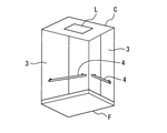
- FIG. 2 is a perspective view showing an elevator car according to the first embodiment.
- the basket 2 includes a floor F, a plurality of wall panels 3, a ceiling C, a lighting plate L, and a plurality of handrails 4.
- Floor F is provided at the bottom of the basket 2.
- the plurality of wall panels 3 are provided directly above the edge of the floor F.
- the ceiling C is provided directly above the upper edges of the plurality of wall panels 3.
- the lighting plate L is provided in the center of the ceiling C.
- the plurality of handrails 4 are provided on the plurality of wall panels 3, respectively.
- FIG. 3 is an exploded perspective view showing a main part of the handrail of the elevator car according to the first embodiment.
- the handrail 4 includes a gripping member 10, a reinforcing member 11, and a pair of caps 12.
- the grip member 10 has a rod shape.
- the grip member 10 has a round bar shape.
- the material of the gripping member 10 is wood.
- the gripping member 10 is arranged along the surface of the wall panel 3 with a gap between the grip member 10 and the surface of the wall panel 3.
- the grip member 10 is arranged with the longitudinal direction in the horizontal direction.
- the gripping member 10 includes a first notch 10a, a pair of second notches 10b, and a pair of first fixing holes 10c.
- the first notch 10a is recessed from the lower side to the center side of the outer peripheral surface of the gripping member 10.
- the first notch 10a is recessed from the lower side of the outer peripheral surface of the gripping member 10 to the upper side of the center.
- the first notch 10a extends from one end surface to the other end surface of the grip member 10 along the longitudinal direction of the grip member 10.
- One of the pair of second notches 10b is connected to the space outside the one end surface of the grip member 10 and the space outside the outer peripheral surface on the side of the wall panel 3 of the grip member 10.
- One of the pair of second notches 10b leads to the first notch 10a.
- one of the pair of second notches 10b is orthogonal to the first notch 10a.
- the other side of the pair of second notches 10b is connected to the space outside the other end surface of the grip member 10 and the space outside the outer peripheral surface on the side of the wall panel 3 of the grip member 10.
- the other of the pair of second notches 10b leads to the first notch 10a.
- the other of the pair of second notches 10b is orthogonal to the first notch 10a.
- the pair of first fixing holes 10c is provided on the side of the wall panel 3 in the gripping member 10.
- One of the pair of first fixing holes 10c is provided on one side of the gripping member 10 in the longitudinal direction more than one of the pair of second notches 10b on the side of the center of the gripping member 10 in the longitudinal direction.
- the other of the pair of first fixing holes 10c is provided on the other side of the grip member 10 in the longitudinal direction with respect to the other of the pair of second notches 10b on the side of the center of the grip member 10 in the longitudinal direction.
- Each of the pair of first fixing holes 10c is connected to the outer space of the gripping member 10 on the side of the wall panel 3 and the first notch 10a.
- the bottom of each of the pair of first fixing holes 10c is formed on the grip member 10 on the opposite side of the wall panel 3 with respect to the first notch 10a.
- the material of the reinforcing member 11 is a material having higher rigidity than the material of the gripping member 10.
- the material of the reinforcing member 11 is a steel material, a casting, a solid resin, or the like.
- the reinforcing member 11 has a rod shape.
- the reinforcing member 11 has a square bar shape.
- the length of the reinforcing member 11 in the longitudinal direction is substantially the same as the length of the grip member 10 in the longitudinal direction.
- the reinforcing member 11 includes a pair of second fixing holes 11a.
- Each of the pair of second fixing holes 11a is a screw hole.
- One of the pair of second fixing holes 11a is provided on one side of the reinforcing member 11 in the longitudinal direction.
- the other side of the pair of second fixing holes 11a is provided on the other side of the reinforcing member 11 in the longitudinal direction.
- the pair of second fixing holes 11a penetrate the reinforcing member 11 from the side of the wall panel 3 to the opposite side of the wall panel 3 with respect to the reinforcing member 11.
- the material of the pair of caps 12 is wood, solid resin, casting, or the like.
- One of the pair of caps 12 is provided on the side of one end of the gripping member 10 in the longitudinal direction.
- the other end of the pair of caps 12 is provided on the side of the other end of the gripping member 10 in the longitudinal direction.
- Each of the pair of caps 12 includes a lid portion 12a and a protrusion portion 12b.
- the lid portion 12a has an outer shape that matches the outer shape of the grip member 10 when viewed from the longitudinal direction of the grip member 10.
- the lid portion 12a has a disk shape.
- the protrusion 12b projects from the side of the wall panel 3 in the lid 12a toward the grip member 10.
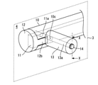
- FIG. 4 is a perspective view showing a main part of the handrail of the elevator car according to the first embodiment.
- the protrusion 12b is fitted into the second notch 10b.
- the surface on the side of the wall panel 3 is arranged so as to be continuously connected to the outer peripheral surface of the gripping member 10.
- the cap 12 is adhered to the gripping member 10.
- the lid portion 12a is adhered to the end surface of the gripping member 10.
- the protrusion 12b is adhered to the surface forming the second notch 10b of the gripping member 10.
- FIG. 5 is a side view showing a main part of the handrail of the elevator car according to the first embodiment.
- FIG. 5A shows a state in which the cap 12 is attached to the gripping member 10.
- FIG. 5B shows a state in which the adhesive between the gripping member 10 and the cap 12 is peeled off.
- the protrusion 12b is the surface of the gripping member 10 above and below the second notch 10b. It is maintained in a state of being sandwiched between. For example, when the adhesive is peeled off due to aging, the cap 12 is released from being fixed to the gripping member 10 by the adhesive.
- the cap 12 tends to rotate with the upper portion of the lid portion 12a as an axis in the direction in which the lower portion of the lid portion 12a is separated from the gripping member 10, the lower surface of the protrusion portion 12b is gripped below the second notch 10b. Rotation is suppressed by the surface of the member 10. As a result, the cap 12 does not fall off from the gripping member 10.
- FIG. 6 is a perspective view showing the handrail of the elevator car according to the first embodiment.
- the reinforcing member 11 is incorporated in the grip member 10 along the longitudinal direction of the grip member 10. Specifically, the reinforcing member 11 is fitted into the first notch 10a from below. At this time, the second fixing hole 11a is connected to the first fixing hole 10c. In this state, the reinforcing member 11 is adhered to the gripping member 10.
- the handrail 4 includes a pair of brackets 13.
- the pair of brackets 13 are aligned along the surface of the wall panel 3 between the wall panel 3 and the gripping member 10. In FIG. 6, only one of the pair of brackets 13 is shown. One of the pair of brackets 13 is provided on the side of one end of the gripping member 10. Although not shown, the other end of the pair of brackets 13 is provided on the side of the other end of the grip member 10.
- the material of the bracket 13 is wood, steel, casting, or the like.
- the material of the bracket 13 is wood.
- the bracket 13 has a rod shape.
- the bracket 13 has a round bar shape.
- One end surface of the bracket 13 has a shape that matches the outer peripheral surface of the gripping member 10 on the side of the wall panel 3. The other end surface of the bracket 13 is flat.
- the bracket 13 is provided with a third fixing hole 13a.
- the third fixing hole 13a penetrates the bracket 13 over one end surface and the other end surface of the bracket 13.
- the bracket 13 is provided between the grip member 10 and the surface of the wall panel 3. One end surface of the bracket 13 is in contact with the outer peripheral surface of the gripping member 10 on the side of the wall panel 3. One end surface of the bracket 13 is in contact with the outer peripheral surface of the protrusion 12b on the side of the wall panel 3. The other end surface of the bracket 13 is in contact with the wall panel 3.
- the third fixing hole 13a is connected to the first fixing hole 10c and the second fixing hole 11a.
- the first fastening body 14 penetrates the hole of the wall panel 3, the third fixing hole 13a of the bracket 13, and the first fixing hole 10c of the gripping member 10 from the back surface side of the wall panel 3, and the second fixing of the reinforcing member 11.
- the handrail 4 is fixed to the wall panel 3 by being screwed into the hole 11a.
- the surface of the protrusion 12b on the wall panel 3 side faces the one end surface of the bracket 13.
- the other of the pair of brackets 13 has the same configuration.
- FIG. 7 is a cross-sectional view taken along the line XX of FIG.
- the reinforcing member 11 is located at the center of the outer shape of the grip member 10 in a cross section orthogonal to the longitudinal direction of the grip member 10.
- the reinforcing member 11 closes the first notch 10a.
- the lower surface of the reinforcing member 11 is arranged at a position continuously connected to the outer peripheral surface of the gripping member 10 so that the step generated between the reinforcing member 11 and the gripping member 10 becomes small.
- the reinforcing member 11 has a higher rigidity than the gripping member 10.
- the reinforcing member 11 is built in the grip member 10 along the longitudinal direction of the grip member 10.
- a pair of first fasteners 14 penetrating each of the wall panel 3 and the pair of brackets 13 is screwed from the back surface side of the wall panel 3. Therefore, it is possible to suppress the bending of the gripping member 10 when a load is applied to the intermediate portion of the gripping member 10 in the longitudinal direction.
- the distance between the brackets 13 can be widened and the number of brackets 13 can be reduced.
- the first fastening body 14 penetrates the hole of the wall panel 3, the third fixing hole 13a of the bracket 13, and the first fixing hole 10c of the gripping member 10 from the back surface side of the wall panel 3, and the reinforcing member 11 is the first.
- the handrail 4 is fixed to the wall panel 3 by being screwed into the fixing hole 11a. Therefore, the wall panel 3, the bracket 13, the gripping member 10, and the reinforcing member 11 can be assembled at the same time. As a result, the handrail 4 can be easily attached to the wall panel 3.
- the reinforcing member 11 is located at the center of the outer shape of the gripping member 10 in a cross section orthogonal to the longitudinal direction of the gripping member 10. In this case, when a load is applied to the outer peripheral surface of the gripping member 10, the load is likely to act on the reinforcing member 11. Therefore, the gripping member 10 can be reinforced more reliably by the reinforcing member 11.
- the gripping member 10 has a first notch 10a.
- the reinforcing member 11 is fitted into the first notch 10a of the gripping member. Therefore, the reinforcing member 11 can be easily attached to the gripping member 10.
- first notch 10a is recessed from the lower side to the center side of the outer peripheral surface of the gripping member 10.
- the reinforcing member 11 is fitted into the first notch 10a of the gripping member 10 from below. Therefore, it is possible to prevent the handrail 4 from the inside of the car 2 from becoming unattractive.
- the gripping member 10 receives the protrusion of the cap in the second notch 10b. Therefore, even if the adhesive between the gripping member 10 and the cap 12 is peeled off, the cap 12 can be suppressed from falling.
- the second notch 10b is connected to the space outside the end surface of the gripping member 10 and the space outside the outer peripheral surface. Therefore, the second notch 10b can be easily machined by cutting. In particular, when the material of the gripping member 10 is a solid wood having excellent design, the second notch 10b can be easily processed.
- the second notch 10b is provided on the side of the wall panel 3 of the gripping member 10. Therefore, it is possible to prevent the handrail 4 from the inside of the car 2 from becoming unattractive.
- the surface of the protrusion 12b on the side of the wall panel 3 is continuously connected to the outer peripheral surface of the gripping member 10. Therefore, it is possible to reduce the step generated between the cap 12 and the gripping member 10 around the second notch 10b. As a result, the gripping member 10 can be easily gripped.
- the bracket 13 faces the side of the wall panel 3 in the protrusion 12b of the cap 12. Therefore, even if the adhesive between the gripping member 10 and the cap 12 is peeled off, it is possible to prevent the protrusion 12b of the cap 12 from moving toward the wall panel 3 with respect to the bracket 13. As a result, it is possible to prevent the cap 12 from falling off toward the wall panel 3.
- bracket 13 comes into contact with the side of the wall panel 3 in the protrusion 12b of the cap 12.
- bracket 13 does not come into contact with the side of the wall panel 3 in the protrusion 12b of the cap 12, it is desirable to minimize the gap between the bracket 13 and the side of the wall panel 3 in the protrusion 12b of the cap 12.
- the first notch 10a of the gripping member 10 extends from one end surface to the other end surface in the longitudinal direction of the gripping member 10. Therefore, when the first notch 10a is formed by cutting, it is not necessary to machine the end portion of the first notch 10a. As a result, the first notch 10a can be easily machined by cutting. Further, the first notch 10a can be cut from the outer peripheral surface of the gripping member 10. Therefore, the first notch 10a can be easily machined by cutting. In particular, even when the material of the gripping member 10 is a solid wood having excellent design, the first notch 10a can be easily processed.
- the reinforcing member 11 closes the first notch 10a. Specifically, the lower surface of the reinforcing member 11 is continuously connected to the outer peripheral surface of the gripping member 10. Therefore, it is possible to reduce the step generated between the reinforcing member 11 and the gripping member 10 around the first notch 10a. As a result, the gripping member 10 can be easily gripped. Further, when the gripping member 10 is pushed from below, the reinforcing member 11 is also pushed in the same manner as the gripping member 10. As a result, it is possible to prevent the gripping member 10 from coming off the reinforcing member 11.
- the length of the reinforcing member 11 in the longitudinal direction may be slightly shorter than the length of the gripping member 10 in the longitudinal direction.
- brackets 13 may be used.
- C chamfering or R chamfering may be performed on the edge portion on the opposite side of the gripping member 10.
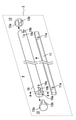
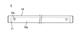
- FIG. 8 is a side view showing a modified example of the handrail of the elevator car according to the first embodiment.
- the first notch 10a is provided inside the gripping member 10 in the longitudinal direction with respect to one end surface and the other end surface of the gripping member 10.
- the first notch 10a does not connect to one end surface and the other end surface of the gripping member 10.
- the first notch 10a does not connect to one end surface and the other end surface of the gripping member 10.
- the cap 12 becomes unnecessary. Therefore, the number of parts of the handrail 4 can be reduced. As a result, the handrail 4 can be easily assembled.
- the end of the gripping member 10 may be chamfered. In this case, it is possible to provide the handrail 4 having excellent design and workability.
- FIG. 9 is an exploded perspective view showing a main part of the handrail of the elevator car according to the second embodiment.
- the same or corresponding parts as those of the first embodiment are designated by the same reference numerals. The explanation of this part is omitted.
- the second notch 10b of the second embodiment is longer in the longitudinal direction of the gripping member 10 than the second notch 10b of the first embodiment.
- the protrusion 12b of the second embodiment is longer in the longitudinal direction of the gripping member 10 than the protrusion 12b of the first embodiment.
- the fourth fixing hole 12c is provided in the protrusion 12b.
- the fourth fixing hole 12c penetrates the protrusion 12b from the side of the wall panel 3 to the opposite side of the wall panel 3 with respect to the protrusion 12b.
- FIG. 10 is a perspective view showing a main part of the handrail of the elevator car according to the second embodiment.
- the third fixing hole 13a is connected to the fourth fixing hole 12c and the second fixing hole 11a.
- the first fastening body 14 penetrates the hole of the wall panel 3, the third fixing hole 13a of the bracket 13, and the fourth fixing hole 12c of the cap 12 from the back surface side of the wall panel 3, and the second fixing of the reinforcing member 11 is performed.
- the handrail 4 is fixed to the wall panel 3 by being screwed into the hole 11a.
- the first fastening body 14 has a hole in the wall panel 3, a third fixing hole 13a in the bracket 13, and a fourth fixing hole 12c in the cap 12 from the back surface side of the wall panel 3. And screwed into the second fixing hole 11a of the reinforcing member 11. Therefore, the wall panel 3, the bracket 13, the cap 12, and the reinforcing member 11 can be assembled at the same time. As a result, the handrail 4 can be easily attached to the wall panel 3. Further, the cap 12 is restricted from moving to the first fastening body 14. Therefore, even if the adhesive is peeled off, it is possible to prevent the cap 12 from falling off from the gripping member 10.
- FIG. 11 is an exploded perspective view showing a main part of the handrail of the elevator car according to the third embodiment.
- the same or corresponding parts as those of the first embodiment are designated by the same reference numerals. The explanation of this part is omitted.
- the length of the reinforcing member 11 in the longitudinal direction is longer than the length of the gripping member 10 in the longitudinal direction.
- the reinforcing member 11 includes a pair of vertical holes 11b.
- One of the pair of vertical holes 11b is provided at one end of the reinforcing member 11.
- One of the pair of vertical holes 11b penetrates the reinforcing member 11 in the vertical direction.
- the other end of the pair of vertical holes 11b is provided at the other end of the reinforcing member 11.
- the other of the pair of vertical holes 11b penetrates the reinforcing member 11 in the vertical direction.
- Each of the pair of caps 12 includes a third notch 12d, a screw hole 12e, and a groove 12f.
- the third notch 12d is recessed from the lower side to the center side of the outer peripheral surface of the cap 12.
- the third notch 12d connects to the space on the side of the gripping member 10.
- the screw hole 12e is provided in the portion of the cap 12 above the third notch 12d from the lower side to the upper side.
- the groove 12f is provided on the outer peripheral surface of the cap 12 on the side of the gripping member 10.
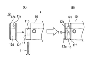
- FIG. 12 is a side view showing a main part of the handrail of the elevator car according to the third embodiment.
- the end portion of the reinforcing member 11 protrudes from the gripping member 10.
- the cap 12 is attached to the end of the reinforcing member 11 from the side.
- the third notch 12d is fitted to the end portion of the reinforcing member 11.
- the screw hole 12e is connected to the vertical hole 11b.
- the second fastening body 15 is screwed into the screw hole 12e of the cap 12 through the vertical hole 11b from below the end portion of the reinforcing member 11.
- the end portion of the reinforcing member 11 is fitted into the third notch 12d of the cap 12. Therefore, the cap 12 is supported from below by the end of the reinforcing member 11. Therefore, even if the adhesive is peeled off, it is possible to prevent the cap 12 from falling off from the end portion of the reinforcing member 11.
- the second fastening body 15 is screwed into the screw hole 12e of the cap 12 through the vertical hole 11b from below the end portion of the reinforcing member 11.
- the cap 12 is restrained from moving by the second fastener 15.
- the second fastening body 15 is restrained from moving by the vertical hole 11b of the reinforcing member 11. Therefore, the wobbling of the cap 12 is suppressed. As a result, it is possible to reliably prevent the cap 12 from falling off from the end portion of the reinforcing member 11 even without the adhesive.
- the second fastening body 15 is screwed in from below the end portion of the reinforcing member 11. Therefore, it is possible to prevent the handrail 4 from the inside of the car 2 from becoming unattractive.
- the handrail of the elevator car according to this disclosure can be used for the elevator car.
Landscapes
- Engineering & Computer Science (AREA)
- Civil Engineering (AREA)
- Mechanical Engineering (AREA)
- Structural Engineering (AREA)
- Cage And Drive Apparatuses For Elevators (AREA)
Abstract
把持部材に荷重がかかったときの把持部材の撓みを抑制することができるエレベーターのかごの手すりを提供する。エレベーターのかごの手すりは、エレベーターのかごの壁パネルの表面との間に隙間をあけて前記壁パネルの表面に沿って配置された把持部材と、前記壁パネルと前記把持部材との間において前記壁パネルの表面に沿って並んだ複数のブラケットと、前記把持部材よりも高い剛性を有し、前記把持部材の長手方向に沿って前記把持部材に内蔵され、前記壁パネルの裏面の側から前記壁パネルと前記複数のブラケットのそれぞれとを貫通した複数の第1締結体がねじ込まれた補強部材と、を備えた。
Description
本開示は、エレベーターのかごの手すりに関する。
特許文献1は、エレベーターのかごの手すりを開示する。当該手すりにおいて、締結体は、壁パネルとブラケットとを貫通して把持部材にねじ込まれる。
しかしながら、特許文献1に記載のエレベーターのかごの手すりにおいて、締結体は、把持部材に直接ねじ込まれる。この状態において、把持部材に大きな荷重がかかると、把持部材が大きく撓む。
本開示は、上述の課題を解決するためになされた。本開示の目的は、把持部材に荷重がかかったときの把持部材の撓みを抑制することができるエレベーターのかごの手すりを提供することである。
本開示に係るエレベーターのかごの手すりは、エレベーターのかごの壁パネルの表面との間に隙間をあけて前記壁パネルの表面に沿って配置された把持部材と、前記壁パネルと前記把持部材との間において前記壁パネルの表面に沿って並んだ複数のブラケットと、前記把持部材よりも高い剛性を有し、前記把持部材の長手方向に沿って前記把持部材に内蔵され、前記壁パネルの裏面の側から前記壁パネルと前記複数のブラケットのそれぞれとを貫通した複数の第1締結体がねじ込まれた補強部材と、を備えた。
本開示によれば、補強部材は、把持部材よりも高い剛性を有する。補強部材は、把持部材の長手方向に沿って把持部材に内蔵される。補強部材は、壁パネルの裏面の側から壁パネルと一対のブラケットのそれぞれとを貫通した一対の第1締結体がねじ込まれる。このため、把持部材に荷重がかかったときの把持部材の撓みを抑制することができる。
本開示を実施するための形態について添付の図面に従って説明する。なお、各図中、同一または相当する部分には同一の符号が付される。当該部分の重複説明は適宜に簡略化ないし省略される。
実施の形態1.
図1は実施の形態1におけるエレベーターの概要を示す斜視図である。
図1は実施の形態1におけるエレベーターの概要を示す斜視図である。
図1のエレベーターにおいて、昇降路1は、建築物の各階を貫く。かご2は、昇降路1に配置される。かごドアDは、かご2の出入口に設けられる。
図2は実施の形態1におけるエレベーターのかごを示す斜視図である。
図2に示されるように、かご2は、床Fと複数の壁パネル3と天井Cと照明板Lと複数の手すり4とを備える。
床Fは、かご2の下部に設けられる。複数の壁パネル3は、床Fの縁部の直上に設けられる。天井Cは、複数の壁パネル3の上縁部の直上に設けられる。照明板Lは、天井Cの中央に設けられる。複数の手すり4は、複数の壁パネル3にそれぞれ設けられる。
次に、図3を用いて、手すり4の要部を説明する。
図3は実施の形態1におけるエレベーターのかごの手すりの要部を示す分解斜視図である。
図3は実施の形態1におけるエレベーターのかごの手すりの要部を示す分解斜視図である。
図3に示されるように、手すり4は、把持部材10と補強部材11と一対のキャップ12とを備える。
把持部材10は、棒状である。例えば、把持部材10は、丸棒状である。例えば、把持部材10の材質は、木材である。把持部材10は、壁パネル3の表面との間に隙間を開けて壁パネル3の表面に沿って配置される。把持部材10は、長手方向を水平方向にして配置される。把持部材10は、第1切欠10aと一対の第2切欠10bと一対の第1固定穴10cとを備える。
例えば、第1切欠10aは、把持部材10の外周面の下側から中心の側へ凹む。例えば、第1切欠10aは、把持部材10の外周面の下側から中心よりも上側まで凹む。例えば、第1切欠10aは、把持部材10の長手方向に沿って把持部材10の一端面から他端面にわたる。
一対の第2切欠10bの一方は、把持部材10の壁パネル3の側において把持部材10の一端面の外側の空間と外周面の外側の空間とにつながる。一対の第2切欠10bの一方は、第1切欠10aにつながる。把持部材10の長手方向から見た場合、一対の第2切欠10bの一方は、第1切欠10aと直交する。
一対の第2切欠10bの他方は、把持部材10の壁パネル3の側において把持部材10の他端面の外側の空間と外周面の外側の空間とにつながる。一対の第2切欠10bの他方は、第1切欠10aにつながる。把持部材10の長手方向から見た場合、一対の第2切欠10bの他方は、第1切欠10aと直交する。
一対の第1固定穴10cは、把持部材10における壁パネル3の側に設けられる。一対の第1固定穴10cの一方は、把持部材10の長手方向の一側において一対の第2切欠10bの一方よりも把持部材10の長手方向の中心の側に設けられる。一対の第1固定穴10cの他方は、把持部材10の長手方向の他側において一対の第2切欠10bの他方よりも把持部材10の長手方向の中心の側に設けられる。一対の第1固定穴10cの各々は、把持部材10の壁パネル3の側における外側の空間と第1切欠10aとにつながる。例えば、一対の第1固定穴10cの各々の底部は、第1切欠10aに対して壁パネル3とは反対側において把持部材10に形成される。
補強部材11の材質は、把持部材10の材質よりも剛性の高い材質である。例えば、補強部材11の材質は、鋼材、鋳物、固体樹脂等である。補強部材11は、棒状である。例えば、補強部材11は、角棒状である。補強部材11の長手方向の長さは、把持部材10の長手方向の長さとほぼ同じ長さである。
補強部材11は、一対の第2固定穴11aを備える。一対の第2固定穴11aの各々は、ねじ穴である。一対の第2固定穴11aの一方は、補強部材11の長手方向の一側に設けられる。一対の第2固定穴11aの他方は、補強部材11の長手方向の他側に設けられる。例えば、一対の第2固定穴11aは、補強部材11に対して壁パネル3の側から壁パネル3の反対側まで補強部材11を貫通する。
例えば、一対のキャップ12の材質は、木材、固体樹脂、鋳物、等である。一対のキャップ12の一方は、把持部材10の長手方向の一端部の側に設けられる。一対のキャップ12の他方は、把持部材10の長手方向の他端部の側に設けられる。
一対のキャップ12の各々は、蓋部12aと突起部12bとを備える。
一対のキャップ12の各々において、蓋部12aは、把持部材10の長手方向から見た際の把持部材10の外形に合わせた外形を有する。例えば、蓋部12aは、円盤状である。突起部12bは、蓋部12aにおける壁パネル3の側から把持部材10の側に突き出す。
次に、図4を用いて、キャップ12の取付方法を説明する。
図4は実施の形態1におけるエレベーターのかごの手すりの要部を示す斜視図である。
図4は実施の形態1におけるエレベーターのかごの手すりの要部を示す斜視図である。
図4に示されるように、キャップ12において、突起部12bは、第2切欠10bに嵌め合わされる。突起部12bにおいて、壁パネル3の側の面は、把持部材10の外周面と連続的につながるように配置される。この状態において、キャップ12は、把持部材10に接着される。例えば、蓋部12aは、把持部材10の端面に接着される。例えば、突起部12bは、把持部材10の第2切欠10bを形成する面に接着される。
次に、図5を用いて、キャップ12の保持方法を説明する。
図5は実施の形態1におけるエレベーターのかごの手すりの要部を示す側面図である。図5の(A)は、キャップ12が把持部材10に取り付けられた状態を示す。図5の(B)は、把持部材10とキャップ12との間の接着剤が剥離した状態を示す。
図5は実施の形態1におけるエレベーターのかごの手すりの要部を示す側面図である。図5の(A)は、キャップ12が把持部材10に取り付けられた状態を示す。図5の(B)は、把持部材10とキャップ12との間の接着剤が剥離した状態を示す。
図5の(A)に示されるように、キャップ12が接着剤により強固に把持部材10に固定されている場合、突起部12bは、第2切欠10bの上方および下方にある把持部材10の面に挟み込まれた状態に維持される。例えば、接着剤が経年劣化により剥離すると、キャップ12は、接着剤による把持部材10への固定から解放される。
この状態において、図5の(B)の矢印に示されるように、キャップ12が外部からの力を受けると、キャップ12は、蓋部12aの下部を軸として蓋部12aの上部が把持部材10から離れる方向に回転しようとする。この際、突起部12bの上面は、第2切欠10bの上方にある把持部材10の面に回転を抑制される。その結果、キャップ12は、把持部材10から脱落しない。
図示されないが、キャップ12が蓋部12aの上部を軸として蓋部12aの下部が把持部材10から離れる方向に回転しようとする際、突起部12bの下面は、第2切欠10bの下方にある把持部材10の面に回転を抑制される。その結果、キャップ12は、把持部材10から脱落しない。
次に、図6を用いて、手すり4の取付方法を説明する。
図6は実施の形態1におけるエレベーターのかごの手すりを示す斜視図である。
図6は実施の形態1におけるエレベーターのかごの手すりを示す斜視図である。
図6に示されるように、補強部材11は、把持部材10の長手方向に沿って把持部材10に内蔵される。具体的には、補強部材11は、第1切欠10aに下方から嵌め合わされる。この際、第2固定穴11aは、第1固定穴10cにつながる。この状態において、補強部材11は、把持部材10に接着される。
手すり4は、一対のブラケット13を備える。一対のブラケット13は、壁パネル3と把持部材10との間において壁パネル3の表面に沿って並ぶ。図6においては、一対のブラケット13の一方のみが示される。一対のブラケット13の一方は、把持部材10の一端部の側に設けられる。図示されないが、一対のブラケット13の他方は、把持部材10の他端部の側に設けられる。
例えば、ブラケット13の材質は、木材、鋼材、鋳物、等である。実施の形態1において、ブラケット13の材質は、木材である。ブラケット13は、棒状である。実施の形態1において、ブラケット13は、丸棒状である。ブラケット13の一端面は、把持部材10における壁パネル3の側の外周面に合わせた形状である。ブラケット13の他端面は、平面状である。
ブラケット13は、第3固定穴13aを備える。第3固定穴13aは、ブラケット13の一端面と他端面とにわたってブラケット13を貫通する。
ブラケット13は、把持部材10と壁パネル3の表面との間に設けられる。ブラケット13の一端面は、把持部材10における壁パネル3の側の外周面に接する。ブラケット13の一端面は、突起部12bにおける壁パネル3の側の外周面に接する。ブラケット13の他端面は、壁パネル3に接する。第3固定穴13aは、第1固定穴10cと第2固定穴11aとにつながる。
第1締結体14は、壁パネル3の裏面の側から壁パネル3の穴とブラケット13の第3固定穴13aと把持部材10の第1固定穴10cを貫通して補強部材11の第2固定穴11aにねじ込まれることで、手すり4を壁パネル3に固定する。
この際、キャップ12において、突起部12bの壁パネル3の側の面は、ブラケット13の一端面と対向する。
図示されないが、一対のブラケット13の他方も、同様の構成である。
次に、図7を用いて、把持部材10と補強部材11との位置関係を説明する。
図7は図6のX-X線における断面図である。
図7は図6のX-X線における断面図である。
図7に示されるように、補強部材11は、把持部材10の長手方向と直交する断面において把持部材10の外形の中心に位置する。補強部材11は、第1切欠10aを塞ぐ。具体的には、補強部材11と把持部材10との間に生じる段差が小さくなるように、補強部材11の下面は、把持部材10の外周面と連続的につながる位置に配置される。
以上で説明した実施の形態1によれば、補強部材11は、把持部材10よりも高い剛性を有する。補強部材11は、把持部材10の長手方向に沿って把持部材10に内蔵される。補強部材11は、壁パネル3の裏面の側から壁パネル3と一対のブラケット13のそれぞれとを貫通した一対の第1締結体14がねじ込まれる。このため、把持部材10の長手方向の中間部に荷重がかかったときの把持部材10の撓みを抑制することができる。その結果、ブラケット13の間隔を広げたり、ブラケット13の数を減らしたりすることができる。
また、第1締結体14は、壁パネル3の裏面の側から壁パネル3の穴とブラケット13の第3固定穴13aと把持部材10の第1固定穴10cを貫通して補強部材11の第2固定穴11aにねじ込まれることで、手すり4を壁パネル3に固定する。このため、壁パネル3とブラケット13と把持部材10と補強部材11とを同時に組み付けることができる。その結果、手すり4を壁パネル3に容易に取り付けることができる。
また、補強部材11は、把持部材10の長手方向と直交する断面において把持部材10の外形の中心に位置する。この場合、把持部材10の外周面に荷重がかかった際、当該荷重が補強部材11に作用しやすくなる。このため、補強部材11により把持部材10をより確実に補強することができる。
また、把持部材10は、第1切欠10aを有する。補強部材11は、把持部材の第1切欠10aに嵌め合わされる。このため、補強部材11を把持部材10に容易に装着することができる。
また、第1切欠10aは、把持部材10の外周面の下側から中心の側へ凹む。補強部材11は、把持部材10の第1切欠10aに下方から嵌め合わされる。このため、かご2の内部からの手すり4の見栄えが悪くなることを抑制できる。
また、把持部材10は、第2切欠10bにおいてキャップの突起部を受け入れる。このため、把持部材10とキャップ12との間の接着剤が剥離した場合でも、キャップ12の落下を抑制することができる。
また、第2切欠10bは、把持部材10の端面の外側の空間と外周面の外側の空間とにつながる。このため、第2切欠10bを切削により容易に加工することができる。特に、把持部材10の材料が意匠性に優れた無垢材である場合、第2切欠10bを容易に加工することができる。
また、第2切欠10bは、把持部材10の壁パネル3の側に設けられる。このため、かご2の内部からの手すり4の見栄えが悪くなることを抑制できる。
また、キャップ12において、突起部12bにおける壁パネル3の側の面は、把持部材10の外周面と連続的につながる。このため、第2切欠10bの周辺において、キャップ12と把持部材10との間に生じる段差を小さくすることができる。その結果、把持部材10を握られやすくすることができる。
なお、第2切欠10bの周辺において、キャップ12と把持部材10との間に生じる段差と隙間とを極力小さくすることが望ましい。
また、ブラケット13は、キャップ12の突起部12bにおける壁パネル3の側に対向する。このため、把持部材10とキャップ12との間の接着剤が剥離した場合でも、キャップ12の突起部12bがブラケット13よりも壁パネル3の側へ移動することを抑制できる。その結果、キャップ12が壁パネル3の側へ脱落することを抑制できる。
なお、ブラケット13は、キャップ12の突起部12bにおける壁パネル3の側と接触することが望ましい。ブラケット13がキャップ12の突起部12bにおける壁パネル3の側と接触しない場合、ブラケット13とキャップ12の突起部12bにおける壁パネル3の側との間の隙間を極力小さくすることが望ましい。
また、把持部材10の第1切欠10aは、把持部材10の長手方向の一端面から他端面にわたる。このため、第1切欠10aが切削加工によって形成される場合、第1切欠10aの端部の加工が不要となる。その結果、第1切欠10aを切削により容易に加工することができる。また、把持部材10の外周面から第1切欠10aを切削することができる。このため、第1切欠10aを切削により容易に加工することができる。特に、把持部材10の材料が意匠性に優れた無垢材である場合でも、第1切欠10aを容易に加工することができる。
また、補強部材11は、第1切欠10aを塞ぐ。具体的には、補強部材11の下面は、把持部材10の外周面と連続的につながる。このため、第1切欠10aの周辺において、補強部材11と把持部材10との間に生じる段差を小さくすることができる。その結果、把持部材10を握られやすくすることができる。さらに、把持部材10が下方から押された場合、補強部材11も把持部材10と同様に押される。その結果、把持部材10が補強部材11から外れることを抑制できる。
なお、第1切欠10aの周辺において、補強部材11と把持部材10との間に生じる段差と隙間とを極力小さくすることが望ましい。
また、補強部材11の長手方向の長さを、把持部材10の長手方向の長さよりも若干短くしてもよい。
また、3つ以上のブラケット13を用いてよい。
また、キャップ12において、把持部材10とは反対側の縁部にC面取りまたはR面取りを施してもよい。
次に、図8を用いて、手すり4の変形例を説明する。
図8は実施の形態1におけるエレベーターのかごの手すりの変形例を示す側面図である。
図8は実施の形態1におけるエレベーターのかごの手すりの変形例を示す側面図である。
当該変形例において、第1切欠10aは、把持部材10の一端面および他端面よりも把持部材10の長手方向の内側に設けられる。第1切欠10aは、把持部材10の一端面と他端面とにつながらない。
以上で説明した実施の形態1の変形例によれば、第1切欠10aは、把持部材10の一端面と他端面とにつながらない。この場合、キャップ12が不要となる。このため、手すり4の部品点数を削減することができる。その結果、手すり4を容易に組み立てることができる。
なお、把持部材10の端部に面取りを施してもよい。この場合、意匠性および工作性に優れた手すり4を提供することができる。
実施の形態2.
図9は実施の形態2におけるエレベーターのかごの手すりの要部を示す分解斜視図である。なお、実施の形態1の部分と同一又は相当部分には同一符号が付される。当該部分の説明は省略される。
図9は実施の形態2におけるエレベーターのかごの手すりの要部を示す分解斜視図である。なお、実施の形態1の部分と同一又は相当部分には同一符号が付される。当該部分の説明は省略される。
図9において、実施の形態2の第2切欠10bは、実施の形態1における第2切欠10bよりも把持部材10の長手方向に長い。実施の形態2の突起部12bは、実施の形態1における突起部12bよりも把持部材10の長手方向に長い。
第4固定穴12cは、突起部12bに設けられる。第4固定穴12cは、突起部12bに対して壁パネル3の側から壁パネル3の反対側まで突起部12bを貫通する。
次に、図10を用いて、手すり4の取付方法を説明する。
図10は実施の形態2におけるエレベーターのかごの手すりの要部を示す斜視図である。
図10は実施の形態2におけるエレベーターのかごの手すりの要部を示す斜視図である。
図10に示されるように、第3固定穴13aは、第4固定穴12cと第2固定穴11aとに繋がる。
第1締結体14は、壁パネル3の裏面の側から壁パネル3の穴とブラケット13の第3固定穴13aとキャップ12の第4固定穴12cとを貫通して補強部材11の第2固定穴11aにねじ込まれることで、手すり4を壁パネル3に固定する。
以上で説明した実施の形態2によれば、第1締結体14は、壁パネル3の裏面の側から壁パネル3の穴とブラケット13の第3固定穴13aとキャップ12の第4固定穴12cとを貫通して補強部材11の第2固定穴11aにねじ込まれる。このため、壁パネル3とブラケット13とキャップ12と補強部材11とを同時に組み付けることができる。その結果、手すり4を壁パネル3に容易に取り付けることができる。また、キャップ12は、第1締結体14に移動を制限される。このため、接着剤が剥離した場合でも、キャップ12が把持部材10から脱落することを抑制できる。
実施の形態3.
図11は実施の形態3におけるエレベーターのかごの手すりの要部を示す分解斜視図である。なお、実施の形態1の部分と同一又は相当部分には同一符号が付される。当該部分の説明は省略される。
図11は実施の形態3におけるエレベーターのかごの手すりの要部を示す分解斜視図である。なお、実施の形態1の部分と同一又は相当部分には同一符号が付される。当該部分の説明は省略される。
図11に示されるように、実施の形態3において、補強部材11の長手方向の長さは、把持部材10の長手方向の長さより長い。補強部材11は、一対の縦穴11bを備える。
一対の縦穴11bの一方は、補強部材11の一端部に設けられる。一対の縦穴11bの一方は、補強部材11を上下方向に貫通する。一対の縦穴11bの他方は、補強部材11の他端部に設けられる。一対の縦穴11bの他方は、補強部材11を上下方向に貫通する。
一対のキャップ12の各々は、第3切欠12dとネジ穴12eと溝12fとを備える。
第3切欠12dは、キャップ12の外周面の下側から中心の側へ凹む。第3切欠12dは、把持部材10の側の空間につながる。
ネジ穴12eは、第3切欠12dの上方にあるキャップ12の部分に下側から上方向に設けられる。
溝12fは、キャップ12の外周面における把持部材10の側に設けられる。
次に、図12を用いて、手すり4の要部の組立方法を説明する。
図12は実施の形態3におけるエレベーターのかごの手すりの要部を示す側面図である。
図12は実施の形態3におけるエレベーターのかごの手すりの要部を示す側面図である。
図12の(A)に示されるように、補強部材11の端部は、把持部材10から突き出る。キャップ12は、側方から補強部材11の端部に取り付けられる。
この際、図12の(B)に示されるように、キャップ12において、第3切欠12dは、補強部材11の端部に嵌め合わされる。この状態において、ネジ穴12eは、縦穴11bにつながる。第2締結体15は、補強部材11の端部の下方から縦穴11bを貫通してキャップ12のネジ穴12eにねじ込まれる。
以上で説明した実施の形態3によれば、補強部材11の端部は、キャップ12の第3切欠12dに嵌め合わされる。このため、キャップ12は、補強部材11の端部に下方から支持される。このため、接着剤が剥離した場合でも、キャップ12が補強部材11の端部から脱落することを抑制できる。
また、第2締結体15は、補強部材11の端部の下方から縦穴11bを貫通してキャップ12のネジ穴12eにねじ込まれる。この場合、キャップ12は、第2締結体15に移動を拘束される。第2締結体15は、補強部材11の縦穴11bに移動を拘束される。このため、キャップ12のぐらつきが抑制される。その結果、接着剤がなくても、キャップ12が補強部材11の端部から脱落することを確実に抑制できる。
また、第2締結体15は、補強部材11の端部の下方からねじ込まれる。このため、かご2の内部からの手すり4の見栄えが悪くなることを抑制できる。
以上のように、本開示に係るエレベーターのかごの手すりは、エレベーターのかごに利用できる。
1 昇降路、 2 かご、 3 壁パネル、 4 手すり、 10 把持部材、 10a 第1切欠、 10b 第2切欠、 10c 第1固定穴、 11 補強部材、 11a 第2固定穴、 11b 縦穴、 12 キャップ、 12a 蓋部、 12b 突起部、 12c 第4固定穴、 12d 第3切欠、 12e ネジ穴、 12f 溝、 13 ブラケット、 13a 第3固定穴、 14 第1締結体、 15 第2締結体
Claims (12)
- エレベーターのかごの壁パネルの表面との間に隙間をあけて前記壁パネルの表面に沿って配置された把持部材と、
前記壁パネルと前記把持部材との間において前記壁パネルの表面に沿って並んだ複数のブラケットと、
前記把持部材よりも高い剛性を有し、前記把持部材の長手方向に沿って前記把持部材に内蔵され、前記壁パネルの裏面の側から前記壁パネルと前記複数のブラケットのそれぞれとを貫通した複数の第1締結体がねじ込まれた補強部材と、
を備えたエレベーターのかごの手すり。 - 前記補強部材は、前記把持部材の長手方向と直交する断面において前記把持部材の外形の中心に位置した請求項1に記載のエレベーターのかごの手すり。
- 前記把持部材は、外周面の側から中心の側へ凹んだ第1切欠を有し、
前記補強部材は、前記把持部材の前記第1切欠に嵌め合わされた請求項1または請求項2に記載のエレベーターのかごの手すり。 - 前記把持部材は、前記第1切欠が外周面の下側から中心の側へ凹んだ請求項3に記載のエレベーターのかごの手すり。
- 前記把持部材の長手方向から見た際の前記把持部材の外形に合わせた外形を有した蓋部と、
前記蓋部における前記壁パネルの側から前記把持部材の側に突き出した突起部と、
を有したキャップ、
を備え、
前記把持部材は、前記壁パネルの側において端面の外側の空間と外周面の外側の空間とにつながる第2切欠を有し、前記第2切欠において前記キャップの前記突起部を受け入れた請求項4に記載のエレベーターのかごの手すり。 - 前記キャップは、前記突起部における前記壁パネルの側の面が前記把持部材の外周面と連続的につながった請求項5に記載のエレベーターのかごの手すり。
- 前記複数のブラケットのうちの一つは、前記キャップの前記突起部における前記壁パネルの側に対向した請求項5または請求項6に記載のエレベーターのかごの手すり。
- 前記キャップは、前記突起部が前記第1締結体に貫通された請求項7に記載のエレベーターのかごの手すり。
- 前記把持部材の長手方向から見た際の前記把持部材の外形に合わせた外形を有し、外周面の下側から中心の側へ凹んで前記把持部材の側の空間につながった第3切欠を有したキャップ、
を備え、
前記把持部材は、前記第1切欠が前記把持部材の長手方向の一端面と他端とにつながり、
前記補強部材は、前記把持部材の前記第1切欠と前記第3切欠に嵌め合わされた請求項4に記載のエレベーターのかごの手すり。 - 前記キャップは、前記補強部材の端部を下方から貫通した第2締結体がねじ込まれた請求項9に記載のエレベーターのかごの手すり。
- 前記把持部材は、前記第1切欠が長手方向の一端面と他端面とにつながらない請求項4に記載のエレベーターのかごの手すり。
- 前記補強部材は、下面が前記把持部材の外周面と連続的につながった請求項4から請求項11のいずれか一項に記載のエレベーターのかごの手すり。
Priority Applications (3)
| Application Number | Priority Date | Filing Date | Title |
|---|---|---|---|
| CN202080099847.3A CN115836023A (zh) | 2020-07-22 | 2020-07-22 | 电梯的轿厢的扶手 |
| JP2021504319A JP6863544B1 (ja) | 2020-07-22 | 2020-07-22 | エレベーターのかごの手すり |
| PCT/JP2020/028558 WO2022018871A1 (ja) | 2020-07-22 | 2020-07-22 | エレベーターのかごの手すり |
Applications Claiming Priority (1)
| Application Number | Priority Date | Filing Date | Title |
|---|---|---|---|
| PCT/JP2020/028558 WO2022018871A1 (ja) | 2020-07-22 | 2020-07-22 | エレベーターのかごの手すり |
Publications (1)
| Publication Number | Publication Date |
|---|---|
| WO2022018871A1 true WO2022018871A1 (ja) | 2022-01-27 |
Family
ID=75520953
Family Applications (1)
| Application Number | Title | Priority Date | Filing Date |
|---|---|---|---|
| PCT/JP2020/028558 Ceased WO2022018871A1 (ja) | 2020-07-22 | 2020-07-22 | エレベーターのかごの手すり |
Country Status (3)
| Country | Link |
|---|---|
| JP (1) | JP6863544B1 (ja) |
| CN (1) | CN115836023A (ja) |
| WO (1) | WO2022018871A1 (ja) |
Citations (6)
| Publication number | Priority date | Publication date | Assignee | Title |
|---|---|---|---|---|
| JPS6019575U (ja) * | 1983-07-18 | 1985-02-09 | 三菱電機株式会社 | エレベ−タかご室の手摺装置 |
| JPH0663720U (ja) * | 1993-02-16 | 1994-09-09 | ナカ工業株式会社 | 手摺のエンドキャップ |
| JPH08120875A (ja) * | 1994-08-30 | 1996-05-14 | Natl House Ind Co Ltd | 階段手摺り装置 |
| JPH1068207A (ja) * | 1996-08-28 | 1998-03-10 | Kenyuu:Kk | 合成樹脂製手摺の取付構造及びこれに用いるブラケット取付板並びにこれらを利用した手摺の取付方法。 |
| JP2004011383A (ja) * | 2002-06-11 | 2004-01-15 | Matsushita Electric Works Ltd | 手摺りの取付け構造 |
| JP2007512210A (ja) * | 2005-01-13 | 2007-05-17 | シク ヨーン,イ | 長さ調整が可能なエレベータの乗客用取っ手 |
Family Cites Families (5)
| Publication number | Priority date | Publication date | Assignee | Title |
|---|---|---|---|---|
| JPH08120876A (ja) * | 1994-08-30 | 1996-05-14 | Natl House Ind Co Ltd | 階段手摺り装置 |
| JP3842773B2 (ja) * | 2003-09-18 | 2006-11-08 | タカラ産業株式会社 | 手摺並びに面格子等に於ける構成部材のエンドキャップ |
| JP3865073B2 (ja) * | 2004-09-09 | 2007-01-10 | 株式会社ベスト | 手摺り |
| KR200460692Y1 (ko) * | 2010-11-29 | 2012-06-08 | 현대엘리베이터주식회사 | 엘이디 조명 일체형 장애인용 엘리베이터의 수평 손잡이 |
| JP2012218838A (ja) * | 2011-04-05 | 2012-11-12 | Toshiba Elevator Co Ltd | エレベータ乗りかご手摺装置 |
-
2020
- 2020-07-22 JP JP2021504319A patent/JP6863544B1/ja not_active Expired - Fee Related
- 2020-07-22 CN CN202080099847.3A patent/CN115836023A/zh active Pending
- 2020-07-22 WO PCT/JP2020/028558 patent/WO2022018871A1/ja not_active Ceased
Patent Citations (6)
| Publication number | Priority date | Publication date | Assignee | Title |
|---|---|---|---|---|
| JPS6019575U (ja) * | 1983-07-18 | 1985-02-09 | 三菱電機株式会社 | エレベ−タかご室の手摺装置 |
| JPH0663720U (ja) * | 1993-02-16 | 1994-09-09 | ナカ工業株式会社 | 手摺のエンドキャップ |
| JPH08120875A (ja) * | 1994-08-30 | 1996-05-14 | Natl House Ind Co Ltd | 階段手摺り装置 |
| JPH1068207A (ja) * | 1996-08-28 | 1998-03-10 | Kenyuu:Kk | 合成樹脂製手摺の取付構造及びこれに用いるブラケット取付板並びにこれらを利用した手摺の取付方法。 |
| JP2004011383A (ja) * | 2002-06-11 | 2004-01-15 | Matsushita Electric Works Ltd | 手摺りの取付け構造 |
| JP2007512210A (ja) * | 2005-01-13 | 2007-05-17 | シク ヨーン,イ | 長さ調整が可能なエレベータの乗客用取っ手 |
Also Published As
| Publication number | Publication date |
|---|---|
| CN115836023A (zh) | 2023-03-21 |
| JPWO2022018871A1 (ja) | 2022-01-27 |
| JP6863544B1 (ja) | 2021-04-21 |
Similar Documents
| Publication | Publication Date | Title |
|---|---|---|
| US4430835A (en) | Elevator cab | |
| JP6863544B1 (ja) | エレベーターのかごの手すり | |
| KR102086247B1 (ko) | 엘리베이터 케이지 | |
| JP2016169565A (ja) | 面内せん断耐力構造、及びその面内せん断耐力構造を備えた屋根構造、壁構造、床構造 | |
| JP6242176B2 (ja) | エレベータのかご床およびその製造方法 | |
| JP6982436B2 (ja) | デッキプレート用固定金具 | |
| JP7136279B1 (ja) | エレベータのかご室壁 | |
| JP7343058B2 (ja) | 乗客コンベアの欄干 | |
| JP7149835B2 (ja) | 乗りかご及びエレベーター | |
| KR20190040413A (ko) | 모서리가 절곡된 방음, 방진용 패널 및 그의 제작방법 | |
| JP2005042494A (ja) | 補強梁 | |
| JP2005320748A (ja) | 建物の耐力壁パネル | |
| KR200362207Y1 (ko) | 엘리베이터의 핸드레일 | |
| KR101684193B1 (ko) | 차량의 어셈블리 | |
| JP6719944B2 (ja) | 支柱受け床下地構造および支持部材 | |
| JP7720716B2 (ja) | エレベーターのパネル補強装置及び補強装置付きパネル | |
| JP4880844B2 (ja) | エレベータの三方枠 | |
| JP2020117873A (ja) | 耐力壁、耐力壁用の面材及び建物 | |
| WO2017203619A1 (ja) | エレベータのかご室壁 | |
| WO2023021653A1 (ja) | 乗りかご及びエレベーター | |
| JP2011074643A (ja) | 複合ドア | |
| JP6802086B2 (ja) | 耐力壁およびその施工方法 | |
| KR200242638Y1 (ko) | 창호고정용 분리형 클립 | |
| JPH01156292A (ja) | エレベーターかごの床 | |
| WO2021130994A1 (ja) | 長尺物の固定具および固定装置 |
Legal Events
| Date | Code | Title | Description |
|---|---|---|---|
| ENP | Entry into the national phase |
Ref document number: 2021504319 Country of ref document: JP Kind code of ref document: A |
|
| 121 | Ep: the epo has been informed by wipo that ep was designated in this application |
Ref document number: 20945860 Country of ref document: EP Kind code of ref document: A1 |
|
| NENP | Non-entry into the national phase |
Ref country code: DE |
|
| 122 | Ep: pct application non-entry in european phase |
Ref document number: 20945860 Country of ref document: EP Kind code of ref document: A1 |