WO2022014621A1 - バネ部材及びスイッチ - Google Patents
バネ部材及びスイッチ Download PDFInfo
- Publication number
- WO2022014621A1 WO2022014621A1 PCT/JP2021/026370 JP2021026370W WO2022014621A1 WO 2022014621 A1 WO2022014621 A1 WO 2022014621A1 JP 2021026370 W JP2021026370 W JP 2021026370W WO 2022014621 A1 WO2022014621 A1 WO 2022014621A1
- Authority
- WO
- WIPO (PCT)
- Prior art keywords
- spring member
- dome
- bent
- bent portion
- row region
- Prior art date
- Legal status (The legal status is an assumption and is not a legal conclusion. Google has not performed a legal analysis and makes no representation as to the accuracy of the status listed.)
- Ceased
Links
Images







Classifications
-
- H—ELECTRICITY
- H01—ELECTRIC ELEMENTS
- H01H—ELECTRIC SWITCHES; RELAYS; SELECTORS; EMERGENCY PROTECTIVE DEVICES
- H01H13/00—Switches having rectilinearly-movable operating part or parts adapted for pushing or pulling in one direction only, e.g. push-button switch
- H01H13/02—Details
- H01H13/26—Snap-action arrangements depending upon deformation of elastic members
- H01H13/48—Snap-action arrangements depending upon deformation of elastic members using buckling of disc springs
-
- H—ELECTRICITY
- H01—ELECTRIC ELEMENTS
- H01H—ELECTRIC SWITCHES; RELAYS; SELECTORS; EMERGENCY PROTECTIVE DEVICES
- H01H13/00—Switches having rectilinearly-movable operating part or parts adapted for pushing or pulling in one direction only, e.g. push-button switch
- H01H13/50—Switches having rectilinearly-movable operating part or parts adapted for pushing or pulling in one direction only, e.g. push-button switch having a single operating member
- H01H13/52—Switches having rectilinearly-movable operating part or parts adapted for pushing or pulling in one direction only, e.g. push-button switch having a single operating member the contact returning to its original state immediately upon removal of operating force, e.g. bell-push switch
Definitions
- This disclosure relates to spring members and switches.
- a push-type switch is known that uses a spring member that reverses when the dome portion is pressed as a movable contact.
- the spring member used as the movable contact of the push type switch is also called a tact spring.
- the dome portion of the spring member is pressed and inverted to come into contact with the fixed contact arranged on the substrate, so that the switch is turned on. Further, when the dome portion of the spring member is not pressed and is separated from the fixed contact arranged on the substrate, the switch is turned off.
- the spring member is formed by punching out the coil material, but when the coil material is punched out to form the spring member, a fracture surface is formed on the outer peripheral green portion of the spring member. Each time the spring member of the switch reverses due to pressing, stress is applied to the outer peripheral green portion where the fracture surface is formed, so that the spring member cracks from the outer peripheral green portion where the fracture surface is formed toward the inside of the spring member. May be formed.
- Japanese Patent Application Laid-Open No. 2016-181365 describes a spring member in which a protruding portion is extended at two locations along the longitudinal direction of the dome portion with the central portion of the dome portion interposed therebetween. Since the spring member described in JP-A-2016-181365 has protruding portions extending in two places along the longitudinal direction of the dome portion with the central portion of the dome portion sandwiched therein, the inside at the outer peripheral end portion. It is possible to reduce the concentration of stress, reduce the occurrence of cracks at the outer peripheral end, and extend the service life.
- the spring member according to the book has a dome-shaped dome portion that is convex upward, a first side portion and a second side portion arranged so as to sandwich the dome portion, and a dome portion.
- a first support portion arranged so as to be in contact with one end of each of the first side portion and the second side portion, and a second support portion arranged so as to be in contact with the other ends of the first side portion and the second side portion.
- the first bent portion formed between the dome portion and the first side portion, the second bent portion formed between the dome portion and the second side portion, and the dome portion and the first support portion. It has a third bent portion formed between them and a fourth bent portion formed between the dome portion and the second support portion.
- the first bending portion is the first. It is preferable that the second bending portion is formed in the second row region and not in the third row region, and is not formed in the third row region.
- the first row region including the first support portion between the first support portion and the second support portion, the first row region including the first support portion, the second row region including the second support portion, and the first row
- the third row region between the region and the second row region is divided so that the widths of the first row region, the second row region, and the third row region are uniform
- the first bending portion and the second row region are divided.
- the bent portion is preferably formed in at least the third row region.
- the first bent portion and the second bent portion are stretched while being curved inward.
- the outer edge of the first side portion has a first straight line portion extending linearly, and the outer edge of the second side portion extends parallel to the first straight line portion. It is preferable to have a straight portion.
- the outer edge of the first side portion is a pair of first arc portions extending in an arc shape from both ends of the first straight line portion toward each of the first support portion and the second support portion.
- the outer edge of the second side portion may further have a pair of second arc portions extending in an arc shape from both ends of the second straight line portion toward each of the first support portion and the second support portion. preferable.
- the third bent portion and the fourth bent portion are stretched while being curved outward.
- the first bent portion and the second bent portion are valley bends that are bent upward in a concave shape, and the third bent portion and the fourth bent portion are upwardly bent. It is preferably a mountain bend that is bent in a convex shape.
- each of the first bent portion and the second bent portion intersects with both the third bent portion and the fourth bent portion.
- the first bent portion, the second bent portion, the third bent portion, and the fourth bent portion are valley bends that are bent upward in a concave shape.
- each of the first bent portion and the second bent portion does not intersect with any of the third bent portion and the fourth bent portion.
- the switch according to the present disclosure includes a substrate, a first fixed contact arranged on the substrate, a second fixed contact arranged around the first fixed contact, and a second fixed contact having a longitudinal end.
- a dome-shaped spring member arranged so that the top is located above the first fixed contact, and the first fixed contact, the second fixed contact, and the spring member 1 are arranged on the substrate. It has a case member that forms a storage part together with a substrate, and a protective cover that is adhered to the surface of the case member so as to cover the storage part, and the spring member has a dome shape that is convex upward.
- the dome portion, the first side portion and the second side portion arranged so as to sandwich the dome portion, and the dome portion are sandwiched and arranged so as to be in contact with one end of each of the first side portion and the second side portion.
- the switch according to the present disclosure includes a first fixed contact, a first lead having a first electrode integrally formed with the first fixed contact, a second fixed contact, and a second fixed contact. It further comprises a second lead having a formed second electrode, and the substrate is preferably formed of a resin material filled between the first lead and the second lead.
- the spring member according to the present disclosure sandwiches a dome-shaped dome portion that is convex upward, a first side portion and a second side portion arranged so as to sandwich the dome portion, and a dome portion.
- the first support portion arranged so as to be in contact with one end of each of the first side portion and the second side portion, and the second arranged so as to be connected to the other ends of the first side portion and the second side portion.
- the fifth bent portion formed so as to intersect the third bent portion between the support portion and the fourth bent portion formed so as to intersect the fourth bent portion between the dome portion and the second support portion. It has 6 bent portions.
- the spring member according to the present disclosure is easy to manufacture and has high durability.
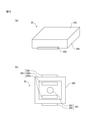
- FIG. 1 It is a perspective view of the switch which mounted the spring member which concerns on 1st Embodiment.
- A is a cross-sectional view taken along the line AA'shown in FIG. 1
- (b) is a cross-sectional view taken along the line AA' shown in FIG. 1 with the switch shown in FIG. 1 pressed.
- C is a cross-sectional view taken along the line BB'shown in FIG. 1
- (d) is a cross-sectional view taken along the line BB'shown in FIG. 1 with the switch shown in FIG. 1 pressed.
- Yes is a cross-sectional view taken along the line CC'shown in FIG.
- FIG. 1 is a cross-sectional view taken along the line CC'shown in FIG. 1 with the switch shown in FIG. 1 pressed.
- FIG. 1 It is an exploded perspective view of the switch shown in FIG. (A) is a perspective view of the spring member shown in FIG. 3, and (b) is a plan view of the spring member shown in FIG. (A) is a diagram showing the expansion of the dome portion when the spring member according to the comparative example is pressed, and (b) is a diagram showing the expansion of the dome portion 11 when the spring member shown in FIG. 3 is pressed.
- (C) is a diagram showing the distance between the dome portion and the outer edge of the spring member according to the comparative example
- (d) is a diagram showing the distance between the dome portion and the outer edge of the spring member shown in FIG. It is a figure which shows.
- (A) is a diagram showing a first step of the spring member manufacturing process shown in FIG. 3
- (b) is a diagram showing a second step of the spring member manufacturing process shown in FIG. 3
- (c) is a diagram. It is a figure which shows the 3rd process of the manufacturing process of the spring member shown in FIG.
- (A) is a perspective view of the spring member according to the second embodiment
- (b) is a plan view of the spring member shown in (a).
- (A) is a perspective view of the spring member according to the third embodiment, and (b) is a plan view of the spring member shown in (a).
- (A) is a perspective view of the spring member according to the fourth embodiment, and (b) is a plan view of the spring member shown in (a).
- (A) is a perspective view of the spring member according to the fifth embodiment, and (b) is a plan view of the spring member shown in (a).
- (A) is a perspective view of the spring member according to the sixth embodiment, and (b) is a plan view of the spring member shown in (a).
- (A) is a perspective view of the spring member according to the seventh embodiment, and (b) is a plan view of the spring member shown in (a).
- (A) is a perspective view of the spring member according to the eighth embodiment, and (b) is a plan view of the spring member shown in (a).
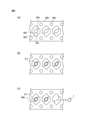
- (A) is a plan view of the spring member shown in FIG. 3 showing a region where the first side portion and the second side portion are formed, and (b) is a plan view of the spring member according to the first modification.
- (C) is a plan view of the spring member according to the second modification, (d) is a plan view of the spring member according to the third modification, and (e) is a plan view of the spring member according to the fourth modification.
- (f) is a plan view of the spring member which concerns on a 5th modification
- (g) is a plan view of a spring member which concerns on a 6th modification
- (h) is a plan view of the spring member which concerns on a 7th modification. It is a top view of a spring member.
- (A) is a plan view of the spring member according to the eighth modification
- (b) is a plan view of the spring member according to the ninth modification.
- (A) is a perspective view of the switch according to the modified example
- FIG. 1 is a perspective view of a switch equipped with a spring member according to the first embodiment.
- 2 (a) and 2 (b) are cross-sectional views taken along the line AA'shown in FIG. 1
- FIGS. 2 (c) and 2 (d) are cross-sectional views taken along the line BB'shown in FIG. 2 (e) and 2 (f) are cross-sectional views taken along the line CC'shown in FIG. 2 (b)
- 2 (d) and 2 (f) are cross-sectional views in a state where the switches shown in FIGS. 2 (a), 2 (c) and 2 (e) are pressed.
- FIG. 1 is a perspective view of a switch equipped with a spring member according to the first embodiment.
- 2 (a) and 2 (b) are cross-sectional views taken along the line AA'shown in FIG. 1
- FIGS. 2 (c) and 2 (d) are cross-sectional views taken along the line BB'shown in FIG. 2 (e
- FIG. 3 is an exploded perspective view of the switch shown in FIG.
- the mountain bending portion that is bent upward in a convex shape is indicated by a alternate long and short dash line
- the valley bending portion that is bent upward in a concave shape is indicated by a broken line.
- the switch 10 has a substrate 100, a first fixed contact 101, a second fixed contact 102, a spring member 1, a pressing member 103, a case member 104, and a protective cover 105.
- the substrate 100 is a flat plate-shaped member having a rectangular planar shape formed of an insulating resin material, and the first fixed contact 101 and the second fixed contact 102 are arranged on the surface thereof.
- a pair of electrodes electrically connected to each of the first fixed contact 101 and the second fixed contact 102 are arranged on the back surface of the substrate 100, and the switch 10 has a pair of electrodes arranged on the back surface of the substrate 100. It is connected to an external device such as a control device via the device.
- the first fixed contact 101 is a conductor having a circular planar shape arranged in the center of the surface of the substrate 100, and is arranged below the top of the spring member 1.
- the second fixed contact 102 is a conductor having a frame-shaped planar shape, and is arranged on the surface of the substrate 100 so as to surround the first fixed contact 101.
- the spring member 1 is a dome-shaped conductor arranged so that the end portion in the longitudinal direction is in contact with the second fixed contact 102 and the top portion is located above the first fixed contact 101. As shown by the arrow D in FIGS. 2 (b), 2 (d) and 2 (f), the spring member 1 reverses in response to the switch 10 being pressed from the surface direction, and the top thereof is first. Contact the fixed contact. When the top of the spring member 1 comes into contact with the first fixed contact 101, the connection between the first fixed contact 101 and the second fixed contact 102 becomes conductive, and the switch 10 is turned on. Further, when the top of the spring member 1 is not pressed, the first fixed contact 101 and the spring member 1 are separated from each other, and the first fixed contact 101 and the second fixed contact 102 are insulated from each other, the switch 10 is turned off. Will be.
- the pressing member 103 is made of a cylindrical resin material and is arranged above the top of the spring member 1. By arranging the pressing member 103, the operability of the pressing operation of the switch 10 is improved.
- the pressing member 103 may have a rectangular parallelepiped shape. Further, the pressing member 103 may be omitted.
- the case member 104 is a frame-shaped resin material, and by arranging the case member 104 on the substrate 100, the case member 104 has a storage portion for accommodating the first fixed contact 101, the second fixed contact 102, the spring member 1, and the pressing member 103. Form with 100.
- the case member 104 is adhered to the surface of the substrate 100 via an adhesive member such as an adhesive and an adhesive sheet.
- the case member has a frame shape, but it may have an elliptical shape.
- the protective cover 105 is a sheet material made of a flexible synthetic resin such as polyimide, and is adhered to the surface of the case member 104 so as to cover the storage portion formed by the substrate 100 and the case member 104.
- FIG. 4A is a perspective view of the spring member 1
- FIG. 4B is a plan view of the spring member 1.
- the mountain bend is indicated by a long-dot chain line
- the valley bend is indicated by a broken line.
- the spring member 1 includes a dome portion 11, a first side portion 12, a second side portion 13, a first support portion 14, a second support portion 15, a first bending portion 16, and a second bending portion 17. And a third bent portion 18 and a fourth bent portion 19.
- the dome portion 11 is a dome-shaped plane extending so that the first direction is longer than the second direction in each of the first direction which is the longitudinal direction and the second direction which is the short direction orthogonal to the first direction. It has a shape and has a shape that bulges in a third direction, that is, upward. When the dome portion 11 is pressed, the dome portion 11 reverses in the inner region of the first bent portion 16, the second bent portion 17, the third bent portion 18, and the fourth bent portion 19.
- the first side portion 12 is arranged in contact with the dome portion 11, the first support portion 14, and the second support portion 15 via the first bending portion 16.
- a third bent portion 18 and a fourth bent portion 19 extend in the vicinity of both ends of the first side portion 12. Further, at the contact points between the first side portion 12 and the dome portion 11 and the first support portion 14, the first bent portion 16 and the third bent portion 18 intersect, and the first side portion 12, the dome portion 11 and the second At the point of contact with the support portion 15, the first bent portion 16 and the fourth bent portion 19 intersect.
- the outer edge of the first side portion 12 extends in the first direction and has a linear straight portion 120, also referred to as a first straight portion.
- the second side portion 13 is arranged in contact with the dome portion 11, the first support portion 14, and the second support portion 15 via the second bent portion 17. Similar to the first side portion 12, the third bent portion 18 and the fourth bent portion 19 extend in the vicinity of both ends of the second side portion 13. Further, at the contact points between the second side portion 13 and the dome portion 11 and the first support portion 14, the second bent portion 17 and the third bent portion 18 intersect, and the second side portion 13, the dome portion 11 and the second At the point of contact with the support portion 15, the second bent portion 17 and the fourth bent portion 19 intersect.
- the outer edge of the second side portion 13 extends in the first direction parallel to the straight portion 120 and has a linear straight portion 130 also referred to as a second straight portion.
- the first support portion 14 is in contact with the dome portion 11 via the third bent portion 18, and is attached to each of the first side portion 12 and the second side portion 13 via the first bent portion 16 and the second bent portion 17. Placed in contact.
- the outer edge of the first support portion 14 has a pair of straight line portions 140, a pair of arc portions 141, and an end portion 142.
- the pair of straight line portions 140 extend continuously from each of the straight line portion 120 of the first side portion 12 and the straight line portion 130 of the second side portion 13.
- the pair of arc portions 141 extend in an arc shape from the ends of the straight portions 140 of the pair of straight portions, and come into contact with the second fixed contact 102.
- the end portion 142 connects between the other ends of the pair of arcuate portions 141.
- the second support portion 15 is in contact with the dome portion 11 via the fourth bent portion 19, and is attached to each of the first side portion 12 and the second side portion 13 via the first bent portion 16 and the second bent portion 17. Placed in contact.
- the outer edge of the second support portion 15 has a pair of straight portions 150, a pair of arc portions 151, and an end portion 152.
- the pair of straight line portions 150 extend continuously from each of the straight line portion 120 of the first side portion 12 and the straight line portion 130 of the second side portion 13.
- the pair of arc portions 151 extends in an arc shape from the ends of the straight portions 150 of the pair of straight portions, and come into contact with the second fixed contact 102.
- the end portion 152 connects between the other ends of the pair of arcuate portions 151.
- the first bent portion 16 and the second bent portion 17 are valley bent portions and are arranged between the dome portion 11 and the first side portion 12 and the second side portion 13.
- the first bent portion 16 and the second bent portion 17 extend in the first direction while bending inward between the outer edges extending linearly in the longitudinal direction of the spring member 1.
- the third bent portion 18 and the fourth bent portion 19 are mountain bent portions.
- the third bent portion 18 is arranged between the dome portion 11 and the first support portion 14, and the fourth bent portion 19 is arranged between the dome portion 11 and the second support portion 15.
- the outer edge of the first bending portion 16 and the minimum value W D of the second width between the second bent portion 17, the outer edge and a second side portion 13 of the first side 12 forming the outer edge of the dome portion 11 it is preferably less than is and 90% at least 60% of the distance W F between, is 70% in one embodiment.
- Distance W F between the minimum value W D of the second width is the outer edge of the outer edge and the second side portion 13 of the first side 12 between the first bent portion 16 and the second bent portion 17 60 If it is less than%, the size of the dome portion 11 becomes too small and the click feeling is lowered.
- the distance W F between the minimum value W D of the second width is the outer edge of the outer edge and the second side portion 13 of the first side 12 between the first bent portion 16 and the second bending portion 17
- the distance between the outer edge of the first side portion 12 and the outer edge of the second side portion 13 on which the cut surface is formed becomes shorter.
- the distance between the dome portion 11 and the outer edge of the first side portion 12 and the outer edge of the second side portion 13 becomes shorter, the outer edge of the first side portion 12 and the outer edge of the second side portion 13 are repeatedly pressed. There is a high risk of damage.
- FIG. 5A is a diagram showing the expansion of the dome portion when the spring member according to the comparative example is pressed
- FIG. 5B is a diagram showing the expansion of the dome portion 11 when the spring member 1 is pressed. It is a figure.
- FIG. 5C is a diagram showing the distance between the dome portion and the outer edge of the spring member according to the comparative example
- FIG. 5D is a diagram showing the distance between the dome portion and the outer edge of the spring member 1. Is.
- the spring member 900 has a dome portion 911, an outer peripheral portion 912, a first support portion 913, and a second support portion 914.
- the dome portion 911 has a substantially circular planar shape, and the outer peripheral portion 912 is arranged over the entire outer circumference of the dome portion 911 via a valley bending portion.
- the first support portion 913 and the second support portion 914 are arranged so as to face each other with the dome portion 911 interposed therebetween at the end portion in the longitudinal direction.
- the first support portion 913 and the second support portion 914 are arranged on the switch so as to be in contact with the fixed electrode.
- the dome portion 911 since the dome portion 911 has a perfect circular planar shape, the dome portion 911 spreads evenly over the entire circumference when pressed. Further, the spring member 900, the width of the outer peripheral portion 916, the dome portion 911 and the first supporting portion 913 and the outer green part 901 than the length W P1 of the dome portion 911 and the longitudinal direction between the second support portion 914 And the length W P2 between 902 is shorter.
- the magnitude of the stress applied when the spring member 900 is pressed gradually increases from the top to the outer peripheral edge.
- the stress applied when pressed is maximum in the outer peripheral green portions 901 and 902 in which the fracture surface is formed during punching, and by repeating pressing, the outer peripheral green portions 901 and 902 are subjected to repeated pressing. There is a high possibility that cracks will be formed.
- the dome portion 11 since the dome portion 11 has a planar shape in which each of the four corners is convex, the dome portion 11 has four corners larger than the inwardly curved side when pressed. Spreads to stretch. Further, in the spring member 1, when the dome portion 11 is pressed, the dome portion 11 reverses the inside of the first bending portion 16 and the second bending portion 17, which are valley bends, so that the dome portion 11 extends from the short side extending in the second direction. However, the long side extending in the first direction has a larger spread. In the spring member 1, the width of the first side 12 and second side 13, the length W S of the short direction, length in the lateral direction of the width of the outer peripheral portion 912 of the spring member 900 according to the comparative example It will be longer than W P2.
- the dome portion 11 can reduce the stress applied to the side of the dome portion 11 by expanding the four corners so as to greatly extend when pressed. Further, the length W s of the width of the first side portion 12 and the second side portion 13 of the spring member 1 in the lateral direction is larger than the length W P2 of the width of the outer peripheral portion 912 of the spring member 900 in the lateral direction. Since it is long, the stress applied to the straight portion 120 and the straight portion 130 can be further reduced.
- the straight portion 120 and the straight portion can be efficiently reduced.
- the spring member 1 since the first bent portion 16 to the fourth bent portion 19 reach the outer edge of the spring member 1, when the bent portion of the spring member 900 or the like is made smaller than the spring member that does not reach the outer edge. Is easy to process.
- the dome portion 11 since the dome portion 11 has a planar shape in which four corners extend in a convex shape, the dome portion 11 has a substantially circular planar shape, and the size is defined by the length in the lateral direction.
- the size can be made larger than 911.
- the spring member 1 since the spring member 1 has a planar shape in which the four corners of the dome portion 11 extend in a convex shape, the longitudinal direction and the lateral direction coincide with each other when a plurality of spring members 1 are superposed and arranged. It has a so-called self-alignment effect that can be arranged in. Since the spring member 1 has a self-alignment effect, even when the spring member 1 is superposed on the inside of the switch, the life is affected by the load generated by the eccentricity caused by the displacement of the superposed spring member in the longitudinal direction and the lateral direction. The risk of giving is low. In addition, since the dome portion has a deformed shape when superimposed, it also has an effect of preventing rotation.
- FIG. 6 (a) is a diagram showing a first step of the manufacturing process of the spring member 1
- FIG. 6 (b) is a diagram showing a second step of the manufacturing process of the spring member 1
- FIG. 6 (c) is a diagram. It is a figure which shows the 3rd process of the manufacturing process of a spring member 1.
- the coil material 200 which is a stainless steel having a plate thickness of 25 ⁇ m to 60 ⁇ m, is punched to form an outer shape portion 201 corresponding to the outer shape of the spring member 1.
- pilot holes 205 used for positioning are arranged side by side in the longitudinal direction.
- Drilling holes 202 and 203 are formed in the longitudinal direction of the external shape portion 201.
- both ends of the outer shape portion 201 in the longitudinal direction are connected to the coil material 200 via the connecting portion 204.
- the outer shape portion 201 is punched out of the coil material 200 so that the stretching direction in the longitudinal direction is inclined by, for example, 45 ° with respect to the rolling direction of the coil material 200.
- the angle at which the external shape portion 201 is punched out with respect to the rolling direction of the coil material 200 may be an angle other than 45 ° such as 0 ° or 90 °.
- the outer shape portion 201 is pressed to form the press shape portion 211 having a shape corresponding to each of the dome portion 11 to the fourth bent portion 19.
- the third bending portion 18 and the fourth bending portion which are mountain bending portions having relatively high strength, are formed.
- the press-shaped portion 211 is formed.
- the spring member 1 is formed by cutting the press-shaped portion 211 from the coil material 200 and disassembling it by cutting.
- FIG. 7 (a) is a perspective view of the spring member according to the second embodiment
- FIG. 7 (b) is a plan view of the spring member shown in FIG. 7 (a).
- the mountain bend is indicated by a long-dot chain line
- the valley bend is indicated by a broken line.
- the spring member 2 includes a dome portion 21, a first side portion 22, a second side portion 23, a first support portion 24, a second support portion 25, a first bending portion 26, and a second bending portion 27. And a third bent portion 28, and a fourth bent portion 29.
- the first bent portion 26 and the second bent portion 27 reach the outer edge of the spring member 2 at the arc portion instead of the straight portion in the longitudinal direction of the spring member 2.
- the spring member 2 is arranged so that the end portion in the longitudinal direction of the switch 10 is in contact with the second fixed contact 102 and the top portion is located above the first fixed contact 101. Further, the spring member 2 is formed by processing a coil material in the same manner as the spring member 1.
- the dome portion 21 has a dome-shaped planar shape extending in each of the first direction and the second direction so that the first direction is longer than the second direction, and the dome portion 21 has a third direction. It has a shape that bulges convexly toward. The length of the dome portion 21 in the first direction is longer than the length of the dome portion 11 in the first direction.
- the shape of the outer edge of the first side portion 22 is different from that of the first side portion 12. Since the configuration and function of the first side portion 22 other than the shape of the outer edge are the same as the configuration and function of the first side portion 12, detailed description thereof will be omitted here.
- the outer edge of the first side portion 22 extends in an arc shape from both ends of the linear straight portion 220 extending in the first direction and both ends of the straight portion 220 toward the first support portion 24 and the second support portion 25. It has a pair of arc portions 221 also referred to as one arc portion.
- the shape of the outer edge of the second side portion 23 is different from that of the second side portion 13. Since the configuration and function of the second side portion 23 other than the shape of the outer edge are the same as the configuration and function of the second side portion 13, detailed description thereof will be omitted here.
- the outer edge of the second side portion 23 extends in an arc shape from both ends of the linear straight portion 230 extending in the first direction and both ends of the straight portion 230 toward the first support portion 24 and the second support portion 25. It has a pair of arc portions 231 which are also referred to as two arc portions.
- the shape of the outer edge of the first support portion 24 is different from that of the first support portion 14. Since the configuration and function of the first support portion 24 other than the shape of the outer edge are the same as the configuration and function of the first support portion 14, detailed description thereof will be omitted here.
- the outer edge of the first support portion 24 has a pair of arc portions 241 and an end portion 242.
- the pair of arc portions 241 extend in an arc shape from one end of the arc portions 221 and the arc portions 231.
- the end portion 242 linearly connects between the other ends of the pair of arc portions 241.
- the shape of the outer edge of the second support portion 25 is different from that of the second support portion 15. Since the configuration and function of the second support portion 25 other than the shape of the outer edge are the same as the configuration and function of the second support portion 15, detailed description thereof will be omitted here.
- the outer edge of the second support portion 25 has a pair of arc portions 251 and an end portion 252.
- the pair of arc portions 251 extend in an arc shape from the other ends of the arc portions 221 and the arc portions 231.
- the end portion 252 linearly connects between the other ends of the pair of arc portions 251.
- Each of the first bent portion 26 and the second bent portion 27 is a valley bent portion, and is arranged between the dome portion 21 and the first side portion 22 and the second side portion 23.
- the first bent portion 26 and the second bent portion 27 extend in the first direction while bending inward between the outer edges of the spring member 2 extending in an arc shape.
- the third bent portion 28 and the fourth bent portion 29 are mountain bent portions.
- the third bent portion 28 is arranged between the dome portion 21 and the first support portion 24, and the fourth bent portion 29 is arranged between the dome portion 21 and the second support portion 25.
- FIG. 8 (a) is a perspective view of the spring member according to the third embodiment
- FIG. 8 (b) is a plan view of the spring member shown in FIG. 8 (a).
- the mountain bend is indicated by a long-dot chain line
- the valley bend is indicated by a broken line.
- the spring member 3 includes a dome portion 31, a first side portion 32, a second side portion 33, a first support portion 34, a second support portion 35, a first bending portion 36, and a second bending portion 37. And a third bent portion 38, and a fourth bent portion 39. Similar to the spring member 1, the spring member 3 is arranged so that the end portion in the longitudinal direction of the switch 10 is in contact with the second fixed contact 102 and the top portion is located above the first fixed contact 101. Further, the spring member 3 is formed by processing a coil material in the same manner as the spring member 1.
- the first bent portion 36 and the second bent portion 37 do not intersect with any of the third bent portion 38 and the fourth bent portion 39. Since the first bent portion 36 and the second bent portion 37 do not intersect the third bent portion 38 and the fourth bent portion 39, a part of the outer edge of the dome portion 31 reaches the outer edge in the longitudinal direction of the spring member 3.
- the first side portion 32 and the second side portion 33 differ from the first side portion 12 and the second side portion 13 in that the third bent portion 38 and the fourth bent portion 39 do not extend inward.
- the configurations and functions of the first side portion 32 and the second side portion 33, except that the third bent portion 38 and the fourth bent portion 39 do not extend inward, are the same as that of the first side portion 12 and the second side portion 13. Since it is the same as the configuration and function, detailed description is omitted here.
- the first support portion 34 contacts the dome portion 31 via the third bent portion 38. Further, since the outer edge of the dome portion 31 reaches the outer edge in the longitudinal direction of the spring member 3, the first support portion 34 does not contact the first side portion 32 and the second side portion 33.
- the second support portion 35 contacts the dome portion 31 via the fourth bent portion 39. Further, the second support portion 35 does not come into contact with the first side portion 32 and the second side portion 33, similarly to the first support portion 34.
- the first bent portion 36 and the second bent portion 37 are valley bent portions.
- the first bent portion 36 is arranged between the dome portion 31 and the first side portion 32, and the second bent portion 37 is arranged between the dome portion 31 and the second side portion 33.
- the third bent portion 38 and the fourth bent portion 39 are mountain bent portions.
- the third bent portion 38 is arranged between the dome portion 31 and the first support portion 34, and the fourth bent portion 39 is arranged between the dome portion 31 and the second support portion 35.
- FIG. 9 (a) is a perspective view of the spring member according to the fourth embodiment
- FIG. 9 (b) is a plan view of the spring member shown in FIG. 9 (a).
- the mountain bend is indicated by a long-dot chain line
- the valley bend is indicated by a broken line.
- the spring member 4 differs from the spring member 1 in that the dome portion 41, the first support portion 44, and the second support portion 45 are provided in place of the dome portion 11, the first side portion 14, and the second side portion 15. Further, the spring member 4 is different from the spring member 1 in that it has the fifth bent portion 46 and the sixth bent portion 47.
- the components and functions of the spring member 4 other than the dome portion 41, the first support portion 44, the second support portion 45, the fifth bent portion 46, and the sixth bent portion 47 are the same as those of the spring member 1. Since it is the same as the configuration and function of the components of, detailed description thereof will be omitted here.
- the spring member 4 does not have to have the first bent portion 16 and the second bent portion 17.
- the spring member 4 is arranged so that the end portion in the longitudinal direction is in contact with the second fixed contact 102 and the top portion is located above the first fixed contact 101 in the switch 10. Further, the spring member 4 is formed by processing a coil material in the same manner as the spring member 1.
- the dome portion 41 differs from the dome portion 11 in that recesses formed by the fifth bent portion 46 and the sixth bent portion 47 are formed at both ends in the longitudinal direction.
- the dome portion 41 is in contact with the first support portion 44 via the fifth bent portion 46 in addition to the first bent portion 16, the second bent portion 17, and the third bent portion 18, and the first bent portion 16 and the second bend are formed. It contacts the second support portion 45 via the sixth bent portion 47 in addition to the portion 17 and the third bent portion 18.
- the first support portion 44 has a convex portion formed between the dome portion 41 and the first support portion 44 by a fifth bent portion 46 formed so as to intersect the third bent portion 18. 1 It is different from the support portion 14.
- the second support portion 45 has a convex portion formed between the dome portion 41 and the second support portion 45 by the sixth bent portion 47 formed so as to intersect the fourth bent portion 19. 2 It is different from the support portion 15.
- the fifth bent portion 46 is a valley bent portion that extends in the second direction while bending between both ends of the end portion 142
- the sixth bent portion 47 is a second bent portion that bends between both ends of the end portion 152 and extends in the second direction. It is a valley bending portion extending in the direction.
- FIG. 10 (a) is a perspective view of the spring member according to the fifth embodiment
- FIG. 10 (b) is a plan view of the spring member shown in FIG. 10 (a).
- the mountain bend is indicated by a long-dot chain line
- the valley bend is indicated by a broken line.
- the spring member 5 includes a dome portion 51, a first support portion 54, a second support portion 55, a fifth bent portion 56, and a sixth bent portion 57 in a dome portion 41, a first support portion 44, a second support portion 45, and a second. It is different from the spring member 4 in that it has the 5 bent portion 46 and the 6th bent portion 47 in place of the spring member 4.
- the components and functions of the spring member 5 other than the dome portion 51, the first support portion 54, the second support portion 55, the fifth bent portion 56, and the sixth bent portion 57 are the spring members 4 having the same reference numerals. Since it is the same as the configuration and function of the components of, detailed description thereof will be omitted here.
- the spring member 5 does not have to have the first bent portion 16 and the second bent portion 17.
- the spring member 5 is arranged so that the end portion in the longitudinal direction is in contact with the second fixed contact 102 and the top portion is located above the first fixed contact 101 in the switch 10. Further, the spring member 5 is formed by processing a coil material in the same manner as the spring member 1.
- the fifth bent portion 56 is different from the fifth bent portion 46 in that it extends between a pair of arc portions 141 instead of both ends of the end portion 142, and the sixth bent portion 57 is not both ends of the end portion 152 but a pair of arc portions. Stretching between the portions 151 is different from the fifth bent portion 46.
- the shapes of the dome portion 51, the first support portion 54, and the second support portion 55 are such that the positions of the fifth bent portion 56 and the sixth bent portion 57 are different from those of the fifth bent portion 46 and the sixth bent portion 47.
- the shapes of the dome portion 41, the first support portion 44, and the second support portion 45 are different depending on the above.
- FIG. 11 (a) is a perspective view of the spring member according to the sixth embodiment
- FIG. 11 (b) is a plan view of the spring member shown in FIG. 11 (a).
- the valley bend is indicated by a broken line.
- the spring member 6 includes a dome portion 61, a first side portion 62, a second side portion 63, a first support portion 64, a second support portion 66, a first bending portion 66, and a second bending portion 67. And a third bent portion 68, and a fourth bent portion 69. Similar to the spring member 1, the spring member 6 is arranged so that the end portion in the longitudinal direction of the switch 10 is in contact with the second fixed contact 102 and the top portion is located above the first fixed contact 101. Further, the spring member 6 is formed by processing a coil material in the same manner as the spring member 1.
- the dome portion 61 has a dome-shaped planar shape extending in each of the first direction and the second direction so that the first direction is longer than the second direction, and the dome portion 61 has a dome-shaped planar shape extending in the third direction. It swells in a convex shape toward it.
- the dome portion 61 has a planar shape in which the ends of straight lines forming a cross are connected by a curved line that curves inward. The four corners of the dome portion 61 extend to the outer edge of the spring member 6.
- the first side portion 62 is arranged in contact with the dome portion 61 via the first bending portion 66 which is a valley bending portion.
- the outer edge of the first side portion 62 has a linear straight portion 620 extending in the first direction and a pair of arc portions 621 extending in an arc shape from both ends of the straight portion 620.
- the second side portion 63 is arranged in contact with the dome portion 61 via the second bending portion 67 which is a valley bending portion.
- the outer edge of the second side portion 63 has a linear straight portion 630 extending in the first direction and a pair of arc portions 631 extending in an arc shape from both ends of the straight portion 630.
- the first support portion 64 is arranged in contact with the dome portion 61 via the third bending portion 68 which is a valley bending portion.
- the outer edge of the first support portion 64 has an arc portion 641 extending in an arc shape from the arc portion 621 and the arc portion 631 through the corner of the dome portion 61, and when the spring member 6 is mounted on the switch 10, the outer edge thereof has an arc portion 641. Contact the second fixed contact 102.
- the second support portion 65 is arranged in contact with the dome portion 61 via the fourth bent portion 69, which is a valley bending portion.
- the outer edge of the second support portion 65 has an arc portion 651 extending in an arc shape from the arc portion 621 and the arc portion 631 through the corner of the dome portion 61, and when the spring member 6 is mounted on the switch 10, the second support portion 65 has an arc portion 651. Contact the second fixed contact 102.
- the first bent portion 66, the second bent portion 67, the third bent portion 68, and the fourth bent portion 69 are valley bent portions and are stretched while being curved inward.
- the first bent portion 66 is arranged between the dome portion 61 and the first side portion 62
- the second bent portion 67 is arranged between the dome portion 61 and the second side portion 63.
- the third bent portion 68 is arranged between the dome portion 61 and the first support portion 64
- the fourth bent portion 69 is arranged between the dome portion 61 and the second support portion 65.
- FIG. 12 (a) is a perspective view of the spring member according to the seventh embodiment
- FIG. 12 (b) is a plan view of the spring member shown in FIG. 12 (a).
- the valley bend is indicated by a broken line.
- the spring member 7 has a dome portion 71, a first side portion 72, a second side portion 73, a first support portion 74, a second support portion 75, and a bending portion 76. Similar to the spring member 1, the spring member 7 is arranged so that the end portion in the longitudinal direction of the switch 10 is in contact with the second fixed contact 102 and the top portion is located above the first fixed contact 101. Further, the spring member 7 is formed by processing a coil material in the same manner as the spring member 1.
- the dome portion 71 has a dome-shaped planar shape extending in each of the first direction and the second direction so that the first direction is longer than the second direction, and bulges convexly toward the third direction. It has a dome shape.
- the dome portion 71 has a planar shape in which the ends of the straight lines forming the cross are connected by a curved line that curves inward.
- the first side portion 72 and the second side portion 73 are arranged so as to extend in the first direction along the longitudinal direction of the dome portion 71 so as to include the side ends of the spring member 7. Since each of the first side portion 72 and the second side portion 73 is arranged so as to include the side ends of the spring member 7, they are both ends of the spring member 7 in the second direction, that is, in the lateral direction. Further, both the outer edges of the first side portion 72 and the second side portion 73 extend linearly in the first direction. Further, each of the bent portion 76 formed between the first side portion 72 and the second side portion 73 and the dome portion 71 extends in the first direction while being curved inward.
- Each of the first support portion 74 and the second support portion 75 has a planar shape on an arc, and each of both ends of the dome portion 71 in the first direction is bent inward and extends in the second direction. Arranged via 76.
- the first support portion 74 and the second support portion 75 are outer peripheral portions of the spring member 7 that form a continuous flat surface together with the first side portion 72 and the second side portion 73.
- the bent portion 76 is a valley bent portion arranged along the outer edge of the dome portion 71.
- the dome portion 71 can reduce the stress applied to the side of the dome portion 71 by expanding the four corners so as to greatly extend when pressed. Further, in the spring member 7, since the spread of the long side extending in the first direction is smaller than the spread of the short side, the stress applied in the longitudinal direction of the spring member 7 can be further reduced. Further, since the length in the longitudinal direction and the length in the lateral direction of the spring member 7 are longer than the length W P1 in the longitudinal direction and the length W P2 in the lateral direction of the width of the outer peripheral portion of the spring member 900, It is possible to further reduce the stress applied to the end portion of the outer peripheral portion where the fracture surface is formed in the lateral direction.
- the dome portion 71 since the dome portion 71 has a planar shape in which four corners extend in a convex shape, the dome portion whose size is defined by the length in the lateral direction because it has a substantially circular planar shape. It can be larger than 911. By making the size of the dome portion 71 larger than the size of the dome portion 911 according to the comparative example, the spring member 7 can realize a better click feeling with the same size.
- the spring member 7 since the spring member 7 has a planar shape in which the four corners of the dome portion 71 extend in a convex shape, the longitudinal direction and the lateral direction coincide with each other when a plurality of spring members 7 are superposed and arranged. It has a so-called self-alignment effect that can be arranged in. Since the spring member 7 has a self-alignment effect, even when the spring member 7 is superposed on the inside of the switch, the life is affected by the load generated by the eccentricity caused by the displacement of the superposed spring member in the longitudinal direction and the lateral direction. The risk of giving is low.
- FIG. 13 (a) is a perspective view of the spring member according to the eighth embodiment
- FIG. 13 (b) is a plan view of the spring member shown in FIG. 13 (a).
- the valley bend is indicated by a broken line.
- the spring member 8 is different from the spring member 7 in that the dome portion 81 is provided in place of the dome portion 71. Since the configurations and functions of the components of the spring member 8 other than the dome portion 81 are the same as the configurations and functions of the components of the spring member 7 having the same reference numerals, detailed description thereof will be omitted here.
- the spring member 8 is arranged so that the end portion in the longitudinal direction is in contact with the second fixed contact 102 and the top portion is located above the first fixed contact 101 in the switch 10. Further, the spring member 8 is formed by processing a coil material in the same manner as the spring member 1.
- the dome portion 81 has a shape in which the valley bending portion 86 extends linearly in the lateral direction of the spring member 8 so that the end portion in the longitudinal direction bends outward and extends in the lateral direction. It is different from 71.
- the first bent portion and the second bent portion are curved in an arc shape and stretched in the first direction, but in the spring member according to the embodiment, the first bent portion and the second bent portion are formed.
- the shape of is not limited to the arc shape.
- the shape of the first bent portion and the second bent portion may be a trapezoid with the outer edge as the lower base, or a shape in which the trapezoidal legs having the outer edge as the lower base are replaced with curves curved in an arc shape. It may be a shape in which the upper base of the trapezoid having the outer edge as the lower base is replaced with a curved curve in an arc shape.
- the outer edges of the first side portion and the second side portion have a straight portion extending in the longitudinal direction, but in the spring member according to the embodiment, the first side portion and the second side portion.
- the outer edge of the may have an arcuate portion that curves outward instead of a straight line portion.
- the curvature of the arc is greater than the curvature of the virtual circle that touches at least three points on the outer edge of the spring member.
- each of the first bent portion and the second bent portion extends to the outer edge of the spring member.
- the first bent portion and the second bent portion are located in the vicinity of the central portion between the first support portion and the second support portion, and in the first side portion and the second side portion. If they are arranged in close proximity, they do not have to extend to the outer edge of the spring member.
- FIG. 14A is a plan view of the spring member 1 showing a region where the first side portion and the second side portion are formed.
- the spring member 1 is provided by the first row line LC1 and the second row line LC2 in the first row region RC1 including the first side portion 12, the second row region RC2 including the second side portion 13, and the first row region RC1. It is divided into a third row region RC3 between and the second row region RC2.
- the first row region RC1, the second row region RC2, and the third row region RC3 have the first row line LC1 so that the widths of the first row region RC1, the second row region RC2, and the third row region RC3 are uniform. And divided by the second row line LC2.
- the spring member 1 has the first row region RR1 including the first support portion 14, the second row region RR2 including the second support portion 15, and the first row by the first row line LR1 and the second row line LR2. It is divided into a third row region RR3 between the region RR1 and the second row region RR2. In the first row region RR1, the second row region RR2, and the third row region RR3, the widths of the first row region RR1, the second row region RR2, and the third row region RR3 are uniform so that the width of the first row region RR1 is uniform. And the second line LR2.
- the first bent portion 16 is formed in the first row region RC1 and is not formed in the third row region RC3, and the second bent portion 17 is formed in the second row region RC2 and not in the third row region RC3. .. Further, the first bent portion 16 and the second bent portion 17 are formed in at least the third row region RR3. In the spring member 1, the first bending portion 16 and the second bending portion 17 are formed in the first row region RR1 and the second row region RR2 in addition to the third row region RR3.
- the spring member 1 may have a reduced click feeling. Further, if the first bent portion 16 and the second bent portion 17 are not formed in the third row region RR3, there is a high possibility that cracks will occur in the first side portion 12 and the second side portion 13.
- FIG. 14 (b) is a plan view of the spring member according to the first modification
- FIG. 14 (c) is a plan view of the spring member according to the second modification
- FIG. 14 (d) is a third modification
- 14 (e) is a plan view of the spring member according to the fourth modification
- FIG. 14 (e) is a plan view of the spring member according to the fourth modification
- 14 (f) is a plan view of the spring member according to the fifth modification
- FIG. 14 (g) is a plan view of the spring member according to the sixth modification
- FIG. 14 (h) is a seventh modification. It is a top view of the spring member which concerns on.
- the first bent portion 16a and the second bent portion 17a formed on the spring member 1a extend while bending inward, but do not extend to the outer edge of the spring member 1a.
- the first bent portion 16a is formed in the first row region RC1 and is not formed in the third row region RC3, and the second bent portion 17a is formed in the second row region RC2 and not in the third row region RC3. ..
- the first bent portion 16a and the second bent portion 17a are formed in the third row region RR3, and are not formed in the first row region RR1 and the second row region RR2.
- the first bent portion 16b and the second bent portion 17b formed on the spring member 1b extend while bending inward, but do not extend to the outer edge of the spring member 1b.
- the first bent portion 16b and the second bent portion 17b are formed in a region closer to the first side portion 12 and the second side portion 13 than the first bent portion 16a and the second bent portion 17a.
- the first bent portion 16a is formed in the first row region RC1 and is not formed in the third row region RC3, and the second bent portion 17a is formed in the second row region RC2 and not in the third row region RC3. ..
- the first bent portion 16b and the second bent portion 17b are formed in the third row region RR3, and are not formed in the first row region RR1 and the second row region RR2.
- the first bent portion 16a and the second bent portion 17a formed on the spring member 1c extend linearly from the third bent portion 18 toward the fourth bent portion 19, but do not extend to the outer edge of the spring member 1c.
- the first bent portion 16a is formed in the first row region RC1 and is not formed in the third row region RC3, and the second bent portion 17a is formed in the second row region RC2 and not in the third row region RC3. ..
- the first bent portion 16c and the second bent portion 17c are formed in the third row region RR3, and are not formed in the first row region RR1 and the second row region RR2.
- the first bent portion 16d and the second bent portion 17d formed on the spring member 1d extend while bending inward, but do not extend to the outer edge of the spring member 1d.
- the first bent portion 16d and the second bent portion 17d intersect the third bent portion 18 and the fourth bent portion 19.
- the first bent portion 16d is formed in the first row region RC1 and is not formed in the third row region RC3, and the second bent portion 17d is formed in the second row region RC2 and not in the third row region RC3. ..
- the first bending portion 16d and the second bending portion 17d are formed in the first row region RR1 and the second row region RR2 in addition to the third row region RR3.
- the first bent portion 16e and the second bent portion 17e formed on the spring member 1e extend while bending inward, but do not extend to the outer edge of the spring member 1e.
- the first bent portion 16e and the second bent portion 17e do not intersect the third bent portion 18 and the fourth bent portion 19.
- the first bent portion 16e is formed in the first row region RC1 and is not formed in the third row region RC3, and the second bent portion 1ed is formed in the second row region RC2 and not in the third row region RC3. ..
- the first bending portion 16e and the second bending portion 17e are formed in the first row region RR1 and the second row region RR2 in addition to the third row region RR3.
- the first bent portion 16f and the second bent portion 17f formed on the spring member 1f extend while bending inward, but do not extend to the outer edge of the spring member 1f.
- the first bent portion 16f and the second bent portion 17f do not intersect the third bent portion 18 and the fourth bent portion 19.
- the first bent portion 16f and the second bent portion 17f are formed in a region closer to the first side portion 12 and the second side portion 13 than the first bent portion 16e and the second bent portion 17e.
- the first bent portion 16f is formed in the first row region RC1 and is not formed in the third row region RC3, and the second bent portion 1fd is formed in the second row region RC2 and not in the third row region RC3. ..
- the first bending portion 16f and the second bending portion 17f are formed in the first row region RR1 and the second row region RR2 in addition to the third row region RR3.
- the first bent portion 16 g and the second bent portion 17 g formed on the spring member 1 g extend linearly from the third bent portion 18 toward the fourth bent portion 19, but do not extend to the outer edge of the spring member 1 g.
- the first bent portion 16 g and the second bent portion 17 g do not intersect the third bent portion 18 and the fourth bent portion 19.
- the first bent portion 16 g is formed in the first row region RC1 and is not formed in the third row region RC3, and the second bent portion 17 g is formed in the second row region RC2 and not in the third row region RC3. ..
- the first bending portion 16g and the second bending portion 17g are formed in the first row region RR1 and the second row region RR2 in addition to the third row region RR3.
- the first bent portion 16 and the second bent portion 17 are formed so as to be curved over the entire surface, but in the spring member according to the embodiment, the first bent portion and the second bent portion are formed. May be stretched while a part is curved and the other part may be stretched linearly. Further, in the spring member 1, a single first bent portion 16 and a second bent portion 17 are formed, but in the spring member according to the embodiment, a plurality of first bent portions and second bent portions are formed. May be good.
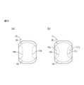
- FIG. 15A is a plan view of the spring member according to the eighth modification
- FIG. 15B is a plan view of the spring member according to the ninth modification. Since the configuration and function of the spring member 1h according to the eighth modification and the spring member 1i according to the ninth modification other than the first bending portion and the second bending portion are the same as the configuration and function of the spring member 1, details are given here. The explanation is omitted.
- the first bent portion 16h and the second bent portion 17h formed on the spring member 1h are stretched while being curved inward, and are also stretched to the outer edge of the spring member 1h. Both ends of the first bent portion 16h and the second bent portion 17h extend to the outer edge of the spring member 1h while bending. On the other hand, the central portion of the first bent portion 16h and the second bent portion 17h extends linearly. The first bent portion 16h and the second bent portion 17h extend to the outer edge of the spring member 1h.
- the spring member 1i is formed with two first bending portions 16i and 16j and two second bending portions 17i and 17j.
- the two first bent portions 16i and 16j are arranged in parallel on the first side portion 12 in the stretching direction.
- the two second bent portions 17i and 17j are arranged in parallel on the second side portion 13 in the stretching direction.
- the first fixed contact 101, the second fixed contact 102 and the spring member 1 are arranged in the accommodating portion formed by the rectangular flat plate-shaped substrate 100 and the case member 104.
- the accommodating portion may be formed by the lead frame.
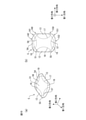
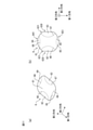
- FIG. 16 (a) is a perspective view of the switch according to the modified example
- FIG. 16 (b) is a plan view of the lead frame shown in FIG. 16 (a)
- FIG. 17 is a plan view of the switch shown in FIG. 16 (a). It is an exploded perspective view.
- the switch 20 is different from the switch 10 in that the switch 20 has a base 300, a first lead 301, and a second lead 302 instead of the substrate 100, the first fixed contact 101, the second fixed contact 102, and the case member 104. Since the configurations and functions of the components of the switch 20 other than the base 300, the first lead 301, and the second lead 302 are the same as the configurations and functions of the components of the switch 10 having the same reference numerals, detailed description thereof will be given here. Is omitted.
- the base 300 is formed of a mold resin such as an epoxy resin, is filled between the first lead 301 and the second lead 302, and accommodates the first fixed contact, the second fixed contact, and the spring member 1. Form a part.
- a mold resin such as an epoxy resin
- the first lead 301 has a first fixed contact 303 and a first electrode 304 integrally formed with the first fixed contact 303.
- the second lead 302 has a pair of second fixed contacts 305a and 305b and a second electrode 306 integrally formed with the pair of second fixed contacts 305a and 305b.
Landscapes
- Push-Button Switches (AREA)
Abstract
バネ部材は、上に向かって凸状となるドーム型のドーム部と、ドーム部を挟むように配置された第1側部及び第2側部と、ドーム部を挟み、且つ、第1側部及び第2側部のそれぞれの一端に接するように配置された第1支持部及び第1側部及び第2側部のそれぞれの他端に接するように配置された第2支持部と、ドーム部と第1側部との間に形成された第1曲げ部と、ドーム部と第2側部との間に形成された第2曲げ部と、ドーム部と第1支持部との間に形成された第3曲げ部と、ドーム部と第2支持部との間に形成された第4曲げ部と、を有する。
Description
本開示は、バネ部材及びスイッチに関する。
ドーム部が押下されることに応じて反転動作するバネ部材を可動接点とするプッシュ式のスイッチが知られている。プッシュ式のスイッチの可動接点として使用されるバネ部材は、タクトバネとも称される。プッシュ式のスイッチでは、バネ部材のドーム部が押下されて反転動作して基板に配置される固定接点に接することで、スイッチはオン状態となる。また、バネ部材のドーム部が押下されなくなり、基板に配置される固定接点から離隔すると、スイッチはオフ状態となる。
バネ部材は、コイル材を打ち抜き加工して形成されるが、コイル材を打ち抜き加工してバネ部材を形成するときに、バネ部材の外周緑部に破断面が形成される。スイッチのバネ部材は、押下により反転動作する毎に、破断面が形成される外周緑部に応力が印加されることで、破断面が形成された外周緑部からバネ部材の内側に向けてクラックが形成されることがある。
バネ部材の外周緑部から内側に向けてクラックが形成されることを防止するための種々の技術が知られている。例えば、特開2016-181365号公報には、ドーム部の中央部を挟んでドーム部の長手方向に沿って2ヶ所に突状部を延設させたバネ部材が記載されている。特開2016-181365号公報に記載されるバネ部材は、ドーム部の中央部を挟んでドーム部の長手方向に沿って2ヶ所に延設された突状部を有するので、外周端部における内部応力の集中を低減でき、外周端部におけるクラックの発生が低減されて、長寿命化を図ることができる。
しかしながら、特開2016-181365号公報に記載されるバネ部材は、突状部を形成する工程が複雑になり、製造コストが上昇するおそれがある。
本開示は、容易に製造可能であり、且つ、耐久性に優れたバネ部材を提供することを目的とする。
本に係るバネ部材は、上に向かって凸状となるドーム型のドーム部と、ドーム部を挟むように配置された第1側部及び第2側部と、ドーム部を挟み、且つ、第1側部及び第2側部のそれぞれの一端に接するように配置された第1支持部及び第1側部及び第2側部のそれぞれの他端に接するように配置された第2支持部と、ドーム部と第1側部との間に形成された第1曲げ部と、ドーム部と第2側部との間に形成された第2曲げ部と、ドーム部と第1支持部との間に形成された第3曲げ部と、ドーム部と第2支持部との間に形成された第4曲げ部と、を有する。
さらに、本開示に係るバネ部材では、第1側部と第2側部との間を、第1側部を含む第1列領域、第2側部を含む第2列領域、及び第1列領域と第2列領域との間の第3列領域に、第1列領域、第2列領域及び第3列領域の幅が均一になるように分割したときに、第1曲げ部は第1列領域に形成され且つ第3列領域には形成されず、第2曲げ部は第2列領域に形成され且つ第3列領域には形成されないことが好ましい。
さらに、本開示に係るバネ部材では、第1支持部と第2支持部との間を、第1支持部を含む第1行領域、第2支持部を含む第2行領域、及び第1行領域と第2行領域との間の第3行領域に、第1行領域、第2行領域及び第3行領域の幅が均一になるように分割したときに、第1曲げ部及び第2曲げ部は、少なくとも第3行領域に形成されることが好ましい。
さらに、本開示に係るバネ部材では、第1曲げ部及び第2曲げ部は、内側に湾曲しながら延伸することが好ましい。
さらに、本開示に係るバネ部材では、第1側部の外縁は、直線状に延伸する第1直線部を有し、第2側部の外縁は、第1直線部に平行に延伸する第2直線部を有することが好ましい。
さらに、本開示に係るバネ部材では、第1側部の外縁は、第1直線部の両端から第1支持部及び第2支持部のそれぞれに向かって円弧状に延伸する一対の第1円弧部を更に有し、第2側部の外縁は、第2直線部の両端から第1支持部及び第2支持部のそれぞれに向かって円弧状に延伸する一対の第2円弧部を更に有することが好ましい。
さらに、本開示に係るバネ部材では、第3曲げ部及び第4曲げ部は、外側に湾曲しながら延伸することが好ましい。
さらに、本開示に係るバネ部材では、第1曲げ部及び第2曲げ部は、上に向かって凹状に屈曲された谷曲げであり、第3曲げ部及び第4曲げ部は、上に向かって凸状に屈曲された山曲げであることが好ましい。
さらに、本開示に係るバネ部材では、第1曲げ部及び第2曲げ部のそれぞれは、第3曲げ部及び第4曲げ部の双方と交差することが好ましい。
さらに、本開示に係るバネ部材では、第1曲げ部、第2曲げ部、第3曲げ部及び第4曲げ部は、上に向かって凹状に屈曲された谷曲げであることが好ましい。
さらに、本開示に係るバネ部材では、第1曲げ部及び第2曲げ部のそれぞれは、第3曲げ部及び第4曲げ部の何れとも交差しないことが好ましい。
また、本開示に係るスイッチは、基板と、基板上に配置された第1固定接点と、第1固定接点の周囲に配置された第2固定接点と、長手方向の端部が第2固定接点に接すると共に、頂部が第1固定接点の上方に位置するように配置されたドーム状のバネ部材と、基板上に配置されることで、第1固定接点、第2固定接点、及びバネ部材1を収容する収納部を基板と共に形成するケース部材と、収納部を覆うようにケース部材の表面に接着される保護カバーと、を有し、バネ部材は、上に向かって凸状となるドーム型のドーム部と、ドーム部を挟むように配置された第1側部及び第2側部と、ドーム部を挟み、且つ、第1側部及び第2側部のそれぞれの一端に接するように配置された第1支持部及び第1側部及び第2側部のそれぞれの他端に接するように配置された第2支持部と、ドーム部と第1側部との間に形成された第1曲げ部と、ドーム部と第2側部との間に形成された第2曲げ部と、ドーム部と第1支持部との間に形成された第3曲げ部と、ドーム部と第2支持部との間に形成された第4曲げ部と、を有する。
さらに、本開示に係るスイッチは、第1固定接点、及び第1固定接点と一体的に形成された第1電極を有する第1リードと、第2固定接点、及び第2固定接点と一体的に形成された第2電極を有する第2リードと、を更に有し、基板は、第1リードと第2リードとの間に充填された樹脂材によって形成されることが好ましい。
また、本開示に係るバネ部材は、上に向かって凸状となるドーム型のドーム部と、ドーム部を挟むように配置された第1側部及び第2側部と、ドーム部を挟み、且つ、第1側部及び第2側部のそれぞれの一端に接するように配置された第1支持部及び第1側部及び第2側部のそれぞれの他端に接続するように配置された第2支持部と、ドーム部と第1支持部との間に形成された第3曲げ部と、ドーム部と第2支持部との間に形成された第4曲げ部と、ドーム部と第1支持部との間に、第3曲げ部と交差するように形成された第5曲げ部と、ドーム部と第2支持部との間に、第4曲げ部と交差するように形成された第6曲げ部とを有する。
本開示に係るバネ部材は、製造が容易であると共に、高い耐久性を有する。
以下、本開示に係るバネ部材及びバネ部材を有するスイッチについて図を参照しつつ説明する。但し、本開示の技術的範囲はそれらの実施の形態に限定されず、請求の範囲に記載された発明とその均等物に及ぶ点に留意されたい。
<第1実施形態に係るバネ部材を搭載したスイッチの構成及び機能>
図1は、第1実施形態に係るバネ部材を搭載したスイッチの斜視図である。図2(a)及び2(b)は図1に示すA-A‘線に沿う断面図であり、図2(c)及び2(d)は図1に示すB-B‘線に沿う断面図であり、図2(e)及び2(f)は図1に示すC-C‘線に沿う断面図である。図2(b)、2(d)及び2(f)は、図2(a)、2(c)及び2(e)のそれぞれに示すスイッチが押下された状態の断面図である。図3は、図1に示すスイッチの分解斜視図である。図3において、上に向かって凸状に屈曲される山曲げ部は一点鎖線で示され、上に向かって凹状に屈曲される谷曲げ部は破線で示される。
図1は、第1実施形態に係るバネ部材を搭載したスイッチの斜視図である。図2(a)及び2(b)は図1に示すA-A‘線に沿う断面図であり、図2(c)及び2(d)は図1に示すB-B‘線に沿う断面図であり、図2(e)及び2(f)は図1に示すC-C‘線に沿う断面図である。図2(b)、2(d)及び2(f)は、図2(a)、2(c)及び2(e)のそれぞれに示すスイッチが押下された状態の断面図である。図3は、図1に示すスイッチの分解斜視図である。図3において、上に向かって凸状に屈曲される山曲げ部は一点鎖線で示され、上に向かって凹状に屈曲される谷曲げ部は破線で示される。
スイッチ10は、基板100と、第1固定接点101と、第2固定接点102と、バネ部材1と、押圧部材103と、ケース部材104と、保護カバー105とを有する。
基板100は、絶縁性樹脂材料により形成された矩形の平面形状を有する平板状の部材であり、表面に第1固定接点101及び第2固定接点102が配置される。基板100の裏面には、第1固定接点101及び第2固定接点102のそれぞれに電気的に接続される一対の電極が配置され、スイッチ10は、基板100の裏面に配置される一対の電極を介して制御装置等の外部装置に接続される。
第1固定接点101は、基板100の表面の中心部に配置される円形状の平面形状を有する導体であり、バネ部材1の頂部の下方に配置される。第2固定接点102は、枠状の平面形状を有する導体であり、第1固定接点101を囲むように基板100の表面に配置される。
バネ部材1は、長手方向の端部が第2固定接点102に接すると共に、頂部が第1固定接点101の上方に位置するように配置されたドーム状の導体である。バネ部材1は、図2(b)、2(d)及び2(f)に矢印Dで示されるように、スイッチ10が表面方向から押下されることに応じて反転動作して頂部が第1固定接点に接する。バネ部材1の頂部が第1固定接点101に接することにより、第1固定接点101と第2固定接点102との間が導通して、スイッチ10がオンする。また、バネ部材1の頂部が押下されなくなり、第1固定接点101とバネ部材1とが離隔して、第1固定接点101と第2固定接点102との間が絶縁すると、スイッチ10はオフ状態となる。
押圧部材103は、円柱形状の樹脂材料で形成され、バネ部材1の頂部の上方に配置される。押圧部材103を配置することで、スイッチ10の押下操作の操作性が向上する。なお、実施形態に係るスイッチでは、押圧部材103は、直方体形状でもよい。また、押圧部材103は、省略されてもよい。
ケース部材104は、枠状の樹脂材料であり、基板100上に配置されることで、第1固定接点101、第2固定接点102、バネ部材1、及び押圧部材103を収容する収納部を基板100と共に形成する。ケース部材104は、接着剤及び接着シート等の接着部材を介して基板100の表面に接着される。本実施例では、ケース部材を枠状としたが、楕円形状でもよい。
保護カバー105は、ポリイミド等の可とう性を有する合成樹脂で形成されたシート材であり、基板100及びケース部材104によって形成された収納部を覆うようにケース部材104の表面に接着される。
<第1実施形態に係るバネ部材の構成及び機能>
図4(a)はバネ部材1の斜視図であり、図4(b)はバネ部材1の平面図である。図4(a)及び4(b)において、山曲げ部は一点鎖線で示され、谷曲げ部は破線で示される。
図4(a)はバネ部材1の斜視図であり、図4(b)はバネ部材1の平面図である。図4(a)及び4(b)において、山曲げ部は一点鎖線で示され、谷曲げ部は破線で示される。
バネ部材1は、ドーム部11と、第1側部12と、第2側部13と、第1支持部14と、第2支持部15と、第1曲げ部16と、第2曲げ部17と、第3曲げ部18と、第4曲げ部19とを有する。ドーム部11は、長手方向である第1方向及び第1方向と直交する短手方向である第2方向のそれぞれに、第2方向よりも第1方向が長くなるように延伸するドーム形状の平面形状を有し、第3方向すなわち上に向かって凸状に膨らんだ形状を有する。ドーム部11は、押下されたときに、第1曲げ部16、第2曲げ部17、第3曲げ部18及び第4曲げ部19の内側の領域で反転動作する。
第1側部12は、第1曲げ部16を介してドーム部11、第1支持部14及び第2支持部15に接して配置される。第1側部12の両端の近傍には、第3曲げ部18及び第4曲げ部19が延伸する。また、第1側部12とドーム部11及び第1支持部14との接点では、第1曲げ部16と第3曲げ部18とが交差し、第1側部12とドーム部11及び第2支持部15との接点では、第1曲げ部16と第4曲げ部19とが交差する。第1側部12の外縁は、第1方向に延伸し、第1直線部とも称される直線状の直線部120を有する。
第2側部13は、第2曲げ部17を介してドーム部11、第1支持部14及び第2支持部15に接して配置される。第2側部13の両端の近傍には、第1側部12と同様に、第3曲げ部18及び第4曲げ部19が延伸する。また、第2側部13とドーム部11及び第1支持部14との接点では、第2曲げ部17と第3曲げ部18とが交差し、第2側部13とドーム部11及び第2支持部15との接点では、第2曲げ部17と第4曲げ部19とが交差する。第2側部13の外縁は、直線部120に平行に第1方向に延伸し、第2直線部とも称される直線状の直線部130を有する。
第1支持部14は、第3曲げ部18を介してドーム部11に接すると共に、第1曲げ部16及び第2曲げ部17を介して第1側部12及び第2側部13のそれぞれに接して配置される。第1支持部14の外縁は、一対の直線部140と、一対の円弧部141と、端部142とを有する。一対の直線部140は、第1側部12の直線部120及び第2側部13の直線部130のそれぞれから連続して延伸する。一対の円弧部141は、一対の直線部の直線部140の端部から円弧状に延伸し、第2固定接点102に接触する。端部142は、一対の円弧部141の他端の間を接続する。
第2支持部15は、第4曲げ部19を介してドーム部11に接すると共に、第1曲げ部16及び第2曲げ部17を介して第1側部12及び第2側部13のそれぞれに接して配置される。第2支持部15の外縁は、一対の直線部150と、一対の円弧部151と、端部152とを有する。一対の直線部150は、第1側部12の直線部120及び第2側部13の直線部130のそれぞれから連続して延伸する。一対の円弧部151は、一対の直線部の直線部150の端部から円弧状に延伸し、第2固定接点102に接触する。端部152は、一対の円弧部151の他端の間を接続する。
第1曲げ部16及び第2曲げ部17は、谷曲げ部であり、ドーム部11と第1側部12及び第2側部13との間に配置される。第1曲げ部16及び第2曲げ部17は、バネ部材1の長手方向に直線状に延伸する外縁の間を内側に湾曲しながら第1方向に延伸する。
第3曲げ部18及び第4曲げ部19は、山曲げ部である。第3曲げ部18はドーム部11と第1支持部14との間に配置され、第4曲げ部19はドーム部11と第2支持部15との間に配置される。
ドーム部11の外縁を形成する第1曲げ部16と第2曲げ部17との間の第2方向の幅の最小値WDは、第1側部12の外縁と第2側部13の外縁との間の距離WFの60%以上であり且つ90%未満が好ましく、一態様では70%である。第1曲げ部16と第2曲げ部17との間の第2方向の幅の最小値WDが第1側部12の外縁と第2側部13の外縁との間の距離WFの60%未満であると、ドーム部11の大きさが小さくなり過ぎてクリック感が低下する。第1曲げ部16と第2曲げ部17との間の第2方向の幅の最小値WDが第1側部12の外縁と第2側部13の外縁との間の距離WFの90%より大きくなると、切断面が形成される第1側部12の外縁及び第2側部13の外縁との間の距離が短くなる。ドーム部11と第1側部12の外縁及び第2側部13の外縁との間の距離が短くなると、第1側部12の外縁及び第2側部13の外縁は、押下動作の繰り返しにより破損するおそれが高くなる。
図5(a)は比較例に係るバネ部材が押下されたときのドーム部の広がりを示す図であり、図5(b)はバネ部材1が押下されたときのドーム部11の広がりを示す図である。図5(c)は比較例に係るバネ部材のドーム部と外縁との間の距離を示す図であり、図5(d)はバネ部材1のドーム部と外縁との間の距離を示す図である。
比較例に係るバネ部材900は、ドーム部911と、外周部912と、第1支持部913と、第2支持部914とを有する。ドーム部911は、略真円状の平面形状を有し、外周部912は谷曲げ部を介してドーム部911の外周の全体に亘って配置される。第1支持部913及び第2支持部914は、長手方向の端部にドーム部911を挟んで対向するように配置される。第1支持部913及び第2支持部914は、固定電極に接するようにスイッチに配置される。
バネ部材900では、ドーム部911が真円状の平面形状を有するので、ドーム部911は、押下されたときに、全周に亘って均等に広がる。また、バネ部材900では、外周部916の幅は、ドーム部911と第1支持部913及び第2支持部914との間の長さWP1よりもドーム部911と長手方向の外周緑部901及び902との間の長さWP2の方が短くなる。
このため、バネ部材900は、押下されたときに、頂部から外周縁部に向かうに従って、押下されたときに印加される応力の大きさが徐々に大きくなる。バネ部材900では、押下されたときに印加される応力は、打ち抜き加工時に破断面が形成された長手方向の外周緑部901及び902において最大となり、押下を繰り返すことで外周緑部901及び902にクラックが形成される可能性が高くなる。
一方、バネ部材1では、ドーム部11が4つの角のそれぞれが凸状となる平面形状を有するので、ドーム部11は、押下されたときに、内側に湾曲する辺よりも4つの角が大きく伸びるように広がる。また、バネ部材1では、ドーム部11は、押下されたときに、谷曲げである第1曲げ部16及び第2曲げ部17の内側で反転動作するため、第2方向に延伸する短辺よりも第1方向に延伸する長辺の方が広がりが大きい。バネ部材1では、第1側部12及び第2側部13の幅は、短手方向の長さWSが、比較例に係るバネ部材900の外周部912の幅の短手方向の長さWP2よりも長くなる。
バネ部材1では、ドーム部11は、押下されたときに、4つの角が大きく伸びるように広がることでドーム部11の辺に印加される応力を低減できる。また、バネ部材1の第1側部12及び第2側部13の幅の短手方向の長さWsは、バネ部材900の外周部912の幅の短手方向の長さWP2よりも長いので、直線部120及び直線部130に印加される応力を更に低減できる。
また、バネ部材1では、谷曲げ部である第1曲げ部16及び第2曲げ部17が長手方向に延伸する直線部の端部においてバネ部材1の外縁に達するので、直線部120及び直線部130に印加される応力を効率的に低減できる。
また、バネ部材1では、第1曲げ部16~第4曲げ部19がバネ部材1の外縁に達するので、バネ部材900等の曲げ部が外縁まで達していないバネ部材よりも小型化されたときの加工が容易になる。
また、バネ部材1では、ドーム部11は4つの角が凸状に延伸する平面形状を有するため、略円形状の平面形状を有し、短手方向の長さによりサイズが規定されるドーム部911よりもサイズを大きくすることができる。バネ部材1は、ドーム部11のサイズを比較例に係るドーム部911のサイズよりも大きくすることで、同一サイズでより良好なクリック感を実現できる。
また、バネ部材1は、ドーム部11が4つの角が凸状に延伸する平面形状を有するため、複数のバネ部材1を重畳して配置するときに、長手方向及び短手方向が一致するように配置することができる、いわゆるセルフアライメント効果を有する。バネ部材1は、セルフアライメント効果を有するので、スイッチ内部に重畳して配置した場合でも、重畳されたバネ部材の長手方向及び短手方向がずれることで偏心したことにより生じる負荷により寿命に影響を与えるおそれは低い。また、重畳した時、ドーム部が異形形状になっているので、回転防止としての効果もある。
<第1実施形態に係るバネ部材の製造方法>
図6(a)はバネ部材1の製造工程の第1工程を示す図であり、図6(b)はバネ部材1の製造工程の第2工程を示す図であり、図6(c)はバネ部材1の製造工程の第3工程を示す図である。
図6(a)はバネ部材1の製造工程の第1工程を示す図であり、図6(b)はバネ部材1の製造工程の第2工程を示す図であり、図6(c)はバネ部材1の製造工程の第3工程を示す図である。
まず、第1工程において、板厚が25μm~60μmのステンレス鋼であるコイル材200を打ち抜き加工することで、バネ部材1の外形形状と対応する外形形状部201が形成される。コイル材200は、位置決めに使用されるパイロット穴205が長手方向に並んで配置される。外形形状部201の長手方向には、抜き穴202及び203が形成される。また、外形形状部201の長手方向の両端は、つなぎ部204を介してコイル材200に接続される。一態様では、外形形状部201は、長手方向の延伸方向がコイル材200の圧延方向に対して例えば45°傾斜するようにコイル材200が打ち抜かれる。なお、外形形状部201がコイル材200の圧延方向に対して打ち抜かれる角度は、0°又は90°等の45°以外の角度であってもよい。
次いで、第2工程において、外形形状部201をプレス加工して、ドーム部11~第4曲げ部19のそれぞれに対応する形状を有するプレス形状部211を形成する。第2工程では、強度が比較的低い谷曲げ部である第1曲げ部16及び第2曲げ部17が形成された後に、強度が比較的高い山曲げ部である第3曲げ部18及び第4曲げ部19が形成されることで、プレス形状部211が形成される。
そして、第3工程において、切断加工によってプレス形状部211をコイル材200から切断して個片化することで、バネ部材1が形成される。
<第2実施形態に係るバネ部材の構成及び機能>
図7(a)は第2実施形態に係るバネ部材の斜視図であり、図7(b)は図7(a)に示すバネ部材の平面図である。図7(a)及び7(b)において、山曲げ部は一点鎖線で示され、谷曲げ部は破線で示される。
図7(a)は第2実施形態に係るバネ部材の斜視図であり、図7(b)は図7(a)に示すバネ部材の平面図である。図7(a)及び7(b)において、山曲げ部は一点鎖線で示され、谷曲げ部は破線で示される。
バネ部材2は、ドーム部21と、第1側部22と、第2側部23と、第1支持部24と、第2支持部25と、第1曲げ部26と、第2曲げ部27と、第3曲げ部28と、第4曲げ部29とを有する。バネ部材2では、第1曲げ部26及び第2曲げ部27は、バネ部材2の長手方向の直線部ではなく、円弧部においてバネ部材2の外縁に達する。バネ部材2は、バネ部材1と同様にスイッチ10において、長手方向の端部が第2固定接点102に接すると共に、頂部が第1固定接点101の上方に位置するように配置される。また、バネ部材2は、バネ部材1と同様にコイル材を加工することで形成される。
ドーム部21は、ドーム部11と同様に、第1方向及び第2方向のそれぞれに、第2方向よりも第1方向が長くなるように延伸するドーム形状の平面形状を有し、第3方向に向かって凸状に膨らんだ形状を有する。ドーム部21の第1方向の長さは、ドーム部11の第1方向の長さよりも長い。
第1側部22は、外縁の形状が第1側部12と相違する。外縁の形状以外の第1側部22の構成及び機能は、第1側部12の構成及び機能と同様なので、ここでは詳細な説明は省略する。第1側部22の外縁は、第1方向に延伸する直線状の直線部220と、直線部220の両端から第1支持部24及び第2支持部25に向けて円弧状に延伸し、第1円弧部とも称される一対の円弧部221を有する。
第2側部23は、外縁の形状が第2側部13と相違する。外縁の形状以外の第2側部23の構成及び機能は、第2側部13の構成及び機能と同様なので、ここでは詳細な説明は省略する。第2側部23の外縁は、第1方向に延伸する直線状の直線部230と、直線部230の両端から第1支持部24及び第2支持部25に向けて円弧状に延伸し、第2円弧部とも称される一対の円弧部231を有する。
第1支持部24は、外縁の形状が第1支持部14と相違する。外縁の形状以外の第1支持部24の構成及び機能は、第1支持部14の構成及び機能と同様なので、ここでは詳細な説明は省略する。第1支持部24の外縁は、一対の円弧部241と、端部242とを有する。一対の円弧部241は、円弧部221及び円弧部231の一端から円弧状に延伸する。端部242は、一対の円弧部241の他端の間を直線状に接続する。
第2支持部25は、外縁の形状が第2支持部15と相違する。外縁の形状以外の第2支持部25の構成及び機能は、第2支持部15の構成及び機能と同様なので、ここでは詳細な説明は省略する。第2支持部25の外縁は、一対の円弧部251と、端部252とを有する。一対の円弧部251は、円弧部221及び円弧部231の他端から円弧状に延伸する。端部252は、一対の円弧部251の他端の間を直線状に接続する。
第1曲げ部26及び第2曲げ部27のそれぞれは、谷曲げ部であり、ドーム部21と第1側部22及び第2側部23との間に配置される。第1曲げ部26及び第2曲げ部27は、バネ部材2の円弧状に延伸する外縁の間を内側に湾曲しながら第1方向に延伸する。
第3曲げ部28及び第4曲げ部29は、山曲げ部である。第3曲げ部28はドーム部21と第1支持部24との間に配置され、第4曲げ部29はドーム部21と第2支持部25との間に配置される。
<第3実施形態に係るバネ部材の構成及び機能>
図8(a)は第3実施形態に係るバネ部材の斜視図であり、図8(b)は図8(a)に示すバネ部材の平面図である。図8(a)及び8(b)において、山曲げ部は一点鎖線で示され、谷曲げ部は破線で示される。
図8(a)は第3実施形態に係るバネ部材の斜視図であり、図8(b)は図8(a)に示すバネ部材の平面図である。図8(a)及び8(b)において、山曲げ部は一点鎖線で示され、谷曲げ部は破線で示される。
バネ部材3は、ドーム部31と、第1側部32と、第2側部33と、第1支持部34と、第2支持部35と、第1曲げ部36と、第2曲げ部37と、第3曲げ部38と、第4曲げ部39とを有する。バネ部材3は、バネ部材1と同様にスイッチ10において、長手方向の端部が第2固定接点102に接すると共に、頂部が第1固定接点101の上方に位置するように配置される。また、バネ部材3は、バネ部材1と同様にコイル材を加工することで形成される。
バネ部材3では、第1曲げ部36及び第2曲げ部37は、第3曲げ部38及び第4曲げ部39の何れとも交差しない。第1曲げ部36及び第2曲げ部37が第3曲げ部38及び第4曲げ部39に交差しないので、ドーム部31の外縁の一部は、バネ部材3の長手方向の外縁に達する。
第1側部32及び第2側部33は、第3曲げ部38及び第4曲げ部39が内部に延伸しないことが第1側部12及び第2側部13と相違する。第3曲げ部38及び第4曲げ部39が内部に延伸しないこと以外の第1側部32及び第2側部33のそれぞれの構成及び機能は、第1側部12及び第2側部13の構成及び機能と同様なので、ここでは詳細な説明は省略する。
第1支持部34は、第3曲げ部38を介してドーム部31に接する。また、ドーム部31の外縁がバネ部材3の長手方向の外縁に達するため、第1支持部34は、第1側部32及び第2側部33に接しない。第2支持部35は、第4曲げ部39を介してドーム部31に接する。また、第2支持部35は、第1支持部34と同様に、第1側部32及び第2側部33に接しない。
第1曲げ部36及び第2曲げ部37は、谷曲げ部である。第1曲げ部36はドーム部31と第1側部32との間に配置され、第2曲げ部37はドーム部31と第2側部33との間に配置される。第3曲げ部38及び第4曲げ部39は、山曲げ部である。第3曲げ部38はドーム部31と第1支持部34との間に配置され、第4曲げ部39はドーム部31と第2支持部35との間に配置される。
<第4実施形態に係るバネ部材の構成及び機能>
図9(a)は第4実施形態に係るバネ部材の斜視図であり、図9(b)は図9(a)に示すバネ部材の平面図である。図9(a)及び9(b)において、山曲げ部は一点鎖線で示され、谷曲げ部は破線で示される。
図9(a)は第4実施形態に係るバネ部材の斜視図であり、図9(b)は図9(a)に示すバネ部材の平面図である。図9(a)及び9(b)において、山曲げ部は一点鎖線で示され、谷曲げ部は破線で示される。
バネ部材4は、ドーム部41、第1支持部44及び第2支持部45をドーム部11、第1側部14及び第2側部15の代わりに有することがバネ部材1と相違する。また、バネ部材4は、第5曲げ部46及び第6曲げ部47を有することがバネ部材1と相違する。ドーム部41、第1支持部44、第2支持部45、第5曲げ部46及び第6曲げ部47以外のバネ部材4の構成要素の構成及び機能は、同一符号が付されたバネ部材1の構成要素の構成及び機能と同一なので、ここでは詳細な説明は省略する。なお、バネ部材4は、第1曲げ部16及び第2曲げ部17が形成されなくてもよい。
バネ部材4は、バネ部材1と同様にスイッチ10において、長手方向の端部が第2固定接点102に接すると共に、頂部が第1固定接点101の上方に位置するように配置される。また、バネ部材4は、バネ部材1と同様にコイル材を加工することで形成される。
ドーム部41は、長手方向の両端に第5曲げ部46及び第6曲げ部47により形成される凹部が形成されることがドーム部11と相違する。ドーム部41は、第1曲げ部16、第2曲げ部17及び第3曲げ部18に加えて第5曲げ部46を介して第1支持部44に接し、第1曲げ部16、第2曲げ部17及び第3曲げ部18に加えて第6曲げ部47を介して第2支持部45に接する。
第1支持部44は、ドーム部41と第1支持部44との間に、第3曲げ部18と交差するように形成された第5曲げ部46により形成される凸部を有することが第1支持部14と相違する。第2支持部45は、ドーム部41と第2支持部45との間に、第4曲げ部19と交差するように形成された第6曲げ部47により形成される凸部を有することが第2支持部15と相違する。
第5曲げ部46は、端部142の両端の間を湾曲しながら第2方向に延伸する谷曲げ部であり、第6曲げ部47は、端部152の両端の間を湾曲しながら第2方向に延伸する谷曲げ部である。
<第5実施形態に係るバネ部材の構成及び機能>
図10(a)は第5実施形態に係るバネ部材の斜視図であり、図10(b)は図10(a)に示すバネ部材の平面図である。図10(a)及び10(b)において、山曲げ部は一点鎖線で示され、谷曲げ部は破線で示される。
図10(a)は第5実施形態に係るバネ部材の斜視図であり、図10(b)は図10(a)に示すバネ部材の平面図である。図10(a)及び10(b)において、山曲げ部は一点鎖線で示され、谷曲げ部は破線で示される。
バネ部材5は、ドーム部51、第1支持部54、第2支持部55、第5曲げ部56及び第6曲げ部57をドーム部41、第1支持部44、第2支持部45、第5曲げ部46及び第6曲げ部47の代わりに有することがバネ部材4と相違する。ドーム部51、第1支持部54、第2支持部55、第5曲げ部56及び第6曲げ部57以外のバネ部材5の構成要素の構成及び機能は、同一符号が付されたバネ部材4の構成要素の構成及び機能と同一なので、ここでは詳細な説明は省略する。なお、バネ部材5は、第1曲げ部16及び第2曲げ部17が形成されなくてもよい。
バネ部材5は、バネ部材1と同様にスイッチ10において、長手方向の端部が第2固定接点102に接すると共に、頂部が第1固定接点101の上方に位置するように配置される。また、バネ部材5は、バネ部材1と同様にコイル材を加工することで形成される。
第5曲げ部56は端部142の両端ではなく一対の円弧部141の間を延伸することが第5曲げ部46と相違し、第6曲げ部57は端部152の両端ではなく一対の円弧部151の間を延伸することが第5曲げ部46と相違する。ドーム部51、第1支持部54及び第2支持部55のそれぞれの形状は、第5曲げ部56及び第6曲げ部57の位置が第5曲げ部46及び第6曲げ部47と相違することに応じて、ドーム部41、第1支持部44及び第2支持部45の形状と相違する。
<第6実施形態に係るバネ部材の構成及び機能>
図11(a)は第6実施形態に係るバネ部材の斜視図であり、図11(b)は図11(a)に示すバネ部材の平面図である。図11(a)及び11(b)において、谷曲げ部は破線で示される。
図11(a)は第6実施形態に係るバネ部材の斜視図であり、図11(b)は図11(a)に示すバネ部材の平面図である。図11(a)及び11(b)において、谷曲げ部は破線で示される。
バネ部材6は、ドーム部61と、第1側部62と、第2側部63と、第1支持部64と、第2支持部66と、第1曲げ部66と、第2曲げ部67と、第3曲げ部68と、第4曲げ部69とを有する。バネ部材6は、バネ部材1と同様にスイッチ10において、長手方向の端部が第2固定接点102に接すると共に、頂部が第1固定接点101の上方に位置するように配置される。また、バネ部材6は、バネ部材1と同様にコイル材を加工することで形成される。
ドーム部61は、ドーム部11と同様に第1方向及び第2方向のそれぞれに、第2方向よりも第1方向が長くなるように延伸するドーム形状の平面形状を有し、第3方向に向かって凸状に膨らむ。ドーム部61は、クロスを形成する直線の端部を内側に湾曲する曲線で結んだ平面形状を有する。ドーム部61の四隅は、バネ部材6の外縁まで延伸する。
第1側部62は、谷曲げ部である第1曲げ部66を介してドーム部61に接して配置される。第1側部62の外縁は、第1方向に延伸する直線状の直線部620と、直線部620の両端から円弧状に延伸する一対の円弧部621とを有する。
第2側部63は、谷曲げ部である第2曲げ部67を介してドーム部61に接して配置される。第2側部63の外縁は、第1方向に延伸する直線状の直線部630と、直線部630の両端から円弧状に延伸する一対の円弧部631とを有する。
第1支持部64は、谷曲げ部である第3曲げ部68を介してドーム部61に接して配置される。第1支持部64の外縁は、円弧部621及び円弧部631からドーム部61の隅を介して円弧状に延伸する円弧部641を有し、バネ部材6がスイッチ10に搭載されるときに、第2固定接点102に接触する。
第2支持部65は、谷曲げ部である第4曲げ部69を介してドーム部61に接して配置される。第2支持部65の外縁は、円弧部621及び円弧部631からドーム部61の隅を介して円弧状に延伸する円弧部651を有し、バネ部材6がスイッチ10に搭載されるときに、第2固定接点102に接触する。
第1曲げ部66、第2曲げ部67、第3曲げ部68及び第4曲げ部69は、谷曲げ部であり、内側に湾曲しながら延伸する。第1曲げ部66はドーム部61と第1側部62との間に配置され、第2曲げ部67はドーム部61と第2側部63との間に配置される。第3曲げ部68はドーム部61と第1支持部64との間に配置され、第4曲げ部69はドーム部61と第2支持部65との間に配置される。
<第7実施形態に係るバネ部材の構成及び機能>
図12(a)は第7実施形態に係るバネ部材の斜視図であり、図12(b)は図12(a)に示すバネ部材の平面図である。図12(a)及び12(b)において、谷曲げ部は破線で示される。
図12(a)は第7実施形態に係るバネ部材の斜視図であり、図12(b)は図12(a)に示すバネ部材の平面図である。図12(a)及び12(b)において、谷曲げ部は破線で示される。
バネ部材7は、ドーム部71と、第1側部72と、第2側部73と、第1支持部74と、第2支持部75と、曲げ部76とを有する。バネ部材7は、バネ部材1と同様にスイッチ10において、長手方向の端部が第2固定接点102に接すると共に、頂部が第1固定接点101の上方に位置するように配置される。また、バネ部材7は、バネ部材1と同様にコイル材を加工することで形成される。
ドーム部71は、第1方向及び第2方向のそれぞれに、第2方向よりも第1方向が長くなるように延伸するドーム形状の平面形状を有し、第3方向に向かって凸状に膨らんだ形状を有する。ドーム部71は、クロスを形成する直線の端部を内側に湾曲する曲線で結んだ平面形状を有する。
第1側部72及び第2側部73は、バネ部材7の側端を含むように、ドーム部71の長手方向に沿って第1方向に延伸するように配置される。第1側部72及び第2側部73のそれぞれは、バネ部材7の側端を含むように配置されるので、バネ部材7の第2方向、すなわち短手方向の両端部となる。また、第1側部72及び第2側部73の外縁は何れも第1方向に直線状に延伸する。さらに、第1側部72及び第2側部73とドーム部71との間に形成される曲げ部76は何れも内側に湾曲しながら第1方向に延伸する。
第1支持部74及び第2支持部75のそれぞれは、円弧上の平面形状を有し、ドーム部71の第1方向の両端のそれぞれに、内側に湾曲して第2方向に延伸する曲げ部76を介して配置される。第1支持部74及び第2支持部75は、第1側部72及び第2側部73と共に連続した平面を形成するバネ部材7の外周部である。
曲げ部76は、ドーム部71の外縁に沿って配置される谷曲げ部である。
バネ部材7では、ドーム部71は、押下されたときに、4つの角が大きく伸びるように広がることでドーム部71の辺に印加される応力を低減できる。また、バネ部材7では、第1方向に延伸する長辺の広がりが短辺の広がりよりも小さいので、バネ部材7の長手方向に印加される応力を更に低減できる。さらに、バネ部材7の長手方向の長さ及び短手方向の長さは、バネ部材900の外周部の幅の長手方向の長さWP1及び短手方向の長さWP2よりも長いので、破断面が形成された外周部の短手方向の端部に印加される応力を更に低減できる。
また、バネ部材7では、ドーム部71は4つの角が凸状に延伸する平面形状を有するため、略円形状の平面形状を有するために短手方向の長さによりサイズが規定されるドーム部911よりもサイズを大きくすることができる。バネ部材7は、ドーム部71のサイズを比較例に係るドーム部911のサイズよりも大きくすることで、同一サイズでより良好なクリック感を実現できる。
また、バネ部材7は、ドーム部71が4つの角が凸状に延伸する平面形状を有するため、複数のバネ部材7を重畳して配置するときに、長手方向及び短手方向が一致するように配置することができる、いわゆるセルフアライメント効果を有する。バネ部材7は、セルフアライメント効果を有するので、スイッチ内部に重畳して配置した場合でも、重畳されたバネ部材の長手方向及び短手方向がずれることで偏心したことにより生じる負荷により寿命に影響を与えるおそれは低い。
<第8実施形態に係るバネ部材の構成及び機能>
図13(a)は第8実施形態に係るバネ部材の斜視図であり、図13(b)は図13(a)に示すバネ部材の平面図である。図13(a)及び13(b)において、谷曲げ部は破線で示される。
図13(a)は第8実施形態に係るバネ部材の斜視図であり、図13(b)は図13(a)に示すバネ部材の平面図である。図13(a)及び13(b)において、谷曲げ部は破線で示される。
バネ部材8は、ドーム部81をドーム部71の代わりに有することがバネ部材7と相違する。ドーム部81以外のバネ部材8の構成要素の構成及び機能は、同一符号が付されたバネ部材7の構成要素の構成及び機能と同様なので、ここでは詳細な説明は省略する。
バネ部材8は、バネ部材1と同様にスイッチ10において、長手方向の端部が第2固定接点102に接すると共に、頂部が第1固定接点101の上方に位置するように配置される。また、バネ部材8は、バネ部材1と同様にコイル材を加工することで形成される。
ドーム部81は、谷曲げ部86がバネ部材8の短手方向に直線状に延伸することで、長手方向の端部が外側に湾曲しながら短手方向に延伸する形状を有することがドーム部71と相違する。
以上、図面を参照しながら、実施形態に係るバネ部材及びスイッチについて説明した。しかしながら、実施形態に係るバネ部材及びスイッチは、説明された態様に限定されるものではない。
例えば、バネ部材1~8では、第1曲げ部及び第2曲げ部は円弧状に湾曲しながら第1方向に延伸するが、実施形態に係るバネ部材では、第1曲げ部及び第2曲げ部の形状は円弧状に限定されない。例えば、第1曲げ部及び第2曲げ部の形状は、外縁を下底とする台形状であってもよく、外縁を下底とする台形の脚を円弧状に湾曲する曲線に置換した形状であってもよく、外縁を下底とする台形の上底を円弧状に湾曲する曲線に置換した形状であってもよい。
また、バネ部材1~8では、第1側部及び第2側部の外縁は、長手方向に延伸する直線部を有するが、実施形態に係るバネ部材では、第1側部及び第2側部の外縁は、外側に向かって湾曲する円弧部を直線部の代わりに有してもよい。第1側部及び第2側部の外縁が外側に向かって湾曲する円弧部を有するとき、円弧部の曲率は、バネ部材の外縁の少なくとも3点に接する仮想円の曲率よりも大きい。
また、バネ部材1~8では、第1曲げ部及び第2曲げ部のそれぞれは、バネ部材の外縁まで延伸する。しかしながら、実施形態に係るバネ部材では、第1曲げ部及び第2曲げ部は、第1支持部と第2支持部との間の中央部の近傍に、第1側部及び第2側部に近接して配置されれば、バネ部材の外縁まで延伸しなくてもよい。
図14(a)は、第1側部及び第2側部が形成される領域を示すバネ部材1の平面図である。
バネ部材1は、第1列線LC1及び第2列線LC2によって、第1側部12を含む第1列領域RC1、第2側部13を含む第2列領域RC2、及び第1列領域RC1と第2列領域RC2との間の第3列領域RC3に分割される。第1列領域RC1、第2列領域RC2及び第3列領域RC3は、第1列領域RC1、第2列領域RC2及び第3列領域RC3の幅が均一になるように、第1列線LC1及び第2列線LC2によって分割される。
また、バネ部材1は、第1行線LR1及び第2行線LR2によって、第1支持部14を含む第1行領域RR1、第2支持部15を含む第2行領域RR2、及び第1行領域RR1と第2行領域RR2との間の第3行領域RR3に分割される。第1行領域RR1、第2行領域RR2及び第3行領域RR3は、第1行領域RR1、第2行領域RR2及び第3行領域RR3の幅が均一になるように、第1行線LR1及び第2行線LR2によって分割される。
第1曲げ部16は第1列領域RC1に形成され且つ第3列領域RC3には形成されず、第2曲げ部17は第2列領域RC2に形成され且つ第3列領域RC3には形成されない。また、第1曲げ部16及び第2曲げ部17は、少なくとも第3行領域RR3に形成される。バネ部材1では、第1曲げ部16及び第2曲げ部17は、第3行領域RR3に加えて、第1行領域RR1及び第2行領域RR2に形成される。
第1曲げ部16及び第2曲げ部17が第3列領域RC3に形成されると、バネ部材1は、クリック感が低下するおそれがある。また、第1曲げ部16及び第2曲げ部17が第3行領域RR3に形成されないと、第1側部12及び第2側部13にクラックが発生するおそれが高くなる。
図14(b)は第1変形例に係るバネ部材の平面図であり、図14(c)は第2変形例に係るバネ部材の平面図であり、図14(d)は第3変形例に係るバネ部材の平面図であり、図14(e)は第4変形例に係るバネ部材の平面図である。図14(f)は第5変形例に係るバネ部材の平面図であり、図14(g)は第6変形例に係るバネ部材の平面図であり、図14(h)は第7変形例に係るバネ部材の平面図である。第1曲げ部及び第2曲げ部以外の第1変形例に係るバネ部材1a~第7変形例に係るバネ部材1gの構成及び機能は、バネ部材1の構成及び機能と同一なので、ここでは詳細な説明は省略する。
バネ部材1aに形成される第1曲げ部16a及び第2曲げ部17aは、内側に湾曲しながら延伸するが、バネ部材1aの外縁まで延伸しない。第1曲げ部16aは第1列領域RC1に形成され且つ第3列領域RC3には形成されず、第2曲げ部17aは第2列領域RC2に形成され且つ第3列領域RC3には形成されない。第1曲げ部16a及び第2曲げ部17aは、第3行領域RR3に形成され、第1行領域RR1及び第2行領域RR2に形成されない。
バネ部材1bに形成される第1曲げ部16b及び第2曲げ部17bは、内側に湾曲しながら延伸するが、バネ部材1bの外縁まで延伸しない。第1曲げ部16b及び第2曲げ部17bは、第1曲げ部16a及び第2曲げ部17aよりも第1側部12及び第2側部13に近接する領域に形成される。第1曲げ部16aは第1列領域RC1に形成され且つ第3列領域RC3には形成されず、第2曲げ部17aは第2列領域RC2に形成され且つ第3列領域RC3には形成されない。第1曲げ部16b及び第2曲げ部17bは、第3行領域RR3に形成され、第1行領域RR1及び第2行領域RR2に形成されない。
バネ部材1cに形成される第1曲げ部16a及び第2曲げ部17aは、第3曲げ部18から第4曲げ部19に向かって直線状に延伸するが、バネ部材1cの外縁まで延伸しない。第1曲げ部16aは第1列領域RC1に形成され且つ第3列領域RC3には形成されず、第2曲げ部17aは第2列領域RC2に形成され且つ第3列領域RC3には形成されない。第1曲げ部16c及び第2曲げ部17cは、第3行領域RR3に形成され、第1行領域RR1及び第2行領域RR2に形成されない。
バネ部材1dに形成される第1曲げ部16d及び第2曲げ部17dは、内側に湾曲しながら延伸するが、バネ部材1dの外縁まで延伸しない。第1曲げ部16d及び第2曲げ部17dは、第3曲げ部18及び第4曲げ部19に交差する。第1曲げ部16dは第1列領域RC1に形成され且つ第3列領域RC3には形成されず、第2曲げ部17dは第2列領域RC2に形成され且つ第3列領域RC3には形成されない。第1曲げ部16d及び第2曲げ部17dは、第3行領域RR3に加えて、第1行領域RR1及び第2行領域RR2に形成される。
バネ部材1eに形成される第1曲げ部16e及び第2曲げ部17eは、内側に湾曲しながら延伸するが、バネ部材1eの外縁まで延伸しない。第1曲げ部16e及び第2曲げ部17eは、第3曲げ部18及び第4曲げ部19に交差しない。第1曲げ部16eは第1列領域RC1に形成され且つ第3列領域RC3には形成されず、第2曲げ部1edは第2列領域RC2に形成され且つ第3列領域RC3には形成されない。第1曲げ部16e及び第2曲げ部17eは、第3行領域RR3に加えて、第1行領域RR1及び第2行領域RR2に形成される。
バネ部材1fに形成される第1曲げ部16f及び第2曲げ部17fは、内側に湾曲しながら延伸するが、バネ部材1fの外縁まで延伸しない。第1曲げ部16f及び第2曲げ部17fは、第3曲げ部18及び第4曲げ部19に交差しない。第1曲げ部16f及び第2曲げ部17fは、第1曲げ部16e及び第2曲げ部17eよりも第1側部12及び第2側部13に近接する領域に形成される。第1曲げ部16fは第1列領域RC1に形成され且つ第3列領域RC3には形成されず、第2曲げ部1fdは第2列領域RC2に形成され且つ第3列領域RC3には形成されない。第1曲げ部16f及び第2曲げ部17fは、第3行領域RR3に加えて、第1行領域RR1及び第2行領域RR2に形成される。
バネ部材1gに形成される第1曲げ部16g及び第2曲げ部17gは、第3曲げ部18から第4曲げ部19に向かって直線状に延伸するが、バネ部材1gの外縁まで延伸しない。第1曲げ部16g及び第2曲げ部17gは、第3曲げ部18及び第4曲げ部19に交差しない。第1曲げ部16gは第1列領域RC1に形成され且つ第3列領域RC3には形成されず、第2曲げ部17gは第2列領域RC2に形成され且つ第3列領域RC3には形成されない。第1曲げ部16g及び第2曲げ部17gは、第3行領域RR3に加えて、第1行領域RR1及び第2行領域RR2に形成される。
また、バネ部材1では、第1曲げ部16及び第2曲げ部17は、全体に亘って湾曲するように形成されるが、実施形態に係るバネ部材では、第1曲げ部及び第2曲げ部は、一部が湾曲しながら延伸し且つ他の部分が直線状に延伸してもよい。また、バネ部材1では、単一の第1曲げ部16及び第2曲げ部17が形成されるが、実施形態に係るバネ部材では、複数の第1曲げ部及び第2曲げ部が形成されてもよい。
図15(a)は第8変形例に係るバネ部材の平面図であり、図15(b)は第9変形例に係るバネ部材の平面図である。第1曲げ部及び第2曲げ部以外の第8変形例に係るバネ部材1h及び第9変形例に係るバネ部材1iの構成及び機能は、バネ部材1の構成及び機能と同一なので、ここでは詳細な説明は省略する。
バネ部材1hに形成される第1曲げ部16h及び第2曲げ部17hは、内側に湾曲しながら延伸すると共に、バネ部材1hの外縁まで延伸する。第1曲げ部16h及び第2曲げ部17hの両端は湾曲しながらバネ部材1hの外縁に延伸する。一方、第1曲げ部16h及び第2曲げ部17hの中央部は、直線状に延伸する。第1曲げ部16h及び第2曲げ部17hは、バネ部材1hの外縁まで延伸する。
バネ部材1iには、2つの第1曲げ部16i及び16j及び2つの第2曲げ部17i及び17jが形成される。2つの第1曲げ部16i及び16jは、第1側部12に延伸方向に並列に配列される。2つの第2曲げ部17i及び17jは、第2側部13に延伸方向に並列に配列される。
また、スイッチ10は、矩形の平板状の基板100及びケース部材104により形成られる収容部に第1固定接点101、第2固定接点102及びバネ部材1が配置されるが、実施形態に係るスイッチは、リードフレームにより収容部が形成されてもよい。
図16(a)は変形例に係るスイッチの斜視図であり、図16(b)は図16(a)に示すリードフレームの平面図であり、図17は図16(a)に示すスイッチの分解斜視図である。
スイッチ20は、基板100、第1固定接点101、第2固定接点102及びケース部材104の代わりに基台300、第1リード301及び第2リード302を有することがスイッチ10と相違する。基台300、第1リード301及び第2リード302以外のスイッチ20の構成要素の構成及び機能は、同一符号が付されたスイッチ10の構成要素の構成及び機能と同一なので、ここでは詳細な説明は省略する。
基台300は、エポキシ樹脂等のモールド樹脂により形成され、第1リード301と第2リード302との間に充填されると共に、第1固定接点、第2固定接点及びバネ部材1を収容する収容部を形成する。
第1リード301は、第1固定接点303と、第1固定接点303と一体的に形成された第1電極304を有する。第2リード302は、一対の第2固定接点305a及び305bと、一対の第2固定接点305a及び305bと一体的に形成された第2電極306を有する。第1固定接点303と第2固定接点305a及び305bとがバネ部材1を介して導通すると、第1電極304と第2電極306との間が導通する。
Claims (15)
- 上に向かって凸状となるドーム型のドーム部と、
前記ドーム部を挟むように配置された第1側部及び第2側部と、
前記ドーム部を挟み、且つ、前記第1側部及び前記第2側部のそれぞれの一端に接するように配置された第1支持部及び前記第1側部及び前記第2側部のそれぞれの他端に接続するように配置された第2支持部と、
前記ドーム部と前記第1側部との間に形成された第1曲げ部と、
前記ドーム部と前記第2側部との間に形成された第2曲げ部と、
前記ドーム部と前記第1支持部との間に形成された第3曲げ部と、
前記ドーム部と前記第2支持部との間に形成された第4曲げ部と、
を有することを特徴とするバネ部材。 - 前記第1側部と前記第2側部との間を、前記第1側部を含む第1列領域、前記第2側部を含む第2列領域、及び前記第1列領域と前記第2列領域との間の第3列領域に、前記第1列領域、前記第2列領域及び前記第3列領域の幅が均一になるように分割したときに、前記第1曲げ部は前記第1列領域に形成され且つ前記第3列領域には形成されず、前記第2曲げ部は前記第2列領域に形成され且つ前記第3列領域には形成されない、請求項1に記載のバネ部材。
- 前記第1支持部と前記第2支持部との間を、前記第1支持部を含む第1行領域、前記第2支持部を含む第2行領域、及び前記第1行領域と前記第2行領域との間の第3行領域に、前記第1行領域、前記第2行領域及び前記第3行領域の幅が均一になるように分割したときに、前記第1曲げ部及び前記第2曲げ部は、少なくとも前記第3行領域に形成される、請求項2に記載のバネ部材。
- 前記第1曲げ部及び前記第2曲げ部のそれぞれは、前記バネ部材の外縁まで延伸する、請求項1又は2に記載のバネ部材。
- 前記第1曲げ部及び前記第2曲げ部は、内側に湾曲しながら延伸する、請求項1~4の何れか一項に記載のバネ部材。
- 前記第1側部の外縁は、直線状に延伸する第1直線部を有し、
前記第2側部の外縁は、前記第1直線部に平行に延伸する第2直線部を有する、請求項1~5の何れか一項に記載のバネ部材。 - 前記第1側部の外縁は、前記第1直線部の両端から前記第1支持部及び前記第2支持部のそれぞれに向かって円弧状に延伸する一対の第1円弧部を更に有し、
前記第2側部の外縁は、前記第2直線部の両端から前記第1支持部及び前記第2支持部のそれぞれに向かって円弧状に延伸する一対の第2円弧部を更に有する、請求項6に記載のバネ部材。 - 前記第3曲げ部及び前記第4曲げ部は、外側に湾曲しながら延伸する、請求項1~7の何れか一項に記載のバネ部材。
- 前記第1曲げ部及び前記第2曲げ部は、上に向かって凹状に屈曲された谷曲げであり、
前記第3曲げ部及び前記第4曲げ部は、上に向かって凸状に屈曲された山曲げである、請求項8に記載のバネ部材。 - 前記第1曲げ部及び前記第2曲げ部のそれぞれは、前記第3曲げ部及び前記第4曲げ部の双方と交差する、請求項9に記載のバネ部材。
- 前記第1曲げ部、前記第2曲げ部、前記第3曲げ部及び前記第4曲げ部は、上に向かって凹状に屈曲された谷曲げである、請求項1~7の何れか一項に記載のバネ部材。
- 前記第1曲げ部及び前記第2曲げ部のそれぞれは、前記第3曲げ部及び前記第4曲げ部の何れとも交差しない、請求項11に記載のバネ部材。
- 基板と、
前記基板上に配置された第1固定接点と、
前記第1固定接点の周囲に配置された第2固定接点と、
長手方向の端部が第2固定接点に接すると共に、頂部が第1固定接点の上方に位置するように配置されたドーム状のバネ部材と、
前記基板上に配置されることで、前記第1固定接点、前記第2固定接点、及び前記バネ部材1を収容する収納部を基板と共に形成するケース部材と、
前記収納部を覆うように前記ケース部材の表面に接着される保護カバーと、を有し、
前記バネ部材は、
上に向かって凸状となるドーム型のドーム部と、
前記ドーム部を挟むように配置された第1側部及び第2側部と、
前記ドーム部を挟み、且つ、前記第1側部及び前記第2側部のそれぞれの一端に接するように配置された第1支持部及び前記第1側部及び第2側部のそれぞれの他端に接続するように配置された第2支持部と、
前記ドーム部と前記第1側部との間に形成された第1曲げ部と、
前記ドーム部と前記第2側部との間に形成された第2曲げ部と、
前記ドーム部と前記第1支持部との間に形成された第3曲げ部と、
前記ドーム部と前記第2支持部との間に形成された第4曲げ部と、
を有することを特徴とするスイッチ。 - 前記第1固定接点、及び前記第1固定接点と一体的に形成された第1電極を有する第1リードと、
前記第2固定接点、及び前記第2固定接点と一体的に形成された第2電極を有する第2リードと、を更に有し、
前記基板は、前記第1リードと前記第2リードとの間に充填された樹脂材によって形成される、請求項13に記載のスイッチ。 - 上に向かって凸状となるドーム型のドーム部と、
前記ドーム部を挟むように配置された第1側部及び第2側部と、
前記ドーム部を挟み、且つ、前記第1側部及び前記第2側部のそれぞれの一端に接するように配置された第1支持部及び前記第1側部及び前記第2側部のそれぞれの他端に接続するように配置された第2支持部と、
前記ドーム部と前記第1支持部との間に形成された第3曲げ部と、
前記ドーム部と前記第2支持部との間に形成された第4曲げ部と、
前記ドーム部と前記第1支持部との間に、第3曲げ部と交差するように形成された第5曲げ部と、
前記ドーム部と前記第2支持部との間に、第4曲げ部と交差するように形成された第6曲げ部と、
を有することを特徴とするバネ部材。
Priority Applications (1)
| Application Number | Priority Date | Filing Date | Title |
|---|---|---|---|
| CN202180049403.3A CN115803836A (zh) | 2020-07-13 | 2021-07-13 | 弹簧构件以及开关 |
Applications Claiming Priority (2)
| Application Number | Priority Date | Filing Date | Title |
|---|---|---|---|
| JP2020120164A JP2023123883A (ja) | 2020-07-13 | 2020-07-13 | バネ部材及びスイッチ |
| JP2020-120164 | 2020-07-13 |
Publications (1)
| Publication Number | Publication Date |
|---|---|
| WO2022014621A1 true WO2022014621A1 (ja) | 2022-01-20 |
Family
ID=79554662
Family Applications (1)
| Application Number | Title | Priority Date | Filing Date |
|---|---|---|---|
| PCT/JP2021/026370 Ceased WO2022014621A1 (ja) | 2020-07-13 | 2021-07-13 | バネ部材及びスイッチ |
Country Status (3)
| Country | Link |
|---|---|
| JP (1) | JP2023123883A (ja) |
| CN (1) | CN115803836A (ja) |
| WO (1) | WO2022014621A1 (ja) |
Citations (3)
| Publication number | Priority date | Publication date | Assignee | Title |
|---|---|---|---|---|
| JP2003187664A (ja) * | 2001-12-21 | 2003-07-04 | Shinmei Electric Co Ltd | 押しボタンスイッチの接点板製造方法及びその接点板 |
| JP2007080671A (ja) * | 2005-09-14 | 2007-03-29 | Fujikura Ltd | 押釦スイッチ |
| JP2016181366A (ja) * | 2015-03-24 | 2016-10-13 | アルプス電気株式会社 | 可動接点部材及びその製造方法、並びに該可動接点部材を用いたスイッチ装置 |
Family Cites Families (8)
| Publication number | Priority date | Publication date | Assignee | Title |
|---|---|---|---|---|
| CN2626024Y (zh) * | 2003-04-23 | 2004-07-14 | 禾昌兴业股份有限公司 | 金属弹片构造 |
| JP2005026129A (ja) * | 2003-07-04 | 2005-01-27 | Fuji Denshi Kogyo Kk | スイッチ用接点バネ |
| JP4956583B2 (ja) * | 2009-06-15 | 2012-06-20 | アルプス電気株式会社 | 可動接点部材およびスイッチ装置 |
| KR200456076Y1 (ko) * | 2010-05-11 | 2011-10-11 | 주식회사 마그마 | 키패드용 메탈 돔 스위치 |
| CN202839391U (zh) * | 2012-05-24 | 2013-03-27 | 阿尔卑斯电气株式会社 | 可动接点及使用了可动接点的按钮开关 |
| JP6399706B2 (ja) * | 2015-03-24 | 2018-10-03 | アルプス電気株式会社 | 可動接点部材及びその製造方法、並びに該可動接点部材を用いたスイッチ装置 |
| EP3327743B1 (en) * | 2015-07-24 | 2021-05-26 | Shin-Etsu Polymer Co., Ltd. | Push-button switch member |
| TWM573068U (zh) * | 2018-10-03 | 2019-01-11 | 圜達實業股份有限公司 | Push switch |
-
2020
- 2020-07-13 JP JP2020120164A patent/JP2023123883A/ja active Pending
-
2021
- 2021-07-13 WO PCT/JP2021/026370 patent/WO2022014621A1/ja not_active Ceased
- 2021-07-13 CN CN202180049403.3A patent/CN115803836A/zh active Pending
Patent Citations (3)
| Publication number | Priority date | Publication date | Assignee | Title |
|---|---|---|---|---|
| JP2003187664A (ja) * | 2001-12-21 | 2003-07-04 | Shinmei Electric Co Ltd | 押しボタンスイッチの接点板製造方法及びその接点板 |
| JP2007080671A (ja) * | 2005-09-14 | 2007-03-29 | Fujikura Ltd | 押釦スイッチ |
| JP2016181366A (ja) * | 2015-03-24 | 2016-10-13 | アルプス電気株式会社 | 可動接点部材及びその製造方法、並びに該可動接点部材を用いたスイッチ装置 |
Also Published As
| Publication number | Publication date |
|---|---|
| CN115803836A (zh) | 2023-03-14 |
| JP2023123883A (ja) | 2023-09-06 |
Similar Documents
| Publication | Publication Date | Title |
|---|---|---|
| JP2016081915A (ja) | プッシュスイッチ | |
| JP7125492B2 (ja) | プッシュスイッチ | |
| JP6632938B2 (ja) | プッシュスイッチ | |
| US20140054155A1 (en) | Long-stroke dome-shaped movable contact piece | |
| JP4317721B2 (ja) | 可動接点体及びこれを用いた押釦スイッチ | |
| JP7753610B2 (ja) | プッシュスイッチシステム | |
| JP6827596B2 (ja) | バネ部材及びスイッチ | |
| CN115803836A (zh) | 弹簧构件以及开关 | |
| KR100483648B1 (ko) | 푸쉬버튼스위치 | |
| JP6996016B2 (ja) | プッシュスイッチ及びその製造方法 | |
| JP6080702B2 (ja) | プッシュスイッチ | |
| CN102779676B (zh) | 圆顶状弹簧及开关 | |
| JP2012022970A (ja) | 可動接点ばねの製造方法、可動接点ばねおよびスイッチ | |
| WO2018020754A1 (ja) | スイッチ体 | |
| KR20170107249A (ko) | 이차전지 | |
| WO2020026489A1 (ja) | 圧接コンタクト | |
| JP5249827B2 (ja) | スイッチ用可動接点およびスイッチ装置 | |
| JP6847687B2 (ja) | プッシュスイッチ及びその製造方法 | |
| JP4207946B2 (ja) | キー接点用基板及びその製造方法、キー接点用スイッチ | |
| JP4676389B2 (ja) | メンブレンスイッチ | |
| JP6167012B2 (ja) | 燃料電池 | |
| JP6949501B2 (ja) | プッシュスイッチ及びその製造方法 | |
| JP2024134974A (ja) | 可動接点及びこれを用いたスイッチ | |
| JPH11144558A (ja) | スイッチ用ドームコンタクト | |
| JP2020095854A (ja) | 可動接点及び可動接点を用いたスイッチ |
Legal Events
| Date | Code | Title | Description |
|---|---|---|---|
| 121 | Ep: the epo has been informed by wipo that ep was designated in this application |
Ref document number: 21841670 Country of ref document: EP Kind code of ref document: A1 |
|
| NENP | Non-entry into the national phase |
Ref country code: DE |
|
| 122 | Ep: pct application non-entry in european phase |
Ref document number: 21841670 Country of ref document: EP Kind code of ref document: A1 |
|
| NENP | Non-entry into the national phase |
Ref country code: JP |