WO2022014349A1 - 回転コネクタ装置 - Google Patents
回転コネクタ装置 Download PDFInfo
- Publication number
- WO2022014349A1 WO2022014349A1 PCT/JP2021/025012 JP2021025012W WO2022014349A1 WO 2022014349 A1 WO2022014349 A1 WO 2022014349A1 JP 2021025012 W JP2021025012 W JP 2021025012W WO 2022014349 A1 WO2022014349 A1 WO 2022014349A1
- Authority
- WO
- WIPO (PCT)
- Prior art keywords
- case
- movable member
- rotation
- cable
- radial position
- Prior art date
Links
- 238000004804 winding Methods 0.000 claims description 53
- 230000002093 peripheral effect Effects 0.000 claims description 41
- 230000004308 accommodation Effects 0.000 claims description 8
- 230000007423 decrease Effects 0.000 claims description 5
- 230000007935 neutral effect Effects 0.000 description 10
- 230000014509 gene expression Effects 0.000 description 4
- 230000007257 malfunction Effects 0.000 description 3
- 238000005516 engineering process Methods 0.000 description 2
- 238000000034 method Methods 0.000 description 1
- 238000012986 modification Methods 0.000 description 1
- 230000004048 modification Effects 0.000 description 1
Images


Classifications
-
- H—ELECTRICITY
- H01—ELECTRIC ELEMENTS
- H01R—ELECTRICALLY-CONDUCTIVE CONNECTIONS; STRUCTURAL ASSOCIATIONS OF A PLURALITY OF MUTUALLY-INSULATED ELECTRICAL CONNECTING ELEMENTS; COUPLING DEVICES; CURRENT COLLECTORS
- H01R35/00—Flexible or turnable line connectors, i.e. the rotation angle being limited
- H01R35/02—Flexible line connectors without frictional contact members
- H01R35/025—Flexible line connectors without frictional contact members having a flexible conductor wound around a rotation axis
-
- B—PERFORMING OPERATIONS; TRANSPORTING
- B60—VEHICLES IN GENERAL
- B60R—VEHICLES, VEHICLE FITTINGS, OR VEHICLE PARTS, NOT OTHERWISE PROVIDED FOR
- B60R16/00—Electric or fluid circuits specially adapted for vehicles and not otherwise provided for; Arrangement of elements of electric or fluid circuits specially adapted for vehicles and not otherwise provided for
- B60R16/02—Electric or fluid circuits specially adapted for vehicles and not otherwise provided for; Arrangement of elements of electric or fluid circuits specially adapted for vehicles and not otherwise provided for electric constitutive elements
- B60R16/023—Electric or fluid circuits specially adapted for vehicles and not otherwise provided for; Arrangement of elements of electric or fluid circuits specially adapted for vehicles and not otherwise provided for electric constitutive elements for transmission of signals between vehicle parts or subsystems
- B60R16/027—Electric or fluid circuits specially adapted for vehicles and not otherwise provided for; Arrangement of elements of electric or fluid circuits specially adapted for vehicles and not otherwise provided for electric constitutive elements for transmission of signals between vehicle parts or subsystems between relatively movable parts of the vehicle, e.g. between steering wheel and column
-
- H—ELECTRICITY
- H01—ELECTRIC ELEMENTS
- H01R—ELECTRICALLY-CONDUCTIVE CONNECTIONS; STRUCTURAL ASSOCIATIONS OF A PLURALITY OF MUTUALLY-INSULATED ELECTRICAL CONNECTING ELEMENTS; COUPLING DEVICES; CURRENT COLLECTORS
- H01R35/00—Flexible or turnable line connectors, i.e. the rotation angle being limited
- H01R35/04—Turnable line connectors with limited rotation angle with frictional contact members
-
- H—ELECTRICITY
- H02—GENERATION; CONVERSION OR DISTRIBUTION OF ELECTRIC POWER
- H02G—INSTALLATION OF ELECTRIC CABLES OR LINES, OR OF COMBINED OPTICAL AND ELECTRIC CABLES OR LINES
- H02G11/00—Arrangements of electric cables or lines between relatively-movable parts
- H02G11/02—Arrangements of electric cables or lines between relatively-movable parts using take-up reel or drum
Definitions
- the technology disclosed in this application relates to a rotary connector device.
- Patent Document 1 describes a rotary connector used for a vehicle.
- the technical problem disclosed in the present application is to suppress the malfunction of the stopper structure due to individual differences in products and dimensional errors.
- the rotary connector device includes a first case, a second case, an electric cable, and a stopper structure.
- the first case and the second case are provided so as to be able to rotate relative to each other around the rotation axis, and form a cable accommodating space provided so as to surround the rotation axis.
- the electric cable is provided in the cable accommodation space so as to be wound in the circumferential direction defined around the axis of rotation.
- the stopper structure is configured to limit the relative rotation of the first case and the second case to a predetermined rotation angle.
- the stopper structure includes a movable member, a rotation limiting portion, and a guide portion.
- the movable member can move in the radial direction orthogonal to the rotation axis between the first radial position and the second radial position with respect to the second case.
- the rotation limiting portion is provided in the first case, and can come into contact with the movable member in the circumferential direction so as to limit the relative rotation of the first case and the second case while the movable member is in the second radial position.
- the guide portion is provided in the first case and can come into contact with the movable member so as to guide the movable member toward the first radial position.
- the movable member comes into contact with the guide portion while the movable member is in a position other than the second radial position, the movable member is moved to the first radial position by the guide portion. You will be guided to. Therefore, due to the minute movement of the movable member with respect to the second case due to individual differences in products, dimensional errors, etc., the movable member comes into contact with the rotation limiting portion in an unintended state, and the relative rotation of the first case and the second case occurs. It can be suppressed from being restricted. That is, it suppresses malfunction of the stopper structure due to individual differences in products and dimensional errors.
- the rotation limiting portion is arranged on the radial outside of the guide portion.
- a larger rotational force can be received by the rotation limiting portion, and the strength of the stopper structure can be increased.
- the rotation limiting portion includes a stopper surface capable of contacting the movable member in the circumferential direction.
- the guide portion projects in the circumferential direction from the stopper surface.
- the movable member can be reliably guided toward the first radial position by the guide portion.
- the guide portion includes a guide surface that is inclined with respect to the circumferential direction when viewed along the rotation axis. ..
- the movable member can be more reliably guided toward the first radial position by the guide surface.
- the guide portion is in the state where the movable member is in the second radial position and the movable member is in the first radial position. It is configured to restrict movement towards.
- the contact state between the movable member and the rotation limiting portion can be stabilized in a state where the movable member is in contact with the rotation limiting portion at the second radial position.
- the movable member in the rotary connector device according to any one of the first to fifth features, is inserted at least partially in a state where the movable member is in contact with the rotation limiting portion. Includes a stopper groove.
- the contact state between the movable member and the rotation limiting portion can be more stabilized in a state where the movable member is in contact with the rotation limiting portion at the second radial position.
- the movable member has a stopper body rotatably connected to the second case around the stopper rotation axis and a stopper. Includes an axially projecting portion defined along the axis of rotation from the body and a rotation limiting portion and a circumferentially contactable projecting portion.
- the shape and position of the protruding portion are less likely to be affected by the shape and position of the stopper body, and the degree of freedom in designing the movable member is increased.
- the stopper main body is a cable contact surface capable of contacting the electric cable so as to receive a radial force from the electric cable according to the state of the electric cable. including.
- the movable member can be moved in the radial direction by using an electric cable, and the structure can be simplified.
- the protrusion is provided radially inside the cable contact surface when viewed along the rotation axis.
- the protrusion can be arranged outside the cable accommodation space.
- the protruding portion is radially separated from the rotation limiting portion in the state where the movable member is in the first radial position. It is placed in the same position.
- the movable member moves to the first radial position and the second radial position according to the state of the electric cable. It is possible.
- the movable member can be moved toward the first radial position and the second radial position by using an electric cable, and the structure can be simplified.
- the first case includes an inner peripheral surface that partially forms a cable accommodating space.
- the second case includes an outer peripheral surface provided radially inside the inner peripheral surface to partially form a cable accommodation space.
- the electric cable has a first winding portion wound along the inner peripheral surface of the first case, a second winding portion wound along the outer peripheral surface of the second case, and a first winding portion and a second winding portion. It includes an intermediate portion provided between them and connecting the first winding portion to the second winding portion.
- the electric cable is provided in the cable accommodating space so that the length of the second winding portion of the electric cable wound around the outer peripheral surface decreases when the second case rotates in the first rotation direction with respect to the first case. ..
- the electric cable when the second case rotates in the second rotation direction opposite to the first rotation direction with respect to the first case, the length of the second winding portion of the electric cable wound around the outer peripheral surface increases. , Installed in the cable accommodation space.
- the urging force of the electric cable for urging the movable member toward the first radial position becomes smaller.
- the urging force of the electric cable to urge the movable member toward the first radial position becomes large.
- the movable member can be moved toward the first radial position and the second radial position by utilizing the relative rotation of the first case and the second case, and the structure is simplified. It becomes possible to change.
- the first case is a stator configured to be fixed to the vehicle body.
- the second case is a rotator that can rotate about the axis of rotation with respect to the stator.
- the movable member is rotatably connected to the rotator around the stopper rotation axis.
- the rotation limiting portion is provided on the stator.
- a larger force can be received by the rotation limiting portion provided on the stator, and the strength of the stopper structure can be increased.
- the technology disclosed in the present application can provide a rotary connector device capable of limiting the rotation angle of the rotator with respect to the stator to a predetermined rotation angle by a simple structure.
- FIG. 1 is a perspective view of a rotary connector device according to an embodiment.
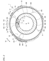
- FIG. 2 is a cross-sectional view of the rotary connector device in lines II-II of FIG.
- FIG. 3 is a perspective view of the stopper structure of the rotary connector device shown in FIG.
- FIG. 4 is an exploded perspective view of the rotary connector device shown in FIG.
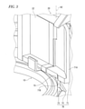
- FIG. 5 is a cross-sectional view of the stopper structure shown in FIG.
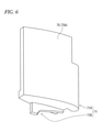
- FIG. 6 is a perspective view of a movable member having a stopper structure shown in FIG.
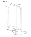
- FIG. 7 is a perspective view of a movable member having a stopper structure shown in FIG.
- FIG. 8 is a plan view of the stopper structure shown in FIG.
- FIG. 9 is a plan view of the stopper structure shown in FIG.
- FIG. 10 is an operation explanatory view of the stopper structure shown in FIG.
- FIG. 11 is an operation explanatory view of the stopper structure shown in FIG.
- the rotary connector device 1 includes a first case 10 and a second case 20.
- the first case 10 and the second case 20 are provided so as to be rotatable relative to each other around the rotation axis A1.
- the first case 10 is configured to be fixed to the vehicle body.
- the second case 20 is configured to rotate with the steering wheel. That is, the first case 10 is a stator configured to be fixed to the vehicle body.
- the second case 20 is a rotator that can rotate around the rotation axis A1 with respect to the stator. Therefore, the first case 10 may be referred to as a stator 10.
- the second case 20 may be referred to as a rotator 20.
- the first case 10 may be a rotator and the second case 20 may be a stator. That is, in the present application, the configuration provided in the stator 10 may be provided in the rotator 20, and the configuration provided in the rotator 20 may be provided in the stator 10.
- the rotary connector device 1 includes a first electric connector 30 and a second electric connector 40.
- the first electric connector 30 is attached to the first case 10.
- the first electric connector 30 projects from the first case 10 in the axial direction D1 defined along the rotation axis A1.
- the second electric connector 40 is attached to the second case 20.
- the first electric connector 30 is configured to be electrically connected to, for example, an electric device (for example, a control device and a battery) provided in the vehicle body.
- the second electric connector 40 is configured to be electrically connected to, for example, an electric circuit such as a switch of a steering wheel or an airbag device.
- the first case 10 and the second case 20 form a cable accommodating space 50 provided so as to surround the rotation axis A1.
- the cable accommodating space 50 is annular and extends in the circumferential direction D3 with respect to the rotation axis A1.
- the rotary connector device 1 includes an electric cable 60.
- the electric cable 60 is provided in the cable accommodating space 50 so as to be wound in the circumferential direction D3 defined around the rotation axis A1.
- the electric cable 60 is electrically connected to the first electric connector 30 and the second electric connector 40 (FIG. 1).
- the electric cable 60 is flexible and has a flat shape.
- the electric cable 60 may also be referred to as a flexible flat cable.
- the electric cable 60 includes a plurality of flat cables 61.
- the first case 10 includes an inner peripheral surface 10B that partially forms the cable accommodating space 50.
- the second case 20 includes an outer peripheral surface 20B provided inside the inner peripheral surface 10B in the radial direction and partially forming the cable accommodating space 50.
- the electric cable 60 includes a first winding portion 60A, a second winding portion 60B, and an intermediate portion 60C.
- the first winding portion 60A is wound along the inner peripheral surface 10B of the first case 10.
- the second winding portion 60B is wound along the outer peripheral surface 20B of the second case 20.
- the intermediate portion 60C is provided between the first winding portion 60A and the second winding portion 60B, and connects the first winding portion 60A to the second winding portion 60B.
- the first winding portion 60A is electrically connected to the first electric connector 30.
- the second winding portion 60B is electrically connected to the second electric connector 40 (FIG. 1).
- the intermediate portion 60C is bent between the first winding portion 60A and the second winding portion 60B.
- the intermediate portion 60C has, for example, a curved shape protruding in the first rotation direction D21.
- Each of the plurality of flat cables 61 includes a first winding portion 60A, a second winding portion 60B, and an intermediate portion 60C.
- the electric cable 60 is provided so that when the second case 20 rotates in the first rotation direction D21 with respect to the first case 10, the length of the second winding portion 60B of the electric cable 60 wound around the outer peripheral surface 20B decreases. It is provided in the cable accommodation space 50.
- the electric cable 60 when the second case 20 rotates in the second rotation direction D22 opposite to the first rotation direction D21 with respect to the first case 10, the second winding portion 60B of the electric cable 60 is wound around the outer peripheral surface 20B. It is provided in the cable accommodating space 50 so that the length of the cable is increased.
- the electric cable 60 has a length in which the first winding portion 60A of the electric cable 60 is wound around the inner peripheral surface 10B when the second case 20 rotates in the first rotation direction D21 with respect to the first case 10. It is provided in the cable accommodating space 50 so as to increase. In the electric cable 60, when the second case 20 rotates in the second rotation direction D22 with respect to the first case 10, the length of the first winding portion 60A of the electric cable 60 wound around the inner peripheral surface 10B decreases. , Provided in the cable accommodating space 50.
- the electric cable 60 may loosen and the state of the intermediate portion 60C of the electric cable 60 may be disrupted.
- the rotary connector device 1 includes a stopper structure 70 configured to limit the relative rotation of the first case 10 and the second case 20 to a predetermined rotation angle.
- the stopper structure 70 includes a movable member 71, a rotation limiting portion 72, and a guide portion 73.
- the movable member 71 is rotatably connected to the rotator 20 around the stopper rotation axis A2.
- the rotation limiting unit 72 is provided in the first case 10.
- the guide portion 73 is provided in the first case 10.
- the rotation limiting portion 72 is provided on the stator 10.
- the guide portion 73 is provided on the stator 10.
- the movable member 71 may be rotatably connected to the stator 10.
- the rotation limiting unit 72 may be provided on the rotator 20.
- the guide portion 73 may be provided in the rotator 20.
- the second case 20 includes the second case main body 21 and the connector support portion 22.
- the connector support portion 22 is a separate member from the second case main body 21, and is attached to the second case main body 21.
- the movable member 71 is rotatably connected to the connector support portion 22 around the stopper rotation axis A2.
- the stopper body 71A is rotatably connected to the connector support portion 22 around the stopper rotation axis A2.
- the stopper structure 70 includes a pivot pin 74.
- the pivot pin 74 connects the movable member 71 to the second case 20 so as to be rotatable around the stopper rotation axis A2.
- the connector support 22 may be integrally provided with the second case body 21 as a single (one-piece) member.
- the pivot pin 74 may be provided integrally with one of the second case 20 and the movable member 71 as a single member.
- the movable member 71 includes a stopper main body 71A and a protruding portion 71B.
- the stopper body 71A is rotatably connected to the second case 20 around the stopper rotation axis A2.
- the protruding portion 71B protrudes from the stopper main body 71A in the axial direction D1 defined along the rotation axis A1.
- the stopper rotation axis A2 is arranged parallel to the rotation axis A1. However, the stopper rotation axis A2 may be arranged non-parallel to the rotation axis A1.
- the movable member 71 is movable in the radial direction D4 orthogonal to the rotation axis A1 between the first radial position P11 and the second radial position P12 with respect to the second case 20.
- the movable member 71 can rotate about the stopper rotation axis A2 between the first radial position P11 and the second radial position P12 with respect to the second case 20.
- the second radial position P12 is arranged radially outside the first radial position P11. However, the second radial position P12 may be arranged radially inside the first radial position P11.
- the stopper body 71A includes the cable contact surface 75.
- the cable contact surface 75 can come into contact with the electric cable 60 so as to receive a radial force from the electric cable 60 depending on the state of the electric cable 60 (see, for example, FIG. 2).
- the cable contact surface 75 includes a first cable contact surface 75A and a second cable contact surface 75B.
- the second cable contact surface 75B is arranged on the back side of the first cable contact surface 75A.
- the second cable contact surface 75B is arranged radially inside the first cable contact surface 75A.
- the first cable contact surface 75A is configured to face radially outward with the movable member 71 at the first radial position P11.
- the second cable contact surface 75B is configured to face radially inward with the movable member 71 at the first radial position P11.
- the first cable contact surface 75A can come into contact with the electric cable 60 so as to receive a urging force radially inward from the electric cable 60.
- the second cable contact surface 75B can come into contact with the electric cable 60 so as to receive an urging force radially outward from the electric cable 60.
- the protrusion 71B is provided radially inside the cable contact surface 75 when viewed along the rotation axis A1.
- the protrusion 71B is provided radially inside the first cable contact surface 75A when viewed along the rotation axis A1.
- the protrusion 71B is provided radially inside the second cable contact surface 75B when viewed along the rotation axis A1.
- the protrusion 71B may be provided at the same radial position as the cable contact surface 75 when viewed along the rotation axis A1, or may be provided radially outside the cable contact surface 75.
- the rotation limiting portion 72 is circumferential with the movable member 71 so as to limit the relative rotation of the first case 10 and the second case 20 while the movable member 71 is in the second radial position P12. It is possible to contact D3.
- the protruding portion 71B can come into contact with the rotation limiting portion 72 in the circumferential direction D3.
- the rotation limiting portion 72 includes a stopper surface 72A that can come into contact with the movable member 71 in the circumferential direction D3.
- the stopper surface 72A is arranged so as to face the circumferential direction D3.
- the stopper surface 72A is arranged so as to face the second rotation direction D22.
- the protruding portion 71B can come into contact with the rotation limiting portion 72 and the circumferential direction D3.
- the radial position of the protruding portion 71B is substantially the same as the radial position of the rotation limiting portion 72.
- the protruding portion 71B is arranged at a position radially separated from the rotation limiting portion 72 with the movable member 71 at the first radial position P11. With the movable member 71 at the first radial position P11, the radial position of the protruding portion 71B is different from the radial position of the rotation limiting portion 72. In the present embodiment, with the movable member 71 at the first radial position P11, the protruding portion 71B is arranged radially inside the rotation limiting portion 72. However, with the movable member 71 at the first radial position P11, the protruding portion 71B may be arranged radially outside the rotation limiting portion 72.
- the first case 10 includes an annular groove 15.
- the protrusion 71B is arranged in the annular groove 15 with the movable member 71 at the first radial position P11. Therefore, with the movable member 71 in the first radial position P11, the second case 20 can rotate in the first rotation direction D21 and the second rotation direction D22 with respect to the first case 10.
- the protruding portion 71B of the movable member 71 becomes the stopper surface of the rotation limiting portion 72.
- the rotation of the second case 20 with respect to the first case 10 in the first rotation direction D21 is stopped.
- the stopper surface 72A faces the second rotation direction D22, the second case 20 rotates in the second rotation direction D22 with respect to the first case 10 in a state where the movable member 71 is urged outward in the radial direction.
- the rotation of the second case 20 with respect to the first case 10 in the second rotation direction D22 is not limited.
- the guide portion 73 is in contact with the movable member 71 so as to guide the movable member 71 toward the first radial position P11.
- the guide portion 73 sets the movable member 71 at the first radial position P11. It can come into contact with the movable member 71 so as to guide the direction. With the movable member 71 between the first radial position P11 and the intermediate position P13, the guide portion 73 can contact the movable member 71 so as to guide the movable member 71 toward the first radial position P11. Is.
- the rotation limiting portion 72 is arranged outside the guide portion 73 in the radial direction.
- the guide portion 73 projects from the stopper surface 72A in the circumferential direction D3.
- the guide portion 73 includes a guide surface 73A that is inclined with respect to the circumferential direction D3 when viewed along the rotation axis A1.
- the guide surface 73A is arranged so as to face inward in the radial direction.
- the guide portion 73 does not have to protrude from the stopper surface 72A in the circumferential direction D3.
- the guide surface 73A may be configured to extend radially inward from the stopper surface 72A.
- the guide surface 73A is a flat surface, but may be a curved surface.
- the guide portion 73 is configured to restrict the movable member 71 from moving toward the first radial position P11 while the movable member 71 is in the second radial position P12.
- the stopper structure 70 includes a stopper groove 72B defined by a rotation limiting portion 72 and a guide portion 73.
- the movable member 71 is inserted into the stopper groove 72B at least partially in a state where the movable member 71 is in contact with the rotation limiting portion 72.
- the protrusion 71B is partially inserted into the stopper groove 72B in a state where the protrusion 71B is in contact with the rotation limiting portion 72. If the guide portion 73 does not project from the stopper surface 72A in the circumferential direction D3, the stopper groove 72B may be omitted.
- the guide unit 73 includes the restriction surface 73B.
- the limiting surface 73B is arranged so as to face outward in the radial direction.
- the limiting surface 73B is provided on the back side of the guide surface 73A.
- the limiting surface 73B extends from the stopper surface 72A in the circumferential direction D3.
- the rotation limiting portion 72 includes an introduction surface 72C configured to introduce the protrusion 71B into the stopper surface 72A.
- the introduction surface 72C extends from the stopper surface 72A in the circumferential direction D3.
- the limiting surface 73B extends from the introduction surface 72C in the circumferential direction D3 and is arranged at a radial distance from the introduction surface 72C.
- the stopper groove 72B is formed by the stopper surface 72A, the introduction surface 72C, and the limiting surface 73B.
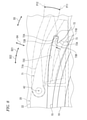
- FIG. 10 shows a state in which the second case 20 is in the neutral position P20 with respect to the first case 10.
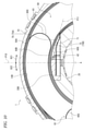
- FIG. 11 shows a state in which the second case 20 is rotated 360 degrees from the neutral position P20 to the first rotation direction D21 with respect to the first case 10.
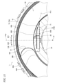
- FIG. 12 shows a state in which the second case 20 is rotated 720 degrees from the neutral position P20 to the first rotation direction D21 with respect to the first case 10.
- the electric cable 60 is composed of four flat cables 61, but FIGS. 10 to 12 simplify the electric cable 60.
- the second winding portion 60B of the electric cable 60 is wound around the outer peripheral surface 20B by about 2 to 3 turns. Therefore, the movable member 71 is urged inward in the radial direction by the electric cable 60. On the other hand, the movable member 71 is urged outward in the radial direction by the lead-out portion 60D of the electric cable 60, but the number of the second winding portions 60B arranged on the radial outer side of the movable member 71 is larger than the diameter of the movable member 71. It is larger than the number of out-licensing units 60D arranged inside the direction. Therefore, in a state where the second case 20 is in the neutral position P20 with respect to the first case 10, the movable member 71 is held at the first radial position P11 by the urging force of the electric cable 60.
- the movable member 71 can move to the first radial position P11 and the second radial position P12 according to the state of the electric cable 60.
- the urging force of the electric cable 60 for urging the movable member 71 toward the first radial position P11 becomes smaller.
- the urging force of the electric cable 60 to urge the movable member 71 toward the first radial position P11 becomes large.
- the second winding portion 60B of the electric cable 60 is wound around the outer peripheral surface 20B. Is reduced.
- the length of the second winding portion 60B wound around the outer peripheral surface 20B is reduced by the amount of the first electric cable 60. The length of the winding portion 60A wound around the inner peripheral surface 10B increases.
- the second case 20 when the second case 20 is rotated 360 degrees from the neutral position P20 to the first rotation direction D21 with respect to the first case 10, the second case 20 is wound around the outer peripheral surface 20B as compared with the neutral position P20.
- the number of 2 winding portions 60B is reduced.
- the urging force of the electric cable 60 inward in the radial direction weakens, and the movable member 71 unintentionally moves due to the minute movement of the movable member 71 with respect to the second case 20 due to individual differences in products, dimensional errors, and the like.
- the outer peripheral surface 20B is compared with the case where the second case 20 is rotated 360 degrees from the neutral position P20.
- the number of second winding portions 60B wound around is further reduced.
- the second case 20 rotates 720 degrees from the neutral position P20 to the first rotation direction D21 with respect to the first case 10
- the number of the second winding portions 60B wound around the outer peripheral surface 20B becomes zero.
- the movable member 71 is urged outward in the radial direction by the lead-out portion 60D of the electric cable 60.
- the movable member 71 when the movable member 71 is urged outward in the radial direction by the lead-out portion 60D of the electric cable 60 and the second case 20 is further rotated with respect to the first case 10, the movable member 71 is movable.
- the protruding portion 71B of the member 71 comes into contact with the stopper surface 72A of the rotation limiting portion 72, and the rotation of the second case 20 with respect to the first case 10 in the first rotation direction D21 is stopped.
- the rotation angle of the second case 20 with respect to the first case 10 in the first rotation direction D21 is limited to approximately 720 degrees by the stopper structure 70.
- the rotary connector device 1 includes a first case 10, a second case 20, an electric cable 60, and a stopper structure 70.
- the first case 10 and the second case 20 are provided so as to be relatively rotatable around the rotation axis A1 and form a cable accommodating space 50 provided so as to surround the rotation axis A1.
- the electric cable 60 is provided in the cable accommodating space 50 so as to be wound in the circumferential direction D3 defined around the rotation axis A1.
- the stopper structure 70 is configured to limit the relative rotation of the first case 10 and the second case 20 to a predetermined rotation angle.
- the stopper structure 70 includes a movable member 71, a rotation limiting portion 72, and a guide portion 73.
- the movable member 71 is movable in the radial direction orthogonal to the rotation axis A1 between the first radial position P11 and the second radial position P12 with respect to the second case 20.
- the rotation limiting portion 72 is provided in the first case 10, and is peripheral to the movable member 71 so as to limit the relative rotation of the first case 10 and the second case 20 in a state where the movable member 71 is in the second radial position P12. It is possible to contact the direction D3.
- the guide portion 73 is provided in the first case 10 and can come into contact with the movable member 71 so as to guide the movable member 71 toward the first radial position P11.
- the guide portion 73 causes the movable member 71 to move to the first radial position P11. Will be guided to. Therefore, due to the minute movement of the movable member 71 with respect to the second case 20 due to individual differences in products, dimensional errors, etc., the movable member 71 comes into contact with the rotation limiting portion 72 in an unintended state, and the first case 10 and the second case 10 and the second case 20 are brought into contact with each other. It is possible to suppress the limitation of the relative rotation of the case 20.
- the rotation limiting portion 72 is arranged outside the guide portion 73 in the radial direction. As a result, a larger rotational force can be received by the rotation limiting portion 72, and the strength of the stopper structure 70 can be increased.
- the rotation limiting portion 72 includes the movable member 71 and the stopper surface 72A that can come into contact with the circumferential direction D3.
- the guide portion 73 projects from the stopper surface 72A in the circumferential direction D3. Therefore, the guide portion 73 can reliably guide the movable member 71 toward the first radial position P11.
- the guide portion 73 includes a guide surface 73A that is inclined with respect to the circumferential direction D3 when viewed along the rotation axis A1. Therefore, the guide surface 73A can more reliably guide the movable member 71 toward the first radial position P11.
- the guide portion 73 is configured to restrict the movable member 71 from moving toward the first radial position P11 while the movable member 71 is in the second radial position P12. Therefore, for example, the contact state between the movable member 71 and the rotation limiting portion 72 can be stabilized in a state where the movable member 71 is in contact with the rotation limiting portion 72 at the second radial position P12.
- the stopper structure 70 includes a stopper groove 72B into which the movable member 71 is inserted at least partially while the movable member 71 is in contact with the rotation limiting portion 72. Therefore, for example, in a state where the movable member 71 is in contact with the rotation limiting portion 72 at the second radial position P12, the contact state between the movable member 71 and the rotation limiting portion 72 can be further stabilized.
- the movable member 71 projects from the stopper body 71A rotatably connected to the second case 20 around the stopper rotation axis A2 and the stopper body 71A in the axial direction D1 defined along the rotation axis A1 to limit rotation.
- the portion 72 includes a protruding portion 71B that can come into contact with the circumferential direction D3.
- the stopper main body 71A includes a cable contact surface 75 that can come into contact with the electric cable 60 so as to receive a radial force from the electric cable 60 according to the state of the electric cable 60.
- the movable member 71 can be moved in the radial direction by using the electric cable 60, and the structure can be simplified.
- the protrusion 71B is provided radially inside the cable contact surface 75 when viewed along the rotation axis A1. As a result, the protrusion 71B can be arranged outside the cable accommodating space 50. (10) The protruding portion 71B is arranged at a position radially separated from the rotation limiting portion 72 with the movable member 71 at the first radial position P11. Therefore, it is possible to reliably prevent the movable member 71 from unintentionally coming into contact with the rotation limiting portion 72. (11) The movable member 71 can move to the first radial position P11 and the second radial position P12 according to the state of the electric cable 60.
- the first case 10 includes an inner peripheral surface that partially forms the cable accommodating space 50.
- the second case 20 includes an outer peripheral surface provided on the radial inner side of the inner peripheral surface and partially forming the cable accommodating space 50.
- the electric cable 60 includes a first winding portion wound along the inner peripheral surface of the first case 10, a second winding portion wound along the outer peripheral surface of the second case 20, and a first winding portion and a second winding portion. It includes an intermediate portion provided between the portions and connecting the first winding portion to the second winding portion.
- the electric cable 60 accommodates the cable so that when the second case 20 rotates in the first rotation direction D21 with respect to the first case 10, the length of the second winding portion of the electric cable 60 wound around the outer peripheral surface decreases. It is provided in the space 50.
- the electric cable 60 when the second case 20 rotates in the second rotation direction D22 opposite to the first rotation direction D21 with respect to the first case 10, the second winding portion of the electric cable 60 is wound around the outer peripheral surface. It is provided in the cable accommodating space 50 so as to increase the length.
- the urging force of the electric cable 60 for urging the movable member 71 toward the first radial position P11 becomes smaller.
- the first case 10 is a stator configured to be fixed to the vehicle body.
- the second case 20 is a rotator that can rotate around the rotation axis A1 with respect to the stator 10.
- the movable member 71 is rotatably connected to the rotator around the stopper rotation axis A2.
- the rotation limiting portion 72 is provided on the stator 10. Therefore, the rotation limiting portion 72 provided on the stator 10 can receive a larger force and increase the strength of the stopper structure 70.
- ordinal numbers such as “first” and “second” are merely terms for identifying the composition and have no other meaning (for example, a specific order). For example, the existence of the “first element” does not imply that the “second element” exists, and the existence of the “second element” does not imply the existence of the “first element”. It does not imply that the "element” exists.
- the expression "at least one of A and B” in the present disclosure includes, for example, any of (1) A only, (2) B only, and (3) both A and B. ..
- the expression "at least one of A, B and C” is, for example, (1) A only, (2) B only, (3) C only, (4) A and B, (5) B and C, All of (6) A and C and (7) A, B and C are included.
- the expression "at least one of A and B" is not construed as "at least one of A and at least one of B".
- Rotating connector device 10 First case, stator 10B: Inner peripheral surface 15: Circular groove 20: Second case, rotator 20B: Outer peripheral surface 30: First electric connector 40: Second electric connector 50: Cable accommodation space 60: Electric cable 60A: First winding part 60B: Second winding part 60C: Intermediate part 60D: Leading part 70: Stopper structure 71 : Movable member 71A: Stopper body 71B: Protruding part 72: Rotation limiting part 72A: Stopper surface 72B: Stopper groove 72C: Introducing surface 73: Guide part 73A: Guide surface 73B: Limiting surface 75: Cable contact surface 75A: First cable Contact surface 75B: Second cable contact surface A1: Rotation axis A2: Stopper rotation axis D1: Axial direction D21: First rotation direction D22: Second rotation direction D3: Circumferential direction D4: Radial direction P11: First radial position P12 : 2nd radial position P13: Intermediate position
Landscapes
- Engineering & Computer Science (AREA)
- Mechanical Engineering (AREA)
- Electric Cable Arrangement Between Relatively Moving Parts (AREA)
- Chemical & Material Sciences (AREA)
- Combustion & Propulsion (AREA)
- Transportation (AREA)
- Details Of Connecting Devices For Male And Female Coupling (AREA)
- Steering Controls (AREA)
Priority Applications (5)
| Application Number | Priority Date | Filing Date | Title |
|---|---|---|---|
| JP2022536248A JPWO2022014349A1 (zh) | 2020-07-13 | 2021-07-01 | |
| KR1020237004596A KR20230029998A (ko) | 2020-07-13 | 2021-07-01 | 회전 커넥터 장치 |
| CN202180047328.7A CN115917891A (zh) | 2020-07-13 | 2021-07-01 | 旋转连接器装置 |
| EP21841656.8A EP4178049A4 (en) | 2020-07-13 | 2021-07-01 | ROTARY CONNECTOR DEVICE |
| US18/096,496 US20230170656A1 (en) | 2020-07-13 | 2023-01-12 | Rotary connector device |
Applications Claiming Priority (2)
| Application Number | Priority Date | Filing Date | Title |
|---|---|---|---|
| JP2020-120064 | 2020-07-13 | ||
| JP2020120064 | 2020-07-13 |
Related Child Applications (1)
| Application Number | Title | Priority Date | Filing Date |
|---|---|---|---|
| US18/096,496 Continuation US20230170656A1 (en) | 2020-07-13 | 2023-01-12 | Rotary connector device |
Publications (1)
| Publication Number | Publication Date |
|---|---|
| WO2022014349A1 true WO2022014349A1 (ja) | 2022-01-20 |
Family
ID=79554751
Family Applications (1)
| Application Number | Title | Priority Date | Filing Date |
|---|---|---|---|
| PCT/JP2021/025012 WO2022014349A1 (ja) | 2020-07-13 | 2021-07-01 | 回転コネクタ装置 |
Country Status (6)
| Country | Link |
|---|---|
| US (1) | US20230170656A1 (zh) |
| EP (1) | EP4178049A4 (zh) |
| JP (1) | JPWO2022014349A1 (zh) |
| KR (1) | KR20230029998A (zh) |
| CN (1) | CN115917891A (zh) |
| WO (1) | WO2022014349A1 (zh) |
Cited By (1)
| Publication number | Priority date | Publication date | Assignee | Title |
|---|---|---|---|---|
| WO2024012466A1 (zh) * | 2022-07-12 | 2024-01-18 | 杭州巨星科技股份有限公司 | 一种疏通器 |
Citations (3)
| Publication number | Priority date | Publication date | Assignee | Title |
|---|---|---|---|---|
| JPH02139875U (zh) * | 1989-04-26 | 1990-11-22 | ||
| JP2002218639A (ja) | 2001-01-15 | 2002-08-02 | Furukawa Electric Co Ltd:The | 回転コネクタ |
| WO2014157233A1 (ja) * | 2013-03-27 | 2014-10-02 | アルプス電気株式会社 | 回転コネクタ |
Family Cites Families (1)
| Publication number | Priority date | Publication date | Assignee | Title |
|---|---|---|---|---|
| JP2540938Y2 (ja) * | 1992-09-04 | 1997-07-09 | 古河電気工業株式会社 | 回転体と固定体間の伝送装置 |
-
2021
- 2021-07-01 CN CN202180047328.7A patent/CN115917891A/zh active Pending
- 2021-07-01 JP JP2022536248A patent/JPWO2022014349A1/ja active Pending
- 2021-07-01 WO PCT/JP2021/025012 patent/WO2022014349A1/ja unknown
- 2021-07-01 KR KR1020237004596A patent/KR20230029998A/ko unknown
- 2021-07-01 EP EP21841656.8A patent/EP4178049A4/en active Pending
-
2023
- 2023-01-12 US US18/096,496 patent/US20230170656A1/en active Pending
Patent Citations (3)
| Publication number | Priority date | Publication date | Assignee | Title |
|---|---|---|---|---|
| JPH02139875U (zh) * | 1989-04-26 | 1990-11-22 | ||
| JP2002218639A (ja) | 2001-01-15 | 2002-08-02 | Furukawa Electric Co Ltd:The | 回転コネクタ |
| WO2014157233A1 (ja) * | 2013-03-27 | 2014-10-02 | アルプス電気株式会社 | 回転コネクタ |
Non-Patent Citations (1)
| Title |
|---|
| See also references of EP4178049A4 |
Cited By (1)
| Publication number | Priority date | Publication date | Assignee | Title |
|---|---|---|---|---|
| WO2024012466A1 (zh) * | 2022-07-12 | 2024-01-18 | 杭州巨星科技股份有限公司 | 一种疏通器 |
Also Published As
| Publication number | Publication date |
|---|---|
| KR20230029998A (ko) | 2023-03-03 |
| CN115917891A (zh) | 2023-04-04 |
| US20230170656A1 (en) | 2023-06-01 |
| EP4178049A4 (en) | 2023-12-20 |
| EP4178049A1 (en) | 2023-05-10 |
| JPWO2022014349A1 (zh) | 2022-01-20 |
Similar Documents
| Publication | Publication Date | Title |
|---|---|---|
| EP1094570B1 (en) | Rotating connector | |
| EP2597734B1 (en) | Rotary connector device | |
| EP2555345B1 (en) | Rotary connector device | |
| JP5871438B2 (ja) | 回転コネクタ | |
| WO2022014349A1 (ja) | 回転コネクタ装置 | |
| JP6442173B2 (ja) | 回転コネクタ | |
| WO2011122469A1 (ja) | 回転コネクタ装置 | |
| EP2555346B1 (en) | Rotary connector device | |
| JP5624972B2 (ja) | 回転コネクタ装置 | |
| KR20210017262A (ko) | 유니버셜 조인트 어셈블리 | |
| CN111033668B (zh) | 限位开关 | |
| JP2000021533A (ja) | 回転コネクタ | |
| JPH08180950A (ja) | ハンドルとステアリングコラム間の電気的接続装置 | |
| CN111033667B (zh) | 限位开关 | |
| EP1806812B1 (en) | Rotary connector | |
| US20230170657A1 (en) | Rotary connector device | |
| JP2022170317A (ja) | 回転コネクタ装置 | |
| CN111066111B (zh) | 限位开关 | |
| US20220402425A1 (en) | Cancel cam | |
| EP3093863B1 (en) | Rotation transmitting mechanism and lever switch adopting rotation transmitting mechanism | |
| KR20210083530A (ko) | 자동차의 조향장치 | |
| CN115892184A (zh) | 方向盘的继电构造 | |
| JPH0756285Y2 (ja) | ケーブルリール | |
| JP2023065197A (ja) | 回転コネクタ装置 | |
| JP2022185404A (ja) | 回転コネクタ装置およびステアリング装置 |
Legal Events
| Date | Code | Title | Description |
|---|---|---|---|
| 121 | Ep: the epo has been informed by wipo that ep was designated in this application |
Ref document number: 21841656 Country of ref document: EP Kind code of ref document: A1 |
|
| ENP | Entry into the national phase |
Ref document number: 2022536248 Country of ref document: JP Kind code of ref document: A |
|
| ENP | Entry into the national phase |
Ref document number: 2021841656 Country of ref document: EP Effective date: 20230201 |
|
| NENP | Non-entry into the national phase |
Ref country code: DE |