WO2022014254A1 - 振れ補正機能付き光学ユニットおよびフレキシブルプリント基板の折り曲げ方法 - Google Patents
振れ補正機能付き光学ユニットおよびフレキシブルプリント基板の折り曲げ方法 Download PDFInfo
- Publication number
- WO2022014254A1 WO2022014254A1 PCT/JP2021/023130 JP2021023130W WO2022014254A1 WO 2022014254 A1 WO2022014254 A1 WO 2022014254A1 JP 2021023130 W JP2021023130 W JP 2021023130W WO 2022014254 A1 WO2022014254 A1 WO 2022014254A1
- Authority
- WO
- WIPO (PCT)
- Prior art keywords
- flexible printed
- axis
- bent
- movable body
- axis direction
- Prior art date
- Legal status (The legal status is an assumption and is not a legal conclusion. Google has not performed a legal analysis and makes no representation as to the accuracy of the status listed.)
- Ceased
Links
Images






Classifications
-
- G—PHYSICS
- G03—PHOTOGRAPHY; CINEMATOGRAPHY; ANALOGOUS TECHNIQUES USING WAVES OTHER THAN OPTICAL WAVES; ELECTROGRAPHY; HOLOGRAPHY
- G03B—APPARATUS OR ARRANGEMENTS FOR TAKING PHOTOGRAPHS OR FOR PROJECTING OR VIEWING THEM; APPARATUS OR ARRANGEMENTS EMPLOYING ANALOGOUS TECHNIQUES USING WAVES OTHER THAN OPTICAL WAVES; ACCESSORIES THEREFOR
- G03B15/00—Special procedures for taking photographs; Apparatus therefor
-
- G—PHYSICS
- G03—PHOTOGRAPHY; CINEMATOGRAPHY; ANALOGOUS TECHNIQUES USING WAVES OTHER THAN OPTICAL WAVES; ELECTROGRAPHY; HOLOGRAPHY
- G03B—APPARATUS OR ARRANGEMENTS FOR TAKING PHOTOGRAPHS OR FOR PROJECTING OR VIEWING THEM; APPARATUS OR ARRANGEMENTS EMPLOYING ANALOGOUS TECHNIQUES USING WAVES OTHER THAN OPTICAL WAVES; ACCESSORIES THEREFOR
- G03B17/00—Details of cameras or camera bodies; Accessories therefor
- G03B17/02—Bodies
-
- G—PHYSICS
- G03—PHOTOGRAPHY; CINEMATOGRAPHY; ANALOGOUS TECHNIQUES USING WAVES OTHER THAN OPTICAL WAVES; ELECTROGRAPHY; HOLOGRAPHY
- G03B—APPARATUS OR ARRANGEMENTS FOR TAKING PHOTOGRAPHS OR FOR PROJECTING OR VIEWING THEM; APPARATUS OR ARRANGEMENTS EMPLOYING ANALOGOUS TECHNIQUES USING WAVES OTHER THAN OPTICAL WAVES; ACCESSORIES THEREFOR
- G03B30/00—Camera modules comprising integrated lens units and imaging units, specially adapted for being embedded in other devices, e.g. mobile phones or vehicles
-
- G—PHYSICS
- G03—PHOTOGRAPHY; CINEMATOGRAPHY; ANALOGOUS TECHNIQUES USING WAVES OTHER THAN OPTICAL WAVES; ELECTROGRAPHY; HOLOGRAPHY
- G03B—APPARATUS OR ARRANGEMENTS FOR TAKING PHOTOGRAPHS OR FOR PROJECTING OR VIEWING THEM; APPARATUS OR ARRANGEMENTS EMPLOYING ANALOGOUS TECHNIQUES USING WAVES OTHER THAN OPTICAL WAVES; ACCESSORIES THEREFOR
- G03B5/00—Adjustment of optical system relative to image or object surface other than for focusing
-
- H—ELECTRICITY
- H05—ELECTRIC TECHNIQUES NOT OTHERWISE PROVIDED FOR
- H05K—PRINTED CIRCUITS; CASINGS OR CONSTRUCTIONAL DETAILS OF ELECTRIC APPARATUS; MANUFACTURE OF ASSEMBLAGES OF ELECTRICAL COMPONENTS
- H05K1/00—Printed circuits
- H05K1/02—Details
Definitions
- the present invention relates to an optical unit with a shake correction function that swings an optical module to correct runout, and a method of bending a flexible printed circuit board connected to the optical module.
- Patent Document 1 discloses this kind of optical unit with a shake correction function.
- the optical unit with a runout correction function of Patent Document 1 can rotate around a movable body including an optical module, a fixed body, and a rotation axis (X-axis, Y-axis) at which the movable body intersects the optical axis with respect to the fixed body. It has a swing support mechanism that supports it, and swings the movable body in the pitching direction and the yawing direction. A flexible printed circuit board (flexible wiring board) connected to the optical module is pulled out from the movable body.
- the movable body swings while bending the flexible printed circuit board. At this time, the springiness of the flexible printed substrate may hinder the movement of the movable body and increase the load for swinging the movable body.
- Patent Document 1 in order to make the flexible printed substrate more flexible, it is folded back so as to overlap when viewed from the optical axis direction.
- the flexible printed substrate is processed into a shape having a small spring constant by folding it in multiple directions to make it easy to bend.
- the assemblability of the flexible printed circuit board is reduced.
- an object of the present invention is to suppress a decrease in assembling property and a decrease in shape accuracy of a flexible printed circuit board connected to a movable body.
- the movable body provided with the optical module, the fixed body, and the three axes orthogonal to each other are defined as X-axis, Y-axis, and Z-axis, and the optical unit is described.
- the direction along the optical axis of the module is the Z axis
- the movable body can swing around the X axis and the movable body can swing around the Y axis with respect to the fixed body.
- a swing support mechanism that supports the movable body so as to swing around the Z axis with respect to the fixed body, and a swing support mechanism that swings the movable body around the X axis and the Y axis.
- the flexible printed board has the movable body.
- the bent portion is provided with one or a plurality of bent portions to be formed, and the bent portion includes a first inclined portion extending in a direction toward one side in the Z-axis direction toward one side in the X-axis direction and a first folding portion.
- a second inclined portion connected to the first inclined portion via a portion and extending in a direction toward the other side in the Z-axis direction as it goes toward one side in the X-axis direction, and includes the first inclined portion.
- the second inclined portion is characterized in that it has a shape folded back in the Y-axis direction via the first folded portion when viewed from the Z-axis direction.
- a flexible printed substrate drawn from a movable body in a direction intersecting the optical axis (Z-axis direction) (X-axis direction) is arranged between a fixed portion fixed to the fixed body and the movable body.
- the bent portion is provided with a bent portion to be bent, and the bent portion has a shape extending in a direction inclined with respect to the Z-axis direction and the X-axis direction and folded back, and also has a shape folded back in the Y-axis direction when viewed from the Z-axis direction. It has become.
- the flexible printed substrate easily bends when the movable body swings around three axes, so that an increase in the swing load of the movable body can be suppressed.
- the first inclined portion and the second inclined portion constituting the bent portion extend in the inclined direction in any of the X-axis, Y-axis, and Z-axis directions. While making it smaller, the lengths of the first inclined portion and the second inclined portion can be increased. Therefore, since the spring constant can be reduced, the swing load of the movable body can be reduced.
- the labor required for the bending work can be reduced and the deterioration of the assembling property can be suppressed as compared with the case of bending in multiple directions.
- the bent portion provided with the plurality of bent portions arranged in the X-axis direction and closest to the movable body has a smaller height in the Z-axis direction than the other bent portions.
- the spring constant of the flexible printed circuit board can be reduced, and the flexible printed circuit board can be easily bent. Therefore, it is possible to suppress an increase in the swing load of the movable body.
- the second folded portion for connecting the bent portions adjacent to each other in the X-axis direction is provided, and the positions of the second folded portion and the first folded portion are different in the Y-axis direction.
- the present invention it is preferable to provide a bending assist member attached to the first folded portion and the second folded portion. By doing so, it is easy to maintain the shape of the folded portion. Therefore, when the movable body is returned to the origin position, the flexible printed substrate easily returns to the original shape, so that the flexible printed substrate can be maintained in a flexible state.
- the flexible printed substrate includes a first surface and a second surface facing the back side of the first surface, and all the bending assist members are attached to one of the first surface and the second surface. It is preferable that it is. In this way, the work of attaching the bending auxiliary member to the flexible printed substrate is easy.
- the flexible printed circuit board includes a first surface and a second surface facing the back side of the first surface, and in the first folded portion, the first surface has a mountain-folded shape.
- the flexible printed circuit board is bent, and the bending auxiliary member is attached to the first surface.
- the flexible printed circuit board has a mountain-folded shape so that the second surface has a mountain-folded shape.
- the bending assisting member is bent and the bending assisting member is attached to the second surface. In this way, the folded portion can be held by the bending assist member from the outer peripheral side in both the first folded portion and the second folded portion.
- the bending auxiliary member is bent together with the flexible printed substrate, it can be deformed by pressing from the side of the bending auxiliary member. Therefore, there is little possibility that the wiring in the flexible printed board will be broken.
- the bending assist member includes a first fixing portion fixed to the first inclined portion, a second fixing portion fixed to the second inclined portion, the first fixing portion and the second fixing portion.
- the first fixing portion and the second fixing portion extend in the width direction of the flexible printed substrate, and the bending portion includes the first fixing portion and the first fixing portion. 2
- the bent portion includes a first bent portion connecting the first fixed portion and one end of the second fixed portion in the width direction, and the first fixed portion and the second fixed portion in the width direction. It is also possible to adopt a configuration including a second bent portion for connecting the ends. By doing so, it is possible to reduce the area where stress is applied to the flexible printed substrate when the bending auxiliary member is bent together with the flexible printed substrate. Therefore, it is possible to reduce the possibility that the wiring in the flexible printed substrate will be broken when the bent portion is bent.
- the fixed portion is connected to one of the first inclined portion and the second inclined portion, and the fixed portion is in the same direction as one of the first inclined portion and the second inclined portion. It is preferably extended. In this way, the fixed portion and the first inclined portion or the second inclined portion can be connected in a straight line. Therefore, since it is not necessary to bend the flexible printed circuit board between the fixed portion and the flexible portion, the number of times the flexible printed circuit board is bent can be reduced. Therefore, it is possible to suppress a decrease in the shape accuracy of the flexible printed circuit board.
- the two flexible printed boards arranged in the Y-axis direction are provided, and the two flexible printed boards are symmetrical with respect to a virtual plane that passes through the swing center of the movable body and is parallel to the XZ plane. It is preferable that it is configured in. Since the flexible printed substrate can be made thinner by dividing it into two, the height and width of the bent portion can be reduced. Therefore, the outer shape of the bent portion can be reduced, and the height of the optical unit with the shake correction function in the optical axis direction (Z-axis direction) can be reduced. Further, since the spring constant is smaller and the flexible printed substrate is more easily bent than when one thick flexible printed substrate is used, the load when the movable body swings can be reduced. Further, by forming the shape symmetrical with respect to the virtual surface passing through the swing center of the movable body, it is possible to deform the movable body in a well-balanced manner when the movable body swings.
- the present invention is a method for bending a flexible printed circuit board included in the optical unit with a runout correction function, wherein the flexible printed circuit board having a shape folded back in a plane has a shape that matches the bent shape of the bent portion.
- the flexible printed circuit board is bent into the shape of the bent portion by setting the flexible printed circuit board on the die provided with the receiving surface and pressing the flexible printed circuit board against the receiving surface by a punch provided with a pressing surface having an inverted shape of the receiving surface. It is a feature.
- the folding method of the present invention since it is only necessary to set the flexible printed substrate on the die and press it against the die with a punch, it can be bent more easily and with high shape accuracy than manually bending. Therefore, the labor required for the bending work can be reduced, and the deterioration of the assembling property can be suppressed. In addition, it is possible to suppress a decrease in shape accuracy of the flexible printed circuit board.
- a flexible printed substrate drawn from a movable body in a direction intersecting the optical axis (Z-axis direction) (X-axis direction) is arranged between a fixed portion fixed to the fixed body and the movable body.
- the bent portion is provided with a bent portion to be bent, and the bent portion has a shape extending in a direction inclined with respect to the Z-axis direction and the X-axis direction and folded back, and also has a shape folded back in the Y-axis direction when viewed from the Z-axis direction. It has become.
- the flexible printed substrate easily bends when the movable body swings around three axes, so that an increase in the swing load of the movable body can be suppressed.
- the first inclined portion and the second inclined portion constituting the bent portion extend in the inclined direction in any of the X-axis, Y-axis, and Z-axis directions. While making it smaller, the lengths of the first inclined portion and the second inclined portion can be increased. Therefore, since the spring constant can be reduced, the swing load of the movable body can be reduced.
- the labor required for the bending work can be reduced and the deterioration of the assembling property can be suppressed as compared with the case of bending in multiple directions.
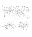
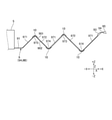
- FIG. 1 is a plan view of the optical unit 1 with a shake correction function to which the present invention is applied
- FIG. 2 is a side view of the optical unit 1 with a shake correction function to which the present invention is applied.
- a part of the configuration of the optical unit 1 with the shake correction function is schematically displayed or not shown.
- the optical unit 1 with a shake correction function has an optical module 4 provided with a lens 2 and an image pickup element 3.
- the optical unit 1 with a shake correction function is used, for example, in an optical device such as a mobile phone with a camera and a drive recorder, and an optical device such as an action camera and a wearable camera mounted on a moving body such as a helmet, a bicycle, and a radiocon helicopter. .. In such an optical device, if the optical device shakes during shooting, the captured image is distorted.
- the optical unit 1 with a shake correction function corrects the tilt of the optical module 4 based on the acceleration, the angular velocity, the amount of runout, etc. detected by a detection means such as a gyroscope in order to prevent the captured image from tilting.
- the three axes orthogonal to each other will be the X-axis, Y-axis, and Z-axis.
- the Z axis coincides with the optical axis L of the optical module 4.
- the optical unit 1 with a runout correction function performs runout correction in the pitching direction and the yawing direction by swinging the optical module 4 around the X axis and the Y axis. Further, the optical unit 1 with a runout correction function performs runout correction in the rolling direction by rotating the optical module 4 around the Z axis.
- the directions along the X-axis, Y-axis, and Z-axis are defined as the X-axis direction, the Y-axis direction, and the Z-axis direction.
- One side in the X-axis direction is the -X direction
- the other side is the + X direction
- one side in the Y-axis direction is the -Y direction
- the other side is the + Y direction
- one side in the Z-axis direction is the -Z direction
- the other side is the other side.
- the Z-axis direction is the optical axis direction along the optical axis L.
- the ⁇ Z direction is the image side of the optical module 4
- the + Z direction is the subject side of the optical module 4.
- the optical unit 1 with a runout correction function includes a movable body 5 including an optical module 4, a gimbal mechanism (not shown), a rolling support mechanism (not shown), and a gimbal mechanism and a rolling mechanism.
- a fixed body 8 that supports the movable body 5 via the above, a rocking drive mechanism 6, a rolling drive mechanism 7, and a flexible printed substrate 9 are provided.
- the flexible printed substrate 9 is connected to the movable body 5.
- the movable body 5 includes an optical module 4 and a holder 5a that surrounds the optical module 4.
- the optical module 4 includes a lens barrel 4a that projects in the + Z direction from the center of the holder 5a, and the lens 2 is held by the lens barrel 4a.
- the flexible printed substrate 9 is pulled out from the end portion of the movable body 5 in the ⁇ Z direction in the + Z direction.
- the fixed body 8 includes a first case 21 that houses the movable body 5 and the flexible printed substrate 9, and a second case 20 that is fixed to the end portion of the first case 21 in the ⁇ Z direction.
- the first case 21 can also be composed of a plurality of members.
- the first case 21 may include a case for accommodating the movable body 5, a wiring case for accommodating the flexible printed substrate 9, and a cover for covering the case and the wiring case.
- the flexible printed circuit board 9 is fixed to the substrate fixing portion 22 protruding in the ⁇ Z direction from the end portion in the + X direction of the first case 21.
- the gimbal mechanism is a swing support mechanism that swingably supports the movable body 5 around the first axis R1 and around the second axis R2.
- the movable body 5 can swing around the swing center P, which is an intersection where the optical axis L, the first axis R1, and the second axis R2 intersect.
- the movable body 5 can rotate around the X axis and around the Y axis by combining the rotation around the first axis R1 and the rotation around the second axis R2. Therefore, the gimbal mechanism supports the movable body swingably around the X axis and swingably around the Y axis.
- the first axis R1 and the second axis R2 are orthogonal to, for example, the optical axis L, and are tilted by 45 degrees with respect to the X axis and the Y axis.
- the rolling support mechanism supports the movable body 5 so as to be swingable around the optical axis L (Z axis). Since the gimbal mechanism and the rolling support mechanism are known mechanisms, detailed description and illustration are omitted.
- the movable body 5 can be connected to the rolling support mechanism, and a gimbal mechanism can be configured between the rolling support mechanism and the fixed body 8.
- the swing drive mechanism 6 includes a first swing drive mechanism 6X that generates a driving force around the X axis with respect to the movable body 5, and a second swing drive mechanism 6 that generates a driving force around the Y axis with respect to the movable body 5.
- a drive mechanism 6Y is provided.
- the first rocking drive mechanism 6X, the second rocking drive mechanism 6Y, and the rolling drive mechanism 7 all have a magnet 61 arranged on the movable body 5 and a coil 62 arranged on the fixed body 8. It is a magnetic drive mechanism in which and are opposed to each other in the radial direction. The arrangement of the magnet 61 and the coil 62 may be reversed.
- the first swing drive mechanism 6X is arranged in the ⁇ Y direction of the movable body 5.
- the second swing drive mechanism 6Y is arranged in the ⁇ X direction of the movable body 5.
- the rolling drive mechanism 7 is arranged in the + Y direction of the movable body 5.
- the magnet 61 of the first swing drive mechanism 6X and the second swing drive mechanism 6Y is polarized and magnetized in the Z-axis direction.
- the magnet 61 of the rolling drive mechanism 7 is polarized and magnetized in the circumferential direction around the Z axis.
- the flexible printed substrate 9 includes two flexible printed substrates 9A and 9B extending in the X-axis direction.
- the flexible printed substrates 9A and 9B are symmetrically configured with reference to a virtual surface V that passes through the swing center P of the movable body 5 and is parallel to the XZ surface.
- the flexible printed boards 9A and 9B each include a drawer portion 91 that is pulled out from the movable body 5 in the + X direction, a flexure portion 92 that extends from the drawer portion 91 in the + X direction, and a fixed portion 93 that is connected to the flexure portion 92. ..
- the fixed portions 93 of the flexible printed substrates 9A and 9B are connected.
- the fixed body 8 includes a substrate fixing portion 22 separated from the movable body 5 in the + X direction, and the fixed portion 93 is a fixing surface 23 provided at the tip of the substrate fixing portion 22 by an adhesive. It is fixed to (see Fig. 2).
- the fixed surface 23 is inclined in the direction toward the + Z direction toward the + X direction.
- the fixed portion 93 extends in the same direction as the end portion of the flexible portion 92 in the + X direction and is fixed to the fixed surface 23.
- the flexible printed circuit board 9 includes a stretched portion 94 extending from the fixed portion 93 in the + X direction, and a wiring board 95 provided at the tip of the stretched portion 94. The stretched portion 94 and the wiring board 95 are pulled out to the outside of the fixed body 8.
- the wiring board 95 is provided with a terminal for connecting to an optical device on which the optical unit 1 with a runout correction function is mounted.
- the flexible printed substrate 9 includes a base film made of polyimide resin or the like, a conductor layer forming a wiring pattern, and a cover film.
- the flexible printed circuit board 9 may be a double-sided substrate in which wiring patterns are formed on both sides, or may be a single-sided substrate. Alternatively, it may be a multilayer board in which the wiring pattern is formed in multiple layers.
- a bending assisting member 10 for holding the flexible printed substrate 9 in a bent shape is fixed to the bending portion 92.
- a reinforcing plate 96 is fixed to the fixed portion 93.
- the bent portion 92 includes a plurality of bent portions that are folded back into a shape that protrudes in the + Z direction.
- the flexible portion 92 includes two bent portions 97A and 97B arranged in the X-axis direction. The heights of the two bent portions 97A and 97B in the Z-axis direction are different. In this embodiment, the height H1 in the Z-axis direction of the bent portion 97A closest to the movable body 5 is smaller than the height H2 in the Z-axis direction of the other bent portions 97B.
- the bent portions 97A and 97B each include a first inclined portion 971 and a second inclined portion 972 connected to the first inclined portion 971 via the first folded portion 973.
- the first inclined portion 971 extends in the direction toward the + Z direction (one side in the Z axis direction) toward the + X direction (one side in the X axis direction).
- the second inclined portion 972 extends in the direction toward the ⁇ Z direction (the other side in the Z axis direction) toward the + X direction (one side in the X axis direction).
- the first inclined portion 971 and the second inclined portion 972 are inclined by 45 ° with respect to the Z-axis direction.
- the bending angle of the bent portions 97A and 97B is 90 °.
- the height of the flexible portion 92 in the Z-axis direction is reduced by inclining the first inclined portion 971 and the second inclined portion 972 with respect to the Z-axis direction.
- the bent portions 97A and 97B are connected via the second folded portion 974.
- the second folded portion 974 connects the second inclined portion 972 of the bent portion 97A and the first inclined portion 971 of the bent portion 97B.
- the bent portion 92 is folded back in a shape protruding in the + Z direction in the first folded portion 973, and folded in a shape protruding in the ⁇ Z direction in the second folded portion 974.
- the bent portion 92 is folded back in the opposite directions at the first folded portion 973 and the second folded portion 974, and extends in the X-axis direction while meandering.
- the flexible portion 92 is provided with a first folded portion 973 and a second folded portion 974 at two locations each, and is folded back four times in the Z-axis direction.
- the second inclined portion 972 of the bent portion 97B is connected to the first inclined portion 971 arranged at the end portion of the bent portion 92 in the + X direction via the second folded portion 974.
- the fixed portion 93 is connected to a first inclined portion 971 arranged at an end portion of the bent portion 97 in the + X direction, and is inclined in the same direction as the first inclined portion 971.
- the positions of the first folded portion 973 and the second folded portion 974 in the Y-axis direction are different. Due to the misalignment of the first folded portion 973 and the second folded portion 974 in the Y-axis direction, the bent portions 97A and 97B have a shape folded in the Y-axis direction when viewed from the Z-axis direction. There is.
- the first inclined portion 971, the first folded portion 973, and the second inclined portion 972 are connected to each other in a semicircular curved shape when viewed from the Z-axis direction.
- the second inclined portion 972, the second folded portion 974, and the first inclined portion 971 are connected to each other in a semicircular curved shape when viewed from the Z-axis direction.
- the first inclined portion 971 and the second inclined portion 972 are curved, but they may be linear.
- the flexible printed boards 9A and 9B are folded back into a symmetrical shape with respect to the virtual surface V when viewed from the Z-axis direction.
- the bent portion 92 is folded back in a shape protruding in the ⁇ Y direction at the first folded portion 973, and folded back in a shape protruding in the + Y direction at the second folded portion 974.
- the first inclined portion 971 is inclined in the direction toward the ⁇ Y direction toward the + X direction.
- the second inclined portion 972 is inclined in the direction toward the + Y direction toward the + X direction.
- the bent portion 92 is folded back in a shape protruding in the + Y direction at the first folded portion 973, and is folded back in a shape protruding in the ⁇ Y direction at the second folded portion 974.
- the first inclined portion 971 is inclined in the direction toward the + Y direction toward the + X direction.
- the second inclined portion 972 is inclined in the direction toward the ⁇ Y direction toward the + X direction.
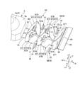
- FIG. 3 is an exploded perspective view of the flexible printed substrate 9 and the bending auxiliary member 10.
- FIG. 4 is a developed view of the flexible printed substrate 9, and is a diagram showing a state before bending.
- the bending auxiliary member 10 includes a first fixing portion 11 fixed to the first inclined portion 971, a second fixing portion 12 fixed to the second inclined portion 972, and a first fixing portion 11.
- a bending portion 13 for connecting the second fixing portion 12 and the second fixing portion 12 is provided.
- the bending auxiliary member 10 is a rectangular sheet metal member extending in the width direction (Y direction) of the flexible printed substrate 9.
- the flexible printed substrate 9 includes a first surface 901 facing in the + Z direction and a second surface 902 facing the back side ( ⁇ Z direction) of the first surface 901.
- all the bending auxiliary members 10 are fixed to the first surface 901.
- the first folded-back portion 973 is bent so that the first surface 901 has a mountain-folded shape, and the bending auxiliary member 10 is fixed to the outer peripheral side surface of the first folded-back portion 973.
- the second folded portion 974 the first surface 901 is bent so as to have a valley fold shape, and the bending auxiliary member 10 is fixed to the inner peripheral side surface of the second folded portion 974.
- the bending auxiliary member 10 is fixed to the flexible printed substrate 9 before the bending process, and the bending auxiliary member 10 is bent at the same time when the flexible printed substrate 9 is bent.
- the bending auxiliary member 10 is fixed to the flexible printed substrate 9 before bending with an adhesive or double-sided tape in a state where the bending portion 13 is not bent.
- the first fixing portion 11 and the second fixing portion 12 of each bending auxiliary member 10 are fixed to the flexible printed substrate 9.
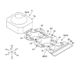
- FIG. 5 is a perspective view of a processing tool used for bending the flexible printed substrate 9 and the flexible printed substrate 9 before processing.
- the processing tool is composed of a die 110 and punches 120, 130, 140.
- the die 110 includes receiving surfaces 111, 112, 113, 114, 115 arranged so as to have the same shape as the bending shape of the bending portion 92, and also includes a recess 116 for arranging the movable body 5.
- the punch 120 includes pressing surfaces 121 and 122 having the same shape as the bending shape of the bent portion 97A.
- the punch 130 includes pressing surfaces 131 and 132 having the same shape as the bending shape of the bent portion 97B.
- the punch 140 includes a pressing surface 141 having the same inclination angle as the first inclined portion 971 arranged at the end portion of the bent portion 92 in the + X direction.
- FIG. 6 is an explanatory diagram of a bending method of the flexible printed substrate 9.
- the bending method of this embodiment is a method of pressing and bending the flexible printed substrate 9 with the die 110 and the punches 120, 130, 140.
- the movable body 5 is arranged in the recess 116 provided in the die 110, and the flexible printed substrate 9 is set in a state of being extended on the receiving surfaces 111 to 115. ..
- the punch 120 is pressed toward the receiving surfaces 111 and 112 to form the bent portion 97A.
- the punch 120 is pressed with tension applied to the flexible printed substrate 9.
- the flexible printed substrate 9 is bent so that the surface (first surface 901) on the side to which the bending auxiliary member 10 is attached has a mountain-folded shape, and the first folded portion 973 is formed. Further, the first bending auxiliary member 10 is bent on the outer peripheral side of the first folded portion 973 to form the bent portion 13.
- the punch 130 is pressed toward the receiving surfaces 113 and 114 to form the bent portion 97B in the same manner as in the second step.
- the flexible printed substrate 9 is pulled in the direction along the receiving surface 114 by an elastic member or the like, and the punch 130 is pressed with tension applied to the flexible printed substrate 9.
- the first surface 901 is bent so as to have a valley fold shape in the + X direction of the first first folded portion 973, and the first second folded portion 974 is formed.
- the second bending auxiliary member 10 is bent on the inner peripheral side of the second folded portion 974 to form the bent portion 13.
- the flexible printed substrate 9 is bent so that the first surface 901 has a mountain-folded shape in the + X direction of the second folded-back portion 974, and the second folded-back portion 973 is formed. Further, the third bending auxiliary member 10 is bent on the outer peripheral side of the second first folded portion 973 to form the bent portion 13.
- the punch 140 is pressed toward the receiving surface 115 to bend the flexible printed substrate 9 and the bending auxiliary member 10 in the same manner as in the second and third steps. ..
- the first inclined portion 971 is formed at the end portion of the bent portion 92.
- the first surface 901 is bent so as to have a valley fold shape in the + X direction of the second first folded portion 973, and the second second folded portion 974 is formed.
- the fourth bending auxiliary member 10 is bent on the inner peripheral side of the second folded portion 974 to form the bent portion 13.
- the movable body 5 provided with the optical module 4, the fixed body 8 and the three axes orthogonal to each other are the X-axis, the Y-axis, and the Z-axis, and the optical module 4 is used.
- the direction along the optical axis of is the Z axis
- the movable body 5 is swingably supported around the X axis and the movable body 5 is swingably supported around the Y axis with respect to the fixed body 8.
- a dynamic support mechanism a rolling support mechanism that swings the movable body 5 around the Z axis with respect to the fixed body 8, and a swing drive mechanism 6 that swings the movable body 5 around the X axis and the Y axis. It also has a rolling drive mechanism 7 that swings the movable body 5 around the Z axis, and a flexible printed substrate 9 that is pulled out from the movable body 5.
- the flexible printed board 9 includes a drawer portion 91 that is pulled out from the movable body 5 in the X-axis direction, a fixed portion 93 that is fixed to the fixed body 8 at a position separated from the movable body 5 in the X-axis direction, and a drawer portion 91.
- the bent portions 97A and 97B are connected to the first inclined portion 971 via the first inclined portion 971 extending in the direction toward one side in the Z-axis direction toward one side in the X-axis direction and the first inclined portion 973. It is provided with a second inclined portion 972 extending in a direction toward the other side in the Z-axis direction as it goes toward one side in the X-axis direction.
- the first inclined portion 971 and the second inclined portion 972 are connected to each other in a shape folded back in the Y-axis direction via the first folded portion 973 when viewed from the Z-axis direction.
- the flexible printed substrate 9 drawn out from the movable body 5 in the direction intersecting the optical axis (Z-axis direction) (X-axis direction) is fixed to the fixed body 8 with the fixed portion 93 and the movable body 5. It is bent once or multiple times with.
- the bent portions 97A and 97B have a shape that extends in a direction inclined with respect to the Z-axis direction and the X-axis direction and is folded back, and is also a shape that is folded back in the Y-axis direction when viewed from the Z-axis direction. ..
- the flexible printed substrate 9 easily bends when the movable body 5 swings in any direction around the three axes, so that the swing load of the movable body 5 is small.
- the first inclined portion 971 and the second inclined portion 972 extend in the direction inclined in any of the X-axis, Y-axis, and Z-axis directions, the height of the flexible portion 92 in the Z-axis direction is high.
- the length of the first inclined portion 971 and the second inclined portion 972 can be increased while reducing the size.
- the height of the optical unit 1 with the runout correction function can be reduced, and the spring constant of the flexible portion 92 can be reduced to reduce the swing load of the movable body 5.
- the flexible printed substrate 9 since the flexible printed substrate 9 only needs to be folded in one direction, the labor required for the bending work can be reduced and the deterioration of the assembling property can be suppressed as compared with the case of bending in multiple directions. In addition, deterioration of the shape accuracy of the flexible printed substrate 9 can be suppressed.
- FIGS. 7, 8 and 9 are diagrams showing simulation results of the bending shape of the flexible printed substrate 9 when runout correction is performed.
- FIG. 7 is a diagram when runout correction is performed in the pitching direction
- FIG. 8 is a view when runout correction is performed in the yawing direction
- FIG. 9 is a view when runout correction is performed in the rolling direction.
- the flexible printed substrate 9 does not deform so much that it comes into contact with the fixed body 8 when it swings in any direction.
- the flexible printed substrate 9 has a plurality of bent portions 97A and 97B arranged in the X-axis direction, and the bent portions 97A and 97B closest to the movable body 5 are other bent portions 97A and 97B.
- the height in the Z-axis direction is smaller than that of 97B. In this way, by reducing the height of the portion close to the movable body 5 in the Z-axis direction, the moving distance of the flexible printed substrate 9 in the optical axis direction (Z-axis direction) when the movable body 5 is tilted is reduced. be able to. Therefore, the flexible printed substrate 9 is unlikely to interfere with the case accommodating the movable body 5.
- the spring constant of the flexible printed substrate 9 can be reduced, and the flexible printed substrate 9 can be easily bent. Therefore, it is possible to suppress an increase in the swing load of the movable body 5.
- the second folded portion 974 connecting the adjacent bent portions 97A and 97B in the X-axis direction is provided, and the positions of the second folded portion 974 and the first folded portion 973 are different in the Y-axis direction.
- the planar shape seen from the Z-axis direction becomes a meandering shape, so that the flexible printed substrate 9 can swing in any direction around the three axes. Is easy to bend.
- the lengths of the first inclined portion 971 and the second inclined portion 972 become longer. Therefore, since the spring constant can be reduced, an increase in the swing load of the movable body 5 can be suppressed.
- the bending auxiliary member 10 attached to the first folded portion 973 and the second folded portion 974 is provided, it is easy to maintain the bending angle of each folded portion. Therefore, when the movable body 5 is returned to the origin position, the flexible printed substrate 9 easily returns to the original shape, so that the flexible printed substrate 9 can be maintained in a flexible state.
- the flexible printed substrate 9 includes a first surface 901 and a second surface 902 facing the back side of the first surface 901, but the bending auxiliary member 10 is all attached to the first surface 901. There is. Therefore, since it is not necessary to confirm to which surface each bending assisting member 10 is to be attached each time, the work of attaching the bending assisting member 10 to the flexible printed substrate 9 is easy.
- the fixed portion 93 is connected to the first inclined portion 971 provided at the end of the flexible portion 92 in the + X direction, and the fixed portion 93 extends in the same direction as the first inclined portion 971. ..
- the first inclined portion 971 provided at the end of the flexible portion 92 in the + X direction and the fixed portion 93 become a straight line, and the flexible printed substrate 9 is bent between the fixed portion 93 and the flexible portion 92. There is no need. Therefore, since the number of times the flexible printed substrate 9 is bent can be reduced, the assembling property can be improved and the deterioration of the shape accuracy of the flexible printed substrate 9 can be suppressed.
- two flexible printed boards 9A and 9B arranged in the Y-axis direction are provided, and the two flexible printed boards 9A and 9B pass through the swing center of the movable body 5 and form a virtual surface V parallel to the XZ plane. It is configured symmetrically as a reference. Since the flexible printed substrate 9 can be made thinner by dividing it into two, the height and width of the bent portions 97A and 97B can be reduced. Therefore, the outer shape of the flexible portion 92 can be reduced, and the height of the optical unit 1 with the shake correction function in the optical axis direction (Z-axis direction) can be reduced.
- the spring constant is smaller and the flexible printed substrate is more easily bent than when one thick flexible printed substrate is used, the load when the movable body swings can be reduced. Further, by forming the shape symmetrical with respect to the virtual surface V passing through the swing center of the movable body 5, it is possible to deform the movable body 5 in a well-balanced manner when the movable body 5 swings.
- the flexible portion 92 of the flexible printed substrate 9 is bent by the following bending method. That is, the first step of setting the flexible printed circuit board 9 having a shape folded back in the Y-axis direction in the XY plane on the die 110 provided with the receiving surfaces 111 to 115 matching the bent shapes of the bent portions 97A and 97B, and the receiving surface.
- the second to fourth steps of pressing the flexible printed circuit board 9 against the receiving surfaces 111 to 115 by the punches 120, 130, 140 provided with the pressing surfaces 121, 122, 131, 132, 141 having the inverted shape of 111 to 115.
- the flexible printed circuit board 9 is bent into the shape of the bent portion.
- the flexible printed substrate 9 since the flexible printed substrate 9 only needs to be set on the die 110 and the punches 120, 130, and 140 are pressed against the die 110, the flexible printed substrate 9 can be bent more easily and with high shape accuracy than manually bending one by one. .. Therefore, the labor required for the bending work can be reduced, and the deterioration of the assembling property can be suppressed. In addition, deterioration of the shape accuracy of the flexible printed substrate 9 can be suppressed.
- the flexible portion 92 is provided with two bent portions 97A and 97B and a half shape of the bent portion (first inclined portion 971), but at least one bent portion is sufficient. It may be 3 or more. Further, it is not necessary to include the half shape of the bent portion (first inclined portion 971). If the shape of half of the bent portion is not included, the fixed portion 93 is connected to the second inclined portion 972. Therefore, in this case, the fixed portion 93 may be inclined in the same direction as the second inclined portion 972 and may be extended in the same direction as the second inclined portion 972.
- the bending auxiliary member 10 is a sheet metal member and is bent together when the flexible printed substrate 9 is bent.
- the flexible printed substrate 9 is formed by manufacturing a bent shape in advance. It can also be attached to the first folded portion 973 and the second folded portion 974 after being bent.
- the bending auxiliary member 10 may be made of a material other than metal. For example, it may be made of resin.
- the bending assisting member 10 is plate-shaped and is fixed to the flexible printed substrate 9 with an adhesive or double-sided tape, but the bending assisting member 10 is provided with a holding portion for sandwiching the flexible printed substrate 9. It may be in shape. For example, a configuration may be adopted in which the end portion of the sheet metal member is bent to sandwich the flexible printed substrate 9.
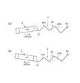
- FIG. 10 is a side view showing another example of the mounting position of the bending assist member 10.
- the flexible printed substrate 9 is bent so that the second surface 902 has a mountain-folded shape. Therefore, in the example shown in FIG. 10, the bending assist member 10 is attached to the second surface 902 of the second folded-back portion 974.
- the bending auxiliary member 10 is attached to the surface having a mountain fold shape. Therefore, in both the first folded-back portion 973 and the second folded-back portion 974, the folded-back portion can be held by the bending auxiliary member 10 from the outer peripheral side. Further, in such a configuration, when the flexible printed substrate 9 and the bending assisting member 10 are bent by using the die 110 and the punches 120 to 140 as in the above embodiment, the flexible printed substrate 9 and the bending assisting member 10 are pressed from the side of the bending assisting member 10 instead of the flexible printed substrate 9. Can be transformed. Therefore, it is possible to reduce the possibility that the wiring in the flexible printed substrate 9 will be broken due to the pressing force.
- the bending auxiliary member 10 is a rectangular plate-shaped member, but it may have another shape.
- 11 (a) and 11 (b) are explanatory views of a bending auxiliary member of a modified example.
- the bending auxiliary member 10A shown in FIG. 11A has a first fixing portion 11 fixed to the first inclined portion 971, a second fixing portion 12 fixed to the second inclined portion 972, and a first fixing portion 11.
- a bent portion 13A for connecting the second fixing portion 12 and the second fixing portion 12 is provided.
- the first fixing portion 11 and the second fixing portion 12 extend substantially parallel to each other in the width direction of the flexible printed substrate 9, as in the above embodiment.
- the bent portion 13A connects a part of the first fixing portion 11 and the second fixing portion 12 in the width direction. In the example shown in FIG. 11A, the bent portion 13A connects the end portion of the first fixing portion 11 and the second fixing portion 12 on one side in the Y direction.
- the bending auxiliary member 10B shown in FIG. 11B has a first fixing portion 11 fixed to the first inclined portion 971, a second fixing portion 12 fixed to the second inclined portion 972, and a first fixing portion 11.
- a bending portion 13B for connecting the second fixing portion 12 and the second fixing portion 12 is provided.
- the first fixing portion 11 and the second fixing portion 12 extend substantially parallel to each other in the width direction of the flexible printed substrate 9, as in the above embodiment.
- the bent portion 13B includes a first bent portion 14 that connects one end (one end in the width direction) of the first fixed portion 11 and the second fixed portion 12 in the Y direction, and the first fixed portion 11 and the second fixed portion.
- a second bent portion 15 for connecting the other end portion (the other end in the width direction) of the portion 12 in the Y direction is provided.
- the weight of the bending assisting member 10A can be reduced.
- the bent portions 13A and 13B have a smaller width in the Y direction than the bent portion 13 of the above-described embodiment, they can be easily bent.
- 122, 131, 132, 141 can also have the same width as the bent portions 13A, 13B. This makes it possible to reduce the size of the die 110 and the punches 120, 130, 140.
- the pressing force is applied only in the range where the bent portions 13A and 13B overlap. Therefore, it is possible to reduce the possibility that the wiring in the flexible printed substrate 9 will be broken due to the pressing force.
Landscapes
- Physics & Mathematics (AREA)
- General Physics & Mathematics (AREA)
- Engineering & Computer Science (AREA)
- Microelectronics & Electronic Packaging (AREA)
- Adjustment Of Camera Lenses (AREA)
- Structure Of Printed Boards (AREA)
Abstract
Description
図1は、本発明を適用した振れ補正機能付き光学ユニット1の平面図であり、図2は、本発明を適用した振れ補正機能付き光学ユニット1の側面図である。なお、図1、図2では、振れ補正機能付き光学ユニット1の構成の一部は模式的に表示するか、あるいは、図示を省略している。
図1に示すように、フレキシブルプリント基板9は、X軸方向へ延びる2本のフレキシブルプリント基板9A、9Bを備える。フレキシブルプリント基板9A、9Bは、可動体5の揺動中心Pを通りXZ面に平行な仮想面Vを基準として対称に構成される。フレキシブルプリント基板9A、9Bは、それぞれ、可動体5から+X方向へ引き出される引き出し部91と、引き出し部91から+X方向へ延びる撓み部92と、撓み部92に接続される被固定部93を備える。本形態では、フレキシブルプリント基板9A、9Bの被固定部93は繋がっている。
図5は、フレキシブルプリント基板9の折り曲げ加工に用いる加工具および加工前のフレキシブルプリント基板9の斜視図である。図5に示すように、加工具は、ダイ110とパンチ120、130、140から構成される。ダイ110は、撓み部92の曲げ形状と同一形状になるように配置される受け面111、112、113、114、115を備えるとともに、可動体5を配置するための凹部116を備える。
以上のように、本形態の振れ補正機能付き光学ユニットは、光学モジュール4を備える可動体5と、固定体8と、互いに直交する3軸をX軸、Y軸、Z軸とし、光学モジュール4の光軸に沿う方向をZ軸としたとき、固定体8に対して可動体5をX軸回りに揺動可能に支持すると共に、可動体5をY軸回りに揺動可能に支持する揺動支持機構と、固定体8に対して可動体5をZ軸回りに揺動可能に支持するローリング支持機構と、可動体5をX軸回りおよびY軸回りに揺動させる揺動用駆動機構6と、可動体5をZ軸回りに揺動させるローリング用駆動機構7と、可動体5から引き出されるフレキシブルプリント基板9と、を有する。フレキシブルプリント基板9は、可動体5からX軸方向へ引き出される引き出し部91と、可動体5からX軸方向に離間した位置で固定体8に固定される被固定部93と、引き出し部91と被固定部93との間に配置される1または複数の折り曲げ部97A、97Bと、を備える。折り曲げ部97A、97Bは、X軸方向の一方側へ向かうにしたがってZ軸方向の一方側へ向かう方向へ延びる第1傾斜部971と、第1折り返し部973を介して第1傾斜部971に接続されX軸方向の一方側へ向かうにしたがってZ軸方向の他方側へ向かう方向へ延びる第2傾斜部972と、を備える。第1傾斜部971と第2傾斜部972は、Z軸方向から見た場合に、第1折り返し部973を介してY軸方向に折り返した形状に接続されている。
(1)上記形態は、撓み部92に2つの折り曲げ部97A、97Bおよび折り曲げ部の半分の形状(第1傾斜部971)が設けられているが、折り曲げ部は、少なくとも1つあればよく、3以上でもよい。また、折り曲げ部の半分の形状(第1傾斜部971)を含めなくてもよい。折り曲げ部の半分の形状を含めない場合には、被固定部93は第2傾斜部972に接続される。従って、この場合には、被固定部93は第2傾斜部972と同一方向に傾斜し、第2傾斜部972と同一方向へ延びている構成を採用すればよい。
Claims (11)
- 光学モジュールを備える可動体と、
固定体と、
互いに直交する3軸をX軸、Y軸、Z軸とし、前記光学モジュールの光軸に沿う方向を前記Z軸としたとき、前記固定体に対して前記可動体を前記X軸回りに揺動可能に支持すると共に、前記可動体を前記Y軸回りに揺動可能に支持する揺動支持機構と、
前記固定体に対して前記可動体を前記Z軸回りに揺動可能に支持するローリング支持機構と、
前記可動体を前記X軸回りおよび前記Y軸回りに揺動させる揺動用駆動機構と、
前記可動体を前記Z軸回りに揺動させるローリング用駆動機構と、
前記可動体から引き出されるフレキシブルプリント基板と、を有し、
前記フレキシブルプリント基板は、前記可動体から前記X軸方向へ引き出される引き出し部と、前記可動体から前記X軸方向に離間した位置で前記固定体に固定される被固定部と、前記引き出し部と前記被固定部との間に配置される1または複数の折り曲げ部と、を備え、
前記折り曲げ部は、
前記X軸方向の一方側へ向かうにしたがって前記Z軸方向の一方側へ向かう方向へ延びる第1傾斜部と、第1折り返し部を介して前記第1傾斜部に接続され前記X軸方向の一方側へ向かうにしたがって前記Z軸方向の他方側へ向かう方向へ延びる第2傾斜部と、を備え、
前記第1傾斜部と前記第2傾斜部は、前記Z軸方向から見た場合に、前記第1折り返し部を介して前記Y軸方向に折り返した形状であることを特徴とする振れ補正機能付き光学ユニット。 - 前記X軸方向に並ぶ複数の前記折り曲げ部を備え、
最も前記可動体に近い前記折り曲げ部は、他の前記折り曲げ部よりも前記Z軸方向の高さが小さいことを特徴とする請求項1に記載の振れ補正機能付き光学ユニット。 - 前記X軸方向で隣り合う前記折り曲げ部を接続する第2折り返し部を備え、
前記第2折り返し部と前記第1折り返し部は、前記Y軸方向の位置が異なることを特徴とする請求項1または2に記載の振れ補正機能付き光学ユニット。 - 前記第1折り返し部および前記第2折り返し部に取り付けられた曲げ補助部材を備えることを特徴とする請求項3に記載の振れ補正機能付き光学ユニット。
- 前記フレキシブルプリント基板は、第1表面、および、前記第1表面の裏側を向く第2表面を備え、
前記第1表面と前記第2表面の一方に全ての前記曲げ補助部材が取り付けられていることを特徴とする請求項4に記載の振れ補正機能付き光学ユニット。 - 前記フレキシブルプリント基板は、第1表面、および、前記第1表面の裏側を向く第2表面を備え、
前記第1折り返し部では、前記第1表面が山折り形状となるように前記フレキシブルプリント基板が折り曲げられており、且つ、前記曲げ補助部材が前記第1表面に取り付けられており、
前記第2折り返し部では、前記第2表面が山折り形状となるように前記フレキシブルプリント基板が折り曲げられており、且つ、前記曲げ補助部材が前記第2表面に取り付けられていることを特徴とする請求項4に記載の振れ補正機能付き光学ユニット。 - 前記曲げ補助部材は、前記第1傾斜部に固定される第1固定部と、前記第2傾斜部に固定される第2固定部と、前記第1固定部と前記第2固定部とを接続する曲げ部と、を備え、
前記第1固定部および前記第2固定部は、前記フレキシブルプリント基板の幅方向に延びており、前記曲げ部は、前記第1固定部と前記第2固定部の前記幅方向の一部を接続することを特徴とする請求項4から6の何れか一項に記載の振れ補正機能付き光学ユニット。 - 前記曲げ部は、
前記第1固定部と前記第2固定部の前記幅方向の一端を接続する第1曲げ部と、
前記第1固定部と前記第2固定部の前記幅方向の他端を接続する第2曲げ部と、を備えることを特徴とする請求項7に記載の振れ補正機能付き光学ユニット。 - 前記被固定部は、前記第1傾斜部および前記第2傾斜部の一方に接続され、
前記被固定部は、前記第1傾斜部および前記第2傾斜部の一方と同一方向へ延びていることを特徴とする請求項1から8の何れか一項に記載の振れ補正機能付き光学ユニット。 - 前記Y軸方向に並ぶ2本の前記フレキシブルプリント基板を備え、
前記2本の前記フレキシブルプリント基板は、前記可動体の揺動中心を通りXZ平面に平行な仮想面を基準として対称に構成されていることを特徴とする請求項1から9の何れか一項に記載の振れ補正機能付き光学ユニット。 - 請求項1から10の何れか一項に記載の振れ補正機能付き光学ユニットが備えるフレキシブルプリント基板の折り曲げ方法であって、
平面内において折り返した形状の前記フレキシブルプリント基板を、前記折り曲げ部の折り曲げ形状と一致する形状の受け面を備えるダイにセットし、
前記受け面の反転形状の押圧面を備えるパンチによって前記フレキシブルプリント基板を前記受け面に押し付けることにより、前記フレキシブルプリント基板を前記折り曲げ部の形状に折り曲げることを特徴とするフレキシブルプリント基板の折り曲げ方法。
Priority Applications (2)
| Application Number | Priority Date | Filing Date | Title |
|---|---|---|---|
| CN202180060949.9A CN116194833B (zh) | 2020-07-16 | 2021-06-18 | 带抖动修正功能的光学单元及柔性印刷基板的折弯方法 |
| JP2022536189A JPWO2022014254A1 (ja) | 2020-07-16 | 2021-06-18 |
Applications Claiming Priority (2)
| Application Number | Priority Date | Filing Date | Title |
|---|---|---|---|
| JP2020122045 | 2020-07-16 | ||
| JP2020-122045 | 2020-07-16 |
Publications (1)
| Publication Number | Publication Date |
|---|---|
| WO2022014254A1 true WO2022014254A1 (ja) | 2022-01-20 |
Family
ID=79555199
Family Applications (1)
| Application Number | Title | Priority Date | Filing Date |
|---|---|---|---|
| PCT/JP2021/023130 Ceased WO2022014254A1 (ja) | 2020-07-16 | 2021-06-18 | 振れ補正機能付き光学ユニットおよびフレキシブルプリント基板の折り曲げ方法 |
Country Status (3)
| Country | Link |
|---|---|
| JP (1) | JPWO2022014254A1 (ja) |
| CN (1) | CN116194833B (ja) |
| WO (1) | WO2022014254A1 (ja) |
Citations (5)
| Publication number | Priority date | Publication date | Assignee | Title |
|---|---|---|---|---|
| WO2015016043A1 (ja) * | 2013-08-01 | 2015-02-05 | 富士フイルム株式会社 | 撮像モジュール及び電子機器 |
| WO2015104960A1 (ja) * | 2014-01-09 | 2015-07-16 | 富士フイルム株式会社 | 撮像モジュール、撮像モジュールの製造方法、電子機器 |
| CN111443550A (zh) * | 2020-05-28 | 2020-07-24 | 河南皓泽电子股份有限公司 | 防抖云台 |
| JP2020166177A (ja) * | 2019-03-29 | 2020-10-08 | 日本電産サンキョー株式会社 | 光学ユニットの製造方法 |
| KR20200142688A (ko) * | 2019-06-13 | 2020-12-23 | 주식회사 엠씨넥스 | 광학 흔들림 보정 기능을 구비한 카메라 모듈 |
Family Cites Families (6)
| Publication number | Priority date | Publication date | Assignee | Title |
|---|---|---|---|---|
| JP2010040720A (ja) * | 2008-08-04 | 2010-02-18 | Sharp Corp | フレキシブルプリント配線板、電子機器モジュールおよび電子情報機器 |
| JP5593118B2 (ja) * | 2010-04-30 | 2014-09-17 | 日本電産サンキョー株式会社 | 振れ補正機能付き光学ユニット |
| JP6460745B2 (ja) * | 2014-11-21 | 2019-01-30 | 日本電産サンキョー株式会社 | 振れ補正機能付き光学ユニット |
| JP6779104B2 (ja) * | 2016-11-10 | 2020-11-04 | 日本電産サンキョー株式会社 | 振れ補正機能付き光学ユニット |
| JP6921579B2 (ja) * | 2017-03-30 | 2021-08-18 | 日本電産サンキョー株式会社 | 振れ補正機能付き光学ユニット |
| JP7046512B2 (ja) * | 2017-07-12 | 2022-04-04 | 日本電産サンキョー株式会社 | ローリング補正機能付き光学ユニットおよび3軸振れ補正機能付き光学ユニット |
-
2021
- 2021-06-18 JP JP2022536189A patent/JPWO2022014254A1/ja active Pending
- 2021-06-18 CN CN202180060949.9A patent/CN116194833B/zh active Active
- 2021-06-18 WO PCT/JP2021/023130 patent/WO2022014254A1/ja not_active Ceased
Patent Citations (5)
| Publication number | Priority date | Publication date | Assignee | Title |
|---|---|---|---|---|
| WO2015016043A1 (ja) * | 2013-08-01 | 2015-02-05 | 富士フイルム株式会社 | 撮像モジュール及び電子機器 |
| WO2015104960A1 (ja) * | 2014-01-09 | 2015-07-16 | 富士フイルム株式会社 | 撮像モジュール、撮像モジュールの製造方法、電子機器 |
| JP2020166177A (ja) * | 2019-03-29 | 2020-10-08 | 日本電産サンキョー株式会社 | 光学ユニットの製造方法 |
| KR20200142688A (ko) * | 2019-06-13 | 2020-12-23 | 주식회사 엠씨넥스 | 광학 흔들림 보정 기능을 구비한 카메라 모듈 |
| CN111443550A (zh) * | 2020-05-28 | 2020-07-24 | 河南皓泽电子股份有限公司 | 防抖云台 |
Also Published As
| Publication number | Publication date |
|---|---|
| CN116194833B (zh) | 2025-08-08 |
| CN116194833A (zh) | 2023-05-30 |
| JPWO2022014254A1 (ja) | 2022-01-20 |
Similar Documents
| Publication | Publication Date | Title |
|---|---|---|
| CN111538165B (zh) | 带抖动修正功能的光学单元及带抖动修正功能的光学单元的制造方法 | |
| JP6921579B2 (ja) | 振れ補正機能付き光学ユニット | |
| JP2021139988A (ja) | 振れ補正機能付き光学ユニット | |
| JP7376279B2 (ja) | 振れ補正機能付き光学ユニット | |
| US11997793B2 (en) | Optical unit | |
| US11627663B2 (en) | Optical unit | |
| CN113946080B (zh) | 带抖动修正功能的光学单元 | |
| JP6869772B2 (ja) | 振れ補正機能付き光学ユニットおよび振れ補正機能付き光学ユニットの製造方法 | |
| JP7411445B2 (ja) | 光学ユニット | |
| JP2021015235A (ja) | 振れ補正機能付き光学ユニット | |
| JP2021039292A (ja) | 振れ補正機能付き光学ユニット | |
| CN117376668A (zh) | 布线基板、带抖动修正功能的光学单元及其制造方法 | |
| CN116194833B (zh) | 带抖动修正功能的光学单元及柔性印刷基板的折弯方法 | |
| JP2020166177A (ja) | 光学ユニットの製造方法 | |
| CN114679522B (zh) | 带抖动修正功能的光学单元 | |
| JP7734069B2 (ja) | 振れ補正機能付き光学ユニット | |
| CN116149112B (zh) | 带抖动修正功能的光学单元 | |
| JP7611057B2 (ja) | 光学ユニット | |
| JP7686495B2 (ja) | 振れ補正機能付き光学ユニット | |
| US12474539B2 (en) | Optical unit | |
| CN115201987B (zh) | 光学单元 | |
| JP2024008168A (ja) | 振れ補正機能付き光学ユニット | |
| CN117641101A (zh) | 带抖动修正功能的光学单元 | |
| JP2022169900A (ja) | 振れ補正機能付き光学ユニット |
Legal Events
| Date | Code | Title | Description |
|---|---|---|---|
| 121 | Ep: the epo has been informed by wipo that ep was designated in this application |
Ref document number: 21841513 Country of ref document: EP Kind code of ref document: A1 |
|
| ENP | Entry into the national phase |
Ref document number: 2022536189 Country of ref document: JP Kind code of ref document: A |
|
| NENP | Non-entry into the national phase |
Ref country code: DE |
|
| 122 | Ep: pct application non-entry in european phase |
Ref document number: 21841513 Country of ref document: EP Kind code of ref document: A1 |
|
| WWG | Wipo information: grant in national office |
Ref document number: 202180060949.9 Country of ref document: CN |