WO2022014157A1 - アンテナ装置 - Google Patents
アンテナ装置 Download PDFInfo
- Publication number
- WO2022014157A1 WO2022014157A1 PCT/JP2021/019351 JP2021019351W WO2022014157A1 WO 2022014157 A1 WO2022014157 A1 WO 2022014157A1 JP 2021019351 W JP2021019351 W JP 2021019351W WO 2022014157 A1 WO2022014157 A1 WO 2022014157A1
- Authority
- WO
- WIPO (PCT)
- Prior art keywords
- antenna device
- modification
- vehicle
- circuit board
- wireless communication
- Prior art date
- Legal status (The legal status is an assumption and is not a legal conclusion. Google has not performed a legal analysis and makes no representation as to the accuracy of the status listed.)
- Ceased
Links
Images






Classifications
-
- H—ELECTRICITY
- H01—ELECTRIC ELEMENTS
- H01Q—ANTENNAS, i.e. RADIO AERIALS
- H01Q1/00—Details of, or arrangements associated with, antennas
- H01Q1/12—Supports; Mounting means
- H01Q1/22—Supports; Mounting means by structural association with other equipment or articles
-
- H—ELECTRICITY
- H01—ELECTRIC ELEMENTS
- H01Q—ANTENNAS, i.e. RADIO AERIALS
- H01Q1/00—Details of, or arrangements associated with, antennas
- H01Q1/27—Adaptation for use in or on movable bodies
- H01Q1/32—Adaptation for use in or on road or rail vehicles
-
- H—ELECTRICITY
- H01—ELECTRIC ELEMENTS
- H01Q—ANTENNAS, i.e. RADIO AERIALS
- H01Q15/00—Devices for reflection, refraction, diffraction or polarisation of waves radiated from an antenna, e.g. quasi-optical devices
- H01Q15/14—Reflecting surfaces; Equivalent structures
-
- H—ELECTRICITY
- H01—ELECTRIC ELEMENTS
- H01Q—ANTENNAS, i.e. RADIO AERIALS
- H01Q9/00—Electrically-short antennas having dimensions not more than twice the operating wavelength and consisting of conductive active radiating elements
- H01Q9/04—Resonant antennas
- H01Q9/16—Resonant antennas with feed intermediate between the extremities of the antenna, e.g. centre-fed dipole
Definitions
- the present invention relates to an antenna device.
- Patent Document 1 below includes a dipole antenna provided inside a vehicle door handle, and is used for a vehicle that emits UHF band radio waves toward a communication area set around the vehicle door through the antenna.
- the antenna device is disclosed.
- the strength of radio waves radiated to the communication area is obtained by forming a gap between the outer panel of the vehicle door and the dipole antenna and using the outer panel of the vehicle door as a reflective surface. The technology to strengthen the door is disclosed.
- the inventors of the present invention relate to an antenna device mounted on an exterior component (for example, a door mirror, a door handle, etc.) outside the vehicle body in a vehicle, and the vehicle body generated by radiating radio waves from the antenna device to the vehicle body. It has been found that the reflected wave from the antenna device may affect the radiation characteristics of the antenna device in the outward direction of the vehicle body.
- an exterior component for example, a door mirror, a door handle, etc.
- the antenna device is an antenna device mounted on an exterior component on the outside of a vehicle body in a vehicle, and includes a radiating element and a reflecting element arranged on the vehicle body side of the radiating element.
- the influence of the vehicle body on the radiation characteristics can be suppressed.
- the figure which shows the 3rd modification of the reflection element which concerns on one Embodiment The figure which shows the radiation characteristic in the horizontal plane (XY plane) of the antenna device which concerns on 3rd modification.
- the figure which shows the 4th modification of the reflection element which concerns on one Embodiment The figure which shows the radiation characteristic in the horizontal plane (XY plane) of the antenna device which concerns on 4th modification.
- the direction corresponding to the height direction of the vehicle on which the antenna device 100 is mounted is the vertical direction (Z-axis direction), and the direction corresponding to the length direction of the vehicle is the front-rear direction (X-axis).
- Direction the direction corresponding to the width direction of the vehicle is the left-right direction (Y-axis direction).
- FIG. 1 is a diagram showing an arrangement of an antenna device 100 according to an embodiment.
- the antenna device 100 is mounted on a right door mirror 10 (an example of an "exterior component" of a vehicle such as an automobile.
- the antenna device 100 is a communication circuit (non-standard) that performs wireless communication between an in-vehicle device (for example, an ECU (Electronic Control Unit)) mounted on a vehicle and the outside of the vehicle provided on the antenna device 100 via a power supply cable 110. It is a device that can be connected to (shown) and can perform wireless communication with the outside of the vehicle.
- an in-vehicle device for example, an ECU (Electronic Control Unit) mounted on a vehicle and the outside of the vehicle provided on the antenna device 100 via a power supply cable 110.
- ECU Electronic Control Unit
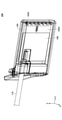
- the antenna device 100 includes a housing 102 having a substantially thin rectangular parallelepiped shape. As shown in FIG. 1, the antenna device 100 is attached to the right door mirror 10 so that the surface 102A of the housing 102 is perpendicular to the ground (XY plane) and the surface 102A faces the rear (X-axis positive direction). It will be installed.
- the mirror surface 10A of the right door mirror 10 is formed by printing or thin-filming metal fine particles. As a result, the mirror surface 10A can reflect the light incident on the mirror surface 10A and can transmit the radio wave radiated from the antenna device 100.
- the antenna device 100 mounted on the right door mirror 10 of the vehicle will be described, but the left door mirror of the vehicle is also configured to be symmetrical with the antenna device 100 provided on the right door mirror 10.
- An antenna device may be provided.
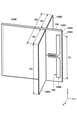
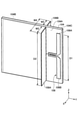
- FIG. 2 is an external perspective view of the antenna device 100 according to the embodiment.
- FIG. 3 is a partial perspective view of the antenna device 100 according to the embodiment.
- FIG. 4 is an external perspective view of the circuit board 104 according to the embodiment.
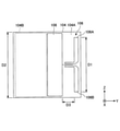
- FIG. 5 is a plan view of the circuit board 104 according to the embodiment.
- the antenna device 100 includes a housing 102, a circuit board 104, a radiation element 106, a reflection element 108, and a power feeding cable 110.
- the housing 102 has the outer shape of the antenna device 100 and is a container-shaped member that houses each component of the antenna device 100.
- the housing 102 is formed by using a resin material.
- the housing 102 has a substantially rectangular parallelepiped shape that is thin in the front-rear direction (X-axis direction).
- the circuit board 104 is a hard and flat member provided inside the housing 102.
- the surface 104A of the circuit board 104 has a rectangular shape in a plan view.
- a PWB (Printed Wired Board) or the like is used for the circuit board 104.
- a communication circuit for wireless communication with the outside of the vehicle is formed on the surface 104A of the circuit board 104.
- the circuit board 104 is perpendicular to the ground by arranging the housing 102 perpendicular to the ground (XY plane), and the surface 104A is rearward (X). Axial positive direction).
- the radiating element 106 is formed as a copper foil pattern on the surface 104A of the circuit board 104.
- the radiating element 106 has a flat plate shape horizontal to the surface 104A.
- the radiating element 106 may be formed by using a conductive thin film-like, thin plate-like, linear or rod-like material.
- the radiating element 106 is a so-called dipole antenna, and has a first element 106A and a second element 106B as shown in FIGS. 4 and 5.
- the elements 106A and 106B have a strip shape extending linearly from an intermediate position between the two elements in different directions in a plan view.
- the first element 106A extends linearly toward the outside direction (Y-axis positive direction) of the vehicle at an intermediate position in the vertical direction (Z-axis direction) of the surface 104A, and then bends at a right angle and upwards (Z). It has a strip extending linearly in the positive direction of the axis).
- the second element 106B is provided below the first element 106A and has a symmetrical shape with respect to the first element 106A.
- the second element 106B extends linearly toward the outside direction (Y-axis positive direction) of the vehicle at an intermediate position in the vertical direction (Z-axis direction) of the surface 104A, and then bends at a right angle and downwards (Z). It has a strip extending linearly in the negative axis direction).
- the radiating element 106 transmits and receives radio waves of a specific frequency used for wireless communication by being connected to a communication circuit that performs wireless communication with the outside of the vehicle. Therefore, as shown in FIG. 5, the radiating element 106 has a total length D1 (length in the Z-axis direction) of 1/2 wavelength of a specific frequency used for wireless communication.
- the reflective element 108 is formed as a copper foil pattern on the surface 104A of the circuit board 104 on the vehicle body side (Y-axis negative side) of the radiating element 106.
- the reflecting element 108 has a flat plate shape horizontal to the surface 104A.
- the reflective element 108 may be formed by using a conductive thin film-like, thin plate-like, linear or rod-like material.
- the reflecting element 108 has a rectangular shape in a plan view. As shown in FIG. 5, the reflecting element 108 has a total length D2 (length in the Z-axis direction).
- the total length D2 of the reflecting element 108 is larger than the total length D1 of the radiating element 106 (that is, 1/2 wavelength of a specific frequency used for wireless communication).
- the reflecting element 108 suppresses the influence of the vehicle body on the radio waves transmitted and received by the radiating element 106.
- the separation distance D3 (see FIG. 5) between the radiating element 106 and the reflecting element 108 is preferably 0.2 to 0.3 wavelength of a specific frequency used for wireless communication.
- the antenna device 100 of the present embodiment has a reflective element having the same shape as the circuit mounting area 104B in the rectangular circuit mounting area 104B (see FIG. 5) on the surface 104A of the circuit board 104. 108 is provided. That is, in the antenna device 100 of the present embodiment, a part of the reflective element 108 is actually cut off, and various electronic components constituting a communication circuit for wireless communication with the outside of the vehicle are provided in the cut-off part. Has been done.
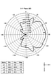
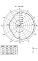
- FIG. 6 is a diagram showing radiation characteristics in the horizontal plane (XY plane) of the antenna device for comparison.
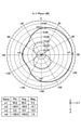
- FIG. 7 is a diagram showing radiation characteristics in a horizontal plane (XY plane) of the antenna device 100 according to the embodiment.
- the radiation characteristics of the radio waves (vertically polarized waves) radiated from the radiation element 106 are simulated for each of the antenna device 100 according to the embodiment and the antenna device for comparison.
- the antenna device for comparison the antenna device 100 from which the reflecting element 108 has been removed is used.
- the antenna device for comparison and the antenna device 100 according to the embodiment are both in the horizontal plane (XY plane) in the Y-axis positive direction (of the vehicle) with the antenna device as the center. It has a substantially semi-circular radial pattern in the outward direction).
- the antenna characteristic of the antenna device for comparison is the positive direction of the Y axis in the horizontal plane (XY plane) due to the influence of the reflected wave from the vehicle body due to the radiation of radio waves to the vehicle body.
- Null compression
- the antenna characteristic of the antenna device 100 according to the embodiment is a horizontal plane because the radiation of radio waves to the vehicle body is suppressed by the reflecting element 108 and the influence of the vehicle body on the radio waves is suppressed.
- the generation of Null is suppressed.
- the antenna device 100 can suppress the influence of the vehicle body on the radiation characteristics by providing the reflection element 108 on the vehicle body side of the radiation element 106. It was confirmed that.
- the antenna device 100 is not limited to the door mirror, and may be mounted on other exterior parts (for example, a door handle).
- FIG. 8 is a diagram showing a first modification of the reflective element 108 according to the embodiment.
- a rectangular reflecting element 108 is provided on the surface 104A of the circuit board 104 on the vehicle body side (Y-axis negative side) of the radiating element 106.
- a rectangular circuit mounting area 104B is provided on the vehicle body side (Y-axis negative side) of the reflection element 108.
- the total length D2 of the reflecting element 108 is the total length D1 of the radiating element 106 (that is, 1/2 wavelength of a specific frequency used for wireless communication). Greater than. Also in the antenna device 100 according to the first modification, the influence of the vehicle body on the radio wave can be suppressed by providing the reflection element 108 on the vehicle body side with respect to the radiation element 106.
- FIG. 9 is a diagram showing a second modification of the reflective element 108 according to the embodiment.
- FIG. 10 is a diagram showing radiation characteristics in a horizontal plane (XY plane) of the antenna device 100 according to the second modification.
- XY plane horizontal plane
- FIG. 9 in the antenna device 100 according to the second modification, a rectangular circuit mounting area 104B is provided on the surface 104A of the circuit board 104 on the vehicle body side (Y-axis negative side) of the radiation element 106. has been done.
- the device 100 is erected between the circuit mounting area 104B and the radiating element 106 (the end of the circuit mounting area 104B on the positive side of the Y axis) perpendicular to the surface 104A.
- a first reflecting element 108A is provided. Further, in the antenna device 100 according to the second modification, the second reflecting element 108B is provided vertically with respect to the surface 104C on the back side of the surface 104A in the circuit board 104. Both the first reflecting element 108A and the second reflecting element 108B have a rectangular shape in which the vertical direction (Z-axis direction) is the longitudinal direction and the front-back direction (X-axis direction) is the lateral direction in a plan view. Has. The first reflecting element 108A and the second reflecting element 108B are electrically coupled to each other.
- both the first reflecting element 108A and the second reflecting element 108B have a constant width W1 in the front-rear direction (X-axis direction). Further, in the antenna device 100 according to the second modification, the total width W2 obtained by adding the width W1 of the first reflecting element 108A and the width W1 of the second reflecting element 108B is a specific frequency used for wireless communication. It is set to be equal to or longer than 1/2 wavelength of. Both the first reflecting element 108A and the second reflecting element 108B are formed by using a metal plate, and are fixed to the surface 104A and the surface 104C of the circuit board 104 by soldering or the like.
- the total length D2 of each of the first reflecting element 108A and the second reflecting element 108B is the total length D1 of the radiation element 106 (that is, wireless communication). It is larger than 1/2 wavelength of the specific frequency used for. Also in the antenna device 100 according to the second modification, the influence of the vehicle body on the radiation characteristics is suppressed by providing the first reflection element 108A and the second reflection element 108B on the vehicle body side of the radiation element 106. Can be done.
- the total width W2 obtained by adding the width W1 of the first reflecting element 108A and the width W1 of the second reflecting element 108B has a specific frequency used for wireless communication. Since it is set to be equal to or longer than 1/2 wavelength of, as shown in FIG. 10, the spread of the radiation characteristic in the X-axis direction can be narrowed, and the antenna can be adjusted to the desired communication region. The radiation characteristics of can be adjusted.
- the circuit mounting area 104B is narrowed by erection of the first reflecting element 108A and the second reflecting element 108B while avoiding the circuit mounting area 104B. Can be suppressed.
- FIG. 11 is a diagram showing a third modification of the reflective element 108 according to the embodiment.
- FIG. 12 is a diagram showing radiation characteristics in a horizontal plane (XY plane) of the antenna device 100 according to the third modification.
- XY plane horizontal plane
- both the first reflecting element 108A and the second reflecting element 108B electrically coupled to each other are in the front-rear direction (X-axis direction).
- W3 width W3 (however, W3 ⁇ W1).
- the total width W4 obtained by adding the width W3 of the first reflecting element 108A and the width W3 of the second reflecting element 108B is a specific frequency used for wireless communication. It is smaller than 1/2 wavelength of.
- the total width W4 which is the sum of the width W3 of the first reflecting element 108A and the width W3 of the second reflecting element 108B, is 1 of a specific frequency used for wireless communication. Since it is set to be shorter than / 2 wavelengths, as shown in FIG. 12, the spread of the radiation characteristics in the X-axis direction can be widened, and the radiation characteristics of the antenna can be adjusted according to the desired communication region. Can be adjusted.
- FIG. 13 is a diagram showing a fourth modification of the reflective element 108 according to the embodiment.
- FIG. 14 is a diagram showing radiation characteristics in a horizontal plane (XY plane) of the antenna device 100 according to the fourth modification.
- the antenna device 100 according to the fourth modification includes a reflecting element 109 on the surface 104A of the circuit board 104 on the outer side (Y-axis positive side) of the radiating element 106. That is, the antenna device 100 according to the fourth modification includes reflecting elements 108 and 109 on both the left and right sides of the radiating element 106.
- the antenna device 100 according to the fourth modification can suppress radiation in the outward direction (Y-axis positive direction) of the vehicle, while increasing radiation in the front-rear direction (X-axis direction).
- the antenna device 100 according to the fourth modification can make the radiation pattern in the positive direction of the Y axis in the horizontal plane (XY plane) uniform.
- FIG. 15 is a diagram showing a fifth modification of the reflective element 108 according to the embodiment.
- FIG. 16 is a diagram showing radiation characteristics in a horizontal plane (XY plane) of the antenna device 100 according to the fifth modification.
- the antenna device 100 according to the fifth modification is an antenna according to the fourth modification in that the waveguide elements 111A and 111B are further provided in the configuration of the antenna device 100 according to the fourth modification. Different from device 100.
- the waveguide element 111A is arranged behind the radiation element 106 (in the positive direction of the X-axis) and separated from the surface 104A of the circuit board 104.
- the waveguide element 111B is arranged in front of the radiation element 106 (in the negative direction on the X-axis) so as to be separated from the surface 104C of the circuit board 104.
- the antenna device 100 according to the fifth modification can guide the radiation in the outer direction (Y-axis positive direction) of the vehicle in each of the X-axis positive direction and the X-axis negative direction by the waveguide effect. ..
- the antenna device 100 according to the fifth modification can further make the radiation pattern in the positive direction of the Y axis in the horizontal plane (XY plane) more uniform.
Landscapes
- Physics & Mathematics (AREA)
- Electromagnetism (AREA)
- Details Of Aerials (AREA)
- Support Of Aerials (AREA)
- Aerials With Secondary Devices (AREA)
Abstract
アンテナ装置は、車両における車体の外側の外装部品に搭載されるアンテナ装置であって、放射素子と、放射素子よりも車体側に配置された反射素子とを備える。
Description
本発明は、アンテナ装置に関する。
例えば、下記特許文献1には、車両のドアハンドルの内部に設けられたダイポールアンテナを備え、該アンテナを通じて車両ドアの周辺に設定された通信エリアに向けてUHF帯の無線電波を放射する車両用アンテナ装置が開示されている。また、下記特許文献1には、車両ドアのアウタパネルとダイポールアンテナとの間に間隙を形成したうえで、車両ドアのアウタパネルを反射面として利用することで、通信エリアに放射される無線電波の強度を強める技術が開示されている。
ところで、本発明の発明者らは、車両における車体の外側の外装部品(例えば、ドアミラー、ドアハンドル等)に搭載されるアンテナ装置に関し、当該アンテナ装置から車体に電波が放射されることによって生じる車体からの反射波が、当該アンテナ装置の車体の外側方向への放射特性に影響を及ぼす虞があることを見出した。
一実施形態に係るアンテナ装置は、車両における車体の外側の外装部品に搭載されるアンテナ装置であって、放射素子と、放射素子よりも車体側に配置された反射素子とを備える。
一実施形態によれば、車体による放射特性への影響を抑制することができる。
以下、図面を参照して、一実施形態について説明する。なお、本実施形態では、アンテナ装置100が搭載される車両の高さ方向に対応する方向を、上下方向(Z軸方向)とし、車両の長さ方向に対応する方向を、前後方向(X軸方向)とし、車両の幅方向に対応する方向を、左右方向(Y軸方向)とする。
(アンテナ装置100の概要)
図1は、一実施形態に係るアンテナ装置100の配置を示す図である。図1に示すように、アンテナ装置100は、自動車等の車両の右ドアミラー10(「外装部品」の一例)に搭載される。アンテナ装置100は、給電ケーブル110を介して、車両に搭載された車載装置(例えば、ECU(Electronic Control Unit))とアンテナ装置100に設けられた車両の外部との無線通信を行う通信回路(不図示)とが接続され、車両の外部との無線通信を行うことが可能な装置である。アンテナ装置100が外部との無線通信に使用する無線通信規格としては、例えば、V2X(Vehicle to Everything)等が挙げられる。図1に示すように、アンテナ装置100は、概ね薄型の直方体形状を有する筐体102を備える。図1に示すように、アンテナ装置100は、筐体102の表面102Aが地面(XY平面)に対して垂直となり、且つ表面102Aが後方(X軸正方向)を向くように、右ドアミラー10に搭載される。
図1は、一実施形態に係るアンテナ装置100の配置を示す図である。図1に示すように、アンテナ装置100は、自動車等の車両の右ドアミラー10(「外装部品」の一例)に搭載される。アンテナ装置100は、給電ケーブル110を介して、車両に搭載された車載装置(例えば、ECU(Electronic Control Unit))とアンテナ装置100に設けられた車両の外部との無線通信を行う通信回路(不図示)とが接続され、車両の外部との無線通信を行うことが可能な装置である。アンテナ装置100が外部との無線通信に使用する無線通信規格としては、例えば、V2X(Vehicle to Everything)等が挙げられる。図1に示すように、アンテナ装置100は、概ね薄型の直方体形状を有する筐体102を備える。図1に示すように、アンテナ装置100は、筐体102の表面102Aが地面(XY平面)に対して垂直となり、且つ表面102Aが後方(X軸正方向)を向くように、右ドアミラー10に搭載される。
なお、右ドアミラー10の鏡面10Aは、金属微粒子が印刷または蒸着によって形成されている。これにより、鏡面10Aは、当該鏡面10Aに入射された光を反射することができ、且つ、アンテナ装置100から放射された電波を透過することができる。
また、本実施形態では、車両の右ドアミラー10に搭載されているアンテナ装置100について説明するが、車両の左ドアミラーにも、右ドアミラー10に設けられているアンテナ装置100とは左右対称に構成されたアンテナ装置を設けてもよい。
(アンテナ装置100の構成)
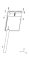
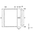
図2は、一実施形態に係るアンテナ装置100の外観斜視図である。図3は、一実施形態に係るアンテナ装置100の一部透視図である。図4は、一実施形態に係る回路基板104の外観斜視図である。図5は、一実施形態に係る回路基板104の平面図である。図2~図4に示すように、アンテナ装置100は、筐体102、回路基板104、放射素子106、反射素子108、および給電ケーブル110を備える。
図2は、一実施形態に係るアンテナ装置100の外観斜視図である。図3は、一実施形態に係るアンテナ装置100の一部透視図である。図4は、一実施形態に係る回路基板104の外観斜視図である。図5は、一実施形態に係る回路基板104の平面図である。図2~図4に示すように、アンテナ装置100は、筐体102、回路基板104、放射素子106、反射素子108、および給電ケーブル110を備える。
筐体102は、アンテナ装置100の外形をなし、アンテナ装置100の各構成部品を収容する容器状の部材である。筐体102は、樹脂素材が用いられて形成される。本実施形態では、筐体102は、前後方向(X軸方向)について薄型の、概ね直方体形状を有する。
回路基板104は、筐体102の内部に設けられる、硬質且つ平板状の部材である。回路基板104の表面104Aは、平面視において矩形状を有する。回路基板104には、PWB(Printed Wired Board)等が用いられる。回路基板104の表面104Aには、車両の外部との無線通信を行う通信回路が形成される。図3および図4に示すように、回路基板104は、筐体102が地面(XY平面)に対して垂直に配置されることにより、地面に対して垂直となり、且つ、表面104Aが後方(X軸正方向)を向く。
放射素子106は、回路基板104の表面104Aに銅箔パターンとして形成されている。放射素子106は、表面104Aに対して水平な平板状を有する。放射素子106は、銅箔パターンで形成する以外に、導電性を有する薄膜状、薄板状、線状または棒状の素材が用いられて形成されても良い。
本実施形態では、放射素子106は、いわゆるダイポールアンテナであり、図4および図5に示すように、第1のエレメント106Aと、第2のエレメント106Bとを有する。エレメント106A,106Bは、平面視において、両者の中間位置から互いに異なる方向に直線状に延在する、帯状を有する。
第1のエレメント106Aは、表面104Aの上下方向(Z軸方向)における中間位置において、車両の外側方向(Y軸正方向)に向かって直線状に延在した後、直角に折れ曲がり、上方(Z軸正方向)に直線状に延在する帯状を有する。
第2のエレメント106Bは、第1のエレメント106Aの下側に設けられており、第1のエレメント106Aに対する対称形状を有する。第2のエレメント106Bは、表面104Aの上下方向(Z軸方向)における中間位置において、車両の外側方向(Y軸正方向)に向かって直線状に延在した後、直角に折れ曲がり、下方(Z軸負方向)に直線状に延在する帯状を有する。
放射素子106は、車両の外部との無線通信を行う通信回路に接続されることにより、無線通信に用いられる特定の周波数の電波の送受信を行う。そのため、放射素子106は、図5に示すように、無線通信に用いられる特定の周波数の1/2波長の全長D1(Z軸方向の長さ)を有する。
反射素子108は、回路基板104の表面104Aにおいて、放射素子106よりも車体側(Y軸負側)に銅箔パターンとして形成されている。反射素子108は、表面104Aに対して水平な平板状を有する。反射素子108は、銅箔パターンで形成する以外に、導電性を有する薄膜状、薄板状、線状または棒状の素材が用いられて形成されても良い。本実施形態では、反射素子108は、平面視において矩形状を有する。反射素子108は、図5に示すように、全長D2(Z軸方向の長さ)を有する。反射素子108の全長D2は、放射素子106の全長D1(すなわち、無線通信に用いられる特定の周波数の1/2波長)よりも大きい。反射素子108は、車体による放射素子106によって送受信される電波への影響を抑制する。なお、放射素子106と反射素子108との離間距離D3(図5参照)は、無線通信に用いられる特定の周波数の0.2~0.3波長であることが好ましい。
なお、図5に示すように、本実施形態のアンテナ装置100は、回路基板104の表面104Aにおける矩形状の回路実装領域104B(図5参照)に、当該回路実装領域104Bと同形状の反射素子108が設けられている。すなわち、本実施形態のアンテナ装置100は、実際には反射素子108の一部が切除されており、その切除部分に、車両の外部との無線通信を行う通信回路を構成する各種電子部品が設けられている。
(実施例)
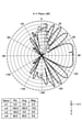
次に、図6および図7を参照して、一実施形態に係るアンテナ装置100の一実施例について説明する。図6は、比較用のアンテナ装置の水平面(XY平面)における放射特性を示す図である。図7は、一実施形態に係るアンテナ装置100の水平面(XY平面)における放射特性を示す図である。
次に、図6および図7を参照して、一実施形態に係るアンテナ装置100の一実施例について説明する。図6は、比較用のアンテナ装置の水平面(XY平面)における放射特性を示す図である。図7は、一実施形態に係るアンテナ装置100の水平面(XY平面)における放射特性を示す図である。
本実施例では、一実施形態に係るアンテナ装置100と、比較用のアンテナ装置との各々について、放射素子106から放射される電波(垂直偏波)の放射特性をシミュレーションした。なお、本実施例では、比較用のアンテナ装置として、アンテナ装置100から反射素子108を取り除いたものを用いた。
図6および図7に示すように、比較用のアンテナ装置および一実施形態に係るアンテナ装置100は、いずれも、水平面(XY平面)において、当該アンテナ装置を中心として、Y軸正方向(車両の外側方向)に、概ね半円状の放射パターンを有する。
ここで、図6に示すように、比較用のアンテナ装置のアンテナ特性は、車体へ電波が放射されたことによる、車体からの反射波の影響により、水平面(XY平面)におけるY軸正方向(車両の外側方向)の放射パターンにおいて、いわゆるNull(落ち込み)が多く発生している。
一方、図7に示すように、一実施形態に係るアンテナ装置100のアンテナ特性は、反射素子108によって車体への電波の放射が抑制され、車体による電波への影響が抑制されたことにより、水平面(XY平面)におけるY軸正方向(車両の外側方向)の放射パターンにおいて、Nullの発生が抑制されたものとなっている。
上記のとおり、本実施例により、一実施形態に係るアンテナ装置100は、放射素子106よりも車体側に反射素子108を設けたことにより、車体による放射特性への影響を抑制することができるものであることが確認された。
以上、本発明の一実施形態について詳述したが、本発明はこれらの実施形態に限定されるものではなく、特許請求の範囲に記載された本発明の要旨の範囲内において、種々の変形または変更が可能である。
例えば、アンテナ装置100は、ドアミラーに限らず、その他の外装部品(例えば、ドアハンドル)に搭載されてもよい。
(第1変形例)
図8は、一実施形態に係る反射素子108の第1変形例を示す図である。図8に示すように、第1変形例に係るアンテナ装置100では、回路基板104の表面104Aにおいて、放射素子106よりも車体側(Y軸負側)に、矩形状の反射素子108が設けられており、さらに、反射素子108よりも車体側(Y軸負側)に、矩形状の回路実装領域104Bが設けられている。
図8は、一実施形態に係る反射素子108の第1変形例を示す図である。図8に示すように、第1変形例に係るアンテナ装置100では、回路基板104の表面104Aにおいて、放射素子106よりも車体側(Y軸負側)に、矩形状の反射素子108が設けられており、さらに、反射素子108よりも車体側(Y軸負側)に、矩形状の回路実装領域104Bが設けられている。
図8に示すように、第1変形例に係るアンテナ装置100においても、反射素子108の全長D2は、放射素子106の全長D1(すなわち、無線通信に用いられる特定の周波数の1/2波長)よりも大きい。第1変形例に係るアンテナ装置100によっても、放射素子106よりも車体側に反射素子108を設けたことにより、車体による電波への影響を抑制することができる。
(第2変形例)
図9は、一実施形態に係る反射素子108の第2変形例を示す図である。図10は、第2変形例に係るアンテナ装置100の水平面(XY平面)における放射特性を示す図である。図9に示すように、第2変形例に係るアンテナ装置100では、回路基板104の表面104Aにおいて、放射素子106よりも車体側(Y軸負側)に、矩形状の回路実装領域104Bが設けられている。そして、第2変形例に係るアンテナ装置100では、回路実装領域104Bと放射素子106との間(回路実装領域104BのY軸正側の端部)に、表面104Aに対して垂直に立設された第1の反射素子108Aが設けられている。さらに、第2変形例に係るアンテナ装置100では、回路基板104における表面104Aの裏側の表面104Cに対して、垂直に立設された第2の反射素子108Bが設けられている。第1の反射素子108Aおよび第2の反射素子108Bは、いずれも、平面視において、上下方向(Z軸方向)を長手方向とし、前後方向(X軸方向)を短手方向とする、長方形状を有する。第1の反射素子108Aおよび第2の反射素子108Bは、互いに電気的に結合されている。第2変形例に係るアンテナ装置100では、第1の反射素子108Aおよび第2の反射素子108Bは、いずれも、前後方向(X軸方向)について一定の幅W1を有する。さらに、第2変形例に係るアンテナ装置100では、第1の反射素子108Aの幅W1と、第2の反射素子108Bの幅W1とを足し合わせた全幅W2は、無線通信に用いられる特定の周波数の1/2波長と等しいかまたは長くなるように設定されている。第1の反射素子108Aおよび第2の反射素子108Bは、いずれも、金属板が用いられて形成されており、はんだ付け等によって、回路基板104の表面104Aおよび表面104Cに固定されている。
図9は、一実施形態に係る反射素子108の第2変形例を示す図である。図10は、第2変形例に係るアンテナ装置100の水平面(XY平面)における放射特性を示す図である。図9に示すように、第2変形例に係るアンテナ装置100では、回路基板104の表面104Aにおいて、放射素子106よりも車体側(Y軸負側)に、矩形状の回路実装領域104Bが設けられている。そして、第2変形例に係るアンテナ装置100では、回路実装領域104Bと放射素子106との間(回路実装領域104BのY軸正側の端部)に、表面104Aに対して垂直に立設された第1の反射素子108Aが設けられている。さらに、第2変形例に係るアンテナ装置100では、回路基板104における表面104Aの裏側の表面104Cに対して、垂直に立設された第2の反射素子108Bが設けられている。第1の反射素子108Aおよび第2の反射素子108Bは、いずれも、平面視において、上下方向(Z軸方向)を長手方向とし、前後方向(X軸方向)を短手方向とする、長方形状を有する。第1の反射素子108Aおよび第2の反射素子108Bは、互いに電気的に結合されている。第2変形例に係るアンテナ装置100では、第1の反射素子108Aおよび第2の反射素子108Bは、いずれも、前後方向(X軸方向)について一定の幅W1を有する。さらに、第2変形例に係るアンテナ装置100では、第1の反射素子108Aの幅W1と、第2の反射素子108Bの幅W1とを足し合わせた全幅W2は、無線通信に用いられる特定の周波数の1/2波長と等しいかまたは長くなるように設定されている。第1の反射素子108Aおよび第2の反射素子108Bは、いずれも、金属板が用いられて形成されており、はんだ付け等によって、回路基板104の表面104Aおよび表面104Cに固定されている。
図9に示すように、第2変形例に係るアンテナ装置100においても、第1の反射素子108Aおよび第2の反射素子108Bの各々の全長D2は、放射素子106の全長D1(すなわち、無線通信に用いられる特定の周波数の1/2波長)よりも大きい。第2変形例に係るアンテナ装置100によっても、放射素子106よりも車体側に第1の反射素子108Aおよび第2の反射素子108Bを設けたことにより、車体による放射特性への影響を抑制することができる。
特に、第2変形例に係るアンテナ装置100は、第1の反射素子108Aの幅W1と、第2の反射素子108Bの幅W1とを足し合わせた全幅W2が、無線通信に用いられる特定の周波数の1/2波長と等しいかまたは長くなるように設定されているため、図10に示すように、放射特性のX軸方向への広がりを狭くすることができ、所望の通信領域に合わせてアンテナの放射特性を調整することができる。
また、第2変形例に係るアンテナ装置100によれば、回路実装領域104Bを避けて、第1の反射素子108Aおよび第2の反射素子108Bを立設したことにより、回路実装領域104Bの狭小化を抑制することができる。
(第3変形例)
図11は、一実施形態に係る反射素子108の第3変形例を示す図である。図12は、第3変形例に係るアンテナ装置100の水平面(XY平面)における放射特性を示す図である。図11に示すように、第3変形例に係るアンテナ装置100では、互いに電気的に結合されている第1の反射素子108Aおよび第2の反射素子108Bが、いずれも、前後方向(X軸方向)について一定の幅W3(但し、W3<W1)を有する点で、第2変形例に係るアンテナ装置100と異なる。さらに、第3変形例に係るアンテナ装置100では、第1の反射素子108Aの幅W3と、第2の反射素子108Bの幅W3とを足し合わせた全幅W4は、無線通信に用いられる特定の周波数の1/2波長よりも小さくなっている。
図11は、一実施形態に係る反射素子108の第3変形例を示す図である。図12は、第3変形例に係るアンテナ装置100の水平面(XY平面)における放射特性を示す図である。図11に示すように、第3変形例に係るアンテナ装置100では、互いに電気的に結合されている第1の反射素子108Aおよび第2の反射素子108Bが、いずれも、前後方向(X軸方向)について一定の幅W3(但し、W3<W1)を有する点で、第2変形例に係るアンテナ装置100と異なる。さらに、第3変形例に係るアンテナ装置100では、第1の反射素子108Aの幅W3と、第2の反射素子108Bの幅W3とを足し合わせた全幅W4は、無線通信に用いられる特定の周波数の1/2波長よりも小さくなっている。
第3変形例に係るアンテナ装置100は、第1の反射素子108Aの幅W3と、第2の反射素子108Bの幅W3とを足し合わせた全幅W4が、無線通信に用いられる特定の周波数の1/2波長よりも短くなるように設定されているため、図12に示すように、放射特性のX軸方向への広がりを広くすることができ、所望の通信領域に合わせてアンテナの放射特性を調整することができる。
(第4変形例)
図13は、一実施形態に係る反射素子108の第4変形例を示す図である。図14は、第4変形例に係るアンテナ装置100の水平面(XY平面)における放射特性を示す図である。図13に示すように、第4変形例に係るアンテナ装置100は、回路基板104の表面104Aにおいて、放射素子106よりも外側(Y軸正側)に、反射素子109を備える。すなわち、第4変形例に係るアンテナ装置100は、放射素子106の左右両側に、反射素子108,109を備える。これにより、第4変形例に係るアンテナ装置100は、車両の外側方向(Y軸正方向)への放射を抑制する一方で、前後方向(X軸方向)への放射を増やすことができる。その結果、第4変形例に係るアンテナ装置100は、図14に示すように、水平面(XY平面)におけるY軸正方向への放射パターンを均一化することができる。
図13は、一実施形態に係る反射素子108の第4変形例を示す図である。図14は、第4変形例に係るアンテナ装置100の水平面(XY平面)における放射特性を示す図である。図13に示すように、第4変形例に係るアンテナ装置100は、回路基板104の表面104Aにおいて、放射素子106よりも外側(Y軸正側)に、反射素子109を備える。すなわち、第4変形例に係るアンテナ装置100は、放射素子106の左右両側に、反射素子108,109を備える。これにより、第4変形例に係るアンテナ装置100は、車両の外側方向(Y軸正方向)への放射を抑制する一方で、前後方向(X軸方向)への放射を増やすことができる。その結果、第4変形例に係るアンテナ装置100は、図14に示すように、水平面(XY平面)におけるY軸正方向への放射パターンを均一化することができる。
(第5変形例)
図15は、一実施形態に係る反射素子108の第5変形例を示す図である。図16は、第5変形例に係るアンテナ装置100の水平面(XY平面)における放射特性を示す図である。図15に示すように、第5変形例に係るアンテナ装置100は、第4変形例に係るアンテナ装置100の構成に、導波素子111A,111Bをさらに備える点で、第4変形例に係るアンテナ装置100と異なる。導波素子111Aは、放射素子106よりも後方(X軸正方向)に、回路基板104の表面104Aから離間して配置されている。導波素子111Bは、放射素子106よりも前方(X軸負方向)に、回路基板104の表面104Cから離間して配置されている。これにより、第5変形例に係るアンテナ装置100は、導波効果により、車両の外側方向(Y軸正方向)の放射を、X軸正方向およびX軸負方向の各々に誘導することができる。その結果、第5変形例に係るアンテナ装置100は、図16に示すように、水平面(XY平面)におけるY軸正方向への放射パターンをさらに均一化することができる。
図15は、一実施形態に係る反射素子108の第5変形例を示す図である。図16は、第5変形例に係るアンテナ装置100の水平面(XY平面)における放射特性を示す図である。図15に示すように、第5変形例に係るアンテナ装置100は、第4変形例に係るアンテナ装置100の構成に、導波素子111A,111Bをさらに備える点で、第4変形例に係るアンテナ装置100と異なる。導波素子111Aは、放射素子106よりも後方(X軸正方向)に、回路基板104の表面104Aから離間して配置されている。導波素子111Bは、放射素子106よりも前方(X軸負方向)に、回路基板104の表面104Cから離間して配置されている。これにより、第5変形例に係るアンテナ装置100は、導波効果により、車両の外側方向(Y軸正方向)の放射を、X軸正方向およびX軸負方向の各々に誘導することができる。その結果、第5変形例に係るアンテナ装置100は、図16に示すように、水平面(XY平面)におけるY軸正方向への放射パターンをさらに均一化することができる。
本国際出願は、2020年7月16日に出願した日本国特許出願第2020-121936号に基づく優先権を主張するものであり、当該出願の全内容を本国際出願に援用する。
10 右ドアミラー
100 アンテナ装置
102 筐体
102A 表面
104 回路基板
104A 表面
104B 回路実装領域
104C 表面
106 放射素子
106A 第1のエレメント
106B 第2のエレメント
108 反射素子
108A 第1の反射素子
108B 第2の反射素子
109 反射素子
110 給電ケーブル
111A,111B 導波素子
100 アンテナ装置
102 筐体
102A 表面
104 回路基板
104A 表面
104B 回路実装領域
104C 表面
106 放射素子
106A 第1のエレメント
106B 第2のエレメント
108 反射素子
108A 第1の反射素子
108B 第2の反射素子
109 反射素子
110 給電ケーブル
111A,111B 導波素子
Claims (10)
- 車両における車体の外側の外装部品に搭載されるアンテナ装置であって、
放射素子と、
前記放射素子よりも前記車体側に配置された反射素子と
を備えることを特徴とするアンテナ装置。 - 前記反射素子は、
無線通信に用いられる特定の周波数の1/2波長より長い全長を有する金属導体である
ことを特徴とする請求項1に記載のアンテナ装置。 - 前記放射素子と前記反射素子との離間距離が、無線通信に用いられる特定の周波数の0.2~0.3波長である
ことを特徴とする請求項1または2に記載のアンテナ装置。 - 前記放射素子は、回路基板の表面にパターンで形成されていることを特徴とする請求項1から3のいずれかに記載のアンテナ装置。
- 前記反射素子は、回路基板の表面にパターンで形成されていることを特徴とする請求項1から4のいずれかに記載のアンテナ装置。
- 前記反射素子は、
前記回路基板の表面に対して垂直に設けられている
ことを特徴とする請求項4に記載のアンテナ装置。 - 前記反射素子は、
前記垂直な方向における幅が、無線通信に用いられる特定の周波数の1/2波長以上である
ことを特徴とする請求項6に記載のアンテナ装置。 - 前記反射素子は、
前記垂直な方向における幅が、無線通信に用いられる特定の周波数の1/2波長未満である
ことを特徴とする請求項6に記載のアンテナ装置。 - 前記車両のドアミラーに搭載される
ことを特徴とする請求項1から8のいずれか一項に記載のアンテナ装置。 - 前記車両のドアハンドルに搭載される
ことを特徴とする請求項1から8のいずれか一項に記載のアンテナ装置。
Applications Claiming Priority (2)
| Application Number | Priority Date | Filing Date | Title |
|---|---|---|---|
| JP2020121936A JP2023119598A (ja) | 2020-07-16 | 2020-07-16 | アンテナ装置 |
| JP2020-121936 | 2020-07-16 |
Publications (1)
| Publication Number | Publication Date |
|---|---|
| WO2022014157A1 true WO2022014157A1 (ja) | 2022-01-20 |
Family
ID=79555132
Family Applications (1)
| Application Number | Title | Priority Date | Filing Date |
|---|---|---|---|
| PCT/JP2021/019351 Ceased WO2022014157A1 (ja) | 2020-07-16 | 2021-05-21 | アンテナ装置 |
Country Status (2)
| Country | Link |
|---|---|
| JP (1) | JP2023119598A (ja) |
| WO (1) | WO2022014157A1 (ja) |
Citations (5)
| Publication number | Priority date | Publication date | Assignee | Title |
|---|---|---|---|---|
| WO2005117204A1 (ja) * | 2004-05-27 | 2005-12-08 | Matsushita Electric Industrial Co., Ltd. | アンテナ装置 |
| JP2007318444A (ja) * | 2006-05-25 | 2007-12-06 | Matsushita Electric Ind Co Ltd | アンテナ装置、監視装置、及び車輌 |
| JP2012010064A (ja) * | 2010-06-24 | 2012-01-12 | Tokai Rika Co Ltd | アンテナ装置 |
| JP2013214844A (ja) * | 2012-03-31 | 2013-10-17 | Toyota Motor East Japan Inc | アンテナ被覆部材、アンテナ装置及びドアハンドル装置 |
| WO2019198662A1 (ja) * | 2018-04-12 | 2019-10-17 | パナソニックIpマネジメント株式会社 | アンテナ装置 |
-
2020
- 2020-07-16 JP JP2020121936A patent/JP2023119598A/ja active Pending
-
2021
- 2021-05-21 WO PCT/JP2021/019351 patent/WO2022014157A1/ja not_active Ceased
Patent Citations (5)
| Publication number | Priority date | Publication date | Assignee | Title |
|---|---|---|---|---|
| WO2005117204A1 (ja) * | 2004-05-27 | 2005-12-08 | Matsushita Electric Industrial Co., Ltd. | アンテナ装置 |
| JP2007318444A (ja) * | 2006-05-25 | 2007-12-06 | Matsushita Electric Ind Co Ltd | アンテナ装置、監視装置、及び車輌 |
| JP2012010064A (ja) * | 2010-06-24 | 2012-01-12 | Tokai Rika Co Ltd | アンテナ装置 |
| JP2013214844A (ja) * | 2012-03-31 | 2013-10-17 | Toyota Motor East Japan Inc | アンテナ被覆部材、アンテナ装置及びドアハンドル装置 |
| WO2019198662A1 (ja) * | 2018-04-12 | 2019-10-17 | パナソニックIpマネジメント株式会社 | アンテナ装置 |
Also Published As
| Publication number | Publication date |
|---|---|
| JP2023119598A (ja) | 2023-08-29 |
Similar Documents
| Publication | Publication Date | Title |
|---|---|---|
| JP6964601B2 (ja) | アンテナ装置 | |
| US9525206B2 (en) | Antenna unit, radar device, and composite sensor device | |
| JP4775406B2 (ja) | 平面アンテナ及び電子機器 | |
| JP2008141765A (ja) | 高次共振モードを用いるビームチルトパッチアンテナ | |
| CN112005435B (zh) | 车辆用天线、附带车辆用天线的窗玻璃及天线系统 | |
| WO2017213243A1 (ja) | 車載用アンテナ装置 | |
| JP6195080B2 (ja) | アンテナ装置 | |
| WO2014148597A1 (ja) | アンテナ装置 | |
| JP2024042040A (ja) | パッチアンテナ | |
| JP5495015B2 (ja) | 多周波共用アンテナ | |
| JP7661979B2 (ja) | アンテナ | |
| JP7782156B2 (ja) | 車両用無線装置 | |
| JPH08191211A (ja) | アンテナ | |
| JP6608976B2 (ja) | 指向性アンテナ | |
| JP5937994B2 (ja) | アンテナ | |
| CN218160806U (zh) | 贴片天线以及天线装置 | |
| JP2019176271A (ja) | アンテナ装置 | |
| JP2023119598A (ja) | アンテナ装置 | |
| JP7781855B2 (ja) | アンテナ装置 | |
| WO2013136741A1 (ja) | アンテナ装置 | |
| CN107666038A (zh) | 天线装置 | |
| KR101991706B1 (ko) | 차량 간 통신용 안테나 | |
| WO2021230301A1 (ja) | アンテナ装置 | |
| CN106848550A (zh) | 连续弯折形式的天线装置与其应用系统 | |
| JP7732377B2 (ja) | 無線通信装置、携帯端末 |
Legal Events
| Date | Code | Title | Description |
|---|---|---|---|
| 121 | Ep: the epo has been informed by wipo that ep was designated in this application |
Ref document number: 21843430 Country of ref document: EP Kind code of ref document: A1 |
|
| NENP | Non-entry into the national phase |
Ref country code: DE |
|
| 122 | Ep: pct application non-entry in european phase |
Ref document number: 21843430 Country of ref document: EP Kind code of ref document: A1 |
|
| NENP | Non-entry into the national phase |
Ref country code: JP |