WO2022009869A1 - 車両制御装置およびサスペンションシステム - Google Patents
車両制御装置およびサスペンションシステム Download PDFInfo
- Publication number
- WO2022009869A1 WO2022009869A1 PCT/JP2021/025422 JP2021025422W WO2022009869A1 WO 2022009869 A1 WO2022009869 A1 WO 2022009869A1 JP 2021025422 W JP2021025422 W JP 2021025422W WO 2022009869 A1 WO2022009869 A1 WO 2022009869A1
- Authority
- WO
- WIPO (PCT)
- Prior art keywords
- vehicle
- sensor
- information
- state
- damping force
- Prior art date
- Legal status (The legal status is an assumption and is not a legal conclusion. Google has not performed a legal analysis and makes no representation as to the accuracy of the status listed.)
- Ceased
Links
Images

Classifications
-
- B—PERFORMING OPERATIONS; TRANSPORTING
- B60—VEHICLES IN GENERAL
- B60G—VEHICLE SUSPENSION ARRANGEMENTS
- B60G17/00—Resilient suspensions having means for adjusting the spring or vibration-damper characteristics, for regulating the distance between a supporting surface and a sprung part of vehicle or for locking suspension during use to meet varying vehicular or surface conditions, e.g. due to speed or load
- B60G17/015—Resilient suspensions having means for adjusting the spring or vibration-damper characteristics, for regulating the distance between a supporting surface and a sprung part of vehicle or for locking suspension during use to meet varying vehicular or surface conditions, e.g. due to speed or load the regulating means comprising electric or electronic elements
- B60G17/018—Resilient suspensions having means for adjusting the spring or vibration-damper characteristics, for regulating the distance between a supporting surface and a sprung part of vehicle or for locking suspension during use to meet varying vehicular or surface conditions, e.g. due to speed or load the regulating means comprising electric or electronic elements characterised by the use of a specific signal treatment or control method
- B60G17/0182—Resilient suspensions having means for adjusting the spring or vibration-damper characteristics, for regulating the distance between a supporting surface and a sprung part of vehicle or for locking suspension during use to meet varying vehicular or surface conditions, e.g. due to speed or load the regulating means comprising electric or electronic elements characterised by the use of a specific signal treatment or control method involving parameter estimation, e.g. observer, Kalman filter
-
- B—PERFORMING OPERATIONS; TRANSPORTING
- B60—VEHICLES IN GENERAL
- B60G—VEHICLE SUSPENSION ARRANGEMENTS
- B60G17/00—Resilient suspensions having means for adjusting the spring or vibration-damper characteristics, for regulating the distance between a supporting surface and a sprung part of vehicle or for locking suspension during use to meet varying vehicular or surface conditions, e.g. due to speed or load
- B60G17/015—Resilient suspensions having means for adjusting the spring or vibration-damper characteristics, for regulating the distance between a supporting surface and a sprung part of vehicle or for locking suspension during use to meet varying vehicular or surface conditions, e.g. due to speed or load the regulating means comprising electric or electronic elements
- B60G17/016—Resilient suspensions having means for adjusting the spring or vibration-damper characteristics, for regulating the distance between a supporting surface and a sprung part of vehicle or for locking suspension during use to meet varying vehicular or surface conditions, e.g. due to speed or load the regulating means comprising electric or electronic elements characterised by their responsiveness, when the vehicle is travelling, to specific motion, a specific condition, or driver input
- B60G17/0165—Resilient suspensions having means for adjusting the spring or vibration-damper characteristics, for regulating the distance between a supporting surface and a sprung part of vehicle or for locking suspension during use to meet varying vehicular or surface conditions, e.g. due to speed or load the regulating means comprising electric or electronic elements characterised by their responsiveness, when the vehicle is travelling, to specific motion, a specific condition, or driver input to an external condition, e.g. rough road surface, side wind
-
- B—PERFORMING OPERATIONS; TRANSPORTING
- B60—VEHICLES IN GENERAL
- B60G—VEHICLE SUSPENSION ARRANGEMENTS
- B60G2400/00—Indexing codes relating to detected, measured or calculated conditions or factors
- B60G2400/05—Attitude
-
- B—PERFORMING OPERATIONS; TRANSPORTING
- B60—VEHICLES IN GENERAL
- B60G—VEHICLE SUSPENSION ARRANGEMENTS
- B60G2400/00—Indexing codes relating to detected, measured or calculated conditions or factors
- B60G2400/05—Attitude
- B60G2400/051—Angle
- B60G2400/0511—Roll angle
-
- B—PERFORMING OPERATIONS; TRANSPORTING
- B60—VEHICLES IN GENERAL
- B60G—VEHICLE SUSPENSION ARRANGEMENTS
- B60G2400/00—Indexing codes relating to detected, measured or calculated conditions or factors
- B60G2400/05—Attitude
- B60G2400/051—Angle
- B60G2400/0512—Pitch angle
-
- B—PERFORMING OPERATIONS; TRANSPORTING
- B60—VEHICLES IN GENERAL
- B60G—VEHICLE SUSPENSION ARRANGEMENTS
- B60G2400/00—Indexing codes relating to detected, measured or calculated conditions or factors
- B60G2400/10—Acceleration; Deceleration
- B60G2400/102—Acceleration; Deceleration vertical
-
- B—PERFORMING OPERATIONS; TRANSPORTING
- B60—VEHICLES IN GENERAL
- B60G—VEHICLE SUSPENSION ARRANGEMENTS
- B60G2400/00—Indexing codes relating to detected, measured or calculated conditions or factors
- B60G2400/20—Speed
- B60G2400/208—Speed of wheel rotation
-
- B—PERFORMING OPERATIONS; TRANSPORTING
- B60—VEHICLES IN GENERAL
- B60G—VEHICLE SUSPENSION ARRANGEMENTS
- B60G2400/00—Indexing codes relating to detected, measured or calculated conditions or factors
- B60G2400/25—Stroke; Height; Displacement
- B60G2400/252—Stroke; Height; Displacement vertical
-
- B—PERFORMING OPERATIONS; TRANSPORTING
- B60—VEHICLES IN GENERAL
- B60G—VEHICLE SUSPENSION ARRANGEMENTS
- B60G2400/00—Indexing codes relating to detected, measured or calculated conditions or factors
- B60G2400/80—Exterior conditions
- B60G2400/82—Ground surface
- B60G2400/821—Uneven, rough road sensing affecting vehicle body vibration
-
- B—PERFORMING OPERATIONS; TRANSPORTING
- B60—VEHICLES IN GENERAL
- B60G—VEHICLE SUSPENSION ARRANGEMENTS
- B60G2401/00—Indexing codes relating to the type of sensors based on the principle of their operation
- B60G2401/28—Gyroscopes
-
- B—PERFORMING OPERATIONS; TRANSPORTING
- B60—VEHICLES IN GENERAL
- B60G—VEHICLE SUSPENSION ARRANGEMENTS
- B60G2500/00—Indexing codes relating to the regulated action or device
- B60G2500/10—Damping action or damper
-
- B—PERFORMING OPERATIONS; TRANSPORTING
- B60—VEHICLES IN GENERAL
- B60G—VEHICLE SUSPENSION ARRANGEMENTS
- B60G2600/00—Indexing codes relating to particular elements, systems or processes used on suspension systems or suspension control systems
- B60G2600/60—Signal noise suppression; Electronic filtering means
-
- B—PERFORMING OPERATIONS; TRANSPORTING
- B60—VEHICLES IN GENERAL
- B60Y—INDEXING SCHEME RELATING TO ASPECTS CROSS-CUTTING VEHICLE TECHNOLOGY
- B60Y2400/00—Special features of vehicle units
- B60Y2400/86—Suspension systems
Definitions
- the state of the vehicle is estimated from a wheel speed sensor provided in the vehicle, and a variable damping force buffer provided between the wheel and the vehicle body according to the estimated state of the vehicle.
- the vehicle control device that outputs the control signal to the device, the information of the sensor of the in-vehicle device other than the variable damping force type shock absorber is used as the observed value for estimating the state of the vehicle.
- the vehicle speed sensor 11 is provided, for example, on the output shaft (not shown) of the transmission mounted on the vehicle 1.
- the vehicle speed sensor 11 detects the vehicle body speed, which is the speed of the vehicle 1 (vehicle body 2).
- the detection information (signal corresponding to the vehicle body speed) of the vehicle speed sensor 11 is output to various controllers (ECUs) mounted on the vehicle via, for example, CAN 16 (FIG. 2 described later) which is an in-vehicle LAN communication.
- ECUs controllers mounted on the vehicle via, for example, CAN 16 (FIG. 2 described later) which is an in-vehicle LAN communication.
- the information (vehicle body speed) of the vehicle speed sensor 11 is transmitted to the controller (control drive ECU, braking ECU, drive ECU) of the vehicle 1 control drive system (braking system, drive system) via the CAN 16.
- control rules for calculating the damping force of the shock absorbers 7 and 10
- the skyhook control rule, the LQG control rule, the H ⁇ control rule, or the like can be used.
- the damping force of the shock absorbers 7 and 10 is increased and the vehicle body 2 on the spring is increased.
- the damping force of the shock absorbers 7 and 10 is suppressed.
- the shock absorbers 7 and 10, which are variable damping force dampers, have a function of suppressing the vibration of the vehicle body 2 by varying the damping force and appropriately damping the vertical movement of each of the wheels 3 and 4.
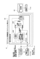
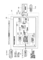
- the controller 21 will be described with reference to FIG.
- the in-vehicle gyro signal (roll rate, pitch rate) which is the sensor information of the navigation device 17 and the CAN signal other than the in-vehicle gyro signal (vehicle body speed, wheel speed, front-rear acceleration, lateral acceleration, steering angle, etc.) And are shown separately.
- the vehicle-mounted gyro signal is input to the controller 21 from the gyro sensor 17A of the navigation device 17.
- any signal is input to the controller 21 via the CAN 16 constituting the in-vehicle LAN.
- the estimated pitch rate and roll rate have the advantage of being able to remove noise and the advantage of not causing a delay.
- Directly sensed pitch rate and roll rate have the advantage of good accuracy, but they may carry noise, and if noise is removed by a filter, the phase will shift. Therefore, the control performance of the suspension system can be improved by using both for suspension control according to the application. For example, in ride comfort control where responsiveness is important, an estimated value that does not cause a delay is used, and a sensing value is used for a value exceeding an estimable frequency or when it becomes impossible to estimate due to a fail.
- the controller 21 receives not only the signals of the various sensors 11, 12, 13, 14, 15 mounted on the vehicle 1 but also the signals of the gyro sensor 17A of the navigation device 17.
- the controller 21 outputs a control signal for controlling the damping force of the shock absorbers 7 and 10 to the shock absorbers 7 and 10 based on the received signal.
- the control accuracy can be improved even if the vehicle 1 is not equipped with the sensors dedicated to the shock absorbers 7 and 10.
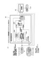
- the smartphone 31 is connected to the CAN 16 which is the in-vehicle LAN.
- the gyro information which is the sensor information of the gyro sensor 31A
- the acceleration information which is the sensor information of the acceleration sensor 31B
- the controller 21 obtains the rotational angular velocity in the roll direction and the rotational angular velocity in the pitch direction of the vehicle 1 as the rotational motion of the vehicle from the information of the gyro sensor 31A of the smartphone 31.
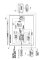
- the vertical movement estimation unit 22C is input from the rotational movement calculation unit 42. And the road surface displacement from the outside world recognition sensor of the outside world recognition device 41 are input.
- the vertical motion estimation unit 22C has a spring speed, a piston speed, and a piston displacement that are state values of the vehicle 1 based on a correction value that is an input value and a wheel speed, a pitch rate, and a road surface displacement that are caused by vertical fluctuations that are observed values. , Roll rate, pitch rate is estimated.
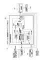
- FIG. 5 shows a fourth embodiment.
- the headlight system is used as an in-vehicle device other than the variable damping force type shock absorber.
- the same components as those in the first embodiment and the third embodiment described above are designated by the same reference numerals, and the description thereof will be omitted.
- the fourth embodiment estimates the state of the vehicle 1 using the information (piston displacement) of the vehicle height sensor 51 of the headlight system as described above, and the basic operation thereof is the first embodiment described above.
- the vehicle height sensor 51 of the headlight system is used as the sensor of the vehicle-mounted device other than the shock absorbers 7 and 10. Therefore, the information (piston displacement information) of the vehicle height sensor 51 of the system (headlight system) other than the shock absorbers 7 and 10 can be used for the state estimation of the vehicle 1 as the observed value, and the state estimation of the vehicle 1 can be used. The accuracy of the can be improved.
- the traveling state information of the vehicle includes at least wheel speed information
- the vehicle control device obtains the vertical movement of the vehicle from the wheel speed information, and the vehicle's vertical motion is obtained.
- the state of the vehicle is estimated from the vertical movement and the rotational movement of the vehicle.
- the state of the vehicle is estimated based on the running state information of the vehicle including the rotational motion (for example, roll rate, pitch rate, etc.) of the vehicle obtained from the information of the gyro sensor and the wheel speed information. be able to.
- the vehicle control device obtains at least one of the rotation angular velocity in the roll direction and the rotation angular velocity in the pitch direction of the vehicle as the rotational motion of the vehicle from the information of the gyro sensor.
- the vertical acceleration on the spring of the vehicle is obtained from an acceleration sensor mounted on an in-vehicle device other than the variable damping force shock absorber, and the rotational motion of the vehicle, the vertical acceleration on the spring, and the running state information of the vehicle are obtained.
- the state of the vehicle is estimated based on the above.
Landscapes
- Engineering & Computer Science (AREA)
- Mechanical Engineering (AREA)
- Vehicle Body Suspensions (AREA)
Priority Applications (5)
| Application Number | Priority Date | Filing Date | Title |
|---|---|---|---|
| JP2022535336A JP7402982B2 (ja) | 2020-07-08 | 2021-07-06 | 車両制御装置およびサスペンションシステム |
| KR1020227038118A KR102766848B1 (ko) | 2020-07-08 | 2021-07-06 | 차량 제어 장치 및 서스펜션 시스템 |
| US18/014,253 US12434529B2 (en) | 2020-07-08 | 2021-07-06 | Vehicle control apparatus and suspension system |
| DE112021003647.5T DE112021003647T5 (de) | 2020-07-08 | 2021-07-06 | Fahrzeugsteuervorrichtung und Aufhängungssystem |
| CN202180048503.4A CN115812043A (zh) | 2020-07-08 | 2021-07-06 | 车辆控制装置和悬架系统 |
Applications Claiming Priority (2)
| Application Number | Priority Date | Filing Date | Title |
|---|---|---|---|
| JP2020-117710 | 2020-07-08 | ||
| JP2020117710 | 2020-07-08 |
Publications (1)
| Publication Number | Publication Date |
|---|---|
| WO2022009869A1 true WO2022009869A1 (ja) | 2022-01-13 |
Family
ID=79553165
Family Applications (1)
| Application Number | Title | Priority Date | Filing Date |
|---|---|---|---|
| PCT/JP2021/025422 Ceased WO2022009869A1 (ja) | 2020-07-08 | 2021-07-06 | 車両制御装置およびサスペンションシステム |
Country Status (6)
| Country | Link |
|---|---|
| US (1) | US12434529B2 (enExample) |
| JP (1) | JP7402982B2 (enExample) |
| KR (1) | KR102766848B1 (enExample) |
| CN (1) | CN115812043A (enExample) |
| DE (1) | DE112021003647T5 (enExample) |
| WO (1) | WO2022009869A1 (enExample) |
Families Citing this family (2)
| Publication number | Priority date | Publication date | Assignee | Title |
|---|---|---|---|---|
| JP7059341B1 (ja) * | 2020-11-26 | 2022-04-25 | 日立Astemo株式会社 | サスペンション制御装置、車両およびサスペンション制御方法 |
| KR102896678B1 (ko) | 2024-02-14 | 2025-12-05 | 서울대학교산학협력단 | 선형 2차 가우시안을 통한 농업 트랙터용 반능동 캐빈 현가장치 최적 제어 시스템 |
Citations (3)
| Publication number | Priority date | Publication date | Assignee | Title |
|---|---|---|---|---|
| JP2010083329A (ja) * | 2008-09-30 | 2010-04-15 | Hitachi Automotive Systems Ltd | サスペンション制御装置 |
| WO2018105399A1 (ja) * | 2016-12-09 | 2018-06-14 | 日立オートモティブシステムズ株式会社 | 車両運動状態推定装置 |
| WO2019077972A1 (ja) * | 2017-10-19 | 2019-04-25 | 日本精工株式会社 | サスペンション操作システム及びサスペンション操作端末 |
Family Cites Families (29)
| Publication number | Priority date | Publication date | Assignee | Title |
|---|---|---|---|---|
| JP4640224B2 (ja) * | 2006-03-15 | 2011-03-02 | 日産自動車株式会社 | 車両走行路の湾曲傾向検出装置およびこれを用いた車両の動作応答制御装置 |
| US8322728B2 (en) * | 2007-09-28 | 2012-12-04 | Hitachi, Ltd. | Suspension control apparatus |
| JP6026207B2 (ja) * | 2012-09-28 | 2016-11-16 | 日立オートモティブシステムズ株式会社 | サスペンション制御装置 |
| US9248794B2 (en) * | 2013-08-26 | 2016-02-02 | Intel Corporation | Configuring user customizable operational features of a vehicle |
| SE540723C2 (sv) * | 2013-11-29 | 2018-10-23 | Bae Systems Haegglunds Ab | Nigningsreducerande fjädringslås för motorfordon |
| US10128890B2 (en) * | 2014-09-09 | 2018-11-13 | Ppip Llc | Privacy and security systems and methods of use |
| US20160121823A1 (en) * | 2014-10-31 | 2016-05-05 | American Axle & Manufacturing, Inc. | Controlling Automotive Vehicle Powertrain, Drivetrain Suspension Components and Accessories Using Portable Personal Electronic Telecommunication Devices |
| US10197999B2 (en) * | 2015-10-16 | 2019-02-05 | Lemmings, Llc | Robotic golf caddy |
| CN109715421B (zh) * | 2016-09-28 | 2022-05-13 | 日立安斯泰莫株式会社 | 悬架控制装置 |
| WO2018096688A1 (ja) * | 2016-11-28 | 2018-05-31 | 本田技研工業株式会社 | 運転支援装置、運転支援システム、プログラム及び運転支援装置の制御方法 |
| JP6286091B1 (ja) * | 2017-05-30 | 2018-02-28 | 株式会社ショーワ | 車両状態推定装置、制御装置、サスペンション制御装置、及びサスペンション装置。 |
| JP7028649B2 (ja) | 2018-01-10 | 2022-03-02 | 日立Astemo株式会社 | 車両、車両運動状態推定装置および車両運動状態推定方法 |
| CA3035661A1 (en) * | 2018-03-05 | 2019-09-05 | Thunder Heart Performance Corp. | Motorcycle suspension system with integrated ride height sensor |
| JP6753911B2 (ja) * | 2018-11-06 | 2020-09-09 | 本田技研工業株式会社 | 減衰力可変ダンパの制御装置 |
| US11168163B2 (en) | 2019-01-25 | 2021-11-09 | Sk Innovation Co., Ltd. | Ethylene-(meth)acrylic acid copolymer and water-dispersive composition including the same |
| EP3918222A1 (en) * | 2019-01-30 | 2021-12-08 | Driv Automotive Inc. | Suspension having electrically-controllable material |
| KR102587419B1 (ko) * | 2019-03-27 | 2023-10-10 | 히다치 아스테모 가부시키가이샤 | 서스펜션 제어 장치 |
| US11954736B1 (en) * | 2019-08-28 | 2024-04-09 | State Farm Mutual Automobile Insurance Company | Systems and methods for generating mobility insurance products using ride-sharing telematics data |
| JP6810779B1 (ja) * | 2019-09-26 | 2021-01-06 | 株式会社ショーワ | 状態量算出装置、制御装置および車両 |
| JP6679801B1 (ja) * | 2019-12-06 | 2020-04-15 | 株式会社ショーワ | 保舵判定装置、ステアリング制御装置、及びステアリング装置 |
| US20210309063A1 (en) * | 2020-04-02 | 2021-10-07 | Fox Factory, Inc. | Vehicle suspension management via an in-vehicle infotainment (ivi) system |
| US11396299B2 (en) * | 2020-04-24 | 2022-07-26 | Dr. Ing. H.C. F. Porsche Aktiengesellschaft | Video processing for vehicle ride incorporating biometric data |
| GB2597460B (en) * | 2020-07-21 | 2023-03-29 | Jaguar Land Rover Ltd | Vehicle active suspension control system and method |
| GB2597457B (en) * | 2020-07-21 | 2023-02-01 | Jaguar Land Rover Ltd | Vehicle active suspension control system and method |
| GB2597452B (en) * | 2020-07-21 | 2023-05-17 | Jaguar Land Rover Ltd | Vehicle active suspension control system and method |
| GB2597458B (en) * | 2020-07-21 | 2023-07-26 | Jaguar Land Rover Ltd | Vehicle active suspension control system and method |
| GB2597456B (en) * | 2020-07-21 | 2022-11-02 | Jaguar Land Rover Ltd | Vehicle active suspension control system and method |
| US11993122B1 (en) * | 2022-02-14 | 2024-05-28 | Zoox, Inc | Updating vehicle models for improved suspension control |
| US12434530B2 (en) * | 2023-08-31 | 2025-10-07 | Ford Technologies, Llc | Methods and apparatus to identify ride height sensor discrepancies |
-
2021
- 2021-07-06 JP JP2022535336A patent/JP7402982B2/ja active Active
- 2021-07-06 DE DE112021003647.5T patent/DE112021003647T5/de active Pending
- 2021-07-06 KR KR1020227038118A patent/KR102766848B1/ko active Active
- 2021-07-06 CN CN202180048503.4A patent/CN115812043A/zh active Pending
- 2021-07-06 WO PCT/JP2021/025422 patent/WO2022009869A1/ja not_active Ceased
- 2021-07-06 US US18/014,253 patent/US12434529B2/en active Active
Patent Citations (3)
| Publication number | Priority date | Publication date | Assignee | Title |
|---|---|---|---|---|
| JP2010083329A (ja) * | 2008-09-30 | 2010-04-15 | Hitachi Automotive Systems Ltd | サスペンション制御装置 |
| WO2018105399A1 (ja) * | 2016-12-09 | 2018-06-14 | 日立オートモティブシステムズ株式会社 | 車両運動状態推定装置 |
| WO2019077972A1 (ja) * | 2017-10-19 | 2019-04-25 | 日本精工株式会社 | サスペンション操作システム及びサスペンション操作端末 |
Also Published As
| Publication number | Publication date |
|---|---|
| JPWO2022009869A1 (enExample) | 2022-01-13 |
| US12434529B2 (en) | 2025-10-07 |
| KR102766848B1 (ko) | 2025-02-11 |
| JP7402982B2 (ja) | 2023-12-21 |
| KR20220161462A (ko) | 2022-12-06 |
| US20230271471A1 (en) | 2023-08-31 |
| DE112021003647T5 (de) | 2023-06-29 |
| CN115812043A (zh) | 2023-03-17 |
Similar Documents
| Publication | Publication Date | Title |
|---|---|---|
| JP5934470B2 (ja) | サスペンション装置 | |
| JP7186282B2 (ja) | サスペンション制御装置 | |
| JP7432446B2 (ja) | 車両制御装置 | |
| JP7548341B2 (ja) | 車両状態量推定装置 | |
| JP7402982B2 (ja) | 車両制御装置およびサスペンションシステム | |
| CN111284287B (zh) | 主动式悬架控制单元及方法 | |
| WO2022024758A1 (ja) | 制御装置 | |
| JP4821766B2 (ja) | 車両用サスペンションシステム | |
| JP2013049394A (ja) | サスペンション制御装置 | |
| US20250128562A1 (en) | Vehicle control device and vehicle control system | |
| JP2013241075A (ja) | サスペンション制御装置 | |
| JP2015083469A (ja) | サスペンション装置 | |
| WO2022112452A1 (en) | Active suspension control on repeating surface undulations | |
| KR100693149B1 (ko) | 차량의 반능동 현가장치 | |
| AU2023263549B2 (en) | Roll control system and vehicle | |
| JP5104594B2 (ja) | 車両制御装置 | |
| JP2009137342A (ja) | 減衰力可変ダンパの制御装置 | |
| JP2009226985A (ja) | 車体姿勢制御装置 | |
| WO2024024216A1 (ja) | 緩衝器 | |
| JP2009173232A (ja) | 車両の乗員姿勢制御装置 | |
| JP2005035486A (ja) | 車両懸架装置 | |
| KR100397264B1 (ko) | 전자 제어 현가 장치 | |
| WO2025047931A1 (ja) | 車両制御装置 | |
| KR100648811B1 (ko) | 액티브 지오메트리 컨트롤드 서스펜션 시스템의 제어 방법 | |
| WO2024195493A1 (ja) | 車両挙動推定方法および車両挙動推定装置 |
Legal Events
| Date | Code | Title | Description |
|---|---|---|---|
| 121 | Ep: the epo has been informed by wipo that ep was designated in this application |
Ref document number: 21837479 Country of ref document: EP Kind code of ref document: A1 |
|
| ENP | Entry into the national phase |
Ref document number: 2022535336 Country of ref document: JP Kind code of ref document: A |
|
| ENP | Entry into the national phase |
Ref document number: 20227038118 Country of ref document: KR Kind code of ref document: A |
|
| 122 | Ep: pct application non-entry in european phase |
Ref document number: 21837479 Country of ref document: EP Kind code of ref document: A1 |
|
| WWG | Wipo information: grant in national office |
Ref document number: 18014253 Country of ref document: US |