以下、実施形態による車両制御装置およびサスペンションシステムを、車両としての自動車(より具体的には、4輪自動車)に用いる場合を例に挙げ、添付図面を参照しつつ説明する。
Hereinafter, the case where the vehicle control device and the suspension system according to the embodiment are used for an automobile as a vehicle (more specifically, a four-wheeled automobile) will be described as an example, with reference to the attached drawings.
図1および図2は、第1の実施形態を示している。図1において、自動車である車両1のボディを構成する車体2の下側には、例えば左右の前輪3と左右の後輪4(一方のみ図示)との合計4個の車輪3,4が設けられている。左右の前輪3と車体2との間には、それぞれ前輪側のサスペンション5,5(以下、前輪サスペンション5という)が介装して設けられている。前輪サスペンション5は、懸架ばね6(以下、ばね6という)、および、ばね6と並列に設けられた減衰力調整式緩衝器7(以下、緩衝器7という)を備えている。
1 and 2 show the first embodiment. In FIG. 1, a total of four wheels 3, 4 including left and right front wheels 3 and left and right rear wheels 4 (only one of which is shown) are provided on the lower side of the vehicle body 2 constituting the body of the vehicle 1, which is an automobile. Has been done. Suspensions 5 and 5 on the front wheel side (hereinafter referred to as front wheel suspension 5) are interposed between the left and right front wheels 3 and the vehicle body 2, respectively. The front wheel suspension 5 includes a suspension spring 6 (hereinafter referred to as a spring 6) and a damping force adjusting shock absorber 7 (hereinafter referred to as a shock absorber 7) provided in parallel with the spring 6.
左右の後輪4と車体2との間には、それぞれ後輪側のサスペンション8,8(以下、後輪サスペンション8という)が介装して設けられている。後輪サスペンション8は、懸架ばね9(以下、ばね9という)、および、ばね9と並列に設けられた減衰力調整式緩衝器10(以下、緩衝器10という)を備えている。緩衝器7,10は、例えば、減衰力の調整が可能な油圧式のシリンダ装置(減衰力可変式ショックアブソーバ)となるセミアクティブダンパにより構成されている。即ち、車両1は、減衰力可変式ショックアブソーバを用いたセミアクティブサスペンションシステムが搭載されている。
Suspensions 8 and 8 on the rear wheel side (hereinafter referred to as rear wheel suspension 8) are provided between the left and right rear wheels 4 and the vehicle body 2, respectively. The rear wheel suspension 8 includes a suspension spring 9 (hereinafter referred to as a spring 9) and a damping force adjusting shock absorber 10 (hereinafter referred to as a shock absorber 10) provided in parallel with the spring 9. The shock absorbers 7 and 10 are composed of, for example, a semi-active damper which is a hydraulic cylinder device (variable damping force shock absorber) whose damping force can be adjusted. That is, the vehicle 1 is equipped with a semi-active suspension system using a variable damping force shock absorber.
ここで、緩衝器7,10は、車両1の車体2と車輪3,4との間に設けられた減衰力可変型の減衰力発生装置(減衰力可変型緩衝器)である。緩衝器7,10は、車両1の姿勢を制御する車体姿勢制御装置に相当する。即ち、緩衝器7,10は、後述するコントローラ21によって発生減衰力の特性(減衰力特性)が可変に制御される。このために、緩衝器7,10には、減衰力特性をハードな特性(硬特性)からソフトな特性(軟特性)に連続的(ないし多段階)に調整するため、減衰力調整バルブおよびソレノイド等からなるアクチュエータ(図示せず)が付設されている。緩衝器7,10は、コントローラ21からアクチュエータへ供給される指令電流(制御信号)に応じて減衰力特性が可変に調整される。
Here, the shock absorbers 7 and 10 are damping force generators (variable damping force type shock absorbers) provided between the vehicle body 2 of the vehicle 1 and the wheels 3 and 4. The shock absorbers 7 and 10 correspond to a vehicle body attitude control device that controls the attitude of the vehicle 1. That is, in the shock absorbers 7 and 10, the characteristic of the generated damping force (damping force characteristic) is variably controlled by the controller 21 described later. For this purpose, the shock absorbers 7 and 10 have a damping force adjusting valve and a solenoid in order to continuously (or multi-step) adjust the damping force characteristics from hard characteristics (hard characteristics) to soft characteristics (soft characteristics). An actuator (not shown) consisting of the above is attached. The damping force characteristics of the shock absorbers 7 and 10 are variably adjusted according to the command current (control signal) supplied from the controller 21 to the actuator.
なお、減衰力調整バルブとしては、減衰力発生バルブのパイロット圧を制御する圧力制御方式や通路面積を制御する流量制御方式等、従来から知られている構造を用いることができる。また、緩衝器7,10は、減衰力を連続的(ないし多段階)に調整できればよく、例えば、空圧ダンパや電磁ダンパ、電気粘性流体ダンパ、磁性流体ダンパであってもよい。また、緩衝器7,10は、エアばね(空気ばね)を用いたエアダンパ(エアサス)、前後左右の油圧シリンダを配管で接続した油圧ダンパ(車高調整装置)、左右の車輪の動きに対して力を与えるスタビライザ等であってもよい。さらに、緩衝器7,10は、推力を発生できる液圧式アクチュエータ、電動式アクチュエータまたは気圧式アクチュエータにより構成されるフルアクティブダンパでもよい。即ち、車両1にフルアクティブダンパを用いたフルアクティブサスペンションシステムを搭載してもよい。
As the damping force adjusting valve, a conventionally known structure such as a pressure control method for controlling the pilot pressure of the damping force generating valve and a flow rate control method for controlling the passage area can be used. Further, the shock absorbers 7 and 10 may be a pneumatic damper, an electromagnetic damper, an electrorheological fluid damper, or a magnetic fluid damper, as long as the damping force can be adjusted continuously (or in multiple stages). Further, the shock absorbers 7 and 10 are for an air damper (air suspension) using an air spring (air spring), a hydraulic damper (vehicle height adjusting device) in which front, rear, left and right hydraulic cylinders are connected by pipes, and movement of left and right wheels. It may be a stabilizer or the like that gives power. Further, the shock absorbers 7 and 10 may be a fully active damper composed of a hydraulic actuator, an electric actuator or a barometric actuator capable of generating thrust. That is, the vehicle 1 may be equipped with a fully active suspension system using a fully active damper.
次に、車両1の状態を検出する各種のセンサ11,12,13,14,15について説明する。
Next, various sensors 11, 12, 13, 14, and 15 for detecting the state of the vehicle 1 will be described.
図1に示すように、車両1には、車速センサ11、車輪速センサ12、前後加速度センサ13、左右加速度センサ14、および、舵角センサ15が設けられている。これらの各センサ11,12,13,14,15は、車両1に一般的に搭載されているセンサ、より具体的には、車両1の制動、駆動、操舵の制御に主として用いられるセンサである。
As shown in FIG. 1, the vehicle 1 is provided with a vehicle speed sensor 11, a wheel speed sensor 12, a front-rear acceleration sensor 13, a left-right acceleration sensor 14, and a steering angle sensor 15. Each of these sensors 11, 12, 13, 14, and 15 is a sensor generally mounted on the vehicle 1, more specifically, a sensor mainly used for controlling braking, driving, and steering of the vehicle 1. ..
車速センサ11は、例えば車両1に搭載された変速装置の出力軸(図示せず)に設けられている。車速センサ11は、車両1(車体2)の速度である車体速度を検出する。車速センサ11の検出情報(車体速度に対応する信号)は、例えば車内LAN通信であるCAN16(後述の図2)を介して車両に搭載された各種のコントローラ(ECU)に出力される。図示は省略するが、車速センサ11の情報(車体速度)は、CAN16を介して、車両1の制駆動システム(制動システム、駆動システム)のコントローラ(制駆動用ECU、制動用ECU、駆動用ECU)、車両1の操舵システムのコントローラ(操舵用ECU)等に出力される。また、後述の図2に示すように、車速センサ11の情報(車体速度)は、CAN16を介して、車両1のサスペンションシステムのコントローラ21(サスペンション用ECU)に出力される。
The vehicle speed sensor 11 is provided, for example, on the output shaft (not shown) of the transmission mounted on the vehicle 1. The vehicle speed sensor 11 detects the vehicle body speed, which is the speed of the vehicle 1 (vehicle body 2). The detection information (signal corresponding to the vehicle body speed) of the vehicle speed sensor 11 is output to various controllers (ECUs) mounted on the vehicle via, for example, CAN 16 (FIG. 2 described later) which is an in-vehicle LAN communication. Although not shown, the information (vehicle body speed) of the vehicle speed sensor 11 is transmitted to the controller (control drive ECU, braking ECU, drive ECU) of the vehicle 1 control drive system (braking system, drive system) via the CAN 16. ), It is output to the controller (steering ECU) of the steering system of the vehicle 1. Further, as shown in FIG. 2 described later, the information (vehicle body speed) of the vehicle speed sensor 11 is output to the controller 21 (suspension ECU) of the suspension system of the vehicle 1 via the CAN 16.
車輪速センサ12は、例えば車輪3,4を支持する車輪支持用ハブユニットに設けられている。車輪速センサ12は、それぞれの車輪3,4に対応して設けられている。車輪速センサ12は、車輪3,4の回転速度を検出する。車輪速センサ12の検出情報(車輪速に対応する信号)は、例えばCAN16を介して各種のコントローラ(ECU)に出力される。図示は省略するが、車輪速センサ12の情報(車輪速)は、CAN16を介して、車両1の制駆動システム(制動システム、駆動システム)のコントローラ(制駆動用ECU、制動用ECU、駆動用ECU)等に出力される。また、後述の図2に示すように、車輪速センサ12の情報(車輪速)は、CAN16を介して、車両1のサスペンションシステムのコントローラ21(サスペンション用ECU)に出力される。なお、車速センサ11を省略すると共に、車輪速センサ12の車輪速から車体速度を取得する構成としてもよい。
The wheel speed sensor 12 is provided in, for example, a wheel support hub unit that supports the wheels 3 and 4. The wheel speed sensor 12 is provided corresponding to each of the wheels 3 and 4. The wheel speed sensor 12 detects the rotational speeds of the wheels 3 and 4. The detection information (signal corresponding to the wheel speed) of the wheel speed sensor 12 is output to various controllers (ECUs) via, for example, CAN 16. Although not shown, the information (wheel speed) of the wheel speed sensor 12 is transmitted to the controller (brake control ECU, braking ECU, drive) of the control drive system (braking system, drive system) of the vehicle 1 via the CAN 16. It is output to the ECU) and so on. Further, as shown in FIG. 2 described later, the information (wheel speed) of the wheel speed sensor 12 is output to the controller 21 (suspension ECU) of the suspension system of the vehicle 1 via the CAN 16. The vehicle speed sensor 11 may be omitted, and the vehicle body speed may be acquired from the wheel speed of the wheel speed sensor 12.
前後加速度センサ13および左右加速度センサ14は、例えば車両1のばね上側となる車体2に設けられている。前後加速度センサ13は、車両1(車体2)の前後方向の加速度(減速度、加速度)を検出する。左右加速度センサ14は、車両1(車体2)の左右方向の加速度(横加速度)を検出する。前後加速度センサ13の検出データ(前後加速度に対応する信号)および左右加速度センサ14の検出データ(左右加速度に対応する信号)は、例えばCAN16を介して各種のコントローラ(ECU)に出力される。図示は省略するが、前後加速度センサ13の情報(前後加速度)および左右加速度センサ14の情報(左右加速度)は、CAN16を介して、車両1の制駆動システム(制動システム、駆動システム)のコントローラ(制駆動用ECU、制動用ECU、駆動用ECU)等に出力される。また、後述の図2に示すように、前後加速度センサ13の情報(前後加速度)および左右加速度センサ14の情報(左右加速度)は、CAN16を介して、車両1のサスペンションシステムのコントローラ21(サスペンション用ECU)に出力される。
The front-rear acceleration sensor 13 and the left-right acceleration sensor 14 are provided on the vehicle body 2 which is above the spring of the vehicle 1, for example. The front-rear acceleration sensor 13 detects the acceleration (deceleration, acceleration) in the front-rear direction of the vehicle 1 (vehicle body 2). The left-right acceleration sensor 14 detects the left-right acceleration (lateral acceleration) of the vehicle 1 (vehicle body 2). The detection data of the front-back acceleration sensor 13 (signal corresponding to the front-back acceleration) and the detection data of the left-right acceleration sensor 14 (signal corresponding to the left-right acceleration) are output to various controllers (ECUs) via, for example, CAN 16. Although not shown, the information of the front-rear acceleration sensor 13 (front-back acceleration) and the information of the left-right acceleration sensor 14 (left-right acceleration) are transmitted to the controller of the control drive system (braking system, drive system) of the vehicle 1 via the CAN 16. It is output to the control drive ECU, braking ECU, drive ECU) and the like. Further, as shown in FIG. 2 described later, the information of the front-rear acceleration sensor 13 (front-back acceleration) and the information of the left-right acceleration sensor 14 (left-right acceleration) are transmitted to the controller 21 (for suspension) of the suspension system of the vehicle 1 via the CAN 16. It is output to the ECU).
舵角センサ15は、例えば車両1の操舵装置(図示せず)に設けられている。舵角センサ15は、車両1を運転するドライバ(運転者)のステアリング操作によって生じる操舵角(回転角)または車輪(前輪3)の舵角を検出する。舵角センサ15の検出データ(操舵角に対応する信号)は、例えばCAN16を介して各種のコントローラ(ECU)に出力される。図示は省略するが、舵角センサ15の情報(操舵角)は、CAN16を介して、車両1の操舵システムのコントローラ(操舵用ECU)等に出力される。また、後述の図2に示すように、舵角センサ15の情報(操舵角)は、CAN16を介して、車両1のサスペンションシステムのコントローラ21(サスペンション用ECU)に出力される。
The steering angle sensor 15 is provided, for example, in the steering device (not shown) of the vehicle 1. The steering angle sensor 15 detects the steering angle (rotation angle) or the steering angle of the wheels (front wheels 3) generated by the steering operation of the driver (driver) who drives the vehicle 1. The detection data (signal corresponding to the steering angle) of the steering angle sensor 15 is output to various controllers (ECUs) via, for example, CAN 16. Although not shown, the information (steering angle) of the steering angle sensor 15 is output to the controller (steering ECU) of the steering system of the vehicle 1 via the CAN 16. Further, as shown in FIG. 2 to be described later, the information (steering angle) of the steering angle sensor 15 is output to the controller 21 (suspension ECU) of the suspension system of the vehicle 1 via the CAN 16.
ここで、各センサ11,12,13,14,15は、サスペンションシステム(緩衝器7,10)専用のセンサではない。即ち、各センサ11,12,13,14,15は、緩衝器7,10を制御する以外の目的で車両に搭載されたセンサ、換言すれば、緩衝器7,10以外の車載装置を主として制御するために車両に搭載されたセンサである。具体的には、センサ11,12,13,14,15は、車両1を駆動および/または制動するエンジン、走行用駆動モータ、油圧ブレーキ、電動ブレーキ等の車両制駆動装置(駆動装置、制動装置)、車両1を操舵する電動パワーステアリング装置等の操舵装置を主として制御するためのセンサとして車両1に搭載されている。そして、車両制駆動装置(駆動装置、制動装置)および操舵装置は、車両1を制御(車両1の挙動を制御)するための車載装置(車載システム)に対応する。
Here, the sensors 11, 12, 13, 14, and 15 are not dedicated sensors for the suspension system (buffers 7, 10). That is, each of the sensors 11, 12, 13, 14, and 15 mainly controls sensors mounted on the vehicle for purposes other than controlling the shock absorbers 7, 10, in other words, in-vehicle devices other than the shock absorbers 7, 10. It is a sensor mounted on the vehicle to do so. Specifically, the sensors 11, 12, 13, 14, 15 are vehicle control drive devices (drive device, braking device) such as an engine for driving and / or braking the vehicle 1, a traveling drive motor, a hydraulic brake, and an electric brake. ), It is mounted on the vehicle 1 as a sensor for mainly controlling a steering device such as an electric power steering device that steers the vehicle 1. The vehicle control drive device (drive device, braking device) and steering device correspond to an in-vehicle device (vehicle-mounted system) for controlling the vehicle 1 (controlling the behavior of the vehicle 1).
この場合、車速センサ11、車輪速センサ12、前後加速度センサ13および左右加速度センサ14は、車両1の駆動、制動を制御するための車両制駆動システム用のセンサである。即ち、車速センサ11、車輪速センサ12、前後加速度センサ13および左右加速度センサ14は、車両制駆動装置(エンジン、走行用駆動モータ、油圧ブレーキ、電動ブレーキ等)を主として制御するために用いられるセンサである。舵角センサ15は、車両1の操舵を制御するための操舵システム用のセンサである。即ち、舵角センサ15は、操舵装置(電動パワーステアリング装置)を主として制御するために用いられるセンサである。いずれにしても、各センサ11,12,13,14,15は、車両1に搭載されたコントローラ21等の各種のECUおよび各種のセンサを含む多数の電子機器の間で車載向けの多重通信を行うシリアル通信部としてのCAN16に接続されている。
In this case, the vehicle speed sensor 11, the wheel speed sensor 12, the front-rear acceleration sensor 13, and the left-right acceleration sensor 14 are sensors for a vehicle control drive system for controlling the drive and braking of the vehicle 1. That is, the vehicle speed sensor 11, the wheel speed sensor 12, the front-rear acceleration sensor 13, and the left-right acceleration sensor 14 are sensors mainly used to control the vehicle control drive device (engine, driving drive motor, hydraulic brake, electric brake, etc.). Is. The steering angle sensor 15 is a sensor for a steering system for controlling the steering of the vehicle 1. That is, the steering angle sensor 15 is a sensor mainly used to control the steering device (electric power steering device). In any case, each of the sensors 11, 12, 13, 14, and 15 performs multiplex communication for automobiles between various ECUs such as the controller 21 mounted on the vehicle 1 and a large number of electronic devices including various sensors. It is connected to CAN 16 as a serial communication unit to perform.
次に、緩衝器7,10を制御するコントローラ21について説明する。
Next, the controller 21 that controls the shock absorbers 7 and 10 will be described.
車両制御装置としてのコントローラ21は、マイクロコンピュータ、電源回路、駆動回路を含んで構成されており、ECU(Electronic Control Unit)とも呼ばれている。コントローラ21は、サスペンションシステム用のコントローラ(制御装置)、即ち、サスペンション用ECU(緩衝器用ECU)である。コントローラ21は、緩衝器7,10専用以外のセンサ11,12,13,14,15等により検出されるセンサ情報に基づいて、緩衝器7,10を制御(減衰力を調整)する。この場合、コントローラ21は、センサ情報に基づいて車両1の状態を推定し、推定された車両1の状態に応じて緩衝器7,10を制御する。
The controller 21 as a vehicle control device includes a microcomputer, a power supply circuit, and a drive circuit, and is also called an ECU (Electronic Control Unit). The controller 21 is a controller (control device) for the suspension system, that is, an ECU for suspension (ECU for shock absorber). The controller 21 controls the shock absorbers 7 and 10 (adjusts the damping force) based on the sensor information detected by the sensors 11, 12, 13, 14, 15 and the like other than the shock absorbers 7 and 10. In this case, the controller 21 estimates the state of the vehicle 1 based on the sensor information, and controls the shock absorbers 7 and 10 according to the estimated state of the vehicle 1.
図2に示すように、コントローラ21は、CAN16に接続されている。これにより、コントローラ21には、CAN16を介して、車速センサ11の信号、車輪速センサ12の信号、前後加速度センサ13の信号、左右加速度センサ14の信号、舵角センサ15の信号がCAN信号として入力される。また、コントローラ21には、後述するように、CAN16を介して、ナビゲーション装置17のジャイロセンサ17Aの信号が車載ジャイロ信号として入力される。一方、コントローラ21の出力側は、制御ダンパである緩衝器7,10に接続されている。コントローラ21は、緩衝器7,10のアクチュエータ(例えば、減衰力調整バルブの開弁圧を調整するソレノイド)に制御信号(指令電流)を出力する。
As shown in FIG. 2, the controller 21 is connected to the CAN 16. As a result, the signal of the vehicle speed sensor 11, the signal of the wheel speed sensor 12, the signal of the front-rear acceleration sensor 13, the signal of the left-right acceleration sensor 14, and the signal of the steering angle sensor 15 are used as CAN signals in the controller 21 via the CAN 16. Entered. Further, as will be described later, the signal of the gyro sensor 17A of the navigation device 17 is input to the controller 21 as an in-vehicle gyro signal via the CAN 16. On the other hand, the output side of the controller 21 is connected to the shock absorbers 7 and 10 which are control dampers. The controller 21 outputs a control signal (command current) to the actuators of the shock absorbers 7 and 10 (for example, the solenoid that adjusts the valve opening pressure of the damping force adjusting valve).
コントローラ21は、CPU(演算処理装置)等の演算処理を行うコントロール部21A(図1参照)、および、ROM、RAM、不揮発性メモリ等のメモリからなる記憶部21B(図1参照)を備えている。記憶部21Bには、各センサ11,12,13,14,15等の情報(入力信号)から車両状態(車両運動、車両挙動)を演算(推定)する処理プログラム、車両の状態(車両運動、車両挙動)から緩衝器7,10で発生すべき減衰力を演算する処理プログラム、発生すべき減衰力に対応する制御信号を出力する処理プログラム等が格納されている。
The controller 21 includes a control unit 21A (see FIG. 1) that performs arithmetic processing such as a CPU (arithmetic processing unit), and a storage unit 21B (see FIG. 1) composed of memories such as ROM, RAM, and non-volatile memory. There is. The storage unit 21B has a processing program for calculating (estimating) the vehicle state (vehicle motion, vehicle behavior) from information (input signals) such as sensors 11, 12, 13, 14, 15, and the vehicle state (vehicle motion, vehicle motion). A processing program for calculating the damping force to be generated by the shock absorbers 7 and 10 from the vehicle behavior), a processing program for outputting a control signal corresponding to the damping force to be generated, and the like are stored.
緩衝器7,10の減衰力を演算する制御則(乗り心地の制御則、操縦安定性の制御則)としては、例えば、スカイフック制御則、LQG制御則またはH∞制御則等を用いることができる。コントローラ21は、例えば、ばね上となる車体2の運動(挙動)を緩衝器7,10の減衰力によって減速させる場合は、緩衝器7,10の減衰力を大きくし、ばね上となる車体2の運動(挙動)を緩衝器7,10の減衰力によって加速させる場合は、緩衝器7,10の減衰力を抑制する。減衰力可変ダンパである緩衝器7,10は、減衰力を可変させて適切に各車輪3,4の上下動を減衰させることにより、車体2の振動を抑制する働きを持っている。
As the control rules (ride comfort control rule, steering stability control rule) for calculating the damping force of the shock absorbers 7 and 10, for example, the skyhook control rule, the LQG control rule, the H∞ control rule, or the like can be used. can. For example, when the controller 21 decelerates the motion (behavior) of the vehicle body 2 on the spring by the damping force of the shock absorbers 7 and 10, the damping force of the shock absorbers 7 and 10 is increased and the vehicle body 2 on the spring is increased. When the motion (behavior) of is accelerated by the damping force of the shock absorbers 7 and 10, the damping force of the shock absorbers 7 and 10 is suppressed. The shock absorbers 7 and 10, which are variable damping force dampers, have a function of suppressing the vibration of the vehicle body 2 by varying the damping force and appropriately damping the vertical movement of each of the wheels 3 and 4.
ところで、車両(自動車)のサスペンションシステムは、車両(自動車)の乗り心地と操縦安定性とを両立させる手段である。セミアクティブサスペンションシステムでは、車体と車輪との間に取付けられた減衰力可変式ショックアブソーバの減衰力を切換えて車体運動を制御することにより、乗り心地と操縦安定性とを向上させる。このようなサスペンションシステムでは、様々なセンサ構成のシステムが考えられている。
By the way, the suspension system of a vehicle (automobile) is a means to achieve both the ride quality of the vehicle (automobile) and the steering stability. In the semi-active suspension system, the riding comfort and steering stability are improved by switching the damping force of the variable damping force shock absorber installed between the vehicle body and the wheels to control the vehicle body motion. In such a suspension system, a system having various sensor configurations is considered.
例えば、従来のサスペンションシステムでは、ばね上加速度センサ、ばね下加速度センサ、車高センサ等の情報と、車内LAN通信(CAN通信)から入手した他システムでセンシングした情報とを用いて、減衰力可変式ショックアブソーバの減衰力を制御する。即ち、「サスペンションシステム専用のセンサ(ばね上加速度センサ、ばね下加速度センサ、車高センサ)の情報」と「他システムでセンシングした情報」とを基に車両状態を推定(算出)し、推定した車両状態に応じて減衰力可変式ショックアブソーバを制御する。このような構成の場合は、センサの数が多い程、車両状態の推定精度が良くなり、乗り心地、操縦安定性を向上できるが、システムコストの増大が避けられない。
For example, in a conventional suspension system, the damping force is variable by using information such as an on-spring acceleration sensor, a under-spring acceleration sensor, and a vehicle height sensor, and information sensed by another system obtained from in-vehicle LAN communication (CAN communication). Controls the damping force of the shock absorber. That is, the vehicle state was estimated (calculated) and estimated based on "information of sensors dedicated to the suspension system (up spring acceleration sensor, unsprung acceleration sensor, vehicle height sensor)" and "information sensed by another system". The variable damping force shock absorber is controlled according to the vehicle condition. In such a configuration, the larger the number of sensors, the better the estimation accuracy of the vehicle state, and the better the riding comfort and steering stability, but the increase in system cost is unavoidable.
これに対して、最も廉価なシステムとして、サスペンションシステムにセンサを持たず、他システムのセンサ情報を用いて車両(車体)の状態を推定し、サスペンションの制御を行うことが考えられる。例えば、前述の特許文献1の技術によれば、車両の制駆動制御システムおよび操舵制御システムから得られるセンサ情報を基に車体の状態推定を行う。この場合に、例えば、オブザーバの一種であるカルマンフィルタを用いて車体の状態推定を行うことが考えられる。しかし、カルマンフィルタの観測値に、車体の上下運動による車輪速度の変動成分、ロールレイト、ピッチレイトと、全て推定値を用いて演算を行う構成とした場合は、観測値の推定精度が悪くなると、車体の状態推定精度も悪くなるおそれがある。
On the other hand, as the cheapest system, it is conceivable that the suspension system does not have a sensor and the state of the vehicle (vehicle body) is estimated using the sensor information of another system to control the suspension. For example, according to the technique of Patent Document 1 described above, the state of the vehicle body is estimated based on the sensor information obtained from the vehicle control drive control system and the steering control system. In this case, for example, it is conceivable to estimate the state of the vehicle body by using a Kalman filter which is a kind of observer. However, if the Kalman filter's observed values are calculated using estimated values such as wheel speed fluctuation components due to vertical movement of the vehicle body, roll rate, and pitch rate, the estimation accuracy of the observed values will deteriorate. The accuracy of vehicle body condition estimation may also deteriorate.
そこで、実施形態では、サスペンションシステム専用のセンサを持たず、車内LAN通信(CAN通信)で入手した情報のみを用いて車両状態を推定する。この場合に、実施形態では、既存の制駆動制御システムおよび操舵制御システムから得られるセンサ情報以外で、かつ、サスペンションシステム外のシステムで得られるセンサ情報を直接、観測値として入力することにより、車両の状態推定精度を向上させる。また、実施形態では、サスペンションシステムの制御で用いる物理量のうち直接センシングできる物理量は、その値を直接制御に用いることもできるし、ノイズ成分が除去された推定値を用いることもできる。このため、「直接センシングした精度のよい値」と「ノイズが取れた値」とを用途に応じて使い分けることにより、制御性能を向上できる。
Therefore, in the embodiment, the vehicle state is estimated using only the information obtained by the in-vehicle LAN communication (CAN communication) without having the sensor dedicated to the suspension system. In this case, in the embodiment, the vehicle is obtained by directly inputting the sensor information obtained by the system other than the suspension system other than the sensor information obtained from the existing control drive control system and the steering control system as the observed value. Improve the accuracy of state estimation. Further, in the embodiment, as the physical quantity that can be directly sensed among the physical quantities used in the control of the suspension system, the value can be used for the direct control, or the estimated value from which the noise component is removed can be used. Therefore, the control performance can be improved by properly using the "directly sensed accurate value" and the "noise-removed value" according to the application.
即ち、実施形態では、サスペンションシステムは、緩衝器7,10と、緩衝器7,10に制御信号を出力するコントローラ21と、車両1に搭載された車輪速センサ12とを備えている。サスペンションシステムは、車輪速センサ12の車輪速情報から車両1の状態を推定し、推定された車両1の状態に応じて緩衝器7,10の減衰力を制御する。この場合、サスペンションシステムは、車両1を制御するためのシステム(例えば、制駆動システム、操舵システム)以外の車載システムのセンサ情報を、緩衝器7,10の制御に用いる。
That is, in the embodiment, the suspension system includes shock absorbers 7 and 10, a controller 21 that outputs a control signal to the shock absorbers 7 and 10, and a wheel speed sensor 12 mounted on the vehicle 1. The suspension system estimates the state of the vehicle 1 from the wheel speed information of the wheel speed sensor 12, and controls the damping force of the shock absorbers 7 and 10 according to the estimated state of the vehicle 1. In this case, the suspension system uses the sensor information of the in-vehicle system other than the system for controlling the vehicle 1 (for example, the control drive system, the steering system) for the control of the shock absorbers 7 and 10.
即ち、第1の実施形態では、サスペンションシステムは、車両1を制御する(車両1の挙動を制御する)ためのシステム以外の車載システムとなるナビゲーションシステム(ナビゲーション装置17)のセンサ情報を、緩衝器7,10の制御に用いる。より具体的には、サスペンションシステムは、ナビゲーションシステム(ナビゲーション装置17)に搭載されたジャイロセンサ17Aのセンサ情報となるジャイロ情報を、車両1の状態推定(カルマンフィルタ)の観測値として用いる。
That is, in the first embodiment, the suspension system uses the sensor information of the navigation system (navigation device 17), which is an in-vehicle system other than the system for controlling the vehicle 1 (controlling the behavior of the vehicle 1), as a shock absorber. Used for control of 7 and 10. More specifically, the suspension system uses the gyro information, which is the sensor information of the gyro sensor 17A mounted on the navigation system (navigation device 17), as the observed value of the state estimation (Kalman filter) of the vehicle 1.
換言すれば、コントローラ21(コントロール部21A)は、車両1に設けられた車輪速センサ12から車両1の状態を推定し、推定された車両1の状態に応じて緩衝器7,10に制御信号を出力する。この場合、コントローラ21は、緩衝器7,10専用以外の車載装置のセンサ情報を、車両1の状態推定に用いる。即ち、コントローラ21は、緩衝器7,10専用以外の車載装置となるナビゲーション装置17のセンサ情報を車両1の状態推定に用いる。より具体的には、コントローラ21は、ナビゲーション装置17に搭載されたジャイロセンサ17Aの情報となるジャイロ情報を、車両1の状態推定(カルマンフィルタ)の観測値として車両1の状態推定に用いる。ジャイロセンサ17Aは、緩衝器7,10専用以外のセンサに相当する。
In other words, the controller 21 (control unit 21A) estimates the state of the vehicle 1 from the wheel speed sensor 12 provided in the vehicle 1, and controls signals to the shock absorbers 7 and 10 according to the estimated state of the vehicle 1. Is output. In this case, the controller 21 uses the sensor information of the in-vehicle device other than the shock absorbers 7 and 10 for estimating the state of the vehicle 1. That is, the controller 21 uses the sensor information of the navigation device 17, which is an in-vehicle device other than the shock absorbers 7 and 10, for estimating the state of the vehicle 1. More specifically, the controller 21 uses the gyro information, which is the information of the gyro sensor 17A mounted on the navigation device 17, for the state estimation of the vehicle 1 as the observed value of the state estimation (Kalman filter) of the vehicle 1. The gyro sensor 17A corresponds to a sensor other than the shock absorbers 7 and 10.
このために、図1に示すように、車両1は、ジャイロセンサ17Aが搭載されたナビゲーション装置17を備えている。ナビゲーション装置17は、車内LANとなるCAN16に接続されている。ジャイロセンサ17Aのセンサ情報となるジャイロ情報は、CAN16を介して、車両1のサスペンションシステムのコントローラ21に出力される。ジャイロセンサ17Aは、車両1(車体2)の前後方向に延びるロール軸、車両1(車体2)の左右方向に延びるピッチ軸、車両1(車体2)の上下方向に延びるヨー軸の3つの軸のうちの少なくともいずれかの軸周りの角速度をジャイロ情報として検出する。
For this purpose, as shown in FIG. 1, the vehicle 1 is provided with a navigation device 17 equipped with a gyro sensor 17A. The navigation device 17 is connected to CAN 16 which is an in-vehicle LAN. The gyro information, which is the sensor information of the gyro sensor 17A, is output to the controller 21 of the suspension system of the vehicle 1 via the CAN 16. The gyro sensor 17A has three axes: a roll axis extending in the front-rear direction of the vehicle 1 (vehicle body 2), a pitch axis extending in the left-right direction of the vehicle 1 (vehicle body 2), and a yaw axis extending in the vertical direction of the vehicle 1 (vehicle body 2). The angular velocity around at least one of these axes is detected as gyro information.
即ち、ジャイロセンサ17Aは、車両1のロール方向の回転角速度となるロールレイトと、車両1のピッチ方向の回転角速度となるピッチレイトと、車両1のヨー方向の回転角速度となるヨーレイトとのうちの少なくとも何れかを検出する。例えば、実施形態では、ジャイロセンサ17Aは、ロールレイトとピッチレイトとを検出する。ジャイロセンサ17Aで検出されたロールレイトとピッチレイトは、CAN16を介してコントローラ21に出力される。
That is, the gyro sensor 17A has a roll rate that is the rotation angular velocity of the vehicle 1 in the roll direction, a pitch rate that is the rotation angular velocity of the vehicle 1 in the pitch direction, and a yaw rate that is the rotation angular velocity of the vehicle 1 in the yaw direction. Detect at least one. For example, in the embodiment, the gyro sensor 17A detects a roll rate and a pitch rate. The roll rate and pitch rate detected by the gyro sensor 17A are output to the controller 21 via the CAN 16.
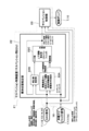
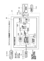
コントローラ21について、図2を参照しつつ説明する。なお、図2では、ナビゲーション装置17のセンサ情報である車載ジャイロ信号(ロールレイト、ピッチレイト)と、車載ジャイロ信号以外のCAN信号(車体速度、車輪速度、前後加速度、横加速度、操舵角等)とを分けて示している。これは、ナビゲーション装置17のジャイロセンサ17Aから車載ジャイロ信号がコントローラ21に入力されることを明瞭に現わすためである。第1の実施形態では、例えば、いずれの信号も、車内LANを構成するCAN16を介してコントローラ21に入力される。
The controller 21 will be described with reference to FIG. In FIG. 2, the in-vehicle gyro signal (roll rate, pitch rate) which is the sensor information of the navigation device 17 and the CAN signal other than the in-vehicle gyro signal (vehicle body speed, wheel speed, front-rear acceleration, lateral acceleration, steering angle, etc.) And are shown separately. This is to clearly show that the vehicle-mounted gyro signal is input to the controller 21 from the gyro sensor 17A of the navigation device 17. In the first embodiment, for example, any signal is input to the controller 21 via the CAN 16 constituting the in-vehicle LAN.
図2に示すように、コントローラ21は、車体状態推定部22(車両状態推定部)と、サスペンション制御部23(制御信号出力部)とを備えている。車体状態推定部22は、CAN16を介して入力される入力信号に基づいて車両状態(車体状態)を推定する。即ち、車体状態推定部22は、車体速度、車輪速度、前後加速度、横加速度、操舵角、ロールレイト、ピッチレイト等に対応する入力信号に基づいて、ばね上速度、ピストン速度、ピストン変位、ロールレイト、ピッチレイト等の車両状態を演算する。
As shown in FIG. 2, the controller 21 includes a vehicle body state estimation unit 22 (vehicle state estimation unit) and a suspension control unit 23 (control signal output unit). The vehicle body state estimation unit 22 estimates the vehicle condition (vehicle body condition) based on the input signal input via the CAN 16. That is, the vehicle body state estimation unit 22 has a spring speed, a piston speed, a piston displacement, and a roll based on input signals corresponding to the vehicle body speed, wheel speed, front-rear acceleration, lateral acceleration, steering angle, roll rate, pitch rate, and the like. Calculates vehicle conditions such as late and pitch late.
ばね上速度は、例えば、車輪3,4の位置での車体2の上下速度に対応し、ピストン速度は、緩衝器7,10のピストンの速度(伸縮速度、相対速度)に対応し、ピストン変位は、緩衝器7,10のピストンの変位量(伸縮量)に対応する。車体状態推定部22は、推定した車両状態(ばね上速度、ピストン速度、ピストン変位、ロールレイト、ピッチレイト等)をサスペンション制御部23に出力する。
The sprung speed corresponds to, for example, the vertical speed of the vehicle body 2 at the positions of the wheels 3 and 4, and the piston speed corresponds to the speed (expansion / contraction speed, relative speed) of the pistons of the shock absorbers 7 and 10, and the piston displacement. Corresponds to the displacement amount (expansion / contraction amount) of the pistons of the shock absorbers 7 and 10. The vehicle body state estimation unit 22 outputs the estimated vehicle state (spring speed, piston speed, piston displacement, roll rate, pitch rate, etc.) to the suspension control unit 23.
車体状態推定部22は、上下変動起因車輪速抽出部22Aと、補正値推定部22Bと、上下運動推定部22Cとを備えている。上下変動起因車輪速抽出部22Aには、CAN16を介して車体速度、車輪速度、前後加速度、横加速度、操舵角が入力される。また、上下変動起因車輪速抽出部22Aには、CAN16を介して、ナビゲーション装置17のジャイロセンサ17Aからジャイロ情報、即ち、ピッチレイト、ロールレイトが入力される。
The vehicle body state estimation unit 22 includes a wheel speed extraction unit 22A due to vertical fluctuation, a correction value estimation unit 22B, and a vertical movement estimation unit 22C. The vehicle body speed, wheel speed, front-rear acceleration, lateral acceleration, and steering angle are input to the wheel speed extraction unit 22A due to vertical fluctuation via the CAN 16. Further, gyro information, that is, pitch rate and roll rate are input from the gyro sensor 17A of the navigation device 17 to the wheel speed extraction unit 22A due to vertical fluctuation via the CAN 16.
上下変動起因車輪速抽出部22Aは、特許文献1に記載された「車輪速変動推定部52」と同様に、上下運動起因の車輪速変動を推定する。即ち、上下変動起因車輪速抽出部22Aは、車体速度、車輪速度、前後加速度、横加速度、操舵角、ピッチレイト、ロールレイトを入力として路面上下変位や車両1の上下運動によって生じる上下運動起因の車輪速変動成分を抽出(推定、演算)し、上下変動起因車輪速度として上下運動推定部22Cに出力する。上下変動起因車輪速度の算出の処理については、特許文献1等の公開公報を含む各種の文献(車両状態の推定に関する文献)に記載されているため、これ以上の説明は省略する。
The wheel speed fluctuation extraction unit 22A caused by vertical movement estimates the wheel speed fluctuation caused by vertical movement in the same manner as the "wheel speed fluctuation estimation unit 52" described in Patent Document 1. That is, the wheel speed extraction unit 22A caused by vertical fluctuation is caused by vertical displacement of the road surface or vertical movement of the vehicle 1 by inputting vehicle body speed, wheel speed, front-rear acceleration, lateral acceleration, steering angle, pitch rate, and roll rate. The wheel speed fluctuation component is extracted (estimated and calculated) and output to the vertical motion estimation unit 22C as the wheel speed caused by the vertical fluctuation. Since the process of calculating the wheel speed due to vertical fluctuation is described in various documents (literatures relating to estimation of vehicle state) including published publications such as Patent Document 1, further description thereof will be omitted.
補正値推定部22Bには、車体速度、車輪速度、前後加速度、横加速度、操舵角が入力される。また、補正値推定部22Bには、上下運動推定部22Cからばね上速度、ピストン速度、ピストン変位、ロールレイト、ピッチレイトが入力される。補正値推定部22Bは、特許文献1に記載された「補正値推定部54」と同様に、補正値を推定する。即ち、補正値推定部22Bは、車体速度、車輪速度、前後加速度、横加速度、操舵角、ばね上速度、ピストン速度、ピストン変位、ロールレイト、ピッチレイトを入力として補正値を推定し、その補正値を上下運動推定部22Cに出力する。補正値の算出の処理については、特許文献1等の公開公報を含む各種の文献(車両状態の推定に関する文献)に記載されているため、これ以上の説明は省略する。
The vehicle body speed, wheel speed, front-rear acceleration, lateral acceleration, and steering angle are input to the correction value estimation unit 22B. Further, in the correction value estimation unit 22B, the spring speed, the piston speed, the piston displacement, the roll rate, and the pitch rate are input from the vertical motion estimation unit 22C. The correction value estimation unit 22B estimates the correction value in the same manner as the “correction value estimation unit 54” described in Patent Document 1. That is, the correction value estimation unit 22B estimates the correction value by inputting the vehicle body speed, wheel speed, front-rear acceleration, lateral acceleration, steering angle, sprung speed, piston speed, piston displacement, roll rate, and pitch rate, and corrects the correction value. The value is output to the vertical motion estimation unit 22C. Since the process of calculating the correction value is described in various documents (literatures relating to estimation of vehicle state) including published publications such as Patent Document 1, further description thereof will be omitted.
上下運動推定部22Cには、補正値推定部22Bから補正値が入力される。また、上下運動推定部22Cには、上下変動起因車輪速抽出部22Aから上下変動起因車輪速度が入力される。さらに、上下運動推定部22Cには、ナビゲーション装置17のジャイロセンサ17Aからのジャイロ情報であるピッチレイト、ロールレイトが入力される。上下運動推定部22Cは、特許文献1に記載された「上下運動推定部55」と同様に、車両1の上下運動状態量を推定するオブザーバである。即ち、上下運動推定部22Cは、計測できない情報を、車両をモデル化した車両モデル(運動方程式)を用いて推定するオブザーバ、より具体的には、前回推定値と観測値を基に今回値を推定するカルマンフィルタである。
A correction value is input from the correction value estimation unit 22B to the vertical motion estimation unit 22C. Further, the vertical movement-causing wheel speed is input to the vertical movement estimation unit 22C from the vertical fluctuation-causing wheel speed extraction unit 22A. Further, pitch rate and roll rate, which are gyro information from the gyro sensor 17A of the navigation device 17, are input to the vertical motion estimation unit 22C. The vertical motion estimation unit 22C is an observer that estimates the vertical motion state amount of the vehicle 1 in the same manner as the “vertical motion estimation unit 55” described in Patent Document 1. That is, the vertical motion estimation unit 22C is an observer that estimates information that cannot be measured using a vehicle model (equation of motion) that models the vehicle, and more specifically, the current value based on the previous estimated value and the observed value. It is a Kalman filter to estimate.
上下運動推定部22Cには、上下変動起因車輪速度とジャイロ情報(ピッチレイト、ロールレイト)が観測値として入力される。上下運動推定部22Cは、入力値となる補正値と、観測値となる上下変動起因車輪速度およびジャイロ情報(ピッチレイト、ロールレイト)とに基づいて車両1の状態値となるばね上速度、ピストン速度、ピストン変位、ロールレイト、ピッチレイトを推定する。
The vertical movement estimation unit 22C inputs the wheel speed caused by vertical fluctuation and gyro information (pitch rate, roll rate) as observed values. The vertical motion estimation unit 22C has a spring speed and a piston that are the state values of the vehicle 1 based on the correction value that is the input value, the wheel speed due to the vertical displacement and the gyro information (pitch rate, roll rate) that are the observed values. Estimate velocity, piston displacement, roll rate, pitch rate.
本実施形態では、ナビゲーション装置17のジャイロ情報(ピッチレイト、ロールレイト)が観測値として入力されるため、車両1の状態推定精度を向上できる。上下運動推定部22Cで推定されたばね上速度、ピストン速度、ピストン変位、ロールレイト、ピッチレイトは、補正値推定部22Bおよびサスペンション制御部23に出力される。なお、車輪速度等からオブザーバ(カルマンフィルタ)を用いてばね上速度、ピストン速度、ピストン変位等を推定する技術については、特許文献1等の公開公報を含む各種の文献(車両状態の推定に関する文献)に記載されているため、これ以上の説明は省略する。
In the present embodiment, since the gyro information (pitch rate, roll rate) of the navigation device 17 is input as the observed value, the state estimation accuracy of the vehicle 1 can be improved. The spring speed, piston speed, piston displacement, roll rate, and pitch rate estimated by the vertical motion estimation unit 22C are output to the correction value estimation unit 22B and the suspension control unit 23. Regarding the technique for estimating the spring speed, piston speed, piston displacement, etc. from the wheel speed, etc. using an observer (Kalman filter), various documents including the published publications such as Patent Document 1 (literature relating to estimation of vehicle state). Further description is omitted because it is described in.
サスペンション制御部23には、車体状態推定部22(より具体的には、上下運動推定部22C)からばね上速度、ピストン速度、ピストン変位、ロールレイト、ピッチレイトが入力される。また、サスペンション制御部23には、車体速度、車輪速度、前後加速度、横加速度、操舵角が入力される。さらに、サスペンション制御部23には、ナビゲーション装置17のジャイロセンサ17Aからジャイロ情報、即ち、ピッチレイト、ロールレイトが入力される。
The suspension control unit 23 is input with the spring speed, piston speed, piston displacement, roll rate, and pitch rate from the vehicle body state estimation unit 22 (more specifically, the vertical motion estimation unit 22C). Further, the vehicle body speed, wheel speed, front-rear acceleration, lateral acceleration, and steering angle are input to the suspension control unit 23. Further, gyro information, that is, pitch rate and roll rate are input to the suspension control unit 23 from the gyro sensor 17A of the navigation device 17.
サスペンション制御部23は、これらの入力に応じて、緩衝器7,10で発生すべき減衰力を算出する。即ち、サスペンション制御部23は、車両状態となるばね上速度、ピストン速度、ピストン変位、ロールレイト、ピッチレイト、車体速度、車輪速度、前後加速度、横加速度、操舵角に応じて、緩衝器7,10で発生すべき減衰力を演算する。サスペンション制御部23は、緩衝器7,10で発生すべき減衰力に応じた制御信号(指令電流)を制御ダンパである緩衝器7,10に出力する。即ち、サスペンション制御部23は、ダンパ指令値に対応する指令電流(制御信号)を緩衝器7,10のアクチュエータ(例えば、減衰力調整バルブの開弁圧を調整するソレノイド)に出力する。
The suspension control unit 23 calculates the damping force to be generated by the shock absorbers 7 and 10 according to these inputs. That is, the suspension control unit 23 has the shock absorber 7, according to the spring speed, the piston speed, the piston displacement, the roll rate, the pitch rate, the vehicle body speed, the wheel speed, the front-rear acceleration, the lateral acceleration, and the steering angle, which are in the vehicle state. Calculate the damping force to be generated at 10. The suspension control unit 23 outputs a control signal (command current) according to the damping force to be generated by the shock absorbers 7 and 10 to the shock absorbers 7 and 10 which are control dampers. That is, the suspension control unit 23 outputs a command current (control signal) corresponding to the damper command value to the actuators of the shock absorbers 7 and 10 (for example, a solenoid that adjusts the valve opening pressure of the damping force adjusting valve).
ここで、第1の実施形態では、コントローラ21は、ジャイロセンサ17Aの情報から車両1のロール方向の回転角速度とピッチ方向の回転角速度とを車両の回転運動として求める。即ち、コントローラ21の車体状態推定部22は、ナビゲーション装置17のジャイロセンサ17Aで検出されたジャイロ情報であるピッチレイトおよびロールレイト(検出ピッチレイトおよび検出ロールレイト)を、必要に応じて車両1(車体2)の回転運動となるピッチレイトおよびロールレイト(車体ピッチレイトおよび車体ロールレイト)に変換する。変換の必要ない場合は、検出されたピッチレイトおよびロールレイトがそれぞれ車両1(車体2)のピッチレイトおよびロールレイトにそのまま対応する。
Here, in the first embodiment, the controller 21 obtains the rotational angular velocity of the vehicle 1 in the roll direction and the rotational angular velocity in the pitch direction as the rotational motion of the vehicle from the information of the gyro sensor 17A. That is, the vehicle body state estimation unit 22 of the controller 21 transfers the pitch rate and roll rate (detection pitch rate and detection roll rate), which are gyro information detected by the gyro sensor 17A of the navigation device 17, to the vehicle 1 (detection pitch rate and detection roll rate), if necessary. It is converted into pitch rate and roll rate (vehicle body pitch rate and vehicle body roll rate) which are rotational movements of the vehicle body 2). When conversion is not necessary, the detected pitch rate and roll rate directly correspond to the pitch rate and roll rate of the vehicle 1 (vehicle body 2), respectively.
コントローラ21の車体状態推定部22は、求められた車両1の回転運動(ピッチレイト、ロールレイト)と車両1の走行状態情報(車体速度、車輪速度、前後加速度、横加速度、操舵角)とを基に、車両1の状態(ばね上速度、ピストン速度、ピストン変位、ロールレイト、ピッチレイト)を推定する。この場合、車両1の走行状態情報は、少なくとも車輪速度情報を含んでいる。即ち、車体状態推定部22は、車輪速度情報(少なくとも車輪速度情報)から車両1の上下運動を求め、車両1の上下運動と車両1の回転運動とから車両1の状態を推定する。
The vehicle body state estimation unit 22 of the controller 21 obtains the obtained rotational motion (pitch rate, roll rate) of the vehicle 1 and the traveling state information (vehicle body speed, wheel speed, front-rear acceleration, lateral acceleration, steering angle) of the vehicle 1. Based on this, the state of the vehicle 1 (spring speed, piston speed, piston displacement, roll rate, pitch rate) is estimated. In this case, the traveling state information of the vehicle 1 includes at least the wheel speed information. That is, the vehicle body state estimation unit 22 obtains the vertical movement of the vehicle 1 from the wheel speed information (at least the wheel speed information), and estimates the state of the vehicle 1 from the vertical movement of the vehicle 1 and the rotational movement of the vehicle 1.
より具体的には、車体状態推定部22の上下運動推定部22Cは、車輪速度情報(上下変動起因車輪速度)と車両1の回転運動(ピッチレイト、ロールレイト)とから車両1の上下運動(ばね上速度、ピストン速度、ピストン変位)を求め、車両1の上下運動と車両1の回転運動とから車両1の状態(ばね上速度、ピストン速度、ピストン変位、ロールレイト、ピッチレイト)を推定する。そして、コントローラ21のサスペンション制御部23は、推定された車両1の状態(ばね上速度、ピストン速度、ピストン変位、ロールレイト、ピッチレイト)と車両1の回転運動(ピッチレイト、ロールレイト)とに応じて、緩衝器7,10に制御信号を出力する。
More specifically, the vertical movement estimation unit 22C of the vehicle body state estimation unit 22 is based on the wheel speed information (wheel speed caused by vertical fluctuation) and the rotational movement of the vehicle 1 (pitch rate, roll rate), and the vertical movement of the vehicle 1 (pitch rate, roll rate). The sprung speed, piston speed, piston displacement) is obtained, and the state of the vehicle 1 (spring speed, piston speed, piston displacement, roll rate, pitch rate) is estimated from the vertical motion of the vehicle 1 and the rotational motion of the vehicle 1. .. Then, the suspension control unit 23 of the controller 21 determines the estimated state of the vehicle 1 (spring speed, piston speed, piston displacement, roll rate, pitch rate) and the rotational motion of the vehicle 1 (pitch rate, roll rate). Accordingly, the control signal is output to the shock absorbers 7 and 10.
このように、第1の実施形態では、サスペンションシステム以外の車載システムであるナビゲーションシステム(ナビゲーション装置17)を備えている。そして、ナビゲーションシステムでセンシングされたピッチ方向およびロール方向のジャイロセンサ17Aの角速度情報(ピッチレイトおよびロールレイト)が、追加のセンシング情報としてCAN16等の車内LAN通信を介してコントローラ21に入力される。ジャイロセンサ17Aの角速度情報は、設置角度または設置位置の影響を受けずに正確な値の取得が可能である。これにより、ピッチレイトおよびロールレイトを観測値として使用することで、車両1(車体2)の状態推定精度を向上できる。
As described above, in the first embodiment, a navigation system (navigation device 17), which is an in-vehicle system other than the suspension system, is provided. Then, the angular velocity information (pitch rate and roll rate) of the gyro sensor 17A in the pitch direction and the roll direction sensed by the navigation system is input to the controller 21 as additional sensing information via in-vehicle LAN communication such as CAN16. The angular velocity information of the gyro sensor 17A can acquire an accurate value without being affected by the installation angle or the installation position. Thereby, by using the pitch rate and the roll rate as the observed values, the state estimation accuracy of the vehicle 1 (vehicle body 2) can be improved.
また、例えば、推定したピッチレイトとロールレイトは、ノイズが取れるという利点と遅れが生じないという利点がある。直接センシングしたピッチレイトとロールレイトは、精度が良いという利点があるが、ノイズが載る可能性があり、フィルタによりノイズを取ると位相がずれる。このため、用途に応じて両方をサスペンション制御に使用することで、サスペンションシステムの制御性能も向上できる。例えば、応答性が重要な乗り心地制御では、遅れが生じない推定値を用い、推定可能な周波数を超えた値について、または、フェイルにより推定できなくなった場合は、センシング値を用いる。例えば、上下変動起因車輪速抽出部22Aおよび上下運動推定部22Cでは、「直接センシングしたピッチレイトおよびロールレイト」を用い、サスペンション制御部23では、「直接センシングしたピッチレイトおよびロールレイト」と「推定したピッチレイトおよびロールレイト」とを用いる。これにより、制御性能を向上できる。
Also, for example, the estimated pitch rate and roll rate have the advantage of being able to remove noise and the advantage of not causing a delay. Directly sensed pitch rate and roll rate have the advantage of good accuracy, but they may carry noise, and if noise is removed by a filter, the phase will shift. Therefore, the control performance of the suspension system can be improved by using both for suspension control according to the application. For example, in ride comfort control where responsiveness is important, an estimated value that does not cause a delay is used, and a sensing value is used for a value exceeding an estimable frequency or when it becomes impossible to estimate due to a fail. For example, the wheel speed extraction unit 22A and the vertical motion estimation unit 22C due to vertical fluctuation use "directly sensed pitch rate and roll rate", and the suspension control unit 23 uses "directly sensed pitch rate and roll rate" and "estimate". "Pitch rate and roll rate" are used. Thereby, the control performance can be improved.
第1の実施形態による車両制御装置およびサスペンションシステムは、上述の如き構成を有するもので、次にその作動について説明する。
The vehicle control device and suspension system according to the first embodiment have the above-mentioned configurations, and the operation thereof will be described next.
車両1の走行等に伴って車両1の挙動(状態)が変化すると、その挙動の変化は、車両1に搭載された車速センサ11、車輪速センサ12、前後加速度センサ13、左右加速度センサ14、および、舵角センサ15等により検出され、CAN16を介して緩衝器7,10を制御するコントローラ21に入力される。また、車両1の挙動(状態)の変化は、車両1に搭載された緩衝器7,10専用以外の車載装置であるナビゲーション装置17のジャイロセンサ17Aにより検出され、CAN16を介してコントローラ21に入力される。即ち、コントローラ21は、車両1に搭載された各種センサ11,12,13,14,15の信号だけでなく、ナビゲーション装置17のジャイロセンサ17Aの信号も受信する。コントローラ21は、受信した信号に基づいて緩衝器7,10の減衰力を制御する制御信号を緩衝器7,10に出力する。これにより、車両1に緩衝器7,10専用のセンサが搭載されていなくても制御精度を向上できる。
When the behavior (state) of the vehicle 1 changes with the running of the vehicle 1, the change in the behavior is the vehicle speed sensor 11, the wheel speed sensor 12, the front-rear acceleration sensor 13, the left-right acceleration sensor 14, Then, it is detected by the steering angle sensor 15 and the like, and is input to the controller 21 that controls the shock absorbers 7 and 10 via the CAN 16. Further, the change in the behavior (state) of the vehicle 1 is detected by the gyro sensor 17A of the navigation device 17, which is an in-vehicle device other than the shock absorbers 7 and 10 mounted on the vehicle 1, and is input to the controller 21 via the CAN 16. Will be done. That is, the controller 21 receives not only the signals of the various sensors 11, 12, 13, 14, 15 mounted on the vehicle 1 but also the signals of the gyro sensor 17A of the navigation device 17. The controller 21 outputs a control signal for controlling the damping force of the shock absorbers 7 and 10 to the shock absorbers 7 and 10 based on the received signal. As a result, the control accuracy can be improved even if the vehicle 1 is not equipped with the sensors dedicated to the shock absorbers 7 and 10.
即ち、第1の実施形態では、緩衝器7,10専用以外の車載装置であるナビゲーション装置17のジャイロセンサ17Aの情報を車両1の状態推定に用いる。このため、緩衝器7,10専用のセンサを持たないセンサレスの構成でも、ナビゲーション装置17のジャイロセンサ17Aの情報を観測値として車両状態(例えば、車体上下運動、車速度、制駆動状態、車輪スリップ)の推定に用いることができる。これにより、車両状態の推定精度が良くなり、緩衝器7,10による制振性能を向上できる。この場合に、ナビゲーション装置17は、ジャイロセンサ17Aを有しており、かつ、車両1の搭載位置も固定されているため、車両1の状態推定の精度を向上できる。
That is, in the first embodiment, the information of the gyro sensor 17A of the navigation device 17, which is an in-vehicle device other than the shock absorbers 7 and 10, is used for estimating the state of the vehicle 1. Therefore, even in a sensorless configuration that does not have a sensor dedicated to the shock absorbers 7 and 10, the vehicle state (for example, vehicle body vertical movement, vehicle speed, controlled drive state, wheel slip) using the information of the gyro sensor 17A of the navigation device 17 as an observed value. ) Can be used for estimation. As a result, the estimation accuracy of the vehicle state is improved, and the vibration damping performance by the shock absorbers 7 and 10 can be improved. In this case, since the navigation device 17 has the gyro sensor 17A and the mounting position of the vehicle 1 is fixed, the accuracy of the state estimation of the vehicle 1 can be improved.
第1の実施形態では、ジャイロセンサ17Aの情報から求められる車両1の回転運動(ロールレイト、ピッチレイト)と車両1の走行状態情報(車体速度、車輪速度、前後加速度、横加速度、操舵角)を基に、車両1の状態(ばね上速度、ピストン速度、ピストン変位、ロールレイト、ピッチレイト)を推定することができる。ジャイロセンサ17Aは、ナビゲーション装置17の設置角度の影響を受けずに、正確なロールレイト、ピッチレイトを測定することができる。このため、ナビゲーション装置17からの正確なロールレイトとピッチレイトを観測値として推定に用いることで、ばね上速度、ピストン速度等の推定精度を向上できる。
In the first embodiment, the rotational motion (roll rate, pitch rate) of the vehicle 1 and the running state information of the vehicle 1 (vehicle body speed, wheel speed, front-rear acceleration, lateral acceleration, steering angle) obtained from the information of the gyro sensor 17A. The state of the vehicle 1 (spring speed, piston speed, piston displacement, roll rate, pitch rate) can be estimated based on the above. The gyro sensor 17A can accurately measure the roll rate and pitch rate without being affected by the installation angle of the navigation device 17. Therefore, by using the accurate roll rate and pitch rate from the navigation device 17 as observation values for estimation, it is possible to improve the estimation accuracy of the spring speed, the piston speed, and the like.
第1の実施形態では、コントローラ21のサスペンション制御部23は、車体状態推定部22で推定された車両1の状態(ばね上速度、ピストン速度、ピストン変位、ロールレイト、ピッチレイト)とナビゲーション装置17のジャイロセンサ17Aの情報に基づく車両1の回転運動(ロールレイト、ピッチレイト)とに応じて緩衝器7,10に制御信号を出力する。このため、ジャイロセンサ17Aの情報から求められる車両1の回転運動(ロールレイト、ピッチレイト)を車両1の状態推定に用いることに加えて、制御信号の出力にも用いることができる。これにより、正確なロールレイト、ピッチレイトを用いて制御信号を出力でき、制御性能を向上できる。
In the first embodiment, the suspension control unit 23 of the controller 21 is the state (spring speed, piston speed, piston displacement, roll rate, pitch rate) of the vehicle 1 estimated by the vehicle body state estimation unit 22 and the navigation device 17. A control signal is output to the shock absorbers 7 and 10 according to the rotational movement (roll rate, pitch rate) of the vehicle 1 based on the information of the gyro sensor 17A. Therefore, in addition to using the rotational motion (roll rate, pitch rate) of the vehicle 1 obtained from the information of the gyro sensor 17A for estimating the state of the vehicle 1, it can also be used for the output of the control signal. As a result, the control signal can be output using the accurate roll rate and pitch rate, and the control performance can be improved.
第1の実施形態では、コントローラ21の車体状態推定部22(より具体的には、上下運動推定部22C)は、車輪速度情報(上下変動起因車輪速度)から車両1の上下運動を求め、車両1の上下運動と車両1の回転運動(ロールレイト、ピッチレイト)とから車両の状態(ばね上速度、ピストン速度、ピストン変位、ロールレイト、ピッチレイト)を推定する。このため、ジャイロセンサ17Aの情報から求められる車両1の回転運動(ロールレイト、ピッチレイト)と車輪速度情報を含む車両1の走行状態情報(車体速度、車輪速度、前後加速度、横加速度、操舵角)を基に車両1の状態(ばね上速度、ピストン速度、ピストン変位、ロールレイト、ピッチレイト)を推定することができる。
In the first embodiment, the vehicle body state estimation unit 22 (more specifically, the vertical movement estimation unit 22C) of the controller 21 obtains the vertical movement of the vehicle 1 from the wheel speed information (wheel speed caused by vertical fluctuation), and the vehicle The vehicle state (spring speed, piston speed, piston displacement, roll rate, pitch rate) is estimated from the vertical motion of 1 and the rotational motion (roll rate, pitch rate) of the vehicle 1. Therefore, the running state information (vehicle body speed, wheel speed, front-rear acceleration, lateral acceleration, steering angle) of the vehicle 1 including the rotational movement (roll rate, pitch rate) of the vehicle 1 obtained from the information of the gyro sensor 17A and the wheel speed information. ), The state of the vehicle 1 (spring speed, piston speed, piston displacement, roll rate, pitch rate) can be estimated.
第1の実施形態では、コントローラ21の車体状態推定部22(より具体的には、上下運動推定部22C)は、車輪速度情報(上下変動起因車輪速度)と車両1の回転運動(ロールレイト、ピッチレイト)とから車両1の上下運動を求め、車両1の上下運動と車両1の回転運動(ロールレイト、ピッチレイト)とから車両1の状態を推定する。このため、車両1の上下運動と車両1の回転運動とから車両1の状態を推定することができる。
In the first embodiment, the vehicle body state estimation unit 22 (more specifically, the vertical motion estimation unit 22C) of the controller 21 provides wheel speed information (wheel speed due to vertical fluctuation) and rotational motion of the vehicle 1 (roll rate, The vertical motion of the vehicle 1 is obtained from the pitch rate), and the state of the vehicle 1 is estimated from the vertical motion of the vehicle 1 and the rotational motion (roll rate, pitch rate) of the vehicle 1. Therefore, the state of the vehicle 1 can be estimated from the vertical movement of the vehicle 1 and the rotational movement of the vehicle 1.
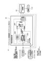
次に、図3は、第2の実施形態を示している。第2の実施形態の特徴は、減衰力可変型緩衝器以外の車載装置として車両に持ち込まれるモバイル機器を用いる構成としたことにある。なお、第2の実施形態では、上述した第1の実施形態と同一の構成要素に同一の符号を付し、その説明を省略するものとする。
Next, FIG. 3 shows a second embodiment. The feature of the second embodiment is that a mobile device brought into the vehicle is used as an in-vehicle device other than the variable damping force type shock absorber. In the second embodiment, the same components as those in the first embodiment described above are designated by the same reference numerals, and the description thereof will be omitted.
前述の第1の実施形態では、ナビゲーションシステム(ナビゲーション装置17)のセンサ情報を用いる構成としていた。これに対して、第2の実施形態では、ナビゲーションシステム(ナビゲーション装置17)に代えて、モバイル機器(モバイルシステム)のセンサ情報を用いる構成としている。即ち、第2の実施形態では、緩衝器7,10以外の車載装置は、車両に持ち込まれるモバイル機器となるスマートフォン31である。なお、第2の実施形態では、モバイル機器としてスマートフォン31を用いる場合を例に挙げて説明するが、例えば、携帯電話(フィーチャーフォン)、タブレット端末、タブレットPC等の各種の携帯情報端末、より具体的には、ジャイロセンサ等の状態検出センサが搭載された携帯情報端末を、モバイル機器として用いることができる。
In the above-mentioned first embodiment, the sensor information of the navigation system (navigation device 17) is used. On the other hand, in the second embodiment, the sensor information of the mobile device (mobile system) is used instead of the navigation system (navigation device 17). That is, in the second embodiment, the in-vehicle device other than the shock absorbers 7 and 10 is a smartphone 31 which is a mobile device brought into the vehicle. In the second embodiment, a case where a smartphone 31 is used as a mobile device will be described as an example, but for example, various mobile information terminals such as mobile phones (feature phones), tablet terminals, and tablet PCs, more specifically. Specifically, a mobile information terminal equipped with a state detection sensor such as a gyro sensor can be used as a mobile device.
第2の実施形態では、図1に仮想線(二点鎖線)で示すように、車両1にスマートフォン31が持ち込まれる。スマートフォン31は、ジャイロセンサ31Aおよび加速度センサ31Bが搭載されている。即ち、第2の実施形態では、サスペンションシステムは、車両1を制御するためのシステム以外の車載システムとなるモバイルシステム(スマートフォン31)のセンサ情報を、緩衝器7,10の制御に用いる。より具体的には、サスペンションシステムは、モバイルシステム(スマートフォン31)に搭載されたジャイロセンサ17Aおよび加速度センサ31Bの情報を、車両1の状態推定の観測値として用いる。
In the second embodiment, the smartphone 31 is brought into the vehicle 1 as shown by a virtual line (dashed-dotted line) in FIG. The smartphone 31 is equipped with a gyro sensor 31A and an acceleration sensor 31B. That is, in the second embodiment, the suspension system uses the sensor information of the mobile system (smartphone 31), which is an in-vehicle system other than the system for controlling the vehicle 1, to control the shock absorbers 7 and 10. More specifically, the suspension system uses the information of the gyro sensor 17A and the acceleration sensor 31B mounted on the mobile system (smartphone 31) as observation values for estimating the state of the vehicle 1.
図2に示すように、スマートフォン31は、車内LANとなるCAN16に接続されている。ジャイロセンサ31Aのセンサ情報となるジャイロ情報、および、加速度センサ31Bのセンサ情報となる加速度情報は、CAN16を介してコントローラ21に出力される。コントローラ21は、スマートフォン31のジャイロセンサ31Aの情報から車両1のロール方向の回転角速度とピッチ方向の回転角速度とを車両の回転運動として求める。即ち、コントローラ21の車体状態推定部22は、スマートフォン31のジャイロセンサ31Aで検出されたジャイロ情報であるピッチレイトおよびロールレイト(検出ピッチレイトおよび検出ロールレイト)を、車両1(車体2)の回転運動となるピッチレイトおよびロールレイト(車体ピッチレイトおよび車体ロールレイト)に変換する。
As shown in FIG. 2, the smartphone 31 is connected to the CAN 16 which is the in-vehicle LAN. The gyro information, which is the sensor information of the gyro sensor 31A, and the acceleration information, which is the sensor information of the acceleration sensor 31B, are output to the controller 21 via the CAN 16. The controller 21 obtains the rotational angular velocity in the roll direction and the rotational angular velocity in the pitch direction of the vehicle 1 as the rotational motion of the vehicle from the information of the gyro sensor 31A of the smartphone 31. That is, the vehicle body state estimation unit 22 of the controller 21 rotates the vehicle 1 (vehicle body 2) by rotating the pitch rate and roll rate (detection pitch rate and detection roll rate), which are gyro information detected by the gyro sensor 31A of the smartphone 31. It is converted into exercise pitch rate and roll rate (body pitch rate and body roll rate).
また、コントローラ21は、スマートフォン31に搭載された加速度センサ31Bから車両1のばね上上下加速度(車体2の上下方向の加速度)を求める。即ち、コントローラ21の車体状態推定部22は、スマートフォン31の加速度センサ31Bで検出された加速度情報である上下加速度(検出上下加速度)を、車体2の上下方向の加速度となるばね上上下加速度(車体上下加速度および車体上下加速度)に変換する。コントローラ21の車体状態推定部22は、車両1の回転運動(ピッチレイト、ロールレイト)とばね上上下加速度と車両1の走行状態情報(車体速度、車輪速度、前後加速度、横加速度、操舵角)とを基に、車両1の状態(ばね上速度、ピストン速度、ピストン変位、ロールレイト、ピッチレイト)を推定する。
Further, the controller 21 obtains the spring vertical acceleration of the vehicle 1 (the vertical acceleration of the vehicle body 2) from the acceleration sensor 31B mounted on the smartphone 31. That is, the vehicle body state estimation unit 22 of the controller 21 uses the vertical acceleration (detected vertical acceleration), which is the acceleration information detected by the acceleration sensor 31B of the smartphone 31, as the vertical acceleration of the vehicle body 2 (vehicle body). Convert to vertical acceleration and vertical acceleration of the vehicle body). The vehicle body state estimation unit 22 of the controller 21 includes the rotational motion (pitch rate, roll rate) of the vehicle 1, the vertical acceleration on the spring, and the running state information of the vehicle 1 (vehicle body speed, wheel speed, front-rear acceleration, lateral acceleration, steering angle). Based on the above, the state of the vehicle 1 (spring speed, piston speed, piston displacement, roll rate, pitch rate) is estimated.
このように、第2の実施形態では、サスペンションシステム以外の車載システムであるモバイルシステム(スマートフォン31)を備えている。そして、モバイルシステム(スマートフォン31)でセンシングされたピッチ方向およびロール方向のジャイロセンサの角速度情報(ピッチレイトおよびロールレイト)と、車体2(ばね上)の垂直方向の加速度情報(ばね上上下加速度)とが、追加のセンシング情報としてCAN16等の車内LAN通信を介してコントローラ21に入力される。即ち、第1の実施形態と比較すると、車体2(ばね上)の垂直方向の加速度情報(ばね上上下加速度)が、さらなる追加のセンシング情報としてコントローラ21に入力される。
As described above, in the second embodiment, the mobile system (smartphone 31), which is an in-vehicle system other than the suspension system, is provided. Then, the angular velocity information (pitch rate and roll rate) of the gyro sensor in the pitch direction and the roll direction sensed by the mobile system (smartphone 31) and the vertical acceleration information (on the spring) of the vehicle body 2 (on the spring). Is input to the controller 21 as additional sensing information via in-vehicle LAN communication such as CAN16. That is, as compared with the first embodiment, the vertical acceleration information (spring vertical acceleration) of the vehicle body 2 (on the spring) is input to the controller 21 as further additional sensing information.
ばね上上下加速度は、加速度センサの傾きにより、重力加速度の成分が重畳されるため、ジャイロ信号等からロール方向、ピッチ方向の傾き角度を算出し、または、加速度センサのDC成分から角度を算出し、その傾き分の重力成分を取り除くことで、正確なばね上加速度を算出することができる。そして、この正確なばね上上下加速度を、車体2の状態推定の観測値として使用することで、車両1(車体2)の状態推定精度を向上できる。
Since the component of gravity acceleration is superimposed on the vertical acceleration on the spring due to the tilt of the acceleration sensor, the tilt angle in the roll direction and pitch direction is calculated from the gyro signal, etc., or the angle is calculated from the DC component of the acceleration sensor. By removing the gravity component of the inclination, accurate spring acceleration can be calculated. Then, by using this accurate on-spring vertical acceleration as an observed value for estimating the state of the vehicle body 2, the accuracy of state estimation of the vehicle 1 (vehicle body 2) can be improved.
また、例えば、推定したばね上上下加速度またはばね上上下速度は、ノイズが取れるという利点があり、直接センシングしたばね上上下加速度またはこのばね上上下加速度から算出したばね上上下速度は、精度が良いという利点がある。このため、これらを用途に応じて用いることにより、サスペンションシステムの制御性能も向上できる。
Further, for example, the estimated spring vertical acceleration or spring vertical velocity has an advantage that noise can be removed, and the directly sensed spring vertical acceleration or the spring vertical velocity calculated from this spring vertical acceleration has good accuracy. There is an advantage. Therefore, the control performance of the suspension system can be improved by using these according to the application.
なお、第2の実施形態では、スマートフォン31によるピッチレイトとロールレイトとばね上加速度とを観測値として用いる構成とした場合を例に挙げて説明したが、例えば、スマートフォン31のばね上加速度のみを観測値として用いる構成としてもよい。また、例えば、第1の実施形態のナビゲーション装置17と第2の実施形態のスマートフォン31との両方を備える構成としてもよい。この場合には、例えば、ナビゲーション装置17によるピッチレイトとロールレイトとスマートフォン31によるばね上加速度を観測値として用いる構成としてもよい。
In the second embodiment, the case where the pitch rate, the roll rate, and the spring acceleration by the smartphone 31 are used as observation values has been described as an example. However, for example, only the spring acceleration of the smartphone 31 is used. It may be configured to be used as an observed value. Further, for example, the configuration may include both the navigation device 17 of the first embodiment and the smartphone 31 of the second embodiment. In this case, for example, the pitch rate and roll rate by the navigation device 17 and the spring acceleration by the smartphone 31 may be used as the observed values.
第2の実施形態は、上述の如きスマートフォン31によるセンサ情報を用いて車両1の状態を推定するもので、その基本的作用については、上述した第1の実施形態によるものと格別差異はない。特に、第2の実施形態では、緩衝器7,10以外の車載装置としてスマートフォン31を用いており、スマートフォン31は、ジャイロセンサ31Aと加速度センサ31Bとを有している。このため、これらのセンサ情報を用いることで、車両の状態推定の精度を向上できる。換言すれば、第2の実施形態では、スマートフォン31に搭載された加速度センサ31Bも用いて車両1の状態を推定することができる。このため、ジャイロセンサ31Aの情報に加えて、加速度センサ31Bのセンサ値(ばね上加速度)を観測値として使用することができる。これにより、ピストン速度の推定精度を向上させ、さらに正確なロールレイト、ピッチレイト、ばね上加速度(および/またはばね上速度)を制御に用いることができる。この結果、この面からも、制御性能を向上できる。
The second embodiment estimates the state of the vehicle 1 using the sensor information from the smartphone 31 as described above, and its basic operation is not particularly different from that according to the first embodiment described above. In particular, in the second embodiment, the smartphone 31 is used as an in-vehicle device other than the shock absorbers 7 and 10, and the smartphone 31 has a gyro sensor 31A and an acceleration sensor 31B. Therefore, by using these sensor information, the accuracy of vehicle state estimation can be improved. In other words, in the second embodiment, the state of the vehicle 1 can be estimated by using the acceleration sensor 31B mounted on the smartphone 31. Therefore, in addition to the information of the gyro sensor 31A, the sensor value (spring acceleration) of the acceleration sensor 31B can be used as the observed value. As a result, the estimation accuracy of the piston speed can be improved, and more accurate roll rate, pitch rate, and sprung acceleration (and / or sprung speed) can be used for control. As a result, the control performance can be improved from this aspect as well.
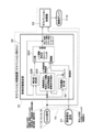
次に、図4は、第3の実施形態を示している。第3の実施形態の特徴は、減衰力可変型緩衝器以外の車載装置として外界認識システムを用いる構成としたことにある。なお、第3の実施形態では、上述した第1の実施形態と同一の構成要素に同一の符号を付し、その説明を省略するものとする。
Next, FIG. 4 shows a third embodiment. The feature of the third embodiment is that the external world recognition system is used as an in-vehicle device other than the variable damping force type shock absorber. In the third embodiment, the same components as those in the first embodiment described above are designated by the same reference numerals, and the description thereof will be omitted.
第3の実施形態では、外界認識システム(外界認識装置41)のセンサ情報を用いる。即ち、第3の実施形態では、緩衝器7,10以外の車載装置は、車両1の外界情報を認識可能な外界認識システム(外界認識装置41)である。外界認識システムを構成する外界認識装置41は、外界認識センサを有している。外界認識センサは、車両1の周囲の状態を認識する外界認識装置41のセンサである。換言すれば、外界認識センサは、車両1の周囲の物体の位置を計測するセンサである。外界認識センサは、例えば、ステレオカメラ、シングルカメラ等のカメラ(例えば、デジタルカメラ)、および/または、レーザレーダ、赤外線レーダ、ミリ波レーダ等のレーダ(例えば、半導体レーザ等の発光素子およびそれを受光する受光素子)を用いることができる。なお、外界認識センサは、カメラ、レーダに限らず、車両1の周囲となる外界の状態を認識(検出)できる各種のセンサ(検出装置、計測装置、電波探知機)を用いることができる。
In the third embodiment, the sensor information of the outside world recognition system (outside world recognition device 41) is used. That is, in the third embodiment, the in-vehicle device other than the shock absorbers 7 and 10 is an outside world recognition system (outside world recognition device 41) capable of recognizing the outside world information of the vehicle 1. The outside world recognition device 41 constituting the outside world recognition system has an outside world recognition sensor. The outside world recognition sensor is a sensor of the outside world recognition device 41 that recognizes the surrounding state of the vehicle 1. In other words, the outside world recognition sensor is a sensor that measures the position of an object around the vehicle 1. The external recognition sensor is, for example, a camera such as a stereo camera or a single camera (for example, a digital camera), and / or a radar such as a laser radar, an infrared radar, or a millimeter wave radar (for example, a light emitting element such as a semiconductor laser and a light emitting element thereof). A light receiving element) that receives light can be used. The outside world recognition sensor is not limited to the camera and radar, and various sensors (detection device, measurement device, radio wave detector) capable of recognizing (detecting) the state of the outside world around the vehicle 1 can be used.
第3の実施形態では、外界認識システム(外界認識装置41)は、車両1の外界情報として路面変位情報を取得する。即ち、第3の実施形態では、サスペンションシステムは、車両1を制御するためのシステム以外の車載システムとなる外界認識システム(外界認識装置41)のセンサ情報、即ち、カメラ、レーダ、ライダー等の外界認識センサのセンサ情報を、緩衝器7,10の制御に用いる。この場合、外界認識センサの外界情報となる路面変位情報を、車両1の状態推定の観測値として用いる。
In the third embodiment, the outside world recognition system (outside world recognition device 41) acquires road surface displacement information as the outside world information of the vehicle 1. That is, in the third embodiment, the suspension system is the sensor information of the outside world recognition system (outside world recognition device 41), which is an in-vehicle system other than the system for controlling the vehicle 1, that is, the outside world such as a camera, a radar, and a rider. The sensor information of the recognition sensor is used to control the shock absorbers 7 and 10. In this case, the road surface displacement information, which is the outside world information of the outside world recognition sensor, is used as the observed value for estimating the state of the vehicle 1.
図4に示すように、外界認識装置41は、車内LANとなるCAN16に接続されている。外界認識装置41のセンサ情報となる外界情報(路面変位情報)は、CAN16を介してコントローラ21に出力される。この場合、外界情報(路面変位情報)は、コントローラ21の車体状態推定部22(より具体的には、上下運動推定部22C)に入力される。コントローラ21の車体状態推定部22は、上下変動起因車輪速抽出部22Aと、補正値推定部22Bと、上下運動推定部22Cとに加えて、回転運動算出部42を備えている。
As shown in FIG. 4, the outside world recognition device 41 is connected to the CAN 16 which is an in-vehicle LAN. The outside world information (road surface displacement information), which is the sensor information of the outside world recognition device 41, is output to the controller 21 via the CAN 16. In this case, the external world information (road surface displacement information) is input to the vehicle body state estimation unit 22 (more specifically, the vertical motion estimation unit 22C) of the controller 21. The vehicle body state estimation unit 22 of the controller 21 includes a wheel speed extraction unit 22A due to vertical fluctuation, a correction value estimation unit 22B, a vertical motion estimation unit 22C, and a rotational motion calculation unit 42.
回転運動算出部42には、CAN16を介して車体速度、車輪速度、前後加速度、横加速度、操舵角が入力される。回転運動算出部42は、特許文献1に記載された「回転運動推定部51」と同様に、回転運動状態量を推定する。即ち、回転運動算出部42は、車体速度、車輪速度、前後加速度、横加速度、操舵角を入力として、運動方程式やフィルタ、ゲインに基づいて、車両1のピッチ方向の回転角速度となるピッチレイトを算出し、算出されたピッチレイトを上下運動推定部22Cに出力する。ピッチレイトの算出の処理については、特許文献1等の公開公報を含む各種の文献(車両状態の推定に関する文献)に記載されているため、これ以上の説明は省略する。
The vehicle body speed, wheel speed, front-rear acceleration, lateral acceleration, and steering angle are input to the rotational motion calculation unit 42 via the CAN 16. The rotational motion calculation unit 42 estimates the rotational motion state quantity in the same manner as the “rotational motion estimation unit 51” described in Patent Document 1. That is, the rotational motion calculation unit 42 inputs the vehicle body speed, wheel speed, front-rear acceleration, lateral acceleration, and steering angle, and based on the motion equation, the filter, and the gain, obtains a pitch rate that is the rotational angular velocity of the vehicle 1 in the pitch direction. It is calculated, and the calculated pitch rate is output to the vertical motion estimation unit 22C. Since the process of calculating the pitch rate is described in various documents (literatures relating to estimation of vehicle state) including publications such as Patent Document 1, further description thereof will be omitted.
上下運動推定部22Cには、補正値推定部22Bからの補正値と、上下変動起因車輪速抽出部22Aからの上下変動起因車輪速度とが入力されることに加えて、回転運動算出部42からのピッチレイトと、外界認識装置41の外界認識センサからの路面変位が入力される。上下運動推定部22Cは、入力値となる補正値と、観測値となる上下変動起因車輪速度、ピッチレイトおよび路面変位とに基づいて車両1の状態値となるばね上速度、ピストン速度、ピストン変位、ロールレイト、ピッチレイトを推定する。
In addition to inputting the correction value from the correction value estimation unit 22B and the wheel speed caused by the vertical movement from the wheel speed extraction unit 22A caused by the vertical movement, the vertical movement estimation unit 22C is input from the rotational movement calculation unit 42. And the road surface displacement from the outside world recognition sensor of the outside world recognition device 41 are input. The vertical motion estimation unit 22C has a spring speed, a piston speed, and a piston displacement that are state values of the vehicle 1 based on a correction value that is an input value and a wheel speed, a pitch rate, and a road surface displacement that are caused by vertical fluctuations that are observed values. , Roll rate, pitch rate is estimated.
このように、第3の実施形態では、サスペンションシステム以外の車載システムである外界認識システム(外界認識装置41)を備えている。そして、外界認識システム(外界認識装置41)の外界認識センサ(例えば、カメラ、ライダー等)でセンシングした路面変位情報が、追加のセンシング情報としてCAN16等の車内LAN通信を介してコントローラ21に入力される。第3の実施形態では、正確な路面変位情報を観測値として入力することにより、車両1(車体2)の状態推定精度を向上できる。この結果、サスペンション制御への入力信号の精度が向上するため、サスペンションシステムの性能も向上できる。なお、第3の実施形態では、路面変位情報を観測値として追加しているが、例えば、第1の実施形態または第2の実施形態で、観測値として路面変位情報を追加してもよい。
As described above, in the third embodiment, the outside world recognition system (outside world recognition device 41), which is an in-vehicle system other than the suspension system, is provided. Then, the road surface displacement information sensed by the outside world recognition sensor (for example, camera, rider, etc.) of the outside world recognition system (outside world recognition device 41) is input to the controller 21 as additional sensing information via in-vehicle LAN communication such as CAN16. To. In the third embodiment, the state estimation accuracy of the vehicle 1 (vehicle body 2) can be improved by inputting accurate road surface displacement information as an observed value. As a result, the accuracy of the input signal to the suspension control is improved, so that the performance of the suspension system can also be improved. In the third embodiment, the road surface displacement information is added as an observed value, but for example, in the first embodiment or the second embodiment, the road surface displacement information may be added as an observed value.
第3の実施形態は、上述の如き外界認識装置41によるセンサ情報(路面変位)を用いて車両1の状態を推定するもので、その基本的作用については、上述した第1の実施形態によるものと格別差異はない。特に、第3の実施形態では、緩衝器7,10以外の車載装置として外界認識システム(外界認識装置41)を用いている。このため、外界認識システム(外界認識装置41)の外界認識センサの情報(路面変位情報)を観測値として車両1の状態推定に用いることができる。この場合、カメラ、レーダ、ライダー等の外界認識センサから得られる外界情報を用いることで、車両1の状態推定の精度を向上できる。
The third embodiment estimates the state of the vehicle 1 by using the sensor information (road surface displacement) by the external world recognition device 41 as described above, and the basic operation thereof is based on the first embodiment described above. There is no particular difference. In particular, in the third embodiment, the outside world recognition system (outside world recognition device 41) is used as an in-vehicle device other than the shock absorbers 7 and 10. Therefore, the information (road surface displacement information) of the outside world recognition sensor of the outside world recognition system (outside world recognition device 41) can be used as an observed value for estimating the state of the vehicle 1. In this case, the accuracy of state estimation of the vehicle 1 can be improved by using the outside world information obtained from the outside world recognition sensors such as a camera, radar, and rider.
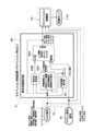
次に、図5は、第4の実施形態を示している。第4の実施形態の特徴は、減衰力可変型緩衝器以外の車載装置としてヘッドライトシステムを用いる構成としたことにある。なお、第4の実施形態では、上述した第1の実施形態および第3の実施形態と同一の構成要素に同一の符号を付し、その説明を省略するものとする。
Next, FIG. 5 shows a fourth embodiment. The feature of the fourth embodiment is that the headlight system is used as an in-vehicle device other than the variable damping force type shock absorber. In the fourth embodiment, the same components as those in the first embodiment and the third embodiment described above are designated by the same reference numerals, and the description thereof will be omitted.
第4の実施形態では、車両1に搭載されたヘッドライトシステム(ヘッドライト装置)の車高センサ51の情報を用いる。即ち、第4の実施形態では、緩衝器7,10専用以外の車載装置のセンサは、車体2の車高を検知可能な車高センサ51である。この場合、車高センサ51は、緩衝器7,10専用以外の車載装置である車両1のヘッドライトシステムの車高センサである。ヘッドライトオートレベリングシステムとも呼ばれるヘッドライトシステムは、車両1の車高に応じてヘッドライトの角度を自動で変更することにより、車高の変化に拘わらずヘッドライトの光軸を適正に維持する。第4の実施形態では、サスペンションシステムは、車両1を制御するためのシステム以外の車載システムとなるヘッドライトシステムのセンサ情報、即ち、ヘッドライトシステムの車高センサ51の情報を、緩衝器7,10の制御に用いる。
In the fourth embodiment, the information of the vehicle height sensor 51 of the headlight system (headlight device) mounted on the vehicle 1 is used. That is, in the fourth embodiment, the sensor of the vehicle-mounted device other than the shock absorbers 7 and 10 is the vehicle height sensor 51 that can detect the vehicle height of the vehicle body 2. In this case, the vehicle height sensor 51 is a vehicle height sensor of the headlight system of the vehicle 1, which is an in-vehicle device other than the shock absorbers 7 and 10. The headlight system, which is also called a headlight auto-leveling system, automatically maintains the optical axis of the headlights regardless of changes in the vehicle height by automatically changing the angle of the headlights according to the vehicle height of the vehicle 1. In the fourth embodiment, the suspension system uses the sensor information of the headlight system, which is an in-vehicle system other than the system for controlling the vehicle 1, that is, the information of the vehicle height sensor 51 of the headlight system, as a shock absorber 7. Used for control of 10.
ヘッドライトシステムの車高センサ51の情報は、例えば、緩衝器7,10の変位(ピストン変位)としてコントローラ21に入力される。即ち、第4の実施形態では、車高センサ51によるピストン変位を車両1の状態推定の観測値として用いる。図5に示すように、車高センサ51は、車内LANとなるCAN16に接続されている。車高センサ51によるピストン変位は、CAN16を介してコントローラ21に出力される。この場合、車高センサ51によるピストン変位は、コントローラ21の車体状態推定部22(より具体的には、上下運動推定部22C)、および、コントローラ21のサスペンション制御部23に入力される。
The information of the vehicle height sensor 51 of the headlight system is input to the controller 21 as, for example, the displacement (piston displacement) of the shock absorbers 7 and 10. That is, in the fourth embodiment, the piston displacement by the vehicle height sensor 51 is used as the observed value for estimating the state of the vehicle 1. As shown in FIG. 5, the vehicle height sensor 51 is connected to CAN 16 which is an in-vehicle LAN. The piston displacement by the vehicle height sensor 51 is output to the controller 21 via the CAN 16. In this case, the piston displacement by the vehicle height sensor 51 is input to the vehicle body state estimation unit 22 (more specifically, the vertical motion estimation unit 22C) of the controller 21 and the suspension control unit 23 of the controller 21.
このように、第4の実施形態では、サスペンションシステム以外の車載システムであるヘッドライトシステム(車高センサ51)を備えている。そして、ヘッドライトシステム(車高センサ51)でセンシングされたピストン変位情報が、追加のセンシング情報としてCAN16等の車内LAN通信を介してコントローラ21に入力される。第4の実施形態では、精度の良いピストン変位を観測値として入力することにより、車両1(車体2)の状態推定精度を向上できる。また、推定したピストン変位はノイズが取れるという利点があり、直接センシングしたピストン変位は精度が良いという利点がある。これらを用途に応じて用いることにより、サスペンションシステムの性能を向上することができる。なお、第4の実施形態では、ピストン変位情報を観測値として追加しているが、例えば、第1の実施形態ないし第3の実施形態で、観測値としてピストン変位情報を追加してもよい。
As described above, in the fourth embodiment, the headlight system (vehicle height sensor 51), which is an in-vehicle system other than the suspension system, is provided. Then, the piston displacement information sensed by the headlight system (vehicle height sensor 51) is input to the controller 21 as additional sensing information via in-vehicle LAN communication such as CAN 16. In the fourth embodiment, the state estimation accuracy of the vehicle 1 (vehicle body 2) can be improved by inputting an accurate piston displacement as an observed value. Further, the estimated piston displacement has an advantage that noise can be removed, and the directly sensed piston displacement has an advantage that the accuracy is good. By using these according to the application, the performance of the suspension system can be improved. In the fourth embodiment, the piston displacement information is added as an observed value, but for example, in the first embodiment to the third embodiment, the piston displacement information may be added as an observed value.
第4の実施形態は、上述の如きヘッドライトシステムの車高センサ51の情報(ピストン変位)を用いて車両1の状態を推定するもので、その基本的作用については、上述した第1の実施形態ないし第3の実施形態によるものと格別差異はない。特に、第4の実施形態では、緩衝器7,10以外の車載装置のセンサとして、ヘッドライトシステムの車高センサ51を用いている。このため、緩衝器7,10以外の他のシステム(ヘッドライトシステム)の車高センサ51の情報(ピストン変位情報)を観測値として車両1の状態推定に用いることができ、車両1の状態推定の精度を向上できる。
The fourth embodiment estimates the state of the vehicle 1 using the information (piston displacement) of the vehicle height sensor 51 of the headlight system as described above, and the basic operation thereof is the first embodiment described above. There is no particular difference from the one according to the embodiment or the third embodiment. In particular, in the fourth embodiment, the vehicle height sensor 51 of the headlight system is used as the sensor of the vehicle-mounted device other than the shock absorbers 7 and 10. Therefore, the information (piston displacement information) of the vehicle height sensor 51 of the system (headlight system) other than the shock absorbers 7 and 10 can be used for the state estimation of the vehicle 1 as the observed value, and the state estimation of the vehicle 1 can be used. The accuracy of the can be improved.
次に、図6は、第5の実施形態を示している。第5の実施形態の特徴は、モバイル機器のセンサ情報を減衰力可変型緩衝器の制御に用いる構成としたことにある。なお、第5の実施形態では、上述した第1の実施形態ないし第4の実施形態と同一の構成要素に同一の符号を付し、その説明を省略するものとする。
Next, FIG. 6 shows a fifth embodiment. A feature of the fifth embodiment is that the sensor information of the mobile device is used for controlling the variable damping force shock absorber. In the fifth embodiment, the same components as those in the first to fourth embodiments described above are designated by the same reference numerals, and the description thereof will be omitted.
第5の実施形態は、車両を制御するためのシステム以外の車載システムであるモバイルシステム(スマートフォン31)のセンサ情報を、緩衝器7,10の制御に用いる。この場合、コントローラ21は、車両に持ち込まれるモバイル機器であるスマートフォン31を検出するモバイル機器検出部61を有している。モバイル機器検出部61は、3つの入力端子61A,61B,61Cと1つの出力端子61Dとを有するスイッチとして構成されている。モバイル機器検出部61の第1入力端子61Aおよび第2入力端子61Bは、スマートフォン31の出力側と接続される。
In the fifth embodiment, the sensor information of the mobile system (smartphone 31), which is an in-vehicle system other than the system for controlling the vehicle, is used for controlling the shock absorbers 7 and 10. In this case, the controller 21 has a mobile device detection unit 61 that detects the smartphone 31, which is a mobile device brought into the vehicle. The mobile device detection unit 61 is configured as a switch having three input terminals 61A, 61B, 61C and one output terminal 61D. The first input terminal 61A and the second input terminal 61B of the mobile device detection unit 61 are connected to the output side of the smartphone 31.
第1入力端子61Aは、スマートフォン31のセンサ情報、即ち、スマートフォン31で検出されたばね上加速度、ロールレイト、ピッチレイトを用いて緩衝器7,10の制御を行うときに出力端子61Dと接続される。第2入力端子61Bは、スマートフォン31の信号の有無を検出するときに切換えられる。第3入力端子61Cは、車体状態推定部22(上下運動推定部22C)の出力側と接続されている。第3入力端子61Cは、スマートフォン31のセンサ情報を用いることができないとき、換言すれば、車体状態推定部22で推定されたばね上速度、ロールレイト、ピッチレイトを用いて緩衝器7,10の制御を行うときに出力端子61Dと接続される。
The first input terminal 61A is connected to the output terminal 61D when the shock absorbers 7 and 10 are controlled using the sensor information of the smartphone 31, that is, the spring acceleration, the roll rate, and the pitch rate detected by the smartphone 31. .. The second input terminal 61B is switched when detecting the presence / absence of a signal of the smartphone 31. The third input terminal 61C is connected to the output side of the vehicle body state estimation unit 22 (vertical motion estimation unit 22C). When the sensor information of the smartphone 31 cannot be used, the third input terminal 61C controls the shock absorbers 7 and 10 by using the sprung velocity, the roll rate, and the pitch rate estimated by the vehicle body state estimation unit 22. Is connected to the output terminal 61D.
なお、第5の実施形態では、上下運動推定部22Cの出力側は、モバイル機器検出部61とサスペンション制御部23とに接続されている。上下運動推定部22Cで推定されたばね上速度、ロールレイト、ピッチレイトは、モバイル機器検出部61に入力される。上下運動推定部22Cで推定されたピストン速度およびピストン変位は、モバイル機器検出部61を介することなくサスペンション制御部23に入力される。
In the fifth embodiment, the output side of the vertical motion estimation unit 22C is connected to the mobile device detection unit 61 and the suspension control unit 23. The sprung velocity, roll rate, and pitch rate estimated by the vertical motion estimation unit 22C are input to the mobile device detection unit 61. The piston speed and piston displacement estimated by the vertical motion estimation unit 22C are input to the suspension control unit 23 without going through the mobile device detection unit 61.
モバイル機器検出部61は、車両1内に持ち込まれたスマートフォン31のセンサ情報を使用することができるか否かの検出を行い、この検出結果に応じて切換えられる。スマートフォン31が検出されたときは、モバイル機器検出部61は、第1入力端子61Aと出力端子61Dとを接続する。スマートフォン31が検出されないときは、モバイル機器検出部61は、第3入力端子61Cと出力端子61Dとを接続する。
The mobile device detection unit 61 detects whether or not the sensor information of the smartphone 31 brought into the vehicle 1 can be used, and is switched according to the detection result. When the smartphone 31 is detected, the mobile device detection unit 61 connects the first input terminal 61A and the output terminal 61D. When the smartphone 31 is not detected, the mobile device detection unit 61 connects the third input terminal 61C and the output terminal 61D.
このように、モバイル機器検出部61は、スマートフォン31の検出の有無に応じて切換えられる。これにより、コントローラ21は、モバイル機器検出部61によりスマートフォン31が検出された場合は、スマートフォン31のジャイロセンサ31Aの情報から車両1のロール方向の回転角速度とピッチ方向の回転角速度とを車両1の回転運動(ロールレイト、ピッチレイト)として求め、推定された車両の状態(ピストン速度、ピストン変位)と車両の回転運動(ロールレイト、ピッチレイト)と加速度センサ31Bのばね上加速度とに応じて、緩衝器7,10に制御信号を出力する。これに対して、モバイル機器検出部61によりスマートフォン31が検出されない場合は、コントローラ21は、車体状態推定部22で推定された車両1の状態(ピストン速度、ピストン変位、ばね上速度、ロールレイト、ピッチレイト)に応じて緩衝器7,10に制御信号を出力する。
In this way, the mobile device detection unit 61 is switched according to the presence or absence of detection of the smartphone 31. As a result, when the smartphone 31 is detected by the mobile device detection unit 61, the controller 21 determines the rotation angular velocity of the vehicle 1 in the roll direction and the rotation angular velocity in the pitch direction from the information of the gyro sensor 31A of the smartphone 31. Obtained as rotational motion (roll rate, pitch rate), depending on the estimated vehicle state (piston velocity, piston displacement), vehicle rotational motion (roll rate, pitch rate), and spring acceleration of the acceleration sensor 31B. A control signal is output to the shock absorbers 7 and 10. On the other hand, when the smartphone 31 is not detected by the mobile device detection unit 61, the controller 21 determines the state of the vehicle 1 (piston speed, piston displacement, sprung speed, roll rate, etc.) estimated by the vehicle body state estimation unit 22. A control signal is output to the shock absorbers 7 and 10 according to the pitch rate).
このように、第5の実施形態では、スマートフォン31によるばね上の垂直方向の加速度情報、ロールレイト情報、ピッチレイト情報が、追加のセンシング情報となっている。前述の第2の実施形態では、スマートフォン31のセンシング情報を観測値として用いることにより、車両1(車体2)の状態推定精度を向上させている。これに対して、第5の実施形態では、車両1(車体2)の状態推定は、従来の状態推定の技術を利用する。即ち、車両1(車体2)の状態推定に、スマートフォン31によるセンシング情報は用いない。第5の実施形態では、スマートフォン31のセンシング情報(ばね上加速度、ロールレイト、ピッチレイト)が取得可能な場合は、このスマートフォン31のセンシング情報を用いる。一方、スマートフォン31が未接続や故障により、スマートフォン31のセンシング情報を取得できない場合は、推定値を用いる。また、ピストン速度とピストン変位については、推定値を用いており、ばね上速度、ロールレイト、ピッチレイトはセンシング値から算出または直接センシングした値を用いるため、サスペンションシステムの性能を向上できる。
As described above, in the fifth embodiment, the vertical acceleration information, the roll rate information, and the pitch rate information on the spring by the smartphone 31 are additional sensing information. In the second embodiment described above, the state estimation accuracy of the vehicle 1 (vehicle body 2) is improved by using the sensing information of the smartphone 31 as an observed value. On the other hand, in the fifth embodiment, the state estimation of the vehicle 1 (vehicle body 2) uses the conventional state estimation technique. That is, the sensing information by the smartphone 31 is not used for estimating the state of the vehicle 1 (vehicle body 2). In the fifth embodiment, when the sensing information (spring acceleration, roll rate, pitch rate) of the smartphone 31 can be acquired, the sensing information of the smartphone 31 is used. On the other hand, when the smartphone 31 cannot acquire the sensing information of the smartphone 31 due to non-connection or failure, the estimated value is used. Further, since the estimated values are used for the piston speed and the piston displacement, and the values calculated from the sensing values or directly sensed are used for the sprung speed, the roll rate, and the pitch rate, the performance of the suspension system can be improved.
第5の実施形態は、上述の如きモバイル機器検出部61によりスマートフォン31のセンサ情報を用いるか否かを選択する構成としたもので、その基本的作用については、上述した第1の実施形態ないし第4の実施形態によるものと格別差異はない。特に、第5の実施形態では、スマートフォン31のセンサ情報として、ばね上の垂直方向の加速度、ロールレイト、ピッチレイト情報を用いることができる。そして、スマートフォン31のセンシング情報(ばね上加速度、ロールレイト、ピッチレイト)が取得可能な場合は、スマートフォン31の情報を用いて制御を行うことができ、スマートフォン31が未接続または故障により入手不能の場合には、スマートフォン31の情報を用いずに制御を行うことができる。このため、スマートフォン31の情報の有無に応じて適切な制御を行うことができる。
The fifth embodiment is configured to select whether or not to use the sensor information of the smartphone 31 by the mobile device detection unit 61 as described above, and the basic operation thereof is the above-mentioned first embodiment or the above-mentioned first embodiment. There is no particular difference from that according to the fourth embodiment. In particular, in the fifth embodiment, vertical acceleration on the spring, roll rate, and pitch rate information can be used as the sensor information of the smartphone 31. If the sensing information (spring acceleration, roll rate, pitch rate) of the smartphone 31 can be acquired, control can be performed using the information of the smartphone 31, and the smartphone 31 cannot be obtained due to unconnected or malfunction. In this case, control can be performed without using the information of the smartphone 31. Therefore, appropriate control can be performed depending on the presence or absence of information on the smartphone 31.
なお、第5の実施形態および前述の第2の実施形態では、モバイル機器としてスマートフォン31を例に挙げて説明した。しかし、これに限らず、モバイル機器は、携帯電話(フィーチャーフォン)、タブレット端末、タブレットPC等、各種の携帯情報端末を用いることができる。また、モバイル機器のセンサとして、ジャイロセンサ31Aと加速度センサ31Bを例に挙げて説明した。しかし、これに限らず、例えば、地磁気センサ等、モバイル装置に搭載された加速度センサまたはジャイロセンサ以外の各種センサ(動きを検出する各種センサ)を用いてもよい。また、加速度センサとジャイロセンサとのうちの何れか一方のみを用いてもよい。
In the fifth embodiment and the second embodiment described above, the smartphone 31 has been described as an example as a mobile device. However, the mobile device is not limited to this, and various mobile information terminals such as mobile phones (feature phones), tablet terminals, and tablet PCs can be used. Further, as the sensors of the mobile device, the gyro sensor 31A and the acceleration sensor 31B have been described as examples. However, the present invention is not limited to this, and various sensors (various sensors for detecting motion) other than the acceleration sensor or the gyro sensor mounted on the mobile device, such as a geomagnetic sensor, may be used. Further, only one of the acceleration sensor and the gyro sensor may be used.
第1の実施形態および第2の実施形態では、ジャイロセンサ17A,31Aの情報としてロールレイトとピッチレイトを用いる構成とした場合を例に挙げて説明した。しかし、これに限らず、例えば、ロールレイトとピッチレイトとのうちの一方を用いる構成としてもよい。即ち、ジャイロ情報は、ロールレイトとピッチレイトとヨーレイトとのうちの少なくともいずれか、より好ましくは、ロールレイトとピッチレイトとの少なくとも一方を用いることができる。さらに、各実施形態は例示であり、異なる実施形態で示した構成の部分的な置換または組み合わせが可能であることは言うまでもない。
In the first embodiment and the second embodiment, the case where the roll rate and the pitch rate are used as the information of the gyro sensors 17A and 31A has been described as an example. However, the present invention is not limited to this, and for example, one of a roll rate and a pitch rate may be used. That is, as the gyro information, at least one of roll rate, pitch rate and yaw rate, more preferably at least one of roll rate and pitch rate can be used. Furthermore, it is needless to say that each embodiment is exemplary and the configurations shown in different embodiments can be partially replaced or combined.
以上説明した実施形態に基づく車両制御装置およびサスペンションシステムとして、例えば下記に述べる態様のものが考えられる。
As the vehicle control device and suspension system based on the embodiment described above, for example, the ones described below can be considered.
第1の態様としては、車両に設けられた車輪速センサから前記車両の状態を推定し、推定された前記車両の状態に応じて車輪と車体との間に設けられた減衰力可変型緩衝器に制御信号を出力する車両制御装置において、前記減衰力可変型緩衝器専用以外の車載装置のセンサの情報を観測値として前記車両の状態推定に用いる。
In the first aspect, the state of the vehicle is estimated from the wheel speed sensor provided in the vehicle, and the damping force variable shock absorber provided between the wheel and the vehicle body according to the estimated state of the vehicle. In the vehicle control device that outputs the control signal to the vehicle, the information of the sensor of the in-vehicle device other than the variable damping force type shock absorber is used as the observed value for estimating the state of the vehicle.
この第1の態様によれば、減衰力可変型緩衝器専用以外の車載装置のセンサの情報を観測値として車両の状態推定に用いるため、車両の状態推定精度を向上できる。即ち、減衰力可変型緩衝器専用のセンサを持たないセンサレスの構成でも、車載装置(例えば、ナビゲーションシステム、スマートフォン等)のセンサ(例えば、ジャイロセンサ、加速度センサ等)の情報を観測値として車両状態(例えば、車体上下運動、車速度、制駆動状態、車輪スリップ等)の推定に用いることができる。このため、車両状態の推定精度が良くなり、減衰力可変型緩衝器による制振性能を向上できる。換言すれば、車両状態の推定の観測値に推定値ではなくセンシングによる精度のよい値を用いることができ、推定精度を向上できる。
According to this first aspect, since the information of the sensor of the in-vehicle device other than the variable damping force type shock absorber is used as the observed value for the vehicle state estimation, the vehicle state estimation accuracy can be improved. That is, even in a sensorless configuration that does not have a sensor dedicated to the variable damping force shock absorber, the vehicle state is based on the information of the sensor (for example, gyro sensor, acceleration sensor, etc.) of the in-vehicle device (for example, navigation system, smartphone, etc.). It can be used for estimating (for example, vehicle body vertical movement, vehicle speed, controlled drive state, wheel slip, etc.). Therefore, the estimation accuracy of the vehicle state is improved, and the vibration damping performance by the variable damping force shock absorber can be improved. In other words, it is possible to use an accurate value by sensing instead of the estimated value as the observed value for estimating the vehicle state, and the estimation accuracy can be improved.
第2の態様としては、第1の態様において、前記車載装置のセンサの情報は、前記車載装置に搭載されたジャイロセンサのジャイロ情報である。この第2の態様によれば、車載装置のジャイロセンサのジャイロ情報を観測値として車両の状態推定に用いることができる。
As a second aspect, in the first aspect, the information of the sensor of the vehicle-mounted device is the gyro information of the gyro sensor mounted on the vehicle-mounted device. According to this second aspect, the gyro information of the gyro sensor of the in-vehicle device can be used as an observed value for estimating the state of the vehicle.
第3の態様としては、第2の態様において、前記車両制御装置は、前記ジャイロセンサの情報から前記車両のロール方向の回転角速度とピッチ方向の回転角速度との少なくとも一方を車両の回転運動として求め、求められた前記車両の回転運動と車両の走行状態情報とを基に前記車両の状態を推定する。この第3の態様によれば、ジャイロセンサの情報から求められる車両の回転運動(例えば、ロールレイト、ピッチレイト等)と車両の走行状態情報(例えば、車輪速センサから得られる車輪速度、車体速度等のCAN情報)を基に車両の状態を推定することができる。ジャイロセンサは、車載装置の設置角度の影響を受けずに、正確なロールレイト、ピッチレイトを測定することができる。このため、車載装置からの正確なロールレイトとピッチレイトの少なくとも一方を観測値として推定に用いることで、ばね上速度、ピストン速度等の推定精度を向上できる。
As a third aspect, in the second aspect, the vehicle control device obtains at least one of the rotation angular velocity in the roll direction and the rotation angular velocity in the pitch direction of the vehicle as the rotational motion of the vehicle from the information of the gyro sensor. , The state of the vehicle is estimated based on the obtained rotational motion of the vehicle and the traveling state information of the vehicle. According to this third aspect, the rotational motion of the vehicle (for example, roll rate, pitch rate, etc.) obtained from the information of the gyro sensor and the running state information of the vehicle (for example, the wheel speed and the vehicle body speed obtained from the wheel speed sensor). Can information such as) can be used to estimate the state of the vehicle. The gyro sensor can accurately measure the roll rate and pitch rate without being affected by the installation angle of the in-vehicle device. Therefore, by using at least one of the accurate roll rate and pitch rate from the in-vehicle device as the observed value for estimation, it is possible to improve the estimation accuracy of the sprung speed, the piston speed, and the like.
第4の態様としては、第3の態様において、前記車両制御装置は、推定された前記車両の状態と前記車両の回転運動とに応じて前記減衰力可変型緩衝器に制御信号を出力する。この第4の態様によれば、ジャイロセンサの情報から求められる車両の回転運動を車両の状態推定に用いることに加えて、制御信号の出力にも用いる。このため、正確なロールレイト、ピッチレイトを用いて制御信号を出力でき、制御性能を向上できる。
As a fourth aspect, in the third aspect, the vehicle control device outputs a control signal to the damping force variable shock absorber according to the estimated state of the vehicle and the rotational movement of the vehicle. According to this fourth aspect, in addition to using the rotational motion of the vehicle obtained from the information of the gyro sensor for estimating the state of the vehicle, it is also used for outputting a control signal. Therefore, the control signal can be output using the accurate roll rate and pitch rate, and the control performance can be improved.
第5の態様としては、第3の態様において、前記車両の走行状態情報は、少なくとも車輪速度情報を含み、前記車両制御装置は、前記車輪速度情報から前記車両の上下運動を求め、前記車両の上下運動と前記車両の回転運動とから前記車両の状態を推定する。この第5の態様によれば、ジャイロセンサの情報から求められる車両の回転運動(例えば、ロールレイト、ピッチレイト等)と車輪速度情報を含む車両の走行状態情報を基に車両の状態を推定することができる。
As a fifth aspect, in the third aspect, the traveling state information of the vehicle includes at least wheel speed information, and the vehicle control device obtains the vertical movement of the vehicle from the wheel speed information, and the vehicle's vertical motion is obtained. The state of the vehicle is estimated from the vertical movement and the rotational movement of the vehicle. According to this fifth aspect, the state of the vehicle is estimated based on the running state information of the vehicle including the rotational motion (for example, roll rate, pitch rate, etc.) of the vehicle obtained from the information of the gyro sensor and the wheel speed information. be able to.
第6の態様としては、第5の態様において、前記車両制御装置は、前記車輪速度情報と前記車両の回転運動とから前記車両の上下運動を求め、前記車両の上下運動と前記車両の回転運動とから前記車両の状態を推定する。この第6の態様によれば、車両の上下運動と車両の回転運動とから車両の状態を推定することができる。
As a sixth aspect, in the fifth aspect, the vehicle control device obtains the vertical movement of the vehicle from the wheel speed information and the rotational movement of the vehicle, and the vertical movement of the vehicle and the rotational movement of the vehicle. The state of the vehicle is estimated from the above. According to this sixth aspect, the state of the vehicle can be estimated from the vertical movement of the vehicle and the rotational movement of the vehicle.
第7の態様としては、第2の態様において、前記車両制御装置は、前記ジャイロセンサの情報から前記車両のロール方向の回転角速度とピッチ方向の回転角速度との少なくとも一方を車両の回転運動として求め、さらに、前記減衰力可変型緩衝器専用以外の車載装置に搭載された加速度センサから前記車両のばね上上下加速度を求め、前記車両の回転運動と前記ばね上上下加速度と前記車両の走行状態情報とを基に前記車両の状態を推定する。
As a seventh aspect, in the second aspect, the vehicle control device obtains at least one of the rotation angular velocity in the roll direction and the rotation angular velocity in the pitch direction of the vehicle as the rotational motion of the vehicle from the information of the gyro sensor. Further, the vertical acceleration on the spring of the vehicle is obtained from an acceleration sensor mounted on an in-vehicle device other than the variable damping force shock absorber, and the rotational motion of the vehicle, the vertical acceleration on the spring, and the running state information of the vehicle are obtained. The state of the vehicle is estimated based on the above.
この第7の態様によれば、車載装置に搭載された加速度センサも用いて車両の状態を推定することができる。即ち、ジャイロセンサの情報に加えて、加速度センサのセンサ値(ばね上加速度)を観測値として使用することができる。これにより、状態推定の推定精度を向上させ、さらに正確なロールレイト、ピッチレイト、ばね上加速度(および/またはばね上速度)を制御に用いることができる。このため、この面からも、制御性能を向上できる。また、ジャイロセンサの情報から求められる車両の回転運動(例えば、ロールレイト、ピッチレイト等)から加速度センサのセンサ値から求められる重力成分を除くことでも状態推定の推定精度の向上が図れる。
According to this seventh aspect, the state of the vehicle can be estimated by using the acceleration sensor mounted on the in-vehicle device. That is, in addition to the information of the gyro sensor, the sensor value (spring acceleration) of the acceleration sensor can be used as the observed value. This makes it possible to improve the estimation accuracy of the state estimation and use more accurate roll rate, pitch rate, and sprung acceleration (and / or sprung velocity) for control. Therefore, the control performance can be improved from this aspect as well. Further, the estimation accuracy of the state estimation can be improved by removing the gravity component obtained from the sensor value of the acceleration sensor from the rotational motion of the vehicle (for example, roll rate, pitch rate, etc.) obtained from the information of the gyro sensor.
第8の態様としては、第1の態様において、前記減衰力可変型緩衝器専用以外の車載装置は、ナビゲーションシステムである。この第8の態様によれば、ナビゲーションシステムのセンサの情報を観測値として車両の状態推定に用いることができる。この場合、ナビゲーションシステムは、ジャイロセンサを有しており、かつ、車両の搭載位置も固定されているため、車両の状態推定の精度を向上できる。
As an eighth aspect, in the first aspect, the in-vehicle device other than the dedicated damping force variable shock absorber is a navigation system. According to this eighth aspect, the information of the sensor of the navigation system can be used as the observed value for estimating the state of the vehicle. In this case, since the navigation system has a gyro sensor and the mounting position of the vehicle is fixed, the accuracy of vehicle state estimation can be improved.
第9の態様としては、第1の態様において、前記減衰力可変型緩衝器専用以外の車載装置は、車両に持ち込まれるモバイル機器である。この第9の態様によれば、スマートフォン、タブレット等のモバイル機器のセンサの情報を観測値として車両の状態推定に用いることができる。この場合、モバイル機器は、ジャイロセンサ、加速度センサを有しており、これらのセンサ情報を用いることで、車両の状態推定の精度を向上できる。
As a ninth aspect, in the first aspect, the in-vehicle device other than the variable damping force type shock absorber is a mobile device brought into the vehicle. According to this ninth aspect, the information of the sensor of the mobile device such as a smartphone or a tablet can be used as an observation value for estimating the state of the vehicle. In this case, the mobile device has a gyro sensor and an acceleration sensor, and by using these sensor information, the accuracy of vehicle state estimation can be improved.
第10の態様としては、第1の態様において、前記減衰力可変型緩衝器専用以外の車載装置は、前記車両の外界情報を認識可能な外界認識システムである。この第10の態様によれば、外界認識システムのセンサ(外界認識センサ)の情報を観測値として車両の状態推定に用いることができる。この場合、カメラ、レーダ、ライダー等の外界認識センサから得られる外界情報を用いることで、車両の状態推定の精度を向上できる。
As a tenth aspect, in the first aspect, the in-vehicle device other than the dedicated damping force variable shock absorber is an outside world recognition system capable of recognizing the outside world information of the vehicle. According to this tenth aspect, the information of the sensor (outside world recognition sensor) of the outside world recognition system can be used as an observed value for estimating the state of the vehicle. In this case, the accuracy of vehicle state estimation can be improved by using the outside world information obtained from the outside world recognition sensors such as cameras, radars, and riders.
第11の態様としては、第10の態様において、前記車両の外界情報は、路面変位情報である。この第11の態様によれば、路面変位情報を車両の状態推定に用いることで、精度を向上できる。
As the eleventh aspect, in the tenth aspect, the outside world information of the vehicle is the road surface displacement information. According to this eleventh aspect, the accuracy can be improved by using the road surface displacement information for estimating the state of the vehicle.
第12の態様としては、第1の態様において、前記減衰力可変型緩衝器専用以外の車載装置のセンサは、前記車体の車高を検知可能な車高センサである。この第12の態様によれば、減衰力可変型緩衝器専用以外の車載装置の車高センサの情報を観測値として車両の状態推定に用いることができる。
As a twelfth aspect, in the first aspect, the sensor of the in-vehicle device other than the variable damping force type shock absorber is a vehicle height sensor capable of detecting the vehicle height of the vehicle body. According to this twelfth aspect, the information of the vehicle height sensor of the in-vehicle device other than the variable damping force type shock absorber can be used as the observed value for estimating the state of the vehicle.
第13の態様としては、第12の態様において、前記車高センサは、車両のヘッドライトシステムの車高センサである。この第13の態様によれば、減衰力可変型緩衝器専用以外の車載装置となるヘッドライトシステムの車高センサの情報を観測値として車両の状態推定に用いることができる。
As a thirteenth aspect, in the twelfth aspect, the vehicle height sensor is a vehicle height sensor of a vehicle headlight system. According to this thirteenth aspect, the information of the vehicle height sensor of the headlight system, which is an in-vehicle device other than the one dedicated to the variable damping force shock absorber, can be used as an observed value for estimating the state of the vehicle.
第14の態様としては、車両の車輪と車体との間に設けられた減衰力可変型緩衝器と、前記減衰力可変型緩衝器に制御信号を出力する車両制御装置と、車両に搭載された車輪速センサと、を備え、前記車輪速センサの車輪速情報から前記車両の状態を推定し、推定された前記車両の状態に応じて前記減衰力可変型緩衝器の減衰力を制御するサスペンションシステムにおいて、前記車両を制御するためのシステム以外の車載システムのセンサ情報を前記減衰力可変型緩衝器の制御に用いる。
As the fourteenth aspect, a variable damping force shock absorber provided between the wheel of the vehicle and the vehicle body, a vehicle control device that outputs a control signal to the variable damping force shock absorber, and a vehicle are mounted on the vehicle. A suspension system including a wheel speed sensor, which estimates the state of the vehicle from the wheel speed information of the wheel speed sensor, and controls the damping force of the variable damping force shock absorber according to the estimated state of the vehicle. In the above, the sensor information of the in-vehicle system other than the system for controlling the vehicle is used for the control of the variable damping force shock absorber.
この第14の態様によれば、車両を制御するためのシステム以外の車載システムのセンサ情報(例えば、車輪速センサ、操舵角センサ、ブレーキ用センサ等の車両の挙動の制御に関連するセンサ以外のセンサ情報であり、ナビゲーションシステム、モバイル機器、ヘッドライトシステム、外観認識システム等のセンサ情報)を減衰力可変型緩衝器の制御に用いることができる。このため、車両の状態推定精度、延いては、減衰力可変型緩衝器による制振性能を向上できる。即ち、減衰力可変型緩衝器専用のセンサを持たないセンサレスの構成でも、ナビゲーションシステム、スマートフォン、タブレット、ヘッドライトシステム、外界認識システム等のセンサ(例えば、ジャイロセンサ、車高センサ、距離センサ、カメラ、レーダ等)の情報を用いて減衰力可変型緩衝器の制御を行うことができる。これにより、車両状態の推定精度、延いては、減衰力可変型緩衝器による制振性能を向上できる。換言すれば、制御に推定値ではなく精度のよいセンシング値を用いることで、制御性能を向上できる。
According to this fourteenth aspect, the sensor information of the in-vehicle system other than the system for controlling the vehicle (for example, the sensor other than the sensor related to the control of the behavior of the vehicle such as the wheel speed sensor, the steering angle sensor, the brake sensor, etc.) It is sensor information, and sensor information of a navigation system, a mobile device, a headlight system, an appearance recognition system, etc.) can be used to control a variable damping force shock absorber. Therefore, it is possible to improve the accuracy of vehicle state estimation and, by extension, the vibration damping performance of the variable damping force shock absorber. That is, even in a sensorless configuration that does not have a sensor dedicated to the variable damping force shock absorber, sensors such as navigation systems, smartphones, tablets, headlight systems, and external recognition systems (for example, gyro sensors, vehicle height sensors, distance sensors, cameras) , Radar, etc.) can be used to control the variable damping force shock absorber. As a result, the estimation accuracy of the vehicle state and, by extension, the vibration damping performance of the variable damping force shock absorber can be improved. In other words, the control performance can be improved by using an accurate sensing value instead of an estimated value for control.
第15の態様としては、第14の態様において、前記車両を制御するためのシステム以外の車載システムのセンサ情報を前記車両の状態推定の観測値として用いる。この第15の態様によれば、ナビゲーションシステム、スマートフォン、タブレット、ヘッドライトシステム、外界認識システム等のセンサ(例えば、ジャイロセンサ、車高センサ、距離センサ、カメラ、レーダ等)の情報を観測値として車両状態(例えば、車体上下運動、車速度、制駆動状態、車輪スリップ等)の推定に用いることができる。このため、車両状態の推定精度が良くなり、減衰力可変型緩衝器による制振性能を向上できる。
As the fifteenth aspect, in the fourteenth aspect, the sensor information of the in-vehicle system other than the system for controlling the vehicle is used as the observed value of the state estimation of the vehicle. According to this fifteenth aspect, information from sensors such as a navigation system, a smartphone, a tablet, a headlight system, and an outside world recognition system (for example, a gyro sensor, a vehicle height sensor, a distance sensor, a camera, a radar, etc.) is used as an observed value. It can be used to estimate the vehicle state (for example, vehicle body vertical movement, vehicle speed, controlled drive state, wheel slip, etc.). Therefore, the estimation accuracy of the vehicle state is improved, and the vibration damping performance by the variable damping force shock absorber can be improved.
第16の態様としては、第14の態様において、前記車両制御装置は、車両に持ち込まれるモバイル機器を検出するモバイル機器検出部を有し、前記モバイル機器検出部により前記モバイル機器が検出された場合は、前記モバイル機器のジャイロセンサの情報から車両のロール方向の回転角速度とピッチ方向の回転角速度との少なくとも一方を車両の回転運動として求め、推定された前記車両の状態と前記車両の回転運動とに応じて前記減衰力可変型緩衝器に制御信号を出力し、前記モバイル機器検出部により前記モバイル機器が検出されない場合は、推定された前記車両の状態に応じて前記減衰力可変型緩衝器に制御信号を出力する。
In the sixteenth aspect, in the fourteenth aspect, the vehicle control device has a mobile device detection unit that detects a mobile device brought into the vehicle, and the mobile device is detected by the mobile device detection unit. Obtains at least one of the rotational angular velocity in the roll direction and the rotational angular velocity in the pitch direction of the vehicle from the information of the gyro sensor of the mobile device as the rotational motion of the vehicle, and obtains the estimated state of the vehicle and the rotational motion of the vehicle. A control signal is output to the variable damping force shock absorber according to the above, and when the mobile device is not detected by the mobile device detection unit, the variable damping force shock absorber is used according to the estimated state of the vehicle. Output a control signal.
この第16の態様によれば、スマートフォン等のモバイル機器のセンサ情報として、例えば、ばね上の垂直方向の加速度、ロールレイト、ピッチレイト情報を用いることができる。そして、モバイル機器のセンシング情報(例えば、ばね上加速度、ロールレイト、ピッチレイト等)が取得可能な場合は、モバイル機器の情報を用いて制御を行うことができ、モバイル機器が未接続または故障により入手不能の場合には、モバイル機器の情報を用いずに制御を行うことができる。このため、モバイル機器の情報の有無に応じて適切な制御を行うことができる。
According to this 16th aspect, for example, vertical acceleration on a spring, roll rate, and pitch rate information can be used as sensor information of a mobile device such as a smartphone. Then, when the sensing information of the mobile device (for example, spring acceleration, roll rate, pitch rate, etc.) can be acquired, control can be performed using the information of the mobile device, and the mobile device is not connected or fails. If it is not available, control can be performed without using the information of the mobile device. Therefore, appropriate control can be performed depending on the presence or absence of information on the mobile device.
尚、本発明は上記した実施形態に限定されるものではなく、様々な変形例が含まれる。例えば、上記した実施形態は本発明を分かりやすく説明するために詳細に説明したものであり、必ずしも説明した全ての構成を備えるものに限定されるものではない。また、ある実施形態の構成の一部を他の実施形態の構成に置き換えることが可能であり、また、ある実施形態の構成に他の実施形態の構成を加えることも可能である。また、各実施形態の構成の一部について、他の構成の追加・削除・置換をすることが可能である。
The present invention is not limited to the above-described embodiment, and includes various modifications. For example, the above-described embodiment has been described in detail in order to explain the present invention in an easy-to-understand manner, and is not necessarily limited to the one including all the described configurations. Further, it is possible to replace a part of the configuration of one embodiment with the configuration of another embodiment, and it is also possible to add the configuration of another embodiment to the configuration of one embodiment. Further, it is possible to add / delete / replace a part of the configuration of each embodiment with another configuration.
本願は、2020年7月8日付出願の日本国特許出願第2020-117710号に基づく優先権を主張する。2020年7月8日付出願の日本国特許出願第2020-117710号の明細書、特許請求の範囲、図面、及び要約書を含む全開示内容は、参照により本願に全体として組み込まれる。
This application claims priority based on Japanese Patent Application No. 2020-117710 filed on July 8, 2020. The entire disclosure, including the specification, claims, drawings, and abstracts of Japanese Patent Application No. 2020-117710 filed July 8, 2020, is incorporated herein by reference in its entirety.