WO2022009774A1 - 回転電機および回転電機の製造方法 - Google Patents
回転電機および回転電機の製造方法 Download PDFInfo
- Publication number
- WO2022009774A1 WO2022009774A1 PCT/JP2021/024954 JP2021024954W WO2022009774A1 WO 2022009774 A1 WO2022009774 A1 WO 2022009774A1 JP 2021024954 W JP2021024954 W JP 2021024954W WO 2022009774 A1 WO2022009774 A1 WO 2022009774A1
- Authority
- WO
- WIPO (PCT)
- Prior art keywords
- fan
- iron core
- shaped portion
- circumferential direction
- electric machine
- Prior art date
- Legal status (The legal status is an assumption and is not a legal conclusion. Google has not performed a legal analysis and makes no representation as to the accuracy of the status listed.)
- Ceased
Links
Images







Classifications
-
- H—ELECTRICITY
- H02—GENERATION; CONVERSION OR DISTRIBUTION OF ELECTRIC POWER
- H02K—DYNAMO-ELECTRIC MACHINES
- H02K1/00—Details of the magnetic circuit
- H02K1/06—Details of the magnetic circuit characterised by the shape, form or construction
- H02K1/22—Rotating parts of the magnetic circuit
-
- H—ELECTRICITY
- H02—GENERATION; CONVERSION OR DISTRIBUTION OF ELECTRIC POWER
- H02K—DYNAMO-ELECTRIC MACHINES
- H02K1/00—Details of the magnetic circuit
- H02K1/06—Details of the magnetic circuit characterised by the shape, form or construction
- H02K1/22—Rotating parts of the magnetic circuit
- H02K1/27—Rotor cores with permanent magnets
-
- H—ELECTRICITY
- H02—GENERATION; CONVERSION OR DISTRIBUTION OF ELECTRIC POWER
- H02K—DYNAMO-ELECTRIC MACHINES
- H02K15/00—Processes or apparatus specially adapted for manufacturing, assembling, maintaining or repairing of dynamo-electric machines
- H02K15/02—Processes or apparatus specially adapted for manufacturing, assembling, maintaining or repairing of dynamo-electric machines of stator or rotor bodies
-
- H—ELECTRICITY
- H02—GENERATION; CONVERSION OR DISTRIBUTION OF ELECTRIC POWER
- H02K—DYNAMO-ELECTRIC MACHINES
- H02K21/00—Synchronous motors having permanent magnets; Synchronous generators having permanent magnets
- H02K21/12—Synchronous motors having permanent magnets; Synchronous generators having permanent magnets with stationary armatures and rotating magnets
- H02K21/14—Synchronous motors having permanent magnets; Synchronous generators having permanent magnets with stationary armatures and rotating magnets with magnets rotating within the armatures
Definitions
- This application relates to a rotary electric machine and a method for manufacturing a rotary electric machine.
- one of the methods to improve the output of the rotary electric machine by increasing the amount of magnets used for each magnetic pole of the rotor is a structure in which magnets are radially embedded in the iron core of the rotor and each magnetic pole is directed in the tangential direction of the rotor.
- the iron core and the magnet are alternately arranged in the circumferential direction of the rotor.
- a concave pole type rotor in which the number of magnets incorporated in the rotor is halved is also used.
- half of the magnets and the iron cores alternately arranged in the circumferential direction of the rotor are reduced.
- magnets arranged in the circumferential direction alternately invert the polarities, but magnets having a polarity in one of them is omitted (see, for example, Patent Document 1).
- iron cores are arranged on both sides in the circumferential direction of the magnet. That is, a hole for arranging the magnet is provided in the iron core, and the magnet is incorporated in the hole to assemble the rotor.
- the inner dimension of the hole In order to incorporate a magnet into the hole of the iron core, the inner dimension of the hole must be larger than the outer dimension of the magnet.
- the present application discloses a technique for solving the above-mentioned problems, and of a rotary electric machine and a rotary electric machine capable of fixing a magnet to an iron core while suppressing damage to the magnet as compared with the case of inserting a magnet between iron cores.
- the purpose is to provide a manufacturing method.
- the rotary electric machine disclosed in the present application is formed by laminating a plurality of thin plates, and is supported by an annular portion attached to a rotary shaft and the annular portion, and is arranged in a circumferential direction at intervals of a first fan shape.
- a first iron core and a second iron core having a portion and a second fan-shaped portion laminated on the first fan-shaped portion and connected by a connection between the plurality of thin plates, respectively, the first iron core.
- the first fan-shaped portion of the iron core and the magnet attached to one side surface of the second fan-shaped portion in the circumferential direction are provided, and the second iron core faces the first iron core and is attached to the rotating shaft.
- the second fan-shaped portion of the first iron core and the first fan-shaped portion of the second iron core are alternately arranged in the circumferential direction, and the magnet is arranged in the same plane. It is supported by the annular portion of the second iron core at every other place by a connecting portion provided on one side surface in the circumferential direction and the side surface in the circumferential direction opposite to the circumferential direction.
- the method for manufacturing a rotary electric machine disclosed in the present application is formed by laminating a plurality of thin plates, and is supported by an annular portion attached to a rotary shaft and the annular portion, and is arranged at intervals in the circumferential direction.
- a first iron core and a second iron core each having a first fan-shaped portion and a second fan-shaped portion laminated on the first fan-shaped portion and connected by a connection between the plurality of thin plates, respectively.
- a step of rotating the second iron core around a shaft to fix the magnet to the first iron core and the second iron core is provided, and the second fan-shaped portion of the first iron core is provided.
- the first fan-shaped portion of the second iron core is provided at every other place in the same plane by a connecting portion provided on one side surface in the circumferential direction and the side surface in the circumferential direction opposite to the one side surface in the circumferential direction in which the magnet is arranged. It is supported by the annular portion of the second iron core.
- a method for manufacturing a rotary electric machine and a rotary electric machine capable of fixing a magnet to the iron core while suppressing damage to the magnet as compared with the case of inserting a magnet between the iron cores is obtained. be able to.
- FIG. It is a perspective view which shows the modification of the rotor by Embodiment 1.
- FIG. It is a perspective view which shows the holding member of the rotor by Embodiment 1.
- FIG. It is a perspective view which shows the state which attached the holding member to the rotor by Embodiment 1.
- FIG. It is a perspective view which shows the assembly process of the rotor by Embodiment 2.
- FIG. It is a perspective view which shows the assembly process of the rotor by Embodiment 2.
- FIG. It is a perspective view which shows the modification of the process of assembling a rotor by Embodiment 2.
- FIG. It is a perspective view which shows the modification of the process of assembling a rotor by Embodiment 2.
- FIG. It is a perspective view which shows the modification of the process of assembling a rotor by Embodiment 2.
- FIG. 1 It is a perspective view which shows the state which disassembled the modification of the rotor by Embodiment 2.
- FIG. It is sectional drawing which shows the laminated body of the rotor by Embodiment 3.
- FIG. It is sectional drawing which shows the laminated body of the rotor by Embodiment 3.
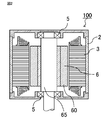
- FIGS. 1 and 2 are cross-sectional views showing a rotary electric machine according to the first embodiment.
- FIG. 1 shows a cross section perpendicular to the axial direction of the rotary electric machine 100
- FIG. 2 shows a cross section parallel to the axial direction of the rotary electric machine 100.
- the rotary electric machine 100 rotates with the motor frame 2, the cylindrical stator 3 fixed in the motor frame 2, and the outer peripheral surface facing the inner peripheral surface of the stator 3. It has a child 6.
- the stator 3 is formed by winding a stator winding 32 around a stator core 31.
- An insulating member for preventing electrical short-circuiting between the stator core 31 and the stator winding 32 is arranged, but it is omitted in FIG. 1.
- the stator winding 32 is composed of a group of three or more polyphase windings, and a predetermined current is sequentially applied to the windings of each phase according to the phase of the rotor 6 by using a control device (not shown). By doing so, the rotor 6 is rotated.
- the rotor 6 is arranged with a constant gap between the rotor 6 and the inner peripheral surface of the stator 3.
- the rotor 6 has a rotor core 60, a permanent magnet 8 and a rotating shaft 65, and the rotating shaft 65 is rotatably supported by a motor frame 2 via a bearing 5 on the axially outer side of the stator 3. ing.
- the rotor core 60 of the rotary electric machine 100 according to the first embodiment is arranged with an annular portion 61 fitted to the rotary shaft 65 on the innermost peripheral side and the outermost peripheral side, and the permanent magnet 8 is placed in the circumferential direction.
- Fan-shaped portion 62 has a fan-shaped portion 62 sandwiched from both side surfaces and a connecting portion 63 connecting the annular portion 61 and the fan-shaped portion 62. Further, the fan-shaped portion 62 constitutes a magnetic pole. Fan-shaped portions 62 are provided at intervals (voids) in the circumferential direction, and permanent magnets 8 are incorporated at every other place of the intervals (voids). Therefore, every other interval (void), which is half of those intervals (voids), serves as a magnet arrangement portion for arranging the permanent magnets 8. Therefore, the number of fan-shaped portions 62 is twice that of the permanent magnet 8.
- the magnetic poles of the permanent magnet 8 are perpendicular to the radial direction of the rotor 6, that is, the magnetic poles are directed in the tangential direction of the rotor 6, and each magnetic pole is magnetized in the same direction in the circumferential direction. Since the rotational torque generated in the rotor 6 is output to the outside via the rotary shaft 65, it is necessary to firmly fix the annular portion 61 and the rotary shaft 65 so as to withstand the rotary torque. As a fixing method, press-fitting, welding, or incorporating a detent key is used.
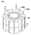
- FIG. 3 is a perspective view showing a laminated body of rotors according to the first embodiment.
- the laminated body 64 is formed by laminating a plurality of thin plates 66. Further, between the thin plates 66 of the laminated body 64, the thin plates 66 laminated in the axial direction are fixed to each other. Adjacent thin plates 66 are generally fixed by caulking, but may be fixed by welding or adhesion.
- the rotor core 60 of the rotary electric machine 100 is made of a thin plate 66 (generally a steel plate) made of a ferromagnetic material. It is formed by combining two laminated bodies 64 in which a large number of laminated bodies 64 are laminated. The two laminated bodies 64 have the same shape, and the rotor core 60 is formed by inverting each other in the axial direction and combining them.
- the laminated body 64 includes an annular portion 61, a fan-shaped portion 62, and a connecting portion 63, similarly to the rotor core 60.
- the rotor core 60 includes the same number of fan-shaped portions 62 as the magnetic poles of the rotor 6, but half of the fan-shaped portions 62 at every other location are one of the two laminated bodies 64. Included in.
- the fan-shaped portion 62 includes a first fan-shaped portion 62a supported by the annular portion 61 via the connecting portion 63, and a second fan-shaped portion 62b not connected to the annular portion 61 via the connecting portion 63. There is.
- the first fan-shaped portion 62a and the second fan-shaped portion 62b are each half the height of the rotor core 60. At this time, the first fan-shaped portion 62a is connected to the annular portion 61 via the connecting portion 63, but the second fan-shaped portion 62b is not directly connected to the connecting portion 63, and the plurality of thin plates 66 are laminated. It is formed by connecting them by connecting them.
- the connecting portion 63 on the inner diameter side is connected to the annular portion 61, and the other end on the outer diameter side is connected to the circumferential side surface of the first fan-shaped portion 62a.
- the first fan-shaped portion 62a has two circumferential side surfaces. Of those peripheral side surfaces, in FIG. 1, the other end of the connecting portion 63 on the outer diameter side is the side surface of the first fan-shaped portion 62a (permanent magnet 8 is arranged) on which the permanent magnet 8 is not arranged. It is connected to a portion (a portion other than the inner peripheral end) of the first fan-shaped portion 62a other than the surface) excluding the inner peripheral end.
- the torque of the rotary electric machine 100 is generated between the magnetic poles of the stator 3 and the rotor 6, and is taken out from the rotary shaft 65 to the outside. Therefore, since torque acts on the fan-shaped portion 62 with respect to the rotating shaft 65, the connecting portion 63 connecting the two must have strength to withstand the torque. Further, centrifugal force is generated in the fan-shaped portion 62 and the permanent magnet 8 during rotation, and it is necessary to support it by the connecting portion 63. In order for the connecting portion 63 to withstand these loads, it is desirable to make the connecting portion 63 short and thick. As described above, there is a trade-off relationship between the magnetically desirable shape and the mechanically desirable shape for the connecting portion 63.
- the assembly is connected to the annular portion 61 via the two connecting portions 63.
- the connecting portion 63 is arranged at the inner peripheral end of the fan-shaped portion 62, the distance between the two connecting portions 63 in the circumferential direction becomes the shortest and is structurally weak against torque. Must widen the circumferential width of the connecting portion 63. In this case, the connecting portion 63 becomes short and thick, which is not desirable in terms of leakage magnetic flux.
- the permanent magnets 8 are arranged between all the fan-shaped portions 62 adjacent in the circumferential direction, the place where the connecting portion 63 is arranged is only the inner peripheral end of the fan-shaped portion 62.
- the permanent magnets 8 are arranged at every other place between the fan-shaped portions 62, the permanent magnets 8 are arranged on the circumferential side surface of the fan-shaped portion 62.
- the connecting portion 63 can be arranged in addition to the inner peripheral end as long as it is in a plane that is not covered.
- the two connecting portions 63 connected to the assembly are compared with the case where the connecting portion 63 is arranged on the inner peripheral end. Since the circumferential distance becomes long, it becomes easy to withstand the torque and the connecting portion 63 can be made thin. Further, the length of the connecting portion 63 is also longer than that when the connecting portion 63 is arranged at the inner peripheral end. Therefore, the magnetic resistance of the connecting portion 63 can be increased as compared with the case where it is arranged at the inner peripheral end, and the leakage magnetic flux is reduced.
- the optimum position of the connecting portion 63 on the side surface of the fan-shaped portion 62 depends on the specifications of the rotary electric machine 100, the shape of the fan-shaped portion 62, and the like. It is possible to improve the characteristics by arranging it at the edge.
- FIGS. 4A to 4E are perspective views showing a process of assembling the rotor according to the first embodiment.
- the laminated structure of the thin plate 66 is omitted in order to avoid complicating the drawings.
- a first laminated body 64a which is a laminated body 64 having an annular portion 61, a fan-shaped portion 62, and a connecting portion 63, is prepared.
- the rotor core 60 is formed by combining the first laminated body 64a and the second laminated body 64b having the same shape as the first laminated body 64a.
- the first laminated body 64a and the second laminated body 64b include a first fan-shaped portion 62a and a second fan-shaped portion 62b, respectively.
- the permanent magnet 8 is attached to the first laminated body 64a.
- the same number of permanent magnets 8 as the fan-shaped portion 62 are arranged on a predetermined direction of the circumferential side surface of the fan-shaped portion 62 of the first laminated body 64a, here, on one side surface in the clockwise direction when viewed from the upper surface.
- an adhesive is applied to the permanent magnet 8 or the fan-shaped portion 62 in advance to bond the two.
- the permanent magnet 8 magnetized in advance may be used to fix both of them by utilizing the magnetic attraction force.
- the magnetic poles are oriented in the circumferential direction and the polarities of all the permanent magnets 8 are the same, as in the polarities of N and S shown in the figure.
- the side in contact with the first laminated body 64a is the N pole, but the polarities may be reversed as long as the directions of all the permanent magnets 8 are aligned.
- the second laminated body 64b After arranging the permanent magnet 8 on the first laminated body 64a, the second laminated body 64b is attached from the axial direction as shown in FIG. 4C. At this time, the position where the second laminated body 64b is rotated in the direction in which the arrangement space of the permanent magnet 8 is widened so that the fan-shaped portion 62 of the second laminated body 64b does not hit the permanent magnet 8 already arranged. Combine from the axial direction with. When the second laminated body 64b is moved in the axial direction, the annular portions 61 of the first laminated body 64a and the second laminated body 64b are in contact with each other in the axial direction, and the state shown in FIG. 4D is obtained.
- the annular portions 61 of the first laminated body 64a and the second laminated body 64b are arranged so as to be overlapped with each other so as to be adjacent to each other in the axial direction.
- the second laminated body 64b is moved in the direction of the arrow with respect to the first laminated body 64a so that the fan-shaped portion 62 of the second laminated body 64b is pressed against the permanent magnet 8. Rotate around the axis. As a result, both sides of the permanent magnet 8 in the circumferential direction are sandwiched between the fan-shaped portion 62 of the first laminated body 64a and the fan-shaped portion 62 of the second laminated body 64b. At this time, the space between the fan-shaped portion 62 of the second laminated body 64b and the permanent magnet 8 is also fixed by adhesion or magnetic attraction as in the case of the first laminated body 64a.
- FIG. 5 is a perspective view showing a modified example of the rotor according to the first embodiment.
- the permanent magnet 8 and the fan-shaped portion 62 are fixed by bonding the two, but as shown in FIG. 5, a magnet holding claw 67 is provided at the outer peripheral end of the fan-shaped portion 62.
- Permanent magnet 8 may be used for radial positioning, or for supporting centrifugal force acting on the permanent magnet 8 during operation of the rotary electric machine 100.
- FIG. 6 is a perspective view showing a rotor holding member according to the first embodiment.
- FIG. 7 is a perspective view showing a state in which the holding member is attached to the rotor according to the first embodiment.
- the rotation direction holding member 68 is provided between the adjacent fan-shaped portions 62, and is attached to the circumferential side surface of the fan-shaped portion 62 opposite to the one side surface in the circumferential direction in which the permanent magnet 8 is arranged. Be done.
- the rotation direction holding member 68 presses the bonding surface when the permanent magnet 8 and the fan-shaped portion 62 are bonded to each other.
- the rotation direction of the laminated bodies 64 which are the laminated bodies 64b, can be fixed.
- the rotation direction holding member 68 is made of a non-magnetic material and contains, for example, a resin or the like.
- the rotation direction holding member 68 may be arranged at intervals between the fan-shaped portions 62, or may be an integral part connected at one end in the axial direction as shown in FIG.
- the conventional structure there is also a problem that it is difficult to sufficiently apply the adhesive to the surface of the magnet and the facing surface of the iron core because the gap between the hole of the iron core and the magnet is small.
- the permanent magnet 8 and the rotor core 60 are bonded, the permanent magnet 8 is not inserted into the magnet arrangement portion, but is pressed in the direction of pressing the bonded surface.
- the permanent magnet 8 can be assembled. Therefore, it is possible to reduce the gap between the magnetic pole surface and the rotor core 60 as much as possible and to secure sufficient adhesive strength at the same time.
- the rotor 6 of the rotary electric machine 100 according to the first embodiment does not need to slide the permanent magnet 8 when the permanent magnet 8 is installed, so that the permanent magnet 8 is easy to install and the permanent magnet 8 is less likely to be damaged.
- the rotary electric machine 100 of the first embodiment is formed by laminating a plurality of thin plates 66, is supported by the annular portion 61 attached to the rotary shaft 65, and is supported by the annular portion 61, and is spaced apart in the circumferential direction.
- a first iron core having a first fan-shaped portion 62a arranged above the ground and a second fan-shaped portion 62b stacked on the first fan-shaped portion 62a and connected by connecting a plurality of thin plates 66, respectively.
- the second fan-shaped portion 62b of the first iron core and the first fan-shaped portion 62a of the second iron core are alternately arranged in the circumferential direction and are in the same plane because they are attached to the rotating shaft 65 so as to face each other.
- the permanent magnet 8 is supported by the annular portion 61 of the second iron core at every other place by the connecting portion 63 provided on the one side surface in the circumferential direction and the side surface in the circumferential direction opposite to the circumferential direction. be.
- a plurality of thin plates 66 are laminated and formed, and the annular portion 61 attached to the rotary shaft 65 and the annular portion 61 are supported and spaced apart from each other in the circumferential direction.
- a first iron core having a first fan-shaped portion 62a arranged above the ground and a second fan-shaped portion 62b stacked on top of the first fan-shaped portion 62a and connected by connecting a plurality of thin plates 66, respectively.
- step of preparing the second iron core the step of attaching the permanent magnet 8 to one side surface in the circumferential direction of the first fan-shaped portion 62a and the second fan-shaped portion 62b of the first iron core, and the step of attaching the second iron core to the second.
- a step of rotating the second iron core around the shaft and fixing the permanent magnet 8 to the first iron core and the second iron core is provided, and the second fan-shaped portion 62b and the second of the first iron core are provided.
- the first fan-shaped portion 62a of the iron core of No. 2 is provided at every other place in the same plane by the connecting portion 63 provided on the side surface in the circumferential direction opposite to the one side surface in the circumferential direction in which the permanent magnet 8 is arranged. It is supported by the annular portion 61 of the second iron core.
- the first iron core which is the first laminated body 64a and the second laminated body 64b are the first laminated body 64a while suppressing the damage of the permanent magnet 8. It is possible to obtain a rotary electric machine 100 and a method for manufacturing the rotary electric machine 100 in which the permanent magnet 8 can be fixed to the iron core of 2.
- Embodiment 2. 8A and 8B are perspective views showing a process of assembling the rotor according to the second embodiment.
- the rotary electric machine 100 according to the second embodiment will be described focusing on a portion different from the first embodiment.
- the first laminated body 64a and the second laminated body 64b each have an annular portion 61, a fan-shaped portion 62, and a connecting portion 63, and the fan-shaped portion 62 included therein has a rotor 6 respectively.
- the fact that the number of poles is half of that of the first embodiment is the same as that of the first embodiment.
- the configuration in which the fan-shaped portions 62 in contact with both sides of the permanent magnet 8 in the circumferential direction are members of different laminated bodies 64 is also the same as that of the first embodiment.
- the rotor core 60 is formed by two laminated bodies 64, but in the second embodiment, the rotor core 60 is formed by three or more laminated bodies 64.
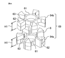
- the laminated body set 69 is formed by assembling the first laminated body 64a, the second laminated body 64b, and the permanent magnet 8 as described in the first embodiment.
- the height H1 of the fan-shaped portion 62 of the first laminated body 64a and the second laminated body 64b is 1 ⁇ 2 of the height of the rotor core 60.
- FIG. 8B shows the rotor 6 formed by arranging two sets of the laminated body sets 69 formed in FIG. 8A in the axial direction.
- the first laminated body 64a and the second laminated body 64b have a cross section perpendicular to the axis and have a shape symmetrical with respect to a cross section passing through the axial center of the rotor core 60.
- the height of one laminated body is set to half of the rotor core 60, and an example in which two laminated body sets 69 are arranged side by side is shown, but it is also possible to configure three or more sets.
- the permanent magnet 8 is divided into two in the axial direction according to each laminated body set 69, but it is also possible to reduce the number of parts by using one permanent magnet 8 without division. Is.
- a permanent magnet 8 having a length that matches the axial height of the entire rotor core 60 may be incorporated, or the axial length of one permanent magnet 8 may be set to the height of the laminated body set 69.
- permanent magnets 8 for the number of sets of laminated bodies may be arranged in the axial direction.
- 9A and 9B are perspective views showing a modified example of the rotor assembly process according to the second embodiment. In the above case, first, as shown in FIG.
- the first laminated body 64a and the second laminated body 64b are stacked in the axial direction in a state where the space in which the permanent magnet 8 is incorporated is widened.
- a permanent magnet 8 is attached to the side surface of every other fan-shaped portion 62. After that, it is formed by rotating the fan-shaped portion 62 that is not in contact with the permanent magnet 8 and pressing it against the permanent magnet 8.
- FIG. 10 is a perspective view showing a state in which a modified example of the rotor according to the second embodiment is disassembled.
- FIG. 10 describes an example in which the rotor core 60 is composed of three or more laminated bodies including laminated bodies having different shapes.
- the rotor core 60 is formed of a third laminated body 64c, a fourth laminated body 64d, and a fifth laminated body 64e.
- the elements (annular portion 61, fan-shaped portion 62, connecting portion 63) constituting each laminated body are the same as those of the laminated body 64 described in the first embodiment, but their heights are different. ..
- the fourth laminated body 64d the configuration of the fan-shaped portion 62 is different.
- the third laminated body 64c and the fifth laminated body 64e arranged at both ends in the axial direction have a cross section perpendicular to the axis and a symmetrical shape with respect to a cross section passing through the axial center of the rotor core 60.
- the fan-shaped portions 62 (range of H5) connected to the connecting portion 63 are located on both sides in the axial direction.
- H2 the height of the portion connected to the connecting portion 63 of the fan-shaped portion 62 included in the third laminated body 64c is H2 and the height of the portion connected only by laminating the fan-shaped portion 62 is H3, H2 and H4 Are equal, and H3 is half the height of H5.
- the third laminated body 64c and the fifth laminated body 64e are fitted and rotated from both sides in the axial direction to rotate the rotor 6. assemble. With such a configuration, it is possible to reduce the number of laminated bodies 64 while making the height of the portion of the fan-shaped portion 62 connected only by the stacking the same as the configuration described with reference to FIGS. 8 and 9. ..
- each fan-shaped portion 62 is connected to the annular portion 61 via the connecting portion 63, and the other half of the height portion is fan-shaped. It is connected only by laminating the portions 62.
- the height of the portion connected only by laminating the fan-shaped portions 62 also increases. As a result, it is possible that the strength may decrease or the straightness may decrease.
- the rotary electric machine 100 according to the second embodiment since the rotor core 60 is formed by three or more laminated bodies 64, the height of the fan-shaped portion 62 (for example, H1 in FIG.
- the assembly process such as incorporating the permanent magnet 8 or press-fitting into the rotating shaft 65 is a little complicated, but the permanent magnet 8 and the rotation
- the effects of ensuring the adhesive strength with the core 60 and reducing the gap between the permanent magnet 8 and the rotor core 60 can be obtained in the same manner as in the first embodiment.
- Embodiment 3. 11 and 12 are schematic cross-sectional views showing a laminate of rotors according to the third embodiment.
- the laminated body 64 having the annular portion 61, the fan-shaped portion 62, and the connecting portion 63 is the same as that described in the first embodiment.
- what is different from the first embodiment is the axial height of the annular portion 61 and the connecting portion 63.
- the axial height H6 of the annular portion 61 and the connecting portion 63 is the same, and is a value smaller than 1/2 of the height H7 of the fan-shaped portion 62.
- FIG. 12 shows a schematic cross-sectional view of a state in which two of the laminated bodies 64 are combined to form a rotor core 60.
- the height H6 of the annular portion 61 is lower than the height H7 of the fan-shaped portion 62, and the two laminated bodies 64 are assembled as the rotor core 60.
- the annular portion 61 does not come into contact with the axial direction, and the spacer 70 is arranged between them.
- the spacer 70 is a non-magnetic material, for example, a metal such as stainless steel or aluminum, or a resin, and is annular like the annular portion 61. Further, the spacer 70 may not be arranged and a gap corresponding to the thickness thereof may be provided.
- the rotor core 60 is formed of two laminated bodies 64, half of the fan-shaped portions 62 provided in the rotor core 60 are one laminated body 64 and the other half are the other. It is formed by the laminated body 64.
- all of the fan-shaped portions 62 provided have magnetic poles having the same polarity. Therefore, the fan-shaped portions 62 are magnetically connected to each other via the connecting portion 63 and the annular portion 61, but since they have the same poles, no leakage magnetic flux is generated via the above path, that is, the inside of the laminated body 64.
- the annular portion 61 has the same polarity as the fan-shaped portion 62 connected to the annular portion 61.
- the contact portions of the annular portions 61 have different polarities.
- a leakage magnetic flux is generated between the two.
- a non-magnetic spacer 70 or a gap is provided between these annular portions 61 to magnetically block the magnetic flux and reduce the leakage magnetic flux. Therefore, by using the rotor core 60 of the third embodiment, it is possible to improve the output of the rotary electric machine 100 or to reduce the size of the product with the same output.
Landscapes
- Engineering & Computer Science (AREA)
- Power Engineering (AREA)
- Manufacturing & Machinery (AREA)
- Iron Core Of Rotating Electric Machines (AREA)
- Permanent Field Magnets Of Synchronous Machinery (AREA)
- Manufacture Of Motors, Generators (AREA)
- Permanent Magnet Type Synchronous Machine (AREA)
Priority Applications (1)
| Application Number | Priority Date | Filing Date | Title |
|---|---|---|---|
| JP2022535281A JP7325645B2 (ja) | 2020-07-09 | 2021-07-01 | 回転電機および回転電機の製造方法 |
Applications Claiming Priority (2)
| Application Number | Priority Date | Filing Date | Title |
|---|---|---|---|
| JP2020118152 | 2020-07-09 | ||
| JP2020-118152 | 2020-07-09 |
Publications (1)
| Publication Number | Publication Date |
|---|---|
| WO2022009774A1 true WO2022009774A1 (ja) | 2022-01-13 |
Family
ID=79552545
Family Applications (1)
| Application Number | Title | Priority Date | Filing Date |
|---|---|---|---|
| PCT/JP2021/024954 Ceased WO2022009774A1 (ja) | 2020-07-09 | 2021-07-01 | 回転電機および回転電機の製造方法 |
Country Status (2)
| Country | Link |
|---|---|
| JP (1) | JP7325645B2 (https=) |
| WO (1) | WO2022009774A1 (https=) |
Cited By (1)
| Publication number | Priority date | Publication date | Assignee | Title |
|---|---|---|---|---|
| CN115800584A (zh) * | 2022-12-02 | 2023-03-14 | 珠海格力电器股份有限公司 | 转子组件、转子和电机 |
Citations (2)
| Publication number | Priority date | Publication date | Assignee | Title |
|---|---|---|---|---|
| WO2013175832A1 (ja) * | 2012-05-24 | 2013-11-28 | 三菱電機株式会社 | 回転電機の回転子、回転電機、回転電機の回転子の製造方法 |
| WO2018043288A1 (ja) * | 2016-09-05 | 2018-03-08 | 三菱電機株式会社 | 回転電機 |
-
2021
- 2021-07-01 WO PCT/JP2021/024954 patent/WO2022009774A1/ja not_active Ceased
- 2021-07-01 JP JP2022535281A patent/JP7325645B2/ja active Active
Patent Citations (2)
| Publication number | Priority date | Publication date | Assignee | Title |
|---|---|---|---|---|
| WO2013175832A1 (ja) * | 2012-05-24 | 2013-11-28 | 三菱電機株式会社 | 回転電機の回転子、回転電機、回転電機の回転子の製造方法 |
| WO2018043288A1 (ja) * | 2016-09-05 | 2018-03-08 | 三菱電機株式会社 | 回転電機 |
Cited By (1)
| Publication number | Priority date | Publication date | Assignee | Title |
|---|---|---|---|---|
| CN115800584A (zh) * | 2022-12-02 | 2023-03-14 | 珠海格力电器股份有限公司 | 转子组件、转子和电机 |
Also Published As
| Publication number | Publication date |
|---|---|
| JP7325645B2 (ja) | 2023-08-14 |
| JPWO2022009774A1 (https=) | 2022-01-13 |
Similar Documents
| Publication | Publication Date | Title |
|---|---|---|
| CN102570669B (zh) | 端板和用于旋转电机的使用该端板的转子 | |
| JP5128538B2 (ja) | アキシャルギャップ型回転電機 | |
| JP6599005B2 (ja) | コンシクエントポール型の回転子、電動機および空気調和機 | |
| CN103312065B (zh) | 具有永磁激励的转子,具有转子的电机和转子制造方法 | |
| JP6584331B2 (ja) | 単相ブラシレスモータおよび単相ブラシレスモータの製造方法 | |
| JP2009072009A (ja) | 永久磁石回転機 | |
| JP3137510B2 (ja) | 同期機の固定子,その製造方法並びにティース片及びヨーク片 | |
| JP4225091B2 (ja) | モータ用回転子 | |
| CN109643921B (zh) | 旋转电机 | |
| WO2016088200A1 (ja) | 回転電機用固定子コア、回転電機及び回転電機の製造方法 | |
| JP6545393B2 (ja) | コンシクエントポール型の回転子、電動機および空気調和機 | |
| JP2005269778A (ja) | アキシャルギャップ回転電機 | |
| WO2020067245A1 (ja) | ロータ、ロータの製造方法、モータ | |
| WO2018025407A1 (ja) | コンシクエントポール型の回転子、電動機および空気調和機 | |
| JP2019126102A (ja) | 回転子および回転電機 | |
| JPH11341719A (ja) | 電動機の回転子 | |
| JP2005333762A (ja) | 回転電機の回転子および回転電機 | |
| WO2022009774A1 (ja) | 回転電機および回転電機の製造方法 | |
| JP6824348B2 (ja) | 単相ブラシレスモータ、単相ブラシレスモータの製造方法、単相ブラシレスモータを備えた電気掃除機、および電気掃除機の製造方法 | |
| JP2012170231A (ja) | エンドプレート、およびこれを用いたシンクロナスリラクタンス型モータのロータ | |
| JP2006304532A (ja) | アキシャルギャップ型回転電機のロータ構造 | |
| JP7308645B2 (ja) | 回転電機 | |
| JP2005312124A (ja) | 回転電機の構造 | |
| US20240291341A1 (en) | Motor | |
| JP2015162996A (ja) | ブラシレスモータ |
Legal Events
| Date | Code | Title | Description |
|---|---|---|---|
| 121 | Ep: the epo has been informed by wipo that ep was designated in this application |
Ref document number: 21836858 Country of ref document: EP Kind code of ref document: A1 |
|
| ENP | Entry into the national phase |
Ref document number: 2022535281 Country of ref document: JP Kind code of ref document: A |
|
| NENP | Non-entry into the national phase |
Ref country code: DE |
|
| 122 | Ep: pct application non-entry in european phase |
Ref document number: 21836858 Country of ref document: EP Kind code of ref document: A1 |