WO2022009490A1 - 検査装置 - Google Patents
検査装置 Download PDFInfo
- Publication number
- WO2022009490A1 WO2022009490A1 PCT/JP2021/014771 JP2021014771W WO2022009490A1 WO 2022009490 A1 WO2022009490 A1 WO 2022009490A1 JP 2021014771 W JP2021014771 W JP 2021014771W WO 2022009490 A1 WO2022009490 A1 WO 2022009490A1
- Authority
- WO
- WIPO (PCT)
- Prior art keywords
- plate
- shaped member
- inspection device
- light
- unit
- Prior art date
- Legal status (The legal status is an assumption and is not a legal conclusion. Google has not performed a legal analysis and makes no representation as to the accuracy of the status listed.)
- Ceased
Links
Images








Classifications
-
- G—PHYSICS
- G01—MEASURING; TESTING
- G01N—INVESTIGATING OR ANALYSING MATERIALS BY DETERMINING THEIR CHEMICAL OR PHYSICAL PROPERTIES
- G01N21/00—Investigating or analysing materials by the use of optical means, i.e. using sub-millimetre waves, infrared, visible or ultraviolet light
- G01N21/84—Systems specially adapted for particular applications
-
- G—PHYSICS
- G01—MEASURING; TESTING
- G01N—INVESTIGATING OR ANALYSING MATERIALS BY DETERMINING THEIR CHEMICAL OR PHYSICAL PROPERTIES
- G01N21/00—Investigating or analysing materials by the use of optical means, i.e. using sub-millimetre waves, infrared, visible or ultraviolet light
- G01N21/84—Systems specially adapted for particular applications
- G01N21/88—Investigating the presence of flaws or contamination
- G01N21/95—Investigating the presence of flaws or contamination characterised by the material or shape of the object to be examined
- G01N21/958—Inspecting transparent materials or objects, e.g. windscreens
Definitions
- the present invention relates to an inspection device.
- a defect is inspected at an end portion.
- a line sensor and an illumination unit are used to photograph the end portion of the plate-shaped member, and the photographed image is inspected for the presence or absence of defects.
- An image for inspection is imaged while moving the line sensor and the illumination unit with respect to the end portion of the plate-shaped member, and the presence or absence of a defect is determined based on the captured image.
- the plate-shaped member is moved to inspect the other side.
- Patent Document 1 discloses a configuration in which a defect in the end face of a plate-shaped member is inspected by using a C-shaped ring illumination and two image pickup units. In this configuration, by moving the ring illumination and the imaging unit, each inspection point is photographed and a defect is inspected.
- Patent Document 2 light is obliquely incident on the plate-shaped member through a refracting body, and the end portion of the plate-shaped member irradiated with light that is totally reflected inside the plate-shaped member and travels is outside.
- the configuration for inspecting defects by observing from is disclosed. In this configuration, when the imaging unit is used, the plate-shaped member or the imaging unit is moved according to the size of the plate-shaped member to inspect the defect.
- the image pickup unit such as a line sensor has high resolution and detection capability
- the angle of view is narrow and the inspection range is limited.
- position accuracy with the end portion of the plate-shaped member is required in order to focus the imaging unit. Therefore, a moving mechanism, a focal length adjusting mechanism, and the like of the image pickup unit are required, which may lead to complicated, large-sized, and expensive inspection devices.
- An object of the present invention is to provide an inspection device capable of detecting defects in a plate-shaped member with a simple and inexpensive configuration.
- the inspection device is An inspection device that inspects defects in plate-shaped members.
- defects in the plate-shaped member can be detected with a simple and inexpensive configuration.
- FIG. 1 is a diagram showing an inspection device 1 according to an embodiment of the present invention.
- the inspection device 1 is a device for inspecting defects at the end of a plate-shaped member 2 made of a thin plate-shaped glass member used for a flat panel display mounted on, for example, an X-ray device. ..
- the inspection device 1 has a pedestal portion 10 and an illumination portion 20.
- Defects at the ends of the plate-shaped member 2 are fine, for example, when the plate-shaped member 2 is cut into a rectangular shape or the like from a strip-shaped glass plate manufactured by various manufacturing methods, and are generated on the cut surface at the time of cutting. It is a minute defect (inclined surface, concave surface, etc.) generated due to a defect, polishing of a cut portion, or the like. Further, the defect at the end of the plate-shaped member 2 is a defect generated due to an impact when the plate-shaped member 2 is dropped or the plate-shaped member 2 is hit against a wall or another member, for example. ..
- the pedestal portion 10 is a portion for arranging the plate-shaped member 2, and has a bottom portion 11, a plurality of contact portions 12, and a positioning portion 13 (see FIG. 2).
- the bottom portion 11 constitutes the bottom wall of the pedestal portion 10.
- the plurality of contact portions 12 are portions that protrude from the bottom portion 11 and come into contact with the plate-shaped member 2, and are provided over the arrangement range of the plate-shaped member 2 in the bottom portion 11. Each of the plurality of contact portions 12 comes into contact with the plate-shaped member 2 by point contact when the plate-shaped member 2 is arranged on the pedestal portion 10.
- the vertices of the plurality of contact portions 12 are arranged on a straight line (arrangement plane 10A) having substantially the same height position.
- the arrangement plane 10A is a plane that passes through each vertex position of the plurality of contact portions 12, which is a position where the plate-shaped member 2 is arranged in the pedestal portion 10. That is, the arrangement plane 10A is a plane having the same height position as the position where the plate-shaped member 2 is arranged in the pedestal portion 10.
- the positioning portion 13 is a portion for positioning for installing the plate-shaped member 2 on the pedestal portion 10, and is provided at a position corresponding to a predetermined end portion of the plate-shaped member 2 on the bottom portion 11.
- the positioning unit 13 has a first part 13A and a second part 13B.
- the predetermined end is, for example, an end corresponding to one of the four sides of the rectangular plate-shaped member 2. In FIG. 2, the predetermined end portion is exemplified by the lower end portion in FIG. 2 of the plate-shaped member 2.
- the first part 13A is provided at a position corresponding to a corner portion at a predetermined end portion of the plate-shaped member 2, and is formed in a substantially L-shape.
- positioning is performed on the pedestal portion 10 of the plate-shaped member 2, and the irradiation surface of the light L1 on the plate-shaped member 2 is aligned with the traveling direction of the light L1.
- the plate-shaped member 2 is installed so as to be vertical.
- the angle formed by the irradiation surface and the traveling direction is 90 degrees, and the irradiation surface is slightly deviated from 90 degrees.
- the second part 13B is provided at a position corresponding to a position other than the corner part at a predetermined end portion of the plate-shaped member 2.
- the first part 13A is provided at the left corner of the lower end of the plate-shaped member 2
- the second part 13B is provided at a position on the right side of the first part 13A. It is shown.
- the lighting unit 20 is a lighting device that irradiates the plate-shaped member 2 with light, and faces the side surface (irradiation surface) of the plate-shaped member 2 arranged on the pedestal portion 10. Have been placed.
- the illumination unit 20 extends in a predetermined direction, and is configured to be longer than the length of the side surface of the plate-shaped member 2 having the maximum size that can be arranged on the pedestal unit 10. As a result, the illumination unit 20 is configured to be able to irradiate the entire range of the irradiation surface (the surface facing the plate-shaped member 2) of the light L1 in the plate-shaped member 2 with the light L1.
- the illumination unit 20 is arranged to face the side surface of the plate-shaped member 2 arranged on the pedestal portion 10, and is in a traveling direction parallel to the arrangement plane 10A indicating the arrangement position of the plate-shaped member 2 on the pedestal portion 10. As described above, the plate-shaped member 2 is irradiated with light.
- the traveling direction parallel to the arrangement plane 10A includes not only the one completely parallel to the arrangement plane 10A but also the one slightly inclined with respect to the arrangement plane 10A.
- the lighting unit 20 irradiates the light L1 within a range corresponding to the thickness of the plate-shaped member 2. More specifically, the illumination unit 20 irradiates the light L1 within a range corresponding to the thickness of the portion (planar shape portion) in which the defect portion of the plate-shaped member 2 does not exist. The reason for this is that the illumination unit 20 passes the light L1 parallel to the upper surface and the lower surface of the plate-shaped member 2, so that the light L1 is emitted from the plate-shaped member 2 as it is when the plate-shaped member 2 has no defects. To observe.
- the thickness of the portion of the plate-shaped member 2 in which the defective portion does not exist is a thickness set based on the specifications of the plate-shaped member 2 and the like.
- the illumination unit 20 irradiates the plate-shaped member 2 with the light L1 parallel to the arrangement plane 10A, the light L1 enters the plate-shaped member 2 and travels in the plate-shaped member 2.
- the light L1 is incident on the plate-shaped member 2. It emits from the side surface opposite to the side.
- the upper surface 2A of the plate-shaped member 2 is visually observed from above the plate-shaped member 2 or the upper surface 2A of the plate-shaped member 2 is observed by an image pickup unit or the like, the upper surface 2A is not visible. That is, it can be observed that the light L1 is emitted from the plate-shaped member 2 as it is (there is no defect in the plate-shaped member 2).
- the plate-shaped member 2 when the end portion of the plate-shaped member 2 has a defective portion, that is, when the end portion of the upper surface 2A of the plate-shaped member 2 includes an inclined surface or a concave surface, the plate-shaped member 2 has a defective portion.
- the incident light L1 is diffused at the end portion.
- the inclined surface 2B inclined so as to be located downward as the end portion of the plate-shaped member toward the downstream side in the traveling direction of the light L1 is shown as a defect of the plate-shaped member 2.
- the traveling direction of the light L1 changes at the inclined surface 2B portion, and the diffused light L2 travels upward, for example.
- the defective portion on the upper surface 2A appears to shine, so that the defect is detected. It becomes.
- the illumination unit 20 irradiates the plate-shaped member 2 with light L1 so as to diffuse at the defective portion.
- the defect of the plate-shaped member 2 can be detected by observing from above the plate-shaped member 2 and the defective portion appears to shine, so that the defect can be detected visually or by a simple camera or the like.
- the image pickup unit can easily inspect the defect of the plate-shaped member 2.
- the defect of the plate-shaped member 2 can be easily inspected, it is not necessary to set the position of the imaging unit even when inspecting the plate-shaped member 2 having a different size. Therefore, the convenience of the inspection device 1 can be improved.
- the positioning portion 13 is provided on the pedestal portion 10, the light L1 can be incident on the plate-shaped member 2 at a desired position. As a result, when the plate-shaped member 2 has a defective portion, the diffused light L2 can be reliably generated and the defect can be inspected accurately.
- the lighting unit 20 can irradiate the entire range of the irradiation surface of the plate-shaped member 2 with the light L1, it is not necessary to arrange a plurality of lighting units side by side. That is, since the lighting unit 20 can be integrated into one, the structure of the inspection device 1 can be simplified.
- the inspection device 1 is composed of the pedestal portion 10 and the lighting portion 20, the plate-shaped member 2 can be inspected in a state where the plate-shaped member 2 is open. That is, since the pedestal portion 10 is installed so that the upper surface 2A (defect inspection surface) of the plate-shaped member 2 can be visually opened to the user, the plate-shaped member 2 can be easily opened without the need for an imaging unit. Can be inspected for defects.
- the plate-shaped member 2 is arranged on the plurality of contact portions 12, even if a foreign matter adheres to the pedestal portion 10, it is possible to prevent the plate-shaped member 2 from being scratched by the foreign matter.
- the illumination unit 20 irradiates the light L1 within the range corresponding to the thickness of the portion where the defective portion of the plate-shaped member 2 does not exist, it is possible to suppress the light L1 from passing above the plate-shaped member 2. can. As a result, it is possible to prevent the light L1 from being erroneously detected as the diffused light L2, so that the inspection accuracy of the inspection device 1 can be improved.
- the inspection device 1 has the pedestal portion 10 and the illumination unit 20, but the present invention is not limited to this, and as shown in FIG. 5, the inspection device 1 has the pedestal portion 10 and the pedestal portion 20.
- a shielding member 30 may be provided.
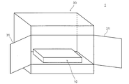
- the shielding member 30 is configured in a rectangular parallelepiped box shape, for example, and houses the pedestal portion 10 and the lighting portion 20 inside. That is, the shielding member 30 covers the pedestal portion 10 and the lighting portion 20.
- the shielding member 30 is provided with a door 31 on one side wall portion, and by opening the door 31, it is possible to arrange the plate-shaped member 2 on the pedestal portion 10 in the shielding member 30. Become.
- the upper surface of the plate-shaped member 2 becomes visible to the user. That is, the pedestal portion 10 is installed on the shielding member 30 so that the defect inspection surface of the plate-shaped member 2 can be visually opened by the user by opening the door 31.
- the shielding member 30 covers the pedestal portion 10 and the lighting portion 20, it is possible to prevent the reflection of the illumination light in the installation room of the inspection device 1 and improve the defect detection accuracy in the inspection device 1. can.
- a detection unit 40 capable of detecting an image related to the plate-shaped member 2 may be provided in the shielding member 30.
- the detection unit 40 is, for example, a CCD (Charge Coupled Device) camera.
- the detection unit 40 is provided on the upper wall 32 of the shielding member 30, and is arranged so that the entire plate-shaped member 2 arranged on the pedestal portion 10 can be imaged from the upper wall 32.
- the detection unit 40 can leave an image showing the state of the defect inspection surface in the plate-shaped member 2 as data, so that the convenience of inspecting the defect of the plate-shaped member 2 can be improved.
- the detection unit 40 can inspect the defect of the plate-shaped member 2 in a state where the shielding member 30 is sealed, the inspection accuracy in the inspection device 1 can be further improved.
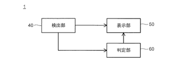
- the inspection device 1 may be provided with a display unit 50 connected to the detection unit 40.
- the display unit 50 is a display device such as a personal computer or a mobile terminal.
- the display unit 50 can confirm the state of defect inspection in the shielding member 30, so that the convenience of defect inspection in the inspection device 1 can be improved.
- it may have a determination unit 60 for determining the presence or absence of a defect in the plate-shaped member 2 based on the image detected by the detection unit 40.
- the determination unit 60 is a computer device such as a personal computer or a mobile terminal.
- the determination unit 60 includes a CPU (Central Processing Unit), a ROM (ReadOnlyMemory), a RAM (RandomAccessMemory), and an input / output circuit (not shown).
- the determination unit 60 controls the presence / absence of defects in the plate-shaped member 2 based on a preset program.
- the determination unit 60 acquires an image of the defect inspection surface of the plate-shaped member 2 and identifies the end portion of the plate-shaped member 2 to be determined. For example, as shown in FIG. 8, the determination unit 60 divides each of the four sides of the plate-shaped member 2 into three ranges. That is, the determination unit 60 divides each end of the plate-shaped member 2 into a total of 12 ranges. In FIG. 8, the range divided by the determination unit 60 is shown by a broken line.
- the determination unit 60 determines whether or not the diffused light L2 is generated in each of the 12 ranges. The determination unit 60 determines that the plate-shaped member 2 has a defective portion in the range where the diffused light L2 is generated, and the plate-shaped member 2 has a defective portion in the range where the diffused light L2 is not generated. Judge that it does not exist.
- the defective portion of the plate-shaped member 2 can be easily identified. Further, since the defect portion of the plate-shaped member 2 can be automatically determined, it is possible to suppress the variation in the inspection result due to the difference in the user's sense, and by extension, the convenience of the defect inspection in the inspection device 1. Can be improved.
- the determination unit 60 may cause the display unit 50 to display the determination result. For example, as shown in FIG. 9, when the end portion of the plate-shaped member 2 is divided into a total of 12 ranges, the determination unit 60 color-codes a portion having a defective portion and a portion having no defective portion. Is displayed on the display unit 50. That is, the display unit 50 displays the defect portion on the defect inspection surface of the plate-shaped member 2.
- FIG. 9 shows an example in which the portion where the defective portion is present is displayed in color and the portion where the defective portion is not present is displayed without color.
- the user can easily grasp the defective portion of the plate-shaped member 2 while checking the display unit 50.
- the number of detection units 40 is not mentioned, but two or more may be provided.
- the detection unit 40 it is necessary for the detection unit 40 to detect an image of the entire plate-shaped member 2.
- each detection unit 40 can be made inexpensive with a small number of pixels.
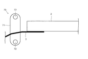
- the cable member 3 may be provided as shown in FIG. 10A.
- the cable member 3 may bend, which may interfere with the light L1 in the lighting unit 20.
- the light L1 interferes with the cable member 3
- the light L1 is diffused by the cable member 3 and may lead to erroneous detection of defects.
- the inspection device 1 may be provided with a regulation mechanism 70 that regulates the posture of the cable member 3.
- the regulation mechanism 70 has a moving unit 71 and a regulation unit 72.
- the moving portion 71 is configured to extend in the vertical direction, is outside the arrangement range of the plate-shaped member 2, and is on the downstream side of the downstream end portion of the plate-shaped member 2 in the traveling direction of the light L1. It is provided.
- the moving portion 71 is configured to be movably supported in a predetermined portion such as a pedestal portion 10 or a shielding member 30 of the inspection device 1 so as to be movable in the vertical direction, and is moved in the vertical direction by a known mechanism.
- the regulating portion 72 is provided at, for example, the upper end portion and the lower end portion of the moving portion 71, and extends from the moving portion 71 to a position corresponding to the arrangement range of the plate-shaped member 2.
- the plate-shaped member 2 is arranged in the inspection device 1 so that the cable member 3 is on the regulation mechanism 70 side.
- the cable member 3 is arranged at a position where it is sandwiched between the two restricting portions 72. Then, as shown in FIG. 10B, when the moving portion 71 is moved downward, the cable member 3 is pressed by the upper regulating portion 72. The moving portion 71 moves to a position where the upper regulating portion 72 is located below the plate-shaped member 2.
- the cable member 3 is surely deviated from the traveling direction of the light L1 incident on the plate-shaped member 2, so that it is possible to suppress erroneous detection of defects caused by the cable member 3.
- one lighting unit 20 is provided, but the present invention is not limited to this, and a plurality of lighting units 20 may be provided.
- a plurality of lighting units 20 may be provided so as to surround the plate-shaped member 2.
- each illuminating unit 20 sequentially irradiates the plate-shaped member 2 with light L1.
- the ends of the plate-shaped member 2 related to each side can be inspected without moving the plate-shaped member 2, so that the convenience of defect inspection in the inspection device 1 can be improved.
- the positioning portion 13 has a configuration in which a predetermined end portion of the plate-shaped member 2 is abutted against, but the present invention is not limited to this.
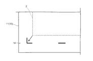
- a ruled line 14 or a laser marker 15 may be provided on the bottom 11 of the pedestal portion 10 to serve as a positioning portion. This makes it easier for the user to arrange the plate-shaped member 2 while looking at the ruled line 14 and the laser marker 15.
- the positioning unit has the first part and the second part, but the present invention is not limited to this, and for example, it is sufficient to have only the first part.
- the shape of the first part may be any shape as long as the plate-shaped member can be installed so that the light irradiation surface of the plate-shaped member is perpendicular to the traveling direction of the light.
- the plate-shaped member is configured in a rectangular shape, but the present invention is not limited to this, and may be a trapezoidal shape or a circular shape.
- the illumination unit 20 is configured to extend in a predetermined direction, but the present invention is not limited to this, and light can be vertically incident over the irradiation surface of the light in the plate-shaped member 2.
- any configuration may be used, for example, a configuration in which a light guide plate is provided.
- the pedestal portion 10 has a plurality of contact portions 12, but the present invention is not limited to this, and the pedestal portion 10 may not have a plurality of contact portions. Further, in the case of the configuration in which the plate-shaped member is arranged on the surface of the bottom portion of the pedestal portion, the position of the arrangement surface on the bottom portion is the arrangement plane.
- the defect of the end portion of the plate-shaped member 2 is mainly inspected, but the defect is not particularly limited to the end portion, and the defect of the entire surface of the plate-shaped member 2 is inspected. Is also good.
Landscapes
- Physics & Mathematics (AREA)
- Health & Medical Sciences (AREA)
- Life Sciences & Earth Sciences (AREA)
- Chemical & Material Sciences (AREA)
- Analytical Chemistry (AREA)
- Biochemistry (AREA)
- General Health & Medical Sciences (AREA)
- General Physics & Mathematics (AREA)
- Immunology (AREA)
- Pathology (AREA)
- Investigating Materials By The Use Of Optical Means Adapted For Particular Applications (AREA)
Abstract
検査装置は、板状部材の欠陥を検査する検査装置であって、板状部材を配置する台座部と、板状部材に欠陥部分が存在する場合、欠陥部分で拡散するように板状部材に光を照射する照明部と、を備える。
Description
本発明は、検査装置に関する。
従来、フラットパネルディスプレイ等に用いられる板状部材(例えば、板厚0.3mm~1.0mm程度のガラス薄板)においては、端部における欠陥の検査が行われる。このような検査としては、例えばラインセンサーおよび照明部を用いて板状部材の端部を撮影し、撮影した画像から欠陥の有無を検査する。板状部材の端部に対してラインセンサーおよび照明部を移動させつつ検査用の画像が撮像され、撮像された画像に基づいて欠陥の有無の判定が行われる。多角形状の板状部材では、一辺の検査が完了した後、板状部材を移動させて別の辺の検査が行われる。
例えば、特許文献1には、C字状のリング照明と2つの撮像部とを用いて板状部材の端面の欠陥を検査する構成が開示されている。この構成では、リング照明および撮像部を移動させることで、各検査箇所を撮影して欠陥の検査を行う。
また、特許文献2には、板状部材に斜めに光を、屈折体を介して入射して、板状部材内を全反射して進行する光により照射された板状部材の端部を外側から観察することで欠陥を検査する構成が開示されている。この構成では、撮像部を用いる場合、板状部材のサイズに合わせて板状部材または撮像部を移動させて欠陥の検査を行う。
しかしながら、ラインセンサー等の撮像部は解像度および検出能力が高い反面、画角が狭く検査範囲が限られる。また、撮像の際、撮像部の焦点を合わせるために板状部材の端部との位置精度が要求される。そのため、当該撮像部の移動機構や焦点距離調整機構等が必要となり、検査装置の複雑化、大型化、高額化につながるおそれがある。
本発明の目的は、簡素、かつ、安価な構成により板状部材の欠陥を検出することが可能な検査装置を提供することである。
本発明に係る検査装置は、
板状部材の欠陥を検査する検査装置であって、
前記板状部材を配置する台座部と、
前記板状部材に欠陥部分が存在する場合、前記欠陥部分で拡散するように前記板状部材に光を照射する照明部と、
を備える。
板状部材の欠陥を検査する検査装置であって、
前記板状部材を配置する台座部と、
前記板状部材に欠陥部分が存在する場合、前記欠陥部分で拡散するように前記板状部材に光を照射する照明部と、
を備える。
本発明によれば、簡素、かつ、安価な構成により板状部材の欠陥を検出することができる。
以下、本発明の実施の形態を図面に基づいて詳細に説明する。図1は、本発明の実施の形態に係る検査装置1を示す図である。
図1に示すように、検査装置1は、例えばレントゲン装置等に搭載されるフラットパネルディスプレイに用いられる薄板状のガラス部材で構成される板状部材2の端部の欠陥を検査する装置である。検査装置1は、台座部10と、照明部20とを有する。
板状部材2の端部の欠陥は、例えば、各種製造方法により製造された帯状のガラス板から、板状部材2が長方形状等に切断された際において、切断時に切断面において発生する微細な欠陥、切断部分の研磨加工等に起因して発生する微細な欠陥(傾斜面や凹面等)である。また、板状部材2の端部の欠陥は、例えば、板状部材2を落下させたり、板状部材2を壁や他の部材にぶつけたりした際の衝撃に起因して発生する欠陥である。
台座部10は、板状部材2を配置する部分であり、底部11と、複数の接触部12と、位置決め部13(図2参照)とを有する。底部11は、台座部10の底壁を構成する。
複数の接触部12は、底部11から突出して板状部材2と接触する部分であり、底部11における板状部材2の配置範囲にわたって設けられる。複数の接触部12のそれぞれは、板状部材2が台座部10に配置されると点接触により板状部材2と接触する。
そのため、複数の接触部12の各頂点は、略同一の高さ位置となる一直線(配置平面10A)上に並んでいる。配置平面10Aは、台座部10における板状部材2を配置する位置である、複数の接触部12の各頂点位置を通る平面である。つまり、配置平面10Aは、台座部10における板状部材2を配置する位置と同じ高さ位置となる平面である。
図2に示すように、位置決め部13は、台座部10に板状部材2を設置するための位置決めをする部分であり、底部11における板状部材2の所定の端部に対応する位置に設けられている。位置決め部13は、第1部13Aおよび第2部13Bを有する。所定の端部は、例えば、長方形状の板状部材2の4辺のうちの1辺に対応する端部である。図2では、所定の端部は、板状部材2の、図2における下側の端部が例示されている。
第1部13Aは、板状部材2の所定の端部における角部分に対応する位置に設けられ、略L字状に構成されている。板状部材2の当該角部分を第1部13Aに突き当てることで、板状部材2の台座部10における位置決めがなされ、板状部材2における光L1の照射面が、光L1の進行方向と垂直になるように、板状部材2が設置される。
なお、板状部材2における照射面が進行方向と垂直には、照射面と進行方向とのなす角度が90度のものの他、90度から微小角ずれたものも含まれる。
第2部13Bは、板状部材2の所定の端部における角部分以外に対応する位置に設けられる。図2では、第1部13Aは、板状部材2の下側の端部における、左側の角部に設けられ、第2部13Bは、第1部13Aよりも右側の位置に設けられた例が示されている。
第2部13Bを設けることで、板状部材2が第1部13Aに対応する角部を支点として回転することを抑制することができる。
図1および図3に示すように、照明部20は、板状部材2に光を照射する照明装置であり、台座部10に配置された板状部材2の側面(照射面)に対向して配置されている。照明部20は、所定方向に延びており、台座部10に配置可能な最大サイズの板状部材2の側面の長さよりも長く構成されている。これにより、照明部20は、板状部材2における光L1の照射面(板状部材2との対向面)の全範囲に光L1を照射可能に構成されている。
照明部20は、台座部10に配置された板状部材2の側面に対向して配置され、台座部10における板状部材2の配置位置を示す配置平面10Aに対して平行な進行方向となるように、光を板状部材2に照射する。
なお、配置平面10Aに対して平行な進行方向には、配置平面10Aと完全に平行なものの他、配置平面10Aに対して微小な角度傾斜したものも含む。
また、照明部20は、板状部材2の厚みに対応する範囲内に光L1を照射する。より詳細には、照明部20は、板状部材2の欠陥部分が存在しない部分(平面形状の部分)の厚みに対応する範囲内に光L1を照射する。この理由は、照明部20が板状部材2の上面および下面に平行に光L1を通すことにより、板状部材2に欠陥が存在しない場合に光L1がそのまま板状部材2から出射することを観察するためである。板状部材2の欠陥部分が存在しない部分の厚みは、その板状部材2の仕様等に基づいて設定される厚みである。
照明部20が板状部材2に配置平面10Aと平行な光L1を照射すると、光L1は、板状部材2に入射して、板状部材2内を進行する。ここで、板状部材2の端部に欠陥部分が存在しない場合、つまり、板状部材2の上面2Aが全体的に平面形状を維持している場合、光L1は、板状部材2の入射側とは反対側の側面から出射する。
そのため、例えば、板状部材2の上方から目視、または、撮像部等により、板状部材2の上面2Aを観察しても、上面2Aが光って見えない。つまり、光L1がそのまま板状部材2から出射すること(板状部材2に欠陥が存在しないこと)を観察することができる。
しかし、図4に示すように、板状部材2の端部に欠陥部分がある場合、つまり、板状部材2の上面2Aの端部が傾斜面や、凹面を含む場合、板状部材2に入射した光L1は、当該端部の部分で拡散する。図4に示す例では、板状部材の端部が光L1の進行方向における下流側に向かうにつれ、下に位置するように傾斜する傾斜面2Bが板状部材2の欠陥として示されている。
すなわち、板状部材2に傾斜面2B(欠陥部分)が存在すると、傾斜面2Bの部分で光L1の進行方向が変わって、例えば、上側へ進行する拡散光L2となる。これにより、板状部材2の上方から目視、または、撮像部等により板状部材2の上面2Aを観察すると、上面2Aにおける欠陥の部分が光って見えることとなるので、欠陥が検出されることとなる。言い換えると、照明部20は、板状部材2に欠陥部分が存在する場合、欠陥部分で拡散するように板状部材2に光L1を照射する。
ところで、ラインセンサー等を用いて、板状部材の端部毎に欠陥を検査する構成の場合、撮像の際、焦点を合わせるためにラインセンサーの位置を調整する必要が生じる。そのため、ラインセンサーと板状部材の端部との位置関係を調整するための移動機構や調整機構等が必要となり、検査装置の複雑化、大型化、高額化につながるおそれがある。
それに対し、本実施の形態では、板状部材2の上方から観察して、欠陥部分が光って見えることをもって板状部材2の欠陥を検出することができるので、目視や、カメラ等の簡易な撮像部によって板状部材2の欠陥の検査を容易に行うことができる。
すなわち、本実施の形態では、撮像部の移動機構や焦点距離調整機構等の複雑な機構を必要としないので、簡素、かつ、安価な構成により板状部材の欠陥を検出することができる。
また、板状部材2の欠陥の検査を容易に行うことができるので、サイズが異なる板状部材2の検査の際にも、撮像部の位置の設定をする必要がない。そのため、検査装置1における利便性を向上させることができる。
また、台座部10に位置決め部13が設けられているので、所望の位置において板状部材2に光L1を入射させることができる。その結果、板状部材2に欠陥部分が存在する場合、確実に拡散光L2を発生させて、欠陥の検査を正確に行うことができる。
また、照明部20が板状部材2の照射面の全範囲に光L1を照射可能であるので、複数の照明部を並べて配置する必要がなくなる。つまり、照明部20を一つとすることができるので、検査装置1の構造を簡素にすることができる。
また、検査装置1が台座部10および照明部20で構成されているので、板状部材2が開放された状態で板状部材2の検査を行うことができる。つまり、台座部10が、板状部材2の上面2A(欠陥検査面)を、ユーザーに目視可能に開放されるように設置されているので、撮像部を必要とせずに簡易に板状部材2の欠陥の検査を行うことができる。
また、複数の接触部12に、板状部材2を配置するので、台座部10に異物が付着したような場合でも、当該異物により板状部材2に傷がつくことを抑制することができる。
また、照明部20が板状部材2の欠陥部分が存在しない部分の厚みに対応する範囲内に光L1を照射するので、板状部材2の上方を光L1が通過することを抑制することができる。その結果、光L1が拡散光L2と誤検出されることを抑制することができるので、検査装置1の検査精度を向上させることができる。
なお、上記実施の形態では、検査装置1が台座部10および照明部20を有していたが、本発明はこれに限定されず、図5に示すように、検査装置1が台座部10および照明部20の他、遮蔽部材30を有していても良い。
遮蔽部材30は、例えば直方体状の箱型に構成されており、内部に台座部10および照明部20を収納する。つまり、遮蔽部材30は、台座部10および照明部20を覆っている。
遮蔽部材30には、例えば、1つの側壁部に扉31が設けられており、扉31を開放することで、遮蔽部材30内における台座部10上に板状部材2を配置することが可能となる。
また、扉31を開放することで、板状部材2の上面をユーザーが目視可能な状態となる。すなわち、遮蔽部材30には、扉31を開放することで、台座部10が、板状部材2の欠陥検査面を、ユーザーが目視可能に開放されるように設置されている。
これにより、ユーザーが簡易に板状部材2の欠陥の検査を行うことができる。
そして、遮蔽部材30が台座部10および照明部20を覆っているので、検査装置1の設置室における照明の光の映り込みを防止して、検査装置1における欠陥の検出精度を向上させることができる。
また、図6に示すように、遮蔽部材30内には、板状部材2に係る画像を検出可能な検出部40を設けても良い。検出部40は、例えばCCD(Charge Coupled Device)カメラである。検出部40は、遮蔽部材30における上壁32に設けられており、上壁32から、台座部10に配置された板状部材2全体を撮像可能に配置されている。
これにより、検出部40によって板状部材2における欠陥検査面の様子を示す画像をデータとして残すことができるので、板状部材2の欠陥の検査の利便性を向上させることができる。
また、検出部40により、遮蔽部材30を密閉した状態で、板状部材2の欠陥の検査を行うことができるので、検査装置1における検査精度をさらに向上させることができる。
また、図7に示すように、検査装置1において、検出部40に接続された表示部50が設けられていても良い。表示部50は、例えばパーソナルコンピューターや携帯端末等の表示装置である。
これにより、表示部50によって遮蔽部材30内における欠陥の検査の様子を確認することができるので、検査装置1における欠陥の検査の利便性を向上させることができる。
また、検出部40で検出した画像に基づいて板状部材2の欠陥の有無を判定する判定部60を有していても良い。
判定部60は、例えばパーソナルコンピューターや携帯端末等のコンピューター装置である。判定部60は、図示しないCPU(Central Processing Unit)、ROM(Read Only Memory)、RAM(Random Access Memory)および入出力回路を備えている。判定部60は、予め設定されたプログラムに基づいて板状部材2の欠陥の有無の判定制御を行う。
判定部60は、板状部材2の欠陥検査面の画像を取得して、判定対象となる板状部材2の端部を特定する。例えば、図8に示すように、判定部60は、板状部材2の4辺のそれぞれを3つの範囲に分割する。つまり、判定部60は、板状部材2の各端部を合計12個の範囲に分割する。図8には、判定部60により分割された範囲が破線で示されている。
そして、判定部60は、12個の範囲毎において、拡散光L2が発生しているか否かについて判定する。判定部60は、拡散光L2が発生している範囲については、板状部材2に欠陥部分が存在すると判定し、拡散光L2が発生していない範囲については、板状部材2に欠陥部分が存在しないと判定する。
このようにすることで、板状部材2の欠陥の箇所を容易に特定することができる。また、板状部材2の欠陥の箇所を自動で判定することができるので、ユーザーの感覚の違いに起因する検査結果のバラツキを抑制することができ、ひいては検査装置1における欠陥の検査の利便性を向上させることができる。
また、判定部60は、表示部50に判定結果を表示させるようにしても良い。例えば、図9に示すように、判定部60は、板状部材2の端部を合計12個の範囲に分割する場合、欠陥部分が存在する箇所と、欠陥部分が存在しない箇所とを色分けして表示部50に表示する。つまり、表示部50は、板状部材2の欠陥検査面において欠陥部分を特定する表示をする。図9には、欠陥部分が存在する箇所を色付きで表示し、欠陥部分が存在しない箇所を色なしで表示した例を示している。
こうすることで、ユーザーが表示部50を確認しながら、容易に板状部材2の欠陥の箇所を把握することができる。
また、図6等に示す構成では、検出部40の数については言及されていなかったが、2つ以上設けられていても良い。例えば、1つの検出部40が設けられた構成の場合、検出部40で、板状部材2全体の画像を検出する必要がある。
それに対して、例えば、検出部40を4つ設けて、板状部材2の、各検出部40に対応する範囲を検出するようにする。こうすることで、各検出部40を、画素数の少ない安価なものとすることができる。
ところで、フラットパネルディスプレイに用いられる板状部材2においては、図10Aに示すように、ケーブル部材3が設けられる場合がある。ケーブル部材3が設けられると、ケーブル部材3が屈曲することにより、照明部20における光L1の妨げになる可能性がある。光L1がケーブル部材3に干渉すると、光L1がケーブル部材3によって拡散されて、欠陥の誤検出につながるおそれがある。
そのため、検査装置1にケーブル部材3の姿勢を規制する規制機構70を設けても良い。規制機構70は、移動部71と、規制部72とを有する。
移動部71は、上下方向に延びて構成されており、板状部材2の配置範囲の外側であり、かつ、板状部材2の光L1の進行方向の下流側の端部よりも下流側に設けられている。移動部71は、検査装置1の台座部10や遮蔽部材30等の所定の部位に上下方向に移動可能に支持されて構成されており、公知の機構によって上下方向に移動する。
規制部72は、例えば、移動部71の上端部および下端部に設けられており、移動部71から、板状部材2の配置範囲に対応する位置まで延びている。
例えば、ケーブル部材3が規制機構70側になるように板状部材2を検査装置1に配置する。ケーブル部材3は、2つの規制部72に挟まれるような位置に配置する。そして、図10Bに示すように、移動部71を下方に移動させると、上側の規制部72によって、ケーブル部材3を押圧する。移動部71は、上側の規制部72が板状部材2より下の位置になる位置まで移動する。
これにより、ケーブル部材3が確実に板状部材2に入射された光L1の進行方向から外れるので、ケーブル部材3に起因する欠陥の誤検出を抑制することができる。
また、上記実施の形態では、1つの照明部20が設けられていたが、本発明はこれに限定されず、照明部20が複数設けられていても良い。例えば、図11に示すように、照明部20が、板状部材2を取り囲むように複数設けられていても良い。
照明部20は、板状部材2の4辺のそれぞれに対応して合計4つ設けられている。この構成では、各照明部20によって、順番に板状部材2に光L1を照射する。
こうすることで、板状部材2の各辺に係る端部を、板状部材2を動かさずに検査することができるので、検査装置1における欠陥の検査の利便性を向上させることができる。
また、上記実施の形態では、位置決め部13が、板状部材2の所定の端部が突き当てられる構成であったが、本発明はこれに限定されない。例えば、図12Aおよび図12Bに示すように、台座部10の底部11において罫書線14やレーザーマーカー15を設けて位置決め部としても良い。これにより、罫書線14やレーザーマーカー15を見ながらユーザーが板状部材2を配置しやすくすることができる。
また、上記実施の形態では、位置決め部が第1部および第2部を有していたが、本発明はこれに限定されず、例えば、第1部のみを有していれば良い。また、第1部の形状は、板状部材における光の照射面が光の進行方向と垂直になるように、板状部材を設置可能である限り、どのような形状であっても良い。
また、上記実施の形態では、板状部材が長方形状に構成されていたが、本発明はこれに限定されず、台形状でも良いし、円形状でも良い。
また、上記実施の形態では、照明部20が所定方向に延びて構成されていたが、本発明はこれに限定されず、板状部材2における光の照射面にわたって光を垂直に入射可能である限り、例えば導光板を設けた構成等、どのような構成であっても良い。
また、上記実施の形態では、台座部10が複数の接触部12を有していたが、本発明はこれに限定されず、複数の接触部を有していなくても良い。また、台座部の底部の面上に板状部材を配置する構成の場合、底部における配置面の位置が配置平面となる。
また、上記実施の形態では、主に板状部材2の端部の欠陥を検査していたが、特に端部の欠陥に限定されず、板状部材2の表面全体の欠陥の検査を行っても良い。
その他、上記実施の形態は、何れも本発明を実施するにあたっての具体化の一例を示したものに過ぎず、これらによって本発明の技術的範囲が限定的に解釈されてはならないものである。すなわち、本発明はその要旨、またはその主要な特徴から逸脱することなく、様々な形で実施することができる。
2020年7月7日出願の特願2020-116996の日本出願に含まれる明細書、図面および要約書の開示内容は、すべて本願に援用される。
1 検査装置
2 板状部材
3 ケーブル部材
10 台座部
10A 配置平面
11 底部
12 接触部
13 位置決め部
13A 第1部
13B 第2部
14 罫書線
15 レーザーマーカー
20 照明部
30 遮蔽部材
31 扉
32 上壁
40 検出部
50 表示部
60 判定部
70 規制機構
71 移動部
72 規制部
L1 光
L2 拡散光
2 板状部材
3 ケーブル部材
10 台座部
10A 配置平面
11 底部
12 接触部
13 位置決め部
13A 第1部
13B 第2部
14 罫書線
15 レーザーマーカー
20 照明部
30 遮蔽部材
31 扉
32 上壁
40 検出部
50 表示部
60 判定部
70 規制機構
71 移動部
72 規制部
L1 光
L2 拡散光
Claims (14)
- 板状部材の欠陥を検査する検査装置であって、
前記板状部材を配置する台座部と、
前記板状部材に欠陥部分が存在する場合、前記欠陥部分で拡散するように前記板状部材に光を照射する照明部と、
を備える検査装置。 - 前記照明部は、前記台座部における前記板状部材の配置位置を示す配置平面に対して平行な進行方向となるように、前記光を前記板状部材に照射する、
請求項1に記載の検査装置。 - 前記板状部材における前記光の照射面が前記光の前記進行方向と垂直になるように、前記板状部材を設置するための位置決め部を備える、
請求項2に記載の検査装置。 - 前記板状部材に設けられるケーブル部材の姿勢を規制する規制部を備える、
請求項1~3の何れか1項に記載の検査装置。 - 前記照明部は、前記板状部材における前記光の照射面の全範囲に前記光を照射可能に構成されている、
請求項1~4の何れか1項に記載の検査装置。 - 前記照明部は、前記板状部材を囲むように複数設けられている、
請求項1~5の何れか1項に記載の検査装置。 - 前記台座部は、前記板状部材の欠陥検査面を、ユーザーが目視可能に開放されるように設置されている、
請求項1~6の何れか1項に記載の検査装置。 - 前記板状部材の欠陥検査面の画像を検出する検出部を備える、
請求項1~7の何れか1項に記載の検査装置。 - 前記検出部により検出された画像を表示する表示部を備える、
請求項8に記載の検査装置。 - 前記表示部は、前記欠陥検査面において前記欠陥部分を特定する表示をする、
請求項9に記載の検査装置。 - 前記検出部は、前記欠陥検査面全体を検出可能なように、1つ以上設けられている、
請求項8~10の何れか1項に記載の検査装置。 - 前記画像に基づいて前記板状部材の欠陥の有無を判定する判定部を備える、
請求項8~11の何れか1項に記載の検査装置。 - 前記台座部および前記照明部を覆う遮光部材を備える、
請求項1~12の何れか1項に記載の検査装置。 - 前記照明部は、前記板状部材の前記欠陥部分が存在しない部分の厚みに対応する範囲内に前記光を照射する、
請求項1~13の何れか1項に記載の検査装置。
Applications Claiming Priority (2)
| Application Number | Priority Date | Filing Date | Title |
|---|---|---|---|
| JP2020-116996 | 2020-07-07 | ||
| JP2020116996 | 2020-07-07 |
Publications (1)
| Publication Number | Publication Date |
|---|---|
| WO2022009490A1 true WO2022009490A1 (ja) | 2022-01-13 |
Family
ID=79552868
Family Applications (1)
| Application Number | Title | Priority Date | Filing Date |
|---|---|---|---|
| PCT/JP2021/014771 Ceased WO2022009490A1 (ja) | 2020-07-07 | 2021-04-07 | 検査装置 |
Country Status (1)
| Country | Link |
|---|---|
| WO (1) | WO2022009490A1 (ja) |
Citations (5)
| Publication number | Priority date | Publication date | Assignee | Title |
|---|---|---|---|---|
| JP2003130814A (ja) * | 2001-10-23 | 2003-05-08 | Sharp Corp | 表示パネルの外観検査方法および外観検査装置 |
| JP2005156200A (ja) * | 2003-11-21 | 2005-06-16 | Nippon Electric Glass Co Ltd | 板ガラスの検査方法および板ガラスの検査装置 |
| CN104950492A (zh) * | 2015-07-09 | 2015-09-30 | 成都天奥测控技术有限公司 | 液晶显示屏缺陷自动检测系统 |
| CN109283197A (zh) * | 2018-08-27 | 2019-01-29 | 杭州元色科技有限公司 | 透明板材表面及内部瑕疵的检测方法及检测装置 |
| WO2020170389A1 (ja) * | 2019-02-21 | 2020-08-27 | 株式会社エフケー光学研究所 | 異物検査装置及び異物検査方法 |
-
2021
- 2021-04-07 WO PCT/JP2021/014771 patent/WO2022009490A1/ja not_active Ceased
Patent Citations (5)
| Publication number | Priority date | Publication date | Assignee | Title |
|---|---|---|---|---|
| JP2003130814A (ja) * | 2001-10-23 | 2003-05-08 | Sharp Corp | 表示パネルの外観検査方法および外観検査装置 |
| JP2005156200A (ja) * | 2003-11-21 | 2005-06-16 | Nippon Electric Glass Co Ltd | 板ガラスの検査方法および板ガラスの検査装置 |
| CN104950492A (zh) * | 2015-07-09 | 2015-09-30 | 成都天奥测控技术有限公司 | 液晶显示屏缺陷自动检测系统 |
| CN109283197A (zh) * | 2018-08-27 | 2019-01-29 | 杭州元色科技有限公司 | 透明板材表面及内部瑕疵的检测方法及检测装置 |
| WO2020170389A1 (ja) * | 2019-02-21 | 2020-08-27 | 株式会社エフケー光学研究所 | 異物検査装置及び異物検査方法 |
Similar Documents
| Publication | Publication Date | Title |
|---|---|---|
| KR101578496B1 (ko) | 이미지 센서의 틸트 결정 방법 | |
| KR20160004099A (ko) | 결함 검사 장치 | |
| JP2011117928A (ja) | 基板の内部欠陥検査装置および方法 | |
| WO2012120662A1 (ja) | ガラスびん検査装置及びテレセントリックレンズユニット | |
| JP4847128B2 (ja) | 表面欠陥検査装置 | |
| KR100565413B1 (ko) | 취성재료기판의 모서리 검사방법 및 그 장치 | |
| CN205562358U (zh) | 检验对象的系统 | |
| JP6829828B2 (ja) | レンズ外観検査装置 | |
| KR100898208B1 (ko) | 유리기판 검사장치 및 검사방법 | |
| WO2022009490A1 (ja) | 検査装置 | |
| JP7175214B2 (ja) | 検査装置 | |
| JP5100371B2 (ja) | ウェハ周縁端の異物検査方法、及び異物検査装置 | |
| JP2001124538A (ja) | 物体表面の欠陥検査方法および欠陥検査装置 | |
| CN219016120U (zh) | 一种检测装置 | |
| JP2006292412A (ja) | 表面検査装置、表面検査方法、及び基板の製造方法 | |
| JP6875243B2 (ja) | 板状体の検査装置 | |
| JP3078784B2 (ja) | 欠陥検査装置 | |
| JPH0518900A (ja) | レンズ欠陥検査方法及び検査装置 | |
| CN111007077A (zh) | 超薄板透明基板上表面异物检测装置 | |
| JPH0536726B2 (ja) | ||
| JP2821460B2 (ja) | 透明基板の傷検査装置 | |
| KR20220041388A (ko) | 광학계 교정 방법 | |
| TWI798586B (zh) | 物件缺陷之檢查方法及裝置 | |
| JP2003121385A (ja) | 石英ガラス材内部の欠陥検査方法および検査装置 | |
| JP7148181B1 (ja) | 検査治具及び検査方法 |
Legal Events
| Date | Code | Title | Description |
|---|---|---|---|
| 121 | Ep: the epo has been informed by wipo that ep was designated in this application |
Ref document number: 21838262 Country of ref document: EP Kind code of ref document: A1 |
|
| NENP | Non-entry into the national phase |
Ref country code: DE |
|
| 122 | Ep: pct application non-entry in european phase |
Ref document number: 21838262 Country of ref document: EP Kind code of ref document: A1 |
|
| NENP | Non-entry into the national phase |
Ref country code: JP |