WO2022009282A1 - 表示装置、作成装置、表示システムおよび表示方法 - Google Patents
表示装置、作成装置、表示システムおよび表示方法 Download PDFInfo
- Publication number
- WO2022009282A1 WO2022009282A1 PCT/JP2020/026458 JP2020026458W WO2022009282A1 WO 2022009282 A1 WO2022009282 A1 WO 2022009282A1 JP 2020026458 W JP2020026458 W JP 2020026458W WO 2022009282 A1 WO2022009282 A1 WO 2022009282A1
- Authority
- WO
- WIPO (PCT)
- Prior art keywords
- display
- icon
- equipment
- station
- display device
- Prior art date
- Legal status (The legal status is an assumption and is not a legal conclusion. Google has not performed a legal analysis and makes no representation as to the accuracy of the status listed.)
- Ceased
Links
Images





Classifications
-
- B—PERFORMING OPERATIONS; TRANSPORTING
- B61—RAILWAYS
- B61L—GUIDING RAILWAY TRAFFIC; ENSURING THE SAFETY OF RAILWAY TRAFFIC
- B61L25/00—Recording or indicating positions or identities of vehicles or trains or setting of track apparatus
- B61L25/02—Indicating or recording positions or identities of vehicles or trains
Definitions
- This disclosure relates to a display device, a creation device, a display system, and a display method mounted on a train.
- Patent Document 1 discloses a technique in which each display device specifies an installation position in each vehicle forming a train and changes the display content depending on the installation position.
- the present disclosure has been made in view of the above, and obtains a display device that displays information on necessary equipment while using common display contents and can change the display contents depending on the installation position in the train.
- the purpose is.
- the present disclosure is a display device mounted on a train.
- the display device was created for each station, and icons for each equipment including type information indicating the type of equipment installed at the station and location information indicating the location of the equipment at the station were placed at the position of each equipment with respect to the station.
- a first display area based on the installation position of the display device in the train is extracted from the storage unit that stores the display content and the display content of the station to be displayed stored in the storage unit, and is included in the display content.
- the first icon for the equipment included in the first display area is displayed based on the position arranged in the display content, and the second icon for the equipment not included in the first display area is displayed.
- a display control unit that controls display at the display end of the first display area and generates a second display area, and a display unit that displays a second display area generated by the display control unit are provided. It is characterized by.
- the display device has the effect of displaying information on necessary equipment while using common display contents, and changing the display contents depending on the installation position in the train.
- FIG. 2 shows an example of a second display area generated by the display control unit of the display device according to the present embodiment and displayed by the display unit.
- FIG. 3 shows an example of a second display area generated by the display control unit of the display device according to the present embodiment and displayed by the display unit.
- the figure which shows the example of the case where the processing circuit provided in the display device which concerns on this embodiment is configured by the dedicated hardware.
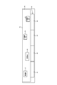
- FIG. 1 is a diagram showing a configuration example of the display system 30 according to the present embodiment.
- the display system 30 includes a creation device 10 and a display device 20.
- the creating device 10 includes information on equipment installed at a station (not shown), and creates display content for the station used by the display device 20 mounted on a train (not shown).
- the display device 20 is mounted on a train (not shown), and uses display contents acquired from the creation device 10 to display information such as the position of equipment installed at the next stop station to passengers in the train. ..
- the equipment is, for example, an elevator, an escalator, a staircase, a ticket gate, a toilet, etc., but is an example and is not limited thereto.
- Equipment includes at least one of elevators, escalators, stairs, ticket gates, and toilets.
- the display device 20 is installed around the door of each vehicle constituting the train. In the following description, it is assumed that the display device 20 is installed on the upper part of the door provided in each vehicle constituting the train. The display device 20 may be installed next to the door. The display device 20 changes the display content according to the installation position in the train in the traveling direction of the train, and displays information such as the position of the equipment of the next stop station.
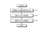
- FIG. 2 is a flowchart showing the operation of the creating device 10 according to the present embodiment.
- the operation receiving unit 11 receives an operation from an operator (step S11).
- the operation reception unit 11 is, for example, a mouse, a keyboard, or the like.
- the creation unit 12 arranges the equipment icon on the display content of the station based on the operation from the worker received by the operation reception unit 11, the type information indicating the type of the equipment and the equipment at the station are displayed on the icon.
- the display content is created by including the position information indicating the position of (step S12).
- the distribution unit 13 distributes the display content created by the creation unit 12 to the display device 20 mounted on the train (step S13).
- FIG. 3 is a diagram showing an example of display content 50 created by the creation device 10 according to the present embodiment.
- the display content 50 shown in FIG. 3 shows an example of arrangement of equipment at a station 45 where the train 40 on which the display device 20 is mounted stops.
- the train 40 on which the display device 20 is mounted is a 4-car train composed of vehicles 41 to 44.
- the display content 50 includes the train 40, but if the positional relationship between the station 45 with respect to the train 40, specifically, each facility on the platform can be grasped, the display content 50 includes the train 40. May not be included. As shown in FIG.
- the display content 50 includes an icon 51 for equipment # 1, an icon 52 for equipment # 2, an icon 53 for equipment # 3, and an icon 54 for equipment # 4. ..
- the icons 51 to 54 include type information indicating the type of equipment targeted by each icon, and position information indicating the position of the equipment at the station 45.
- the creating unit 12 uses the specified position of the station 45 as a reference.
- the coordinates of the equipment are included in each icon 51 to 54 as the position information of the equipment.
- the creation unit 12 arranges the icon 51 based on the above-mentioned reference.
- the two-dimensional XY coordinates of the determined position are calculated, and the calculated XY coordinates are included in the icon 51 as the position coordinates of the equipment # 1 targeted by the icon 51.
- the creating unit 12 includes the position information of the equipments # 2 to # 4 in the corresponding icons 52 to 54 in the same manner for the other icons 52 to 54.
- the creation unit 12 receives input from the operator via the operation reception unit 11 for the type information to be included in each of the icons 51 to 54, and includes the type information included in each of the icons 51 to 54 as text information.
- the creation unit 12 may receive text information from the operator via the operation reception unit 11 before or after arranging the icons 51 to 54 in the display content 50.
- the creation unit 12 receives the operation of the operator via the operation reception unit 11 and creates the display content 50 for each station 45 to be displayed by the display device 20.
- the creating unit 12 creates the display content 50 for each station 45 to be displayed, but creates one display content 50 for one station 45. Is.
- the distribution unit 13 distributes the display content 50 created by the creation unit 12 to the display device 20 by wireless communication.
- the distribution unit 13 distributes the display content 50 created for each station 45 by the creation unit 12 to the display device 20 by wireless communication.
- the distribution unit 13 may distribute the display content 50 while the train 40 is stopped in a garage or the like, or may distribute the display content 50 while the train 40 is running.
- the distribution unit 13 may distribute the display content 50 via wired communication, a storage medium, or the like.
- the timing at which the creating device 10 creates the display content 50 at the station 45 is not limited to the timing at which the operation of the station 45 is started.
- the creation device 10 can be used by a worker as appropriate, such as when the equipment of the station 45 is added, the position of the equipment of the station 45 is changed, or the construction is performed at the station 45 and the equipment is temporarily changed. The operation of is received, the display content 50 is created, and the display content 50 is distributed.
- the display device 20 includes an acquisition unit 21, a storage unit 22, a display control unit 23, and a display unit 24.
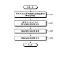
- FIG. 4 is a first flowchart showing the operation of the display device 20 according to the present embodiment.
- FIG. 5 is a second flowchart showing the operation of the display device 20 according to the present embodiment.
- the acquisition unit 21 acquires the display content 50 from the creation device 10 that creates the display content 50 by wireless communication (step S21).
- the acquisition unit 21 acquires the display content 50 created for each station 45 by the creation device 10 from the creation device 10 by wireless communication.
- the acquisition unit 21 may acquire the display content 50 while the train 40 is stopped in a garage or the like, or may acquire the display content 50 while the train 40 is traveling.
- the acquisition unit 21 may acquire the display content 50 via wired communication, a storage medium, or the like.
- the acquisition unit 21 stores the display content 50 acquired from the creation device 10 in the storage unit 22 (step S22).
- the acquisition unit 21 stores the display content 50 created for each station 45 by the creation device 10 in the storage unit 22.
- the storage unit 22 stores the display content 50 created by the creation device 10 and acquired by the acquisition unit 21 (step S22). When there are a plurality of stations 45 to be displayed by the display device 20, the storage unit 22 stores the display content 50 for each station 45 created by the creation device 10 for each station 45 and acquired by the acquisition unit 21.
- the display device 20 performs the operation of the flowchart shown in FIG. 4 every time the display content 50 of the new display target station 45 is acquired or the acquired display content 50 of the display target station 45 is updated.
- the display control unit 23 When the train 40 is started, the display control unit 23 outputs information on the installation position of the display device 20 in the train 40 in the traveling direction of the train 40 based on the identification information of the doors around which the display device 20 is installed. Acquire (step S31). The display control unit 23 displays a first display area based on the installation position of the display device 20 in the train 40 in the traveling direction of the train 40 from the display content 50 of the station 45 to be displayed stored in the storage unit 22. Extract (step S32). As a result, the display control unit 23 starts the train 40 even when the formation of the train 40 is changed and the number of vehicles of the train 40, the relative installation position of the display device 20 in the train 40, and the like are changed.
- the display control unit 23 It is possible to grasp the installation position of the display device 20 in the train 40 for each train. Further, it is assumed that the display control unit 23 holds information on the stop position of each train 40 for each station 45 to be displayed. As a result, the display control unit 23 recognizes which area should be extracted as the first display area from the display content 50 even when the relative installation position of the display device 20 in the train 40 is changed. be able to.
- the display control unit 23 displays the first icon, which is an icon for the equipment included in the first display area, among the icons included in the display content 50, based on the position arranged in the display content 50. Control is performed to display a second icon, which is an icon for equipment not included in the display area 1, at the display end of the first display area, and a second display area is generated (step S33).
- the display unit 24 displays the second display area generated by the display control unit 23 (step S34).
- the display device 20 performs the operation of the flowchart shown in FIG. 5 every time the train 40 starts, that is, every time the train 40 starts operating.
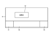
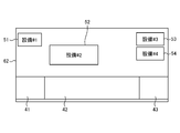
- FIG. 6 is a first diagram showing an example of a first display area 61 extracted by the display control unit 23 of the display device 20 according to the present embodiment.
- FIG. 7 is a first diagram showing an example of a second display area 62 generated by the display control unit 23 of the display device 20 according to the present embodiment and displayed by the display unit 24. 6 and 7 show an image of the operation of the display device 20 installed on the upper part of the door in the middle of the vehicle 42, in which the vehicles 41 to 44 of the train 40 have a configuration of three doors on each side.
- FIG. 7 shows an example of a second display area 62, that is, a display screen, which is displayed by the display device 20 installed on the upper part of the door in the middle of the vehicle 42.
- the display control unit 23 installs the display device 20 in the train 40 from the display content 50 of the station 45 to be displayed, as described above.
- the first display area 61 based on the position is extracted.
- the range of the first display area 61 extracted from the display content 50 by the display control unit 23 may be a fixed range defined in advance, depending on the number of icons included in the display content 50 and the like. It may be in a range of change.
- the display control unit 23 extracts a first display area 61 including a range defined from the door in the middle of the vehicle 42 from the display content 50.
- the first display area 61 includes the icon 52 of the equipment # 2, but does not include the icon 51 of the equipment # 1, the icon 53 of the equipment # 3, and the icon 54 of the equipment # 4. In this case, the passenger in the vehicle 42 cannot grasp the positions of the equipment # 1, the equipment # 3, and the equipment # 4 even by looking at the first display area 61.
- the display control unit 23 sets the icons 51, 53, 54 for the equipment # 1, the equipment # 3, and the equipment # 4 which are not included in the first display area 61 as the first display area. Control to display at the display end of 61 is performed. Specifically, the display control unit 23 displays the icon 51 of the equipment # 1 at the left end of the first display area 61, and displays the icon 53 of the equipment # 3 and the icon 54 of the equipment # 4 in the first display area. Control to display at the right end of 61. As a result, the display control unit 23 generates the second display area 62. The display control unit 23 outputs the generated second display area 62 to the display unit 24. The display unit 24 displays the second display area 62 generated by the display control unit 23. As a result, the passenger in the vehicle 42 can grasp the positions of the equipment # 1, the equipment # 3, and the equipment # 4 by looking at the second display area 62 displayed on the display unit 24.
- the positions of the icons 51 to 54 do not overlap in the state of the second display area 62 shown in FIG. 7, but when the icon 52 is slightly on the left side in the display content 50, the icon 51 And the icon 52 may overlap. Therefore, when the display control unit 23 does not have a space for displaying the icon 51 on the left side of the icon 52, the display control unit 23 shifts the position of the icon 52 slightly to the right to secure a space for displaying the icon 51, and secures a space for displaying the icon 51. 62 is generated.
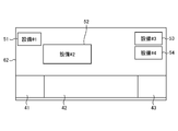
- FIG. 8 is a second diagram showing an example of a first display area 61 extracted by the display control unit 23 of the display device 20 according to the present embodiment.
- FIG. 9 is a second diagram showing an example of a second display area 62 generated by the display control unit 23 of the display device 20 according to the present embodiment and displayed by the display unit 24.
- the icon 52 of the equipment # 2 is located at a position overlapping with the icon 51 of the equipment # 1 in the second display area 62. Therefore, as shown in FIG.
- the display control unit 23 shifts the icon 52 slightly to the right from the position displayed in the first display area 61 to secure a space for displaying the icon 51, and the second display control unit 23 secures a space for displaying the icon 51.
- the display control unit 23 displays the position of the first icon in the second display area 62 without changing the position. Control to do.
- the display control unit 23 controls to change and display the position of the first icon in the second display area 62.
- the display control unit 23 displays the second icon not included in the first display area 61 at the display end to generate the second display area 62, the display control unit 23 displays the number of the second icons at the left end or the right end. If the number of icons increases, it is assumed that even if the position of the first icon is shifted, a part of the second icon cannot be displayed.
- the display control unit 23 is one for each type of equipment. Control may be performed to display all the icons together.
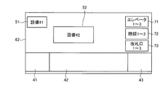
- FIG. 10 is a third diagram showing an example of a second display area 62 generated by the display control unit 23 of the display device 20 according to the present embodiment and displayed by the display unit 24.
- the display control unit 23 controls to combine the icons into one icon for each elevator, each staircase, and each ticket gate, and edit and display the text information included in each icon.
- FIG. 10 is a third diagram showing an example of a second display area 62 generated by the display control unit 23 of the display device 20 according to the present embodiment and displayed by the display unit 24.
- the display control unit 23 collectively combines the icons of a plurality of elevators into one icon 71, the icons of a plurality of stairs into one icon 72, and the icons of a plurality of ticket gates collectively 1 There are two icons 73. Further, the display control unit 23 edits the text information included in the original icon of each equipment for each of the icons 71 to 73.
- the above-mentioned threshold value may be defined in advance by, for example, the display size of the second display area 62 that can be displayed by the display unit 24 of the display device 20, but is not limited thereto.
- the acquisition unit 21 is a communication device.
- the storage unit 22 is a memory.
- the display unit 24 is a monitor such as an LCD (Liquid Crystal Display).
- the display control unit 23 is realized by a processing circuit.
- the processing circuit may be a processor and memory for executing a program stored in the memory, or may be dedicated hardware.
- FIG. 11 is a diagram showing an example in which the processing circuit included in the display device 20 according to the present embodiment is configured by a processor and a memory.
- the processing circuit is composed of the processor 91 and the memory 92, each function of the processing circuit of the display device 20 is realized by software, firmware, or a combination of software and firmware.
- the software or firmware is written as a program and stored in the memory 92.
- each function is realized by the processor 91 reading and executing the program stored in the memory 92. That is, the processing circuit includes a memory 92 for storing a program in which the processing of the display device 20 is to be executed as a result. It can also be said that these programs cause a computer to execute the procedure and method of the display device 20.
- the processor 91 may be a CPU (Central Processing Unit), a processing device, an arithmetic unit, a microprocessor, a microcomputer, a DSP (Digital Signal Processor), or the like.
- the memory 92 includes, for example, non-volatile or volatile such as RAM (Random Access Memory), ROM (Read Only Memory), flash memory, EPROM (Erasable Programmable ROM), EEPROM (registered trademark) (Electrically EPROM). This includes semiconductor memory, magnetic disk, flexible disk, optical disk, compact disk, mini disk, DVD (Digital Versatile Disc), etc.
- FIG. 12 is a diagram showing an example in which the processing circuit included in the display device 20 according to the present embodiment is configured by dedicated hardware.
- the processing circuit is composed of dedicated hardware
- the processing circuit 93 shown in FIG. 12 may be, for example, a single circuit, a composite circuit, a programmed processor, a parallel programmed processor, an ASIC (Application Specific Integrated Circuit), or the like. FPGA (Field Programmable Gate Array) or a combination of these is applicable.
- Each function of the display device 20 may be realized by the processing circuit 93 for each function, or each function may be collectively realized by the processing circuit 93.
- the functions of the display device 20 may be realized by dedicated hardware, and some may be realized by software or firmware.
- the processing circuit can realize each of the above-mentioned functions by the dedicated hardware, software, firmware, or a combination thereof.
- the operation receiving unit 11 is an interface device such as a mouse and a keyboard.
- the distribution unit 13 is a communication device.
- the creating unit 12 is realized by a processing circuit. As in the case of the display device 20, the processing circuit may be a processor and a memory for executing a program stored in the memory, or may be dedicated hardware.
- the display device 20 uses the common display content 50 created for each station 45 by the creation device 10 in the train 40 in the traveling direction of the train 40.
- the first display area 61 is extracted from the display content 50 based on the installation position of the display device 20, and the second icon not included in the first display area 61 is displayed at the left end or the right end of the first display area 61.
- the second display area 62 was generated and displayed in this way.
- each of the display devices 20 mounted on the train 40 displays the equipment information of the station 45 with different display contents according to the installation position of the display device 20 in the train 40 without leaking the equipment information. Can be displayed.
- the display device 20 can display information on necessary equipment while using the common display content 50, and can change the display content depending on the installation position in the train 40.
- the creating device 10 since the display device 20 can display the equipment information with one display content 50 for one station 45, the creating device 10 does not need to individually create the display content 50 for each installation position of the display device 20. , It is possible to suppress the trouble of creating the display content 50. Further, since the creating device 10 only needs to create one display content 50 for one station 45, it is possible to suppress the amount of data when the created display content 50 is distributed to the display device 20.
- the configuration shown in the above embodiments is an example, and can be combined with another known technique, can be combined with each other, and does not deviate from the gist. It is also possible to omit or change a part of the configuration.
- 10 creation device 11 operation reception section, 12 creation section, 13 distribution section, 20 display device, 21 acquisition section, 22 storage section, 23 display control section, 24 display section, 30 display system, 40 trains, 41-44 vehicles, 45 stations, 50 display contents, 51-54, 71-73 icons, 61 first display area, 62 second display area.
Landscapes
- Engineering & Computer Science (AREA)
- Mechanical Engineering (AREA)
- Train Traffic Observation, Control, And Security (AREA)
Abstract
列車に搭載される表示装置(20)であって、駅ごとに作成され、駅に設置される設備の種別を示す種別情報および駅での設備の位置を示す位置情報を含む設備ごとのアイコンが駅に対する各設備の位置に配置された表示コンテンツを記憶する記憶部(22)と、記憶部(22)に記憶されている表示対象の駅の表示コンテンツから、列車内での表示装置(20)の設置位置に基づく第1の表示領域を抽出し、表示コンテンツに含まれるアイコンのうち、第1の表示領域に含まれる設備についての第1のアイコンを表示コンテンツに配置された位置に基づいて表示し、第1の表示領域に含まれない設備についての第2のアイコンを第1の表示領域の表示端に表示する制御を行い、第2の表示領域を生成する表示制御部(23)と、表示制御部(23)で生成された第2の表示領域を表示する表示部(24)と、を備える。
Description
本開示は、列車に搭載される表示装置、作成装置、表示システムおよび表示方法に関する。
従来、列車は、列車を構成する各車両のドアの上部などに表示装置を設置し、表示装置が、次に停車する駅のエレベータ、階段などの設備の位置の情報を表示して、乗客に駅の設備の案内をしている。しかしながら、列車の編成によっては、車両の位置によって各設備の相対的な位置が異なる。このような問題に対して、特許文献1には、各表示装置が、列車を編成する各車両内での設置位置を特定し、設置位置によって表示内容を変更する技術が開示されている。
しかしながら、上記従来の技術によれば、各表示装置が表示する表示情報をどのように作成するのかについては記載されていない。例えば、各車両が片側に4つのドアを備える10両編成の列車の場合、4×10=40パターンの表示情報が必要となる。そのため、駅ごとに各表示装置の設置位置に応じて多くの表示情報を個別に作成し、各表示装置に個別に配信する方法では、作成および配信に手間がかかる、という問題があった。他の方法として、共通の表示コンテンツを用いて、各表示装置が設置位置に応じて表示領域を切り取って表示する方法が考えられる。しかしながら、各表示装置は、切り取った表示領域以外の設備の情報を表示できないため、必要な設備の情報を表示できない場合がある、という問題があった。
本開示は、上記に鑑みてなされたものであって、共通の表示コンテンツを使用しつつ、必要な設備の情報を表示し、列車内での設置位置によって表示内容を変更可能な表示装置を得ることを目的とする。
上述した課題を解決し、目的を達成するために、本開示は、列車に搭載される表示装置である。表示装置は、駅ごとに作成され、駅に設置される設備の種別を示す種別情報および駅での設備の位置を示す位置情報を含む設備ごとのアイコンが駅に対する各設備の位置に配置された表示コンテンツを記憶する記憶部と、記憶部に記憶されている表示対象の駅の表示コンテンツから、列車内での表示装置の設置位置に基づく第1の表示領域を抽出し、表示コンテンツに含まれるアイコンのうち、第1の表示領域に含まれる設備についての第1のアイコンを表示コンテンツに配置された位置に基づいて表示し、第1の表示領域に含まれない設備についての第2のアイコンを第1の表示領域の表示端に表示する制御を行い、第2の表示領域を生成する表示制御部と、表示制御部で生成された第2の表示領域を表示する表示部と、を備えることを特徴とする。
本開示によれば、表示装置は、共通の表示コンテンツを使用しつつ、必要な設備の情報を表示し、列車内での設置位置によって表示内容を変更できる、という効果を奏する。
以下に、本開示の実施の形態に係る表示装置、作成装置、表示システムおよび表示方法を図面に基づいて詳細に説明する。
実施の形態.
図1は、本実施の形態に係る表示システム30の構成例を示す図である。表示システム30は、作成装置10と、表示装置20と、を備える。作成装置10は、図示しない駅に設置される設備の情報を含み、図示しない列車に搭載される表示装置20で使用される駅の表示コンテンツを作成する。表示装置20は、図示しない列車に搭載され、作成装置10から取得した表示コンテンツを使用して、列車内の乗客に対して、次の停車駅に設置される設備の位置の情報などを表示する。設備とは、例えば、エレベータ、エスカレータ、階段、改札口、トイレなどであるが、一例であり、これらに限定されない。設備は、エレベータ、エスカレータ、階段、改札口、およびトイレのうち少なくとも1つを含む。
図1は、本実施の形態に係る表示システム30の構成例を示す図である。表示システム30は、作成装置10と、表示装置20と、を備える。作成装置10は、図示しない駅に設置される設備の情報を含み、図示しない列車に搭載される表示装置20で使用される駅の表示コンテンツを作成する。表示装置20は、図示しない列車に搭載され、作成装置10から取得した表示コンテンツを使用して、列車内の乗客に対して、次の停車駅に設置される設備の位置の情報などを表示する。設備とは、例えば、エレベータ、エスカレータ、階段、改札口、トイレなどであるが、一例であり、これらに限定されない。設備は、エレベータ、エスカレータ、階段、改札口、およびトイレのうち少なくとも1つを含む。
本実施の形態において、表示装置20は、列車を構成する各車両が備えるドアの周辺に設置される。以降の説明では、表示装置20は、列車を構成する各車両が備えるドアの上部に設置されることを想定する。なお、表示装置20の設置位置については、ドアの横に設置されていてもよい。表示装置20は、列車の進行方向における列車内での設置位置に応じて、表示内容を変更して、次の停車駅の設備の位置の情報などを表示する。
まず、作成装置10の構成および動作について説明する。図1に示すように、作成装置10は、操作受付部11と、作成部12と、配信部13と、を備える。図2は、本実施の形態に係る作成装置10の動作を示すフローチャートである。操作受付部11は、作業者からの操作を受け付ける(ステップS11)。操作受付部11は、例えば、マウス、キーボードなどである。作成部12は、操作受付部11で受け付けられた作業者からの操作に基づいて、設備のアイコンを駅の表示コンテンツに配置する際、アイコンに、設備の種別を示す種別情報および駅での設備の位置を示す位置情報を含ませて表示コンテンツを作成する(ステップS12)。配信部13は、作成部12で作成された表示コンテンツを、列車に搭載される表示装置20に配信する(ステップS13)。
ここで、作成装置10で作成される表示コンテンツについて説明する。図3は、本実施の形態に係る作成装置10で作成される表示コンテンツ50の例を示す図である。図3に示す表示コンテンツ50は、表示装置20が搭載される列車40が停止する駅45における設備の配置例を示している。ここでは、一例として、表示装置20が搭載される列車40は、車両41~44によって構成される4両編成であるとする。なお、図3の例では、表示コンテンツ50に列車40が含まれているが、列車40に対する駅45、具体的にはホーム上での各設備の位置関係が把握できれば、表示コンテンツ50に列車40が含まれていなくてもよい。図3に示すように、表示コンテンツ50には、設備#1についてのアイコン51、設備#2についてのアイコン52、設備#3についてのアイコン53、および設備#4についてのアイコン54が含まれている。アイコン51~54には、各アイコンが対象とする設備の種別を示す種別情報、および駅45での設備の位置を示す位置情報が含まれる。
作成装置10において、作成部12は、操作受付部11で受け付けられた作業者からの操作に基づいてアイコン51~54を表示コンテンツ50に配置する際、駅45の規定された位置を基準とした設備の座標を設備の位置情報として各アイコン51~54に含ませる。作成部12は、例えば、図3に示す駅45の左下の位置を基準とし、操作受付部11を介して作業者がアイコン51を表示コンテンツ50に配置した場合、前述の基準からアイコン51を配置した位置の2次元のXY座標を算出し、算出したXY座標をアイコン51が対象とする設備#1の位置座標としてアイコン51に含ませる。作成部12は、他のアイコン52~54についても同様の方法で、設備#2~#4の位置情報を対応するアイコン52~54に含ませる。作成部12は、各アイコン51~54に含ませる種別情報について、操作受付部11を介して作業者からの入力を受け付け、テキスト情報として各アイコン51~54に含ませる。作成部12は、操作受付部11を介して作業者からテキスト情報を受け付けるタイミングについて、各アイコン51~54を表示コンテンツ50に配置する前でもよいし、表示コンテンツ50に配置した後でもよい。
作成部12は、操作受付部11を介して作業者の操作を受け付けて、表示装置20が表示対象とする駅45ごとの表示コンテンツ50を作成する。作成部12は、表示装置20が表示対象とする駅45が複数ある場合は表示対象の駅45ごとに表示コンテンツ50を作成するが、1つの駅45に対して作成する表示コンテンツ50は1つである。
作成装置10において、配信部13は、作成部12で作成された表示コンテンツ50を、無線通信によって表示装置20に配信する。配信部13は、表示装置20が表示対象とする駅45が複数ある場合、作成部12で駅45ごとに作成された表示コンテンツ50を、無線通信によって表示装置20に配信する。配信部13は、列車40が車庫などで停車中に表示コンテンツ50を配信してもよいし、列車40の走行中に表示コンテンツ50を配信してもよい。なお、配信部13は、列車40が車庫などで停車中に表示コンテンツ50を配信する場合、有線通信、または記憶媒体などを介して、表示コンテンツ50を配信してもよい。
なお、作成装置10が、駅45の表示コンテンツ50を作成するタイミングについては、駅45の運用が開始されるタイミングに限定されない。作成装置10は、駅45の設備が追加された場合、駅45の設備の位置が変更された場合、駅45で工事が行われ一時的に設備が変更された場合など、適宜、作業者からの操作を受け付けて、表示コンテンツ50を作成し、配信する。
つぎに、表示装置20の構成および動作について説明する。図1に示すように、表示装置20は、取得部21と、記憶部22と、表示制御部23と、表示部24と、を備える。図4は、本実施の形態に係る表示装置20の動作を示す第1のフローチャートである。図5は、本実施の形態に係る表示装置20の動作を示す第2のフローチャートである。
取得部21は、表示コンテンツ50を作成する作成装置10から表示コンテンツ50を無線通信によって取得する(ステップS21)。取得部21は、表示装置20が表示対象とする駅45が複数ある場合、作成装置10で駅45ごとに作成された表示コンテンツ50を、無線通信によって作成装置10から取得する。取得部21は、列車40が車庫などで停車中に表示コンテンツ50を取得してもよいし、列車40の走行中に表示コンテンツ50を取得してもよい。なお、取得部21は、列車40が車庫などで停車中に表示コンテンツ50を取得する場合、有線通信、または記憶媒体などを介して、表示コンテンツ50を取得してもよい。取得部21は、作成装置10から取得した表示コンテンツ50を記憶部22に記憶させる(ステップS22)。取得部21は、表示装置20が表示対象とする駅45が複数ある場合、作成装置10で駅45ごとに作成された表示コンテンツ50を記憶部22に記憶させる。
記憶部22は、作成装置10で作成され、取得部21で取得された表示コンテンツ50を記憶する(ステップS22)。記憶部22は、表示装置20が表示対象とする駅45が複数ある場合、作成装置10で駅45ごとに作成され、取得部21で取得された駅45ごとの表示コンテンツ50を記憶する。表示装置20は、図4に示すフローチャートの動作を、新規の表示対象の駅45の表示コンテンツ50を取得、または取得済みの表示対象の駅45の表示コンテンツ50が更新されるごとに行う。
表示制御部23は、列車40の起動時、表示装置20が周辺に設置されているドアの識別情報に基づいて、列車40の進行方向における列車40内での表示装置20の設置位置の情報を取得する(ステップS31)。表示制御部23は、記憶部22に記憶されている表示対象の駅45の表示コンテンツ50から、列車40の進行方向における列車40内での表示装置20の設置位置に基づく第1の表示領域を抽出する(ステップS32)。これにより、表示制御部23は、列車40の編成が変更され、列車40の車両数、列車40内での表示装置20の相対的な設置位置などが変更された場合でも、列車40が起動するごとに列車40内での表示装置20の設置位置を把握することができる。また、表示制御部23は、表示対象とする駅45について、列車40の編成ごとの停止位置の情報を保持しているものとする。この結果、表示制御部23は、列車40内での表示装置20の相対的な設置位置などが変更された場合でも、表示コンテンツ50からどの領域を第1の表示領域として抽出すべきかを認識することができる。
表示制御部23は、表示コンテンツ50に含まれるアイコンのうち、第1の表示領域に含まれる設備についてのアイコンである第1のアイコンを表示コンテンツ50に配置された位置に基づいて表示し、第1の表示領域に含まれない設備についてのアイコンである第2のアイコンを第1の表示領域の表示端に表示する制御を行い、第2の表示領域を生成する(ステップS33)。
表示部24は、表示制御部23で生成された第2の表示領域を表示する(ステップS34)。表示装置20は、図5に示すフローチャートの動作を、列車40が起動するごと、すなわち列車40が運行を開始するごとに行う。
ここで、表示装置20で表示される第2の表示領域について説明する。図6は、本実施の形態に係る表示装置20の表示制御部23で抽出される第1の表示領域61の例を示す第1の図である。図7は、本実施の形態に係る表示装置20の表示制御部23で生成され、表示部24で表示される第2の表示領域62の例を示す第1の図である。図6および図7は、列車40の車両41~44が片側3ドアの構成であり、車両42の真ん中のドアの上部に設置されている表示装置20の動作のイメージを示すものである。図7は、車両42の真ん中のドアの上部に設置されている表示装置20によって表示される第2の表示領域62、すなわち表示画面の例を示している。
車両42の真ん中のドアの上部に設置されている表示装置20において、表示制御部23は、前述のように、表示対象の駅45の表示コンテンツ50から、列車40内での表示装置20の設置位置に基づく第1の表示領域61を抽出する。なお、表示制御部23が表示コンテンツ50から抽出する第1の表示領域61の範囲については、予め規定されている固定の範囲であってもよいし、表示コンテンツ50に含まれるアイコンの数などによって変化する範囲であってもよい。表示制御部23は、図6に示すように、表示コンテンツ50から、車両42の真ん中のドアから規定された範囲を含む第1の表示領域61を抽出する。第1の表示領域61には、設備#2のアイコン52は含まれるが、設備#1のアイコン51、設備#3のアイコン53、および設備#4のアイコン54が含まれないことになる。この場合、車両42内の乗客は、第1の表示領域61を見ても、設備#1、設備#3、および設備#4の位置を把握することができない。
そのため、本実施の形態では、表示制御部23は、第1の表示領域61に含まれない設備#1、設備#3、および設備#4についてのアイコン51,53,54を第1の表示領域61の表示端に表示する制御を行う。具体的には、表示制御部23は、設備#1のアイコン51を第1の表示領域61の左端に表示し、設備#3のアイコン53、および設備#4のアイコン54を第1の表示領域61の右端に表示する制御を行う。この結果、表示制御部23は、第2の表示領域62を生成する。表示制御部23は、生成した第2の表示領域62を表示部24に出力する。表示部24は、表示制御部23で生成された第2の表示領域62を表示する。これにより、車両42内の乗客は、表示部24に表示される第2の表示領域62を見ることによって、設備#1、設備#3、および設備#4の位置を把握することができる。
なお、表示制御部23は、図7に示す第2の表示領域62の状態では各アイコン51~54の位置は重なっていないが、表示コンテンツ50においてアイコン52がもう少し左側にあった場合、アイコン51とアイコン52とが重なってしまう可能性がある。そのため、表示制御部23は、アイコン52の左側にアイコン51を表示するスペースがない場合、アイコン52の位置を少し右側にずらして、アイコン51を表示するスペースを確保して、第2の表示領域62を生成する。
図8は、本実施の形態に係る表示装置20の表示制御部23で抽出される第1の表示領域61の例を示す第2の図である。図9は、本実施の形態に係る表示装置20の表示制御部23で生成され表示部24で表示される第2の表示領域62の例を示す第2の図である。図8に示す第1の表示領域61の例では、設備♯2のアイコン52は、第2の表示領域62において、設備#1のアイコン51と重なる位置にある。そのため、表示制御部23は、図9に示すように、アイコン52を第1の表示領域61に表示されている位置から少し右側にずらして、アイコン51を表示するスペースを確保して、第2の表示領域62を生成する。このように、表示制御部23は、第1のアイコンの表示位置と第2のアイコンの表示位置とが重ならないときは第2の表示領域62において第1のアイコンの位置を変更せずに表示する制御を行う。表示制御部23は、第1のアイコンの表示位置と第2のアイコンの表示位置とが重なるときは第2の表示領域62において第1のアイコンの位置を変更して表示する制御を行う。
また、表示装置20が搭載される列車40が10両編成、15両編成などの長い編成の場合、列車40の長さに応じて駅45のホームの長さも長くなることから、駅45に設置されるエレベータ、階段などの設備の数も増えることが想定される。この場合、表示コンテンツ50に含まれる設備のアイコンの数も多くなる。表示制御部23は、第1の表示領域61に含まれない第2のアイコンを表示端に表示して第2の表示領域62を生成する際、左端または右端に表示する第2のアイコンの数が多くなると、第1のアイコンの位置をずらしても、第2のアイコンの一部を表示しきれない場合が想定される。このような場合、表示制御部23は、第2の表示領域62の表示端である左端または右端に表示する第2のアイコンの数が規定された閾値を超える場合、設備の種別ごとに1つのアイコンにまとめて表示する制御を行ってもよい。
図10は、本実施の形態に係る表示装置20の表示制御部23で生成され表示部24で表示される第2の表示領域62の例を示す第3の図である。一般的に、駅45の設備について、エレベータ、階段などが複数ある場合、各設備を識別するため、設備の種別ごとに番号などの識別情報が付与されている。そのため、表示制御部23は、エレベータごと、階段ごと、改札口ごとに1つのアイコンにまとめ、各アイコンに含まれるテキスト情報などを編集して表示する制御を行う。表示制御部23は、図10の例では、複数のエレベータのアイコンをまとめて1つのアイコン71とし、複数の階段のアイコンをまとめて1つのアイコン72とし、複数の改札口のアイコンをまとめて1つのアイコン73としている。また、表示制御部23は、各アイコン71~73について、各設備の元のアイコンに含まれるテキスト情報を編集している。なお、前述の閾値については、例えば、表示装置20の表示部24で表示可能な第2の表示領域62の表示サイズによって予め規定しておいてもよいが、これに限定されない。
つづいて、表示装置20のハードウェア構成について説明する。表示装置20において、取得部21は通信装置である。記憶部22はメモリである。表示部24はLCD(Liquid Crystal Display)などのモニタである。表示制御部23は処理回路により実現される。処理回路は、メモリに格納されるプログラムを実行するプロセッサおよびメモリであってもよいし、専用のハードウェアであってもよい。
図11は、本実施の形態に係る表示装置20が備える処理回路をプロセッサおよびメモリで構成する場合の例を示す図である。処理回路がプロセッサ91およびメモリ92で構成される場合、表示装置20の処理回路の各機能は、ソフトウェア、ファームウェア、またはソフトウェアとファームウェアとの組み合わせにより実現される。ソフトウェアまたはファームウェアはプログラムとして記述され、メモリ92に格納される。処理回路では、メモリ92に記憶されたプログラムをプロセッサ91が読み出して実行することにより、各機能を実現する。すなわち、処理回路は、表示装置20の処理が結果的に実行されることになるプログラムを格納するためのメモリ92を備える。また、これらのプログラムは、表示装置20の手順および方法をコンピュータに実行させるものであるともいえる。
ここで、プロセッサ91は、CPU(Central Processing Unit)、処理装置、演算装置、マイクロプロセッサ、マイクロコンピュータ、またはDSP(Digital Signal Processor)などであってもよい。また、メモリ92には、例えば、RAM(Random Access Memory)、ROM(Read Only Memory)、フラッシュメモリ、EPROM(Erasable Programmable ROM)、EEPROM(登録商標)(Electrically EPROM)などの、不揮発性または揮発性の半導体メモリ、磁気ディスク、フレキシブルディスク、光ディスク、コンパクトディスク、ミニディスク、またはDVD(Digital Versatile Disc)などが該当する。
図12は、本実施の形態に係る表示装置20が備える処理回路を専用のハードウェアで構成する場合の例を示す図である。処理回路が専用のハードウェアで構成される場合、図12に示す処理回路93は、例えば、単一回路、複合回路、プログラム化したプロセッサ、並列プログラム化したプロセッサ、ASIC(Application Specific Integrated Circuit)、FPGA(Field Programmable Gate Array)、またはこれらを組み合わせたものが該当する。表示装置20の各機能を機能別に処理回路93で実現してもよいし、各機能をまとめて処理回路93で実現してもよい。
なお、表示装置20の各機能について、一部を専用のハードウェアで実現し、一部をソフトウェアまたはファームウェアで実現するようにしてもよい。このように、処理回路は、専用のハードウェア、ソフトウェア、ファームウェア、またはこれらの組み合わせによって、上述の各機能を実現することができる。
つぎに、作成装置10のハードウェア構成について説明する。作成装置10において、操作受付部11は、マウス、キーボードなどのインタフェース機器である。配信部13は通信装置である。作成部12は処理回路により実現される。処理回路は、表示装置20の場合と同様、メモリに格納されるプログラムを実行するプロセッサおよびメモリであってもよいし、専用のハードウェアであってもよい。
以上説明したように、本実施の形態によれば、表示装置20は、作成装置10で駅45ごとに作成される共通の表示コンテンツ50を使用し、列車40の進行方向における列車40内での表示装置20の設置位置に基づいて表示コンテンツ50から第1の表示領域61を抽出し、第1の表示領域61に含まれない第2のアイコンを第1の表示領域61の左端または右端に表示するようにして第2の表示領域62を生成し、表示することとした。これにより、列車40に搭載される表示装置20の各々は、列車40内での表示装置20の設置位置に応じて、設備の情報を漏らすことなく、異なる表示内容で駅45の設備の情報を表示することができる。表示装置20は、共通の表示コンテンツ50を使用しつつ、必要な設備の情報を表示し、列車40内での設置位置によって表示内容を変更することができる。
また、表示装置20が1つの駅45については1つの表示コンテンツ50で設備の情報を表示できるため、作成装置10は、表示装置20の設置位置ごとに個別に表示コンテンツ50を作成する必要がなく、表示コンテンツ50の作成の手間を抑制することができる。また、作成装置10は、1つの駅45については1つの表示コンテンツ50を作成すればよいので、作成した表示コンテンツ50を表示装置20に配信する際のデータ量を抑制することができる。
以上の実施の形態に示した構成は、一例を示すものであり、別の公知の技術と組み合わせることも可能であるし、実施の形態同士を組み合わせることも可能であるし、要旨を逸脱しない範囲で、構成の一部を省略、変更することも可能である。
10 作成装置、11 操作受付部、12 作成部、13 配信部、20 表示装置、21 取得部、22 記憶部、23 表示制御部、24 表示部、30 表示システム、40 列車、41~44 車両、45 駅、50 表示コンテンツ、51~54,71~73 アイコン、61 第1の表示領域、62 第2の表示領域。
Claims (16)
- 列車に搭載される表示装置であって、
駅ごとに作成され、前記駅に設置される設備の種別を示す種別情報および前記駅での前記設備の位置を示す位置情報を含む前記設備ごとのアイコンが前記駅に対する各設備の位置に配置された表示コンテンツを記憶する記憶部と、
前記記憶部に記憶されている表示対象の駅の前記表示コンテンツから、前記列車内での前記表示装置の設置位置に基づく第1の表示領域を抽出し、前記表示コンテンツに含まれる前記アイコンのうち、前記第1の表示領域に含まれる設備についての第1のアイコンを前記表示コンテンツに配置された位置に基づいて表示し、前記第1の表示領域に含まれない設備についての第2のアイコンを前記第1の表示領域の表示端に表示する制御を行い、第2の表示領域を生成する表示制御部と、
前記表示制御部で生成された前記第2の表示領域を表示する表示部と、
を備えることを特徴とする表示装置。 - 前記表示制御部は、前記第1のアイコンの表示位置と前記第2のアイコンの表示位置とが重ならないときは前記第2の表示領域において前記第1のアイコンの位置を変更せずに表示する制御を行い、前記第1のアイコンの表示位置と前記第2のアイコンの表示位置とが重なるときは前記第2の表示領域において前記第1のアイコンの位置を変更して表示する制御を行う、
ことを特徴とする請求項1に記載の表示装置。 - 前記表示制御部は、前記第2の表示領域の表示端である左端または右端に表示する前記第2のアイコンの数が規定された閾値を超える場合、設備の種別ごとに1つのアイコンにまとめて表示する制御を行う、
ことを特徴とする請求項1または2に記載の表示装置。 - 前記表示装置は前記列車を構成する各車両が備えるドアの周辺に設置され、
前記表示制御部は、前記列車の起動時、前記ドアの識別情報に基づいて、前記列車内での前記表示装置の設置位置の情報を取得する、
ことを特徴とする請求項1から3のいずれか1つに記載の表示装置。 - 前記表示コンテンツを作成する作成装置から前記表示コンテンツを取得し、前記記憶部に記憶させる取得部、
を備えることを特徴とする請求項1から4のいずれか1つに記載の表示装置。 - 前記設備は、エレベータ、エスカレータ、階段、改札口、およびトイレのうち少なくとも1つを含む、
ことを特徴とする請求項1から5のいずれか1つに記載の表示装置。 - 駅に設置される設備の情報を含み、列車に搭載される表示装置で使用される前記駅の表示コンテンツを作成する作成装置であって、
作業者からの操作を受け付ける操作受付部と、
前記操作受付部で受け付けられた前記作業者からの操作に基づいて、前記設備のアイコンを前記駅の前記表示コンテンツに配置する際、前記アイコンに、前記設備の種別を示す種別情報および前記駅での前記設備の位置を示す位置情報を含ませて前記表示コンテンツを作成する作成部と、
前記作成部で作成された前記表示コンテンツを、前記表示装置に配信する配信部と、
を備えることを特徴とする作成装置。 - 前記作成部は、前記操作受付部で受け付けられた前記作業者からの操作に基づいて前記アイコンを前記表示コンテンツに配置する際、前記駅の規定された位置を基準とした前記設備の座標を前記設備の前記位置情報として前記アイコンに含ませる、
ことを特徴とする請求項7に記載の作成装置。 - 前記配信部は、無線通信によって、前記表示コンテンツを前記表示装置に配信する、
ことを特徴とする請求項7または8に記載の作成装置。 - 請求項6に記載の表示装置と、
請求項7から9のいずれか1つに記載の作成装置と、
を備えることを特徴とする表示システム。 - 列車に搭載される表示装置の表示方法であって、
前記表示装置は、駅ごとに作成され、前記駅に設置される設備の種別を示す種別情報および前記駅での前記設備の位置を示す位置情報を含む前記設備ごとのアイコンが前記駅に対する各設備の位置に配置された表示コンテンツを記憶する記憶部を備えており、
表示制御部が、前記記憶部に記憶されている表示対象の駅の前記表示コンテンツから、前記列車内での前記表示装置の設置位置に基づく第1の表示領域を抽出する抽出ステップと、
前記表示制御部が、前記表示コンテンツに含まれるアイコンのうち、前記第1の表示領域に含まれる設備についての第1のアイコンを前記表示コンテンツに配置された位置に基づいて表示し、前記第1の表示領域に含まれない設備についての第2のアイコンを前記第1の表示領域の表示端に表示する制御を行い、第2の表示領域を生成する編集ステップと、
表示部が、前記表示制御部で生成された前記第2の表示領域を表示する表示ステップと、
を含むことを特徴とする表示方法。 - 前記編集ステップにおいて、前記表示制御部は、前記第1のアイコンの表示位置と前記第2のアイコンの表示位置とが重ならないときは前記第2の表示領域において前記第1のアイコンの位置を変更せずに表示する制御を行い、前記第1のアイコンの表示位置と前記第2のアイコンの表示位置とが重なるときは前記第2の表示領域において前記第1のアイコンの位置を変更して表示する制御を行う、
ことを特徴とする請求項11に記載の表示方法。 - 前記編集ステップにおいて、前記表示制御部は、前記第2の表示領域の表示端である左端または右端に表示する前記第2のアイコンの数が規定された閾値を超える場合、設備の種別ごとに1つのアイコンにまとめて表示する制御を行う、
ことを特徴とする請求項11または12に記載の表示方法。 - 前記表示装置は前記列車を構成する各車両が備えるドアの周辺に設置され、
前記抽出ステップにおいて、前記表示制御部は、前記列車の起動時、前記ドアの識別情報に基づいて、前記列車内での前記表示装置の設置位置の情報を取得する、
ことを特徴とする請求項11から13のいずれか1つに記載の表示方法。 - さらに、
取得部が、前記表示コンテンツを作成する作成装置から前記表示コンテンツを取得し、前記記憶部に記憶させる取得ステップ、
を含むことを特徴とする請求項11から14のいずれか1つに記載の表示方法。 - 前記設備は、エレベータ、エスカレータ、階段、改札口、およびトイレのうち少なくとも1つを含む、
ことを特徴とする請求項11から15のいずれか1つに記載の表示方法。
Priority Applications (2)
| Application Number | Priority Date | Filing Date | Title |
|---|---|---|---|
| JP2022534510A JP7199603B2 (ja) | 2020-07-06 | 2020-07-06 | 表示装置、作成装置、表示システムおよび表示方法 |
| PCT/JP2020/026458 WO2022009282A1 (ja) | 2020-07-06 | 2020-07-06 | 表示装置、作成装置、表示システムおよび表示方法 |
Applications Claiming Priority (1)
| Application Number | Priority Date | Filing Date | Title |
|---|---|---|---|
| PCT/JP2020/026458 WO2022009282A1 (ja) | 2020-07-06 | 2020-07-06 | 表示装置、作成装置、表示システムおよび表示方法 |
Publications (1)
| Publication Number | Publication Date |
|---|---|
| WO2022009282A1 true WO2022009282A1 (ja) | 2022-01-13 |
Family
ID=79553079
Family Applications (1)
| Application Number | Title | Priority Date | Filing Date |
|---|---|---|---|
| PCT/JP2020/026458 Ceased WO2022009282A1 (ja) | 2020-07-06 | 2020-07-06 | 表示装置、作成装置、表示システムおよび表示方法 |
Country Status (2)
| Country | Link |
|---|---|
| JP (1) | JP7199603B2 (ja) |
| WO (1) | WO2022009282A1 (ja) |
Citations (4)
| Publication number | Priority date | Publication date | Assignee | Title |
|---|---|---|---|---|
| JPH07108940A (ja) * | 1993-10-08 | 1995-04-25 | Hitachi Ltd | 列車用情報表示装置 |
| JP2012106564A (ja) * | 2010-11-16 | 2012-06-07 | Mitsubishi Electric Corp | 車両内情報提示システム |
| WO2013093996A1 (ja) * | 2011-12-19 | 2013-06-27 | 三菱電機株式会社 | 車両内情報提供装置 |
| JP2020003216A (ja) * | 2018-06-25 | 2020-01-09 | 公益財団法人鉄道総合技術研究所 | 貨物輸送シミュレーション装置及びプログラム |
Family Cites Families (1)
| Publication number | Priority date | Publication date | Assignee | Title |
|---|---|---|---|---|
| JP5268772B2 (ja) | 2009-05-11 | 2013-08-21 | 三菱電機株式会社 | 車内案内表示装置および車内案内表示方法 |
-
2020
- 2020-07-06 WO PCT/JP2020/026458 patent/WO2022009282A1/ja not_active Ceased
- 2020-07-06 JP JP2022534510A patent/JP7199603B2/ja active Active
Patent Citations (4)
| Publication number | Priority date | Publication date | Assignee | Title |
|---|---|---|---|---|
| JPH07108940A (ja) * | 1993-10-08 | 1995-04-25 | Hitachi Ltd | 列車用情報表示装置 |
| JP2012106564A (ja) * | 2010-11-16 | 2012-06-07 | Mitsubishi Electric Corp | 車両内情報提示システム |
| WO2013093996A1 (ja) * | 2011-12-19 | 2013-06-27 | 三菱電機株式会社 | 車両内情報提供装置 |
| JP2020003216A (ja) * | 2018-06-25 | 2020-01-09 | 公益財団法人鉄道総合技術研究所 | 貨物輸送シミュレーション装置及びプログラム |
Also Published As
| Publication number | Publication date |
|---|---|
| JPWO2022009282A1 (ja) | 2022-01-13 |
| JP7199603B2 (ja) | 2023-01-05 |
Similar Documents
| Publication | Publication Date | Title |
|---|---|---|
| US8621384B2 (en) | Information delivery service system, in-train information delivery method, and in-train information display apparatus | |
| US10647337B2 (en) | Software generating device | |
| EP3290290A1 (en) | Operation management system | |
| JP4881955B2 (ja) | 行き先入力付き群式エレベータ装置におけるエレベータ乗場備品の割付け | |
| JP5619126B2 (ja) | Bimシステム | |
| CN102066226B (zh) | 电梯的号机配置信息编辑系统、目的地信息输入装置、显示装置以及编辑操作装置 | |
| WO2022009282A1 (ja) | 表示装置、作成装置、表示システムおよび表示方法 | |
| US10640328B2 (en) | System for compiling and transferring elevator configuration data and methods of using same | |
| DE102017214410B4 (de) | Personenbeförderungseinrichtung und Verfahren zur Steuerung der Personenbeförderungseinrichtung | |
| JP6998851B2 (ja) | 架設工程提示装置、架設工程提示プログラムおよび記録媒体 | |
| CN112533854B (zh) | 电梯装置 | |
| WO2019198804A1 (ja) | 番線使用計画作成装置および番線使用計画作成方法 | |
| US20070078538A1 (en) | Debug device | |
| KR101314065B1 (ko) | 엘리베이터의 행선층 예약장치 및 그 제어방법 | |
| JP2017036122A (ja) | エレベータ用呼び登録装置 | |
| JP6650864B2 (ja) | 設備管理装置および表示データ生成方法 | |
| CN114585880A (zh) | 引导系统以及引导方法 | |
| JP5942628B2 (ja) | 生産ラインの設計支援方法及び生産ラインの設計支援装置 | |
| JP2024080947A (ja) | エレベータ案内装置、エレベータ案内システム、エレベータ案内方法、及びエレベータ案内プログラム | |
| JP2009134381A (ja) | 通行経路情報表示装置 | |
| US20260072675A1 (en) | Method and a software maintenance task management system for managing software maintenance tasks of a people conveyor system | |
| CN120690047A (zh) | 信息处理装置、信息处理方法以及信息处理系统 | |
| JP2928719B2 (ja) | 運行ダイヤ作成装置における関連情報表示方法 | |
| JP3514976B2 (ja) | 部品管理システム | |
| JP2023096371A (ja) | エレベーターシステム |
Legal Events
| Date | Code | Title | Description |
|---|---|---|---|
| 121 | Ep: the epo has been informed by wipo that ep was designated in this application |
Ref document number: 20943851 Country of ref document: EP Kind code of ref document: A1 |
|
| ENP | Entry into the national phase |
Ref document number: 2022534510 Country of ref document: JP Kind code of ref document: A |
|
| NENP | Non-entry into the national phase |
Ref country code: DE |
|
| 122 | Ep: pct application non-entry in european phase |
Ref document number: 20943851 Country of ref document: EP Kind code of ref document: A1 |