WO2022004835A1 - 伝動ベルト - Google Patents
伝動ベルト Download PDFInfo
- Publication number
- WO2022004835A1 WO2022004835A1 PCT/JP2021/024894 JP2021024894W WO2022004835A1 WO 2022004835 A1 WO2022004835 A1 WO 2022004835A1 JP 2021024894 W JP2021024894 W JP 2021024894W WO 2022004835 A1 WO2022004835 A1 WO 2022004835A1
- Authority
- WO
- WIPO (PCT)
- Prior art keywords
- belt
- transmission belt
- tension
- transmission
- less
- Prior art date
- Legal status (The legal status is an assumption and is not a legal conclusion. Google has not performed a legal analysis and makes no representation as to the accuracy of the status listed.)
- Ceased
Links
Images


Classifications
-
- F—MECHANICAL ENGINEERING; LIGHTING; HEATING; WEAPONS; BLASTING
- F16—ENGINEERING ELEMENTS AND UNITS; GENERAL MEASURES FOR PRODUCING AND MAINTAINING EFFECTIVE FUNCTIONING OF MACHINES OR INSTALLATIONS; THERMAL INSULATION IN GENERAL
- F16G—BELTS, CABLES, OR ROPES, PREDOMINANTLY USED FOR DRIVING PURPOSES; CHAINS; FITTINGS PREDOMINANTLY USED THEREFOR
- F16G1/00—Driving-belts
- F16G1/28—Driving-belts with a contact surface of special shape, e.g. toothed
-
- D—TEXTILES; PAPER
- D02—YARNS; MECHANICAL FINISHING OF YARNS OR ROPES; WARPING OR BEAMING
- D02G—CRIMPING OR CURLING FIBRES, FILAMENTS, THREADS, OR YARNS; YARNS OR THREADS
- D02G3/00—Yarns or threads, e.g. fancy yarns; Processes or apparatus for the production thereof, not otherwise provided for
- D02G3/22—Yarns or threads characterised by constructional features, e.g. blending, filament/fibre
- D02G3/26—Yarns or threads characterised by constructional features, e.g. blending, filament/fibre with characteristics dependent on the amount or direction of twist
-
- D—TEXTILES; PAPER
- D02—YARNS; MECHANICAL FINISHING OF YARNS OR ROPES; WARPING OR BEAMING
- D02G—CRIMPING OR CURLING FIBRES, FILAMENTS, THREADS, OR YARNS; YARNS OR THREADS
- D02G3/00—Yarns or threads, e.g. fancy yarns; Processes or apparatus for the production thereof, not otherwise provided for
- D02G3/44—Yarns or threads characterised by the purpose for which they are designed
-
- F—MECHANICAL ENGINEERING; LIGHTING; HEATING; WEAPONS; BLASTING
- F16—ENGINEERING ELEMENTS AND UNITS; GENERAL MEASURES FOR PRODUCING AND MAINTAINING EFFECTIVE FUNCTIONING OF MACHINES OR INSTALLATIONS; THERMAL INSULATION IN GENERAL
- F16G—BELTS, CABLES, OR ROPES, PREDOMINANTLY USED FOR DRIVING PURPOSES; CHAINS; FITTINGS PREDOMINANTLY USED THEREFOR
- F16G1/00—Driving-belts
- F16G1/06—Driving-belts made of rubber
- F16G1/08—Driving-belts made of rubber with reinforcement bonded by the rubber
- F16G1/10—Driving-belts made of rubber with reinforcement bonded by the rubber with textile reinforcement
-
- F—MECHANICAL ENGINEERING; LIGHTING; HEATING; WEAPONS; BLASTING
- F16—ENGINEERING ELEMENTS AND UNITS; GENERAL MEASURES FOR PRODUCING AND MAINTAINING EFFECTIVE FUNCTIONING OF MACHINES OR INSTALLATIONS; THERMAL INSULATION IN GENERAL
- F16G—BELTS, CABLES, OR ROPES, PREDOMINANTLY USED FOR DRIVING PURPOSES; CHAINS; FITTINGS PREDOMINANTLY USED THEREFOR
- F16G1/00—Driving-belts
- F16G1/22—Driving-belts consisting of several parts
- F16G1/26—Driving-belts consisting of several parts in the form of strips or lamellae
-
- D—TEXTILES; PAPER
- D10—INDEXING SCHEME ASSOCIATED WITH SUBLASSES OF SECTION D, RELATING TO TEXTILES
- D10B—INDEXING SCHEME ASSOCIATED WITH SUBLASSES OF SECTION D, RELATING TO TEXTILES
- D10B2101/00—Inorganic fibres
- D10B2101/10—Inorganic fibres based on non-oxides other than metals
- D10B2101/12—Carbon; Pitch
-
- D—TEXTILES; PAPER
- D10—INDEXING SCHEME ASSOCIATED WITH SUBLASSES OF SECTION D, RELATING TO TEXTILES
- D10B—INDEXING SCHEME ASSOCIATED WITH SUBLASSES OF SECTION D, RELATING TO TEXTILES
- D10B2401/00—Physical properties
- D10B2401/06—Load-responsive characteristics
-
- D—TEXTILES; PAPER
- D10—INDEXING SCHEME ASSOCIATED WITH SUBLASSES OF SECTION D, RELATING TO TEXTILES
- D10B—INDEXING SCHEME ASSOCIATED WITH SUBLASSES OF SECTION D, RELATING TO TEXTILES
- D10B2505/00—Industrial
Definitions
- the present invention relates to a transmission belt.
- Patent Document 1 discloses a toothed belt in which a carbon fiber core wire is embedded in a rubber belt body.
- the present invention is a transmission belt including an elastomer belt body and a carbon fiber core wire embedded in the belt body and provided so as to form a spiral having a pitch in the belt width direction.
- Belt tension T 0.2 per 1 mm of belt width when the belt extension rate is 0.2% is 70 N / mm or more
- belt tension T 0.5 per 1 mm of belt width when the belt extension rate is 0.5% Is 220 N / mm or more, and the ratio of the belt tension T 0.2 to the belt tension T 0.5 is 0.33 or more.
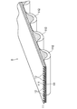
- FIGS. 1A and 1B show a toothed belt B according to an embodiment.
- the toothed belt B according to the embodiment is a meshing transmission belt, and is suitably used for high load transmission applications such as machine tools, printing machines, textile machines, and injection molding machines.
- the belt length of the toothed belt B according to the embodiment is, for example, 500 mm or more and 3000 mm or less.
- the belt width is, for example, 10 mm or more and 200 mm or less.
- the belt thickness (maximum) is, for example, 3 mm or more and 20 mm or less.
- the toothed belt B includes an endless toothed belt main body 11 made of an elastomer made of a polyurethane resin.
- the toothed belt main body 11 has a flat band portion 111 having a horizontally long rectangular cross section, and a plurality of tooth portions 112 integrally provided on the inner peripheral side thereof.
- the plurality of tooth portions 112 are provided at regular intervals in the belt length direction.
- Examples of the tooth profile in the side view of the tooth portion 112 include an STS tooth profile having both sides bulging outward in an arc shape, a trapezoidal tooth profile, and the like.
- the number of teeth of the tooth portion 112 is, for example, 30 or more and 400 or less.
- the tooth width (maximum dimension in the belt length direction) is, for example, 2 mm or more and 10 mm or less.
- the tooth height is, for example, 2 mm or more and 8 mm or less.
- the arrangement pitch is, for example, 8 mm or more and 14 mm or less.
- the polyurethane resin forming the toothed belt main body 11 is a urethane composition in which a compounding agent such as a curing agent and a plasticizer is mixed with a urethane prepolymer and cured by heating and pressurizing.
- Urethane prepolymer is a relatively low molecular weight urethane compound having a plurality of NCO groups at the terminals obtained by the reaction between the isocyanate component and the polyol component.
- the isocyanate component include tolylene diisocyanate (TDI) and diphenylmethane diisocyanate (MDI).
- the polyol component include polytetramethylene ether glycol (PTMG) and the like.
- the urethane prepolymer may be composed of a single urethane compound or a mixture of a plurality of urethane compounds.
- the curing agent examples include 1,4-phenylenediamine, 2,6-diaminotoluene, 1,5-naphthalenediamine, 4,4'-diaminodiphenylmethane, and 3,3'-dichloro-4,4'-diaminodiphenylmethane.
- examples thereof include amine compounds such as (MOCA).
- the curing agent preferably contains one or more of these.
- the curing agent of the amine compound has an ⁇ value (NH 2 groups / NCO groups) of 0.70 or more and 1.10, which is the ratio of the number of moles of NH 2 groups in the curing agent to the number of moles of NCO groups in the urethane prepolymer. It is preferable that they are formulated as follows.
- plasticizer examples include dialkyl phthalates such as dibutyl phthalate (DBP) and dioctyl phthalate (DOP); dialkyl adipates such as dioctyl adipate (DOA); and dialkyl sebacates such as dioctyl sebacate (DOS).
- the plasticizer preferably contains one or more of these.
- the blending amount of the plasticizer is, for example, 3 parts by mass or more and 20 parts by mass or less with respect to 100 parts by mass of the urethane prepolymer.
- Examples of other compounding agents include colorants, antifoaming agents, stabilizers and the like.
- the hardness of the polyurethane resin forming the toothed belt body 11 is, for example, 70 ° or more and 100 ° or less.
- the hardness of this polyurethane resin is measured based on JIS K7312: 1996.
- the toothed belt B includes a carbon fiber core wire 12 embedded in the flat band portion 111 of the toothed belt main body 11.
- the outer diameter of the core wire 12 is preferably 0.6 mm or more and 2.2 mm or less, and more preferably 0.8 mm or more and 1.2 mm or less, from the viewpoint of obtaining excellent durability in high load transmission.
- the carbon fiber constituting the core wire 12 is preferably a PAN-based carbon fiber from the viewpoint of obtaining excellent durability in high load transmission.
- the filament diameter of the carbon fiber is preferably 4 ⁇ m or more and 9 ⁇ m or less, and more preferably 6 ⁇ m or more and 8 ⁇ m or less.
- the total number of carbon fibers constituting the core 12 is preferably 6000 (6K) or more and 48000 (48K) or less, more preferably 9000 (9K), from the viewpoint of obtaining excellent durability in high load transmission. ) Or more 18,000 (18K), more preferably 12,000 (12K). From the same viewpoint, the fineness of the carbon fibers constituting the core wire 12 is preferably 400 tex or more and 3200 tex or less, more preferably 600 tex or more and 1200 tex or less, and further preferably 800 tex or less.
- the core wire 12 is preferably a twisted yarn from the viewpoint of obtaining excellent durability in high load transmission.
- the twisted yarn constituting the core wire 12 include a single twisted yarn, various twisted yarns, and a rung twisted yarn.
- the core wire 12 of the twisted yarn is preferably a single twisted yarn in which a bundle of carbon fiber filaments is twisted in one direction.
- the number of twists of the core wire 12 of the single-twisted yarn is preferably 4 times / 10 cm or more and 12 times / 10 cm or less, and more preferably 6 times / 10 cm or more and 10 times / 10 cm or less.
- an S-twisted yarn, a Z-twisted yarn, or both of them may be used.
- the core wire 12 is provided so as to form a spiral having a pitch in the belt width direction.
- the core wire 12 is composed of two S-twisted yarns and a Z-twisted yarn, and may be provided so as to form a double helix.
- the core wires 12 are arranged so as to extend in parallel at intervals in the belt width direction. At this time, the number of core wires 12 per belt width of 10 mm is excellent in durability in high load transmission. From the viewpoint of obtaining the above, it is preferably 6 pieces / 10 mm or more and 10 pieces / 10 mm or less, and more preferably 7 pieces / 10 mm or more and 9 pieces / 10 mm or less.
- the core wire 12 is subjected to an adhesive treatment such as being immersed in a liquid adhesive in advance and then dried before molding.
- the toothed belt B includes a non-woven fabric 13 embedded along the belt length direction on the inner peripheral side of the embedding position of the core wire 12 in the belt thickness direction in the toothed belt main body 11.
- the nonwoven fabric 13 may be composed of one sheet or a plurality of sheets.
- the nonwoven fabric 13 contains a polyurethane resin that forms the toothed belt main body 11 and is provided so as to form a layer in a side view.
- the portion of the non-woven fabric 13 corresponding to the tooth portion 112 enters the tooth portion 112 so as to bulge toward the inner peripheral side in the side view, and spreads thickly in the belt thickness direction.
- the portion of the nonwoven fabric 13 corresponding between the tooth portions 112 is in contact with the core wire 12 and is thinly compressed in the belt thickness direction.
- Examples of the fiber material constituting the nonwoven fabric 13 include nylon fiber, polyester fiber, aramid fiber, polyketone fiber, carbon fiber and the like.
- the nonwoven fabric 13 may be formed of a single type of fiber or may be formed of a plurality of types of fibers.
- the nonwoven fabric 13 is subjected to an adhesive treatment such as being immersed in a liquid adhesive in advance and then dried before molding.
- the toothed belt B has a belt tension T 0.2 of 70 N / mm or more per 1 mm of belt width when the belt extension rate is 0.2%.
- the belt tension T 0.2 is preferably 80 N / mm or more, more preferably 90 N / mm or more, from the viewpoint of obtaining excellent durability in high load transmission.
- the belt tension T 0.2 is preferably 140 N / mm or less, more preferably 120 N / mm or less, from the viewpoint of avoiding high bending rigidity and impairing bending fatigue resistance.
- the belt tension T 0.5 per 1 mm of the belt width when the belt extension rate is 0.5% is 220 N / mm or more.
- the belt tension T 0.5 is preferably 230 N / mm or more, more preferably 240 N / mm or more, from the viewpoint of obtaining excellent durability in high load transmission.
- the belt tension T 0.5 is preferably 440 N / mm or less, more preferably 300 N / mm or less, from the viewpoint of avoiding high bending rigidity and impairing bending fatigue resistance.
- the toothed belt B according to the embodiment is attached to a pair of flat pulleys 21 of the belt tensile tester 20 each having a pulley diameter of 95.4 mm, and the back surface of the belt is attached. Wrap it so that it touches.
- one flat pulley 21 is separated from the other flat pulley 21 at a speed of 50 mm / min. At this time, the relationship between the displacement between the pair of flat pulleys 21 and the tension detected via any of the pair of flat pulleys 21 is recorded.
- the displacement between the pair of flat pulleys 21 is doubled to calculate the belt elongation amount, which is divided by the belt length of the toothed belt B according to the embodiment in the no-load state, whereby the pair The displacement between the flat pulleys 21 is converted into the belt extension rate. Further, by dividing the detected tension by 2 to calculate the belt tension and dividing it by the belt width of the toothed belt B according to the embodiment, the detected tension is divided into the belt tension per 1 mm of the belt width. Convert.
- the ratio of the belt tension T 0.2 to the belt tension T 0.5 is 0.33 or more.
- the belt tension T 0.2 / belt tension T 0.5 is preferably 0.35 or more, more preferably 0.38 or more, from the viewpoint of obtaining excellent durability in high load transmission. From a practical point of view, the belt tension T 0.2 / belt tension T 0.5 is preferably 0.55 or less, more preferably 0.50 or less, still more preferably 0.45 or less.
- the belt tension T 0.2 is 70 N / mm or more
- the belt tension T 0.5 is 220 N / mm or more
- the ratio of the belt tension T of 0.2 to 0.5 is 0.33 or more, excellent durability in high load transmission can be obtained. This is because the belt tension T 0.2 is 70 N / mm or more and the belt tension T 0.5 is 220 N / mm or more, so that excellent dimensional stability can be obtained in use under a wide range of high loads.
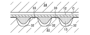
- the non-woven fabric 13 is put on the cylindrical inner mold 31, and the core wire 12 is spirally wound from above.
- concave grooves 32 having a cross section extending in the axial direction corresponding to the tooth portion 112 are provided at a constant pitch at intervals in the circumferential direction, and each concave groove 32 is provided. Since the ridges 33 extending in the axial direction are configured between them, the nonwoven fabric 13 and the core wire 12 are provided so as to be supported by the ridges 33.
- the inner mold 31 is housed in the cylindrical outer mold 34.
- a cavity C for forming a toothed belt body is formed between the inner mold 31 and the outer mold 34.
- a liquid urethane composition in which a compounding agent is mixed with a urethane prepolymer is injected into the closed cavity C, filled, and heated.
- the urethane composition flows and hardens to form the toothed belt body 11 made of polyurethane resin.
- the tooth portion 112 is formed in the concave groove 32.
- the core wire 12 is adhered to and embedded in the toothed belt main body 11.
- the nonwoven fabric 13 is impregnated with the urethane composition and cured, and is adhered to and embedded in the toothed belt main body 11.
- the toothed belt main body 11, the core wire 12, and the non-woven fabric 13 are integrated to form a cylindrical belt slab S.
- the belt slab S is removed from the inner mold 31 and the outer mold 34 and sliced into round slices to obtain the toothed belt B according to the embodiment.
- the toothed belt B composed of the toothed belt main body 11, the core wire 12, and the non-woven fabric 13 is used, but the present invention is not particularly limited to this, and the inner peripheral side of the toothed belt main body is not particularly limited.
- a reinforcing cloth may be provided on the toothed surface and / or the back surface of the toothed belt body on the outer peripheral side.
- the toothed belt body is the toothed belt B formed of polyurethane resin, but the present invention is not particularly limited, and the belt body may be formed of a crosslinked rubber composition.
- the toothed belt B is shown as the transmission belt, but the present invention is not particularly limited to this, and a flat belt, a V-belt, a V-ribbed belt, or the like may be used.
- Example> An example is a toothed belt having an STS tooth profile having the same configuration as that of the above embodiment.
- the toothed belt of the example had a belt length of 800 mm, a belt width of 8 mm, and a belt thickness (maximum) of 4.8 mm.
- the tooth portion was S8M defined by ISO13050: 2014 (E).
- the urethane composition for forming the main body of the toothed belt contains 13 parts by mass of the curing agent 3,3'-dichloro-4,4'-diaminodiphenylmethane and the plasticizer dioctyl with respect to 100 parts by mass of the urethane prepolymer. A compound containing 10 parts by mass of phthalate was used. The hardness measured based on JIS K7312 of the polyurethane resin forming the toothed belt body was 92 °.
- a filament bundle of carbon fiber (Tenax-J UTS50 F22, manufactured by Teijin, 12K, 800tex, filament diameter: 7.0 ⁇ m) with 12,000 filaments is twisted 6 times per 10 cm in length.
- a single twisted yarn twisted in one direction at 10 cm was used.
- S-twisted yarn and Z-twisted yarn were prepared, and they were subjected to an adhesive treatment to be dipped in an adhesive and then dried.
- the core wires of the single twisted yarns of the S twisted yarn and the Z twisted yarn were provided so as to form a double helix by arranging them alternately in the belt width direction.
- the number of core wires per 10 mm belt width was set to eight.
- the outer diameter of the core wire was 0.9 mm.
- non-woven fabric one made of nylon fiber manufactured by the needle punch method without pressurization was used.
- the non-woven fabric was not subjected to an adhesive treatment.
- the belt tension T 0.2 of the toothed belt of the example was 100 N / mm, and the belt tension T 0.5 was 250 N / mm. Therefore, the belt tension T 0.2 / belt tension T 0.5 is 0.40.
- Comparative Example 1 was a toothed belt having the same configuration as that of the example except that the number of core wires per 10 mm belt width was six.
- the belt tension T 0.2 of the toothed belt of Comparative Example 1 was 65 N / mm, and the belt tension T 0.5 was 200 N / mm. Therefore, the belt tension T 0.2 / belt tension T 0.5 is 0.33.
- Comparative Example 2 was a toothed belt having the same configuration as that of the example except that the number of twists per 10 cm of the core wire was 12 times / 10 cm and the number of twists per 10 mm of the core wire was 10. ..
- the outer diameter of the core wire was 1.0 mm.
- the belt tension T 0.2 of the toothed belt of Comparative Example 2 was 80 N / mm, and the belt tension T 0.5 was 260 N / mm. Therefore, the belt tension T 0.2 / belt tension T 0.5 is 0.31.
- Comparative Example 3 was a toothed belt having the same configuration as that of the example except that the number of twists per 10 cm of the core wire was 9 times / 10 cm.
- the outer diameter of the core wire was 1.0 mm.
- the belt tension T 0.2 of the toothed belt of Comparative Example 3 was 80 N / mm, and the belt tension T 0.5 was 210 N / mm. Therefore, the belt tension T 0.2 / belt tension T 0.5 is 0.38.
- FIG. 4 shows the pulley layout of the belt running tester 40 used in the high load durability test.
- the belt running tester 40 has a drive pulley 41 having 22 teeth and a driven pulley 42 having 33 teeth provided on the right side thereof.
- the driven pulley 42 is movably provided on the left and right sides and is configured to be able to load an axial load, and is also configured to be able to load a load torque.
- Each of the toothed belts B of Examples 1 to 3 is wound between the drive pulley 41 and the driven pulley 42 in an atmosphere of 60 ° C., and a fixed shaft load (SW) of 608N is applied to the driven pulley 42.
- a load was applied to apply tension to the toothed belt B, and a load torque of 34.24 Nm was applied, and in that state, the drive pulley 41 was rotated at a rotation speed of 4212 rpm. Then, the time until the toothed belt B was cut was measured, and the time was taken as the high load endurance life.
- Table 1 shows the test results. According to this, it can be seen that the examples are much more durable in high load transmission than the comparative examples 1 to 3.
- the present invention is useful in the technical field of transmission belts.
- Toothed belt (transmission belt) C Cavity S Belt slab 11 Toothed belt body 111 Flat belt 112 Tooth 12 Core wire 13 Non-woven fabric 20 Belt tensile tester 21 Flat pulley 31 Inner mold 32 Concave groove 33 Protrusion 34 Outer mold 40 Belt running tester 41 Drive pulley 42 Driven pulley
Landscapes
- Engineering & Computer Science (AREA)
- General Engineering & Computer Science (AREA)
- Mechanical Engineering (AREA)
- Textile Engineering (AREA)
- Yarns And Mechanical Finishing Of Yarns Or Ropes (AREA)
- Compositions Of Macromolecular Compounds (AREA)
Priority Applications (5)
| Application Number | Priority Date | Filing Date | Title |
|---|---|---|---|
| CN202180031931.6A CN115461558B (zh) | 2020-07-03 | 2021-07-01 | 传动带 |
| EP21831812.9A EP4141286B1 (en) | 2020-07-03 | 2021-07-01 | Transmission belt |
| JP2022506968A JP7043690B1 (ja) | 2020-07-03 | 2021-07-01 | 伝動ベルト |
| JP2022039836A JP7689095B2 (ja) | 2020-07-03 | 2022-03-15 | 伝動ベルト |
| US17/994,270 US11644082B2 (en) | 2020-07-03 | 2022-11-25 | Transmission belt |
Applications Claiming Priority (2)
| Application Number | Priority Date | Filing Date | Title |
|---|---|---|---|
| JP2020-115523 | 2020-07-03 | ||
| JP2020115523 | 2020-07-03 |
Related Child Applications (1)
| Application Number | Title | Priority Date | Filing Date |
|---|---|---|---|
| US17/994,270 Continuation US11644082B2 (en) | 2020-07-03 | 2022-11-25 | Transmission belt |
Publications (1)
| Publication Number | Publication Date |
|---|---|
| WO2022004835A1 true WO2022004835A1 (ja) | 2022-01-06 |
Family
ID=79316353
Family Applications (1)
| Application Number | Title | Priority Date | Filing Date |
|---|---|---|---|
| PCT/JP2021/024894 Ceased WO2022004835A1 (ja) | 2020-07-03 | 2021-07-01 | 伝動ベルト |
Country Status (5)
| Country | Link |
|---|---|
| US (1) | US11644082B2 (https=) |
| EP (1) | EP4141286B1 (https=) |
| JP (2) | JP7043690B1 (https=) |
| CN (1) | CN115461558B (https=) |
| WO (1) | WO2022004835A1 (https=) |
Families Citing this family (1)
| Publication number | Priority date | Publication date | Assignee | Title |
|---|---|---|---|---|
| JP7085699B1 (ja) * | 2021-01-25 | 2022-06-16 | 三ツ星ベルト株式会社 | 歯付ベルト |
Citations (4)
| Publication number | Priority date | Publication date | Assignee | Title |
|---|---|---|---|---|
| JP2001090789A (ja) * | 1999-09-21 | 2001-04-03 | Bando Chem Ind Ltd | Vリブドベルト |
| JP2004347111A (ja) * | 2003-04-28 | 2004-12-09 | Hokushin Ind Inc | 歯付き駆動ベルト |
| JP2005024075A (ja) | 2003-07-03 | 2005-01-27 | Mitsuboshi Belting Ltd | 歯付ベルト |
| JP2011133029A (ja) * | 2009-12-24 | 2011-07-07 | Nitta Corp | 平ベルト |
Family Cites Families (34)
| Publication number | Priority date | Publication date | Assignee | Title |
|---|---|---|---|---|
| AT268791B (de) * | 1965-05-29 | 1969-02-25 | Continental Gummi Werke Ag | Antriebsriemen |
| JPH0642120Y2 (ja) * | 1986-06-19 | 1994-11-02 | 芦森工業株式会社 | タイミングベルト |
| US5268221A (en) * | 1990-02-23 | 1993-12-07 | Bando Chemical Industries, Ltd. | Fiber reinforced rubber articles |
| JP3007371B2 (ja) * | 1990-02-23 | 2000-02-07 | バンドー化学株式会社 | 繊維補強ゴム製品 |
| JPH0425643A (ja) * | 1990-05-15 | 1992-01-29 | Bando Chem Ind Ltd | 繊維補強ゴム製品 |
| JP2545208Y2 (ja) * | 1992-10-13 | 1997-08-25 | 株式会社椿本チエイン | 歯付ベルト |
| US5529545A (en) * | 1993-02-23 | 1996-06-25 | Unitta Co., Ltd. | Toothed belt |
| JPH07208558A (ja) * | 1994-01-13 | 1995-08-11 | Bando Chem Ind Ltd | 歯付ベルト |
| JP2869025B2 (ja) * | 1995-07-24 | 1999-03-10 | バンドー化学株式会社 | ベルト用抗張体及びベルト |
| US5807194A (en) * | 1996-10-31 | 1998-09-15 | The Gates Corporation | Toothed belt |
| JP3441987B2 (ja) * | 1998-12-04 | 2003-09-02 | ゲイツ・ユニッタ・アジア株式会社 | 歯付きベルト |
| GB2349113B (en) * | 1999-04-21 | 2003-07-02 | Gates Corp | Wear resistant belts and a process for their manufacture |
| DE60108440T2 (de) * | 2000-04-28 | 2006-02-16 | Mitsuboshi Belting Ltd., Kobe | Treibriemen und Herstellungsverfahren eines Treibriemens. |
| CA2419277C (en) * | 2000-08-18 | 2007-07-10 | The Gates Corporation | Power transmission belt having high modulus adhesive rubber member |
| EP1384013B1 (en) * | 2001-04-12 | 2007-08-15 | The Gates Corporation | Thermoplastic jacket belt |
| JP3964725B2 (ja) * | 2002-01-21 | 2007-08-22 | 本田技研工業株式会社 | 歯付きベルト伝動装置 |
| CA2556750C (en) * | 2004-02-23 | 2014-04-15 | Carlo Baldovino | Toothed belt |
| JP2006097787A (ja) * | 2004-09-29 | 2006-04-13 | Tsubakimoto Chain Co | 歯付ベルト |
| JPWO2007110974A1 (ja) * | 2006-03-24 | 2009-08-06 | バンドー化学株式会社 | 伝動ベルト |
| US8142316B2 (en) * | 2006-12-05 | 2012-03-27 | Veyance Technologies, Inc. | Power transmission belts |
| CN101688586A (zh) * | 2007-07-03 | 2010-03-31 | 盖茨公司 | 动力传输带 |
| JP5204611B2 (ja) * | 2008-10-15 | 2013-06-05 | バンドー化学株式会社 | 歯付ベルト |
| JP5343295B2 (ja) * | 2009-06-23 | 2013-11-13 | チェジアン キングランド トランスミッション インダストリー カンパニー リミテッド | 摩擦伝動および噛合伝動を組み合わせたvベルト伝動システム |
| JP5002043B2 (ja) * | 2009-11-13 | 2012-08-15 | 三ツ星ベルト株式会社 | ゴム製歯付ベルトおよび歯付ベルト用ゴム組成物 |
| JP5465346B1 (ja) * | 2013-01-22 | 2014-04-09 | 株式会社椿本チエイン | 歯付ベルト |
| DE102013104757A1 (de) * | 2013-05-08 | 2014-11-13 | Contitech Antriebssysteme Gmbh | Verfahren zur Fertigung eines Riemens mit präparierten Zugträgern mit Hüllschicht |
| WO2014185030A1 (ja) * | 2013-05-15 | 2014-11-20 | バンドー化学株式会社 | 歯付ベルト及びその製造方法、ベルト伝動装置 |
| JP6530276B2 (ja) * | 2015-08-20 | 2019-06-12 | 三ツ星ベルト株式会社 | ベルトシステムおよびその歯付きベルト |
| US10220545B2 (en) * | 2016-04-30 | 2019-03-05 | Contitech Antriebssysteme Gmbh | Water based urethane as predip for carbon fiber cord |
| JP6640921B2 (ja) * | 2017-06-20 | 2020-02-05 | 三ツ星ベルト株式会社 | Vリブドベルト及びその製造方法 |
| CN110869640B (zh) * | 2017-07-11 | 2022-04-08 | 三之星机带株式会社 | 斜齿带及带传动装置 |
| EP3768734B1 (en) * | 2018-03-19 | 2025-10-22 | ExxonMobil Chemical Patents Inc. | Elastomeric propylene-alpha-olefin-diene terpolymer compositions |
| US20210040682A1 (en) * | 2018-03-19 | 2021-02-11 | Nippon Sheet Glass Company, Limited | Rubber-reinforcing cord, method for producing the same, and rubber product |
| JP6641513B2 (ja) * | 2018-04-06 | 2020-02-05 | 三ツ星ベルト株式会社 | はす歯ベルトおよびベルト伝動装置 |
-
2021
- 2021-07-01 EP EP21831812.9A patent/EP4141286B1/en active Active
- 2021-07-01 WO PCT/JP2021/024894 patent/WO2022004835A1/ja not_active Ceased
- 2021-07-01 JP JP2022506968A patent/JP7043690B1/ja active Active
- 2021-07-01 CN CN202180031931.6A patent/CN115461558B/zh active Active
-
2022
- 2022-03-15 JP JP2022039836A patent/JP7689095B2/ja active Active
- 2022-11-25 US US17/994,270 patent/US11644082B2/en active Active
Patent Citations (4)
| Publication number | Priority date | Publication date | Assignee | Title |
|---|---|---|---|---|
| JP2001090789A (ja) * | 1999-09-21 | 2001-04-03 | Bando Chem Ind Ltd | Vリブドベルト |
| JP2004347111A (ja) * | 2003-04-28 | 2004-12-09 | Hokushin Ind Inc | 歯付き駆動ベルト |
| JP2005024075A (ja) | 2003-07-03 | 2005-01-27 | Mitsuboshi Belting Ltd | 歯付ベルト |
| JP2011133029A (ja) * | 2009-12-24 | 2011-07-07 | Nitta Corp | 平ベルト |
Non-Patent Citations (1)
| Title |
|---|
| See also references of EP4141286A4 |
Also Published As
| Publication number | Publication date |
|---|---|
| JP2022091819A (ja) | 2022-06-21 |
| JP7043690B1 (ja) | 2022-03-29 |
| CN115461558B (zh) | 2023-03-28 |
| EP4141286A1 (en) | 2023-03-01 |
| US20230088538A1 (en) | 2023-03-23 |
| EP4141286A4 (en) | 2023-10-25 |
| JPWO2022004835A1 (https=) | 2022-01-06 |
| EP4141286B1 (en) | 2024-10-09 |
| JP7689095B2 (ja) | 2025-06-05 |
| CN115461558A (zh) | 2022-12-09 |
| US11644082B2 (en) | 2023-05-09 |
Similar Documents
| Publication | Publication Date | Title |
|---|---|---|
| JP7233461B2 (ja) | 歯付ベルト | |
| JP5204611B2 (ja) | 歯付ベルト | |
| JP7406051B1 (ja) | 歯付ベルト | |
| JP2025172975A (ja) | 伝動ベルト | |
| JP7043690B1 (ja) | 伝動ベルト | |
| JP2022013158A (ja) | 歯付ベルト | |
| US11719309B2 (en) | Toothed belt | |
| JP7839373B1 (ja) | 伝動ベルト | |
| WO2024024435A1 (ja) | 歯付ベルト | |
| WO2026034098A1 (ja) | 歯付ベルト及び伝動システム | |
| WO2024219230A1 (ja) | 伝動ベルト及びその製造方法並びに心線 | |
| JP2000009185A (ja) | 歯付ベルト |
Legal Events
| Date | Code | Title | Description |
|---|---|---|---|
| ENP | Entry into the national phase |
Ref document number: 2022506968 Country of ref document: JP Kind code of ref document: A |
|
| 121 | Ep: the epo has been informed by wipo that ep was designated in this application |
Ref document number: 21831812 Country of ref document: EP Kind code of ref document: A1 |
|
| ENP | Entry into the national phase |
Ref document number: 2021831812 Country of ref document: EP Effective date: 20221122 |
|
| NENP | Non-entry into the national phase |
Ref country code: DE |