WO2022004304A1 - ブレーズド回折光学素子、及びブレーズド回折光学素子の製造方法 - Google Patents
ブレーズド回折光学素子、及びブレーズド回折光学素子の製造方法 Download PDFInfo
- Publication number
- WO2022004304A1 WO2022004304A1 PCT/JP2021/021755 JP2021021755W WO2022004304A1 WO 2022004304 A1 WO2022004304 A1 WO 2022004304A1 JP 2021021755 W JP2021021755 W JP 2021021755W WO 2022004304 A1 WO2022004304 A1 WO 2022004304A1
- Authority
- WO
- WIPO (PCT)
- Prior art keywords
- blazed
- intermediate layer
- steep slope
- optical element
- slope
- Prior art date
Links
Images


Classifications
-
- G—PHYSICS
- G02—OPTICS
- G02B—OPTICAL ELEMENTS, SYSTEMS OR APPARATUS
- G02B5/00—Optical elements other than lenses
- G02B5/18—Diffraction gratings
- G02B5/1847—Manufacturing methods
- G02B5/1857—Manufacturing methods using exposure or etching means, e.g. holography, photolithography, exposure to electron or ion beams
-
- G—PHYSICS
- G02—OPTICS
- G02B—OPTICAL ELEMENTS, SYSTEMS OR APPARATUS
- G02B3/00—Simple or compound lenses
- G02B3/02—Simple or compound lenses with non-spherical faces
- G02B3/08—Simple or compound lenses with non-spherical faces with discontinuous faces, e.g. Fresnel lens
-
- B—PERFORMING OPERATIONS; TRANSPORTING
- B29—WORKING OF PLASTICS; WORKING OF SUBSTANCES IN A PLASTIC STATE IN GENERAL
- B29D—PRODUCING PARTICULAR ARTICLES FROM PLASTICS OR FROM SUBSTANCES IN A PLASTIC STATE
- B29D11/00—Producing optical elements, e.g. lenses or prisms
- B29D11/00009—Production of simple or compound lenses
- B29D11/00269—Fresnel lenses
-
- B—PERFORMING OPERATIONS; TRANSPORTING
- B29—WORKING OF PLASTICS; WORKING OF SUBSTANCES IN A PLASTIC STATE IN GENERAL
- B29D—PRODUCING PARTICULAR ARTICLES FROM PLASTICS OR FROM SUBSTANCES IN A PLASTIC STATE
- B29D11/00—Producing optical elements, e.g. lenses or prisms
- B29D11/00865—Applying coatings; tinting; colouring
- B29D11/00884—Spin coating
-
- B—PERFORMING OPERATIONS; TRANSPORTING
- B29—WORKING OF PLASTICS; WORKING OF SUBSTANCES IN A PLASTIC STATE IN GENERAL
- B29D—PRODUCING PARTICULAR ARTICLES FROM PLASTICS OR FROM SUBSTANCES IN A PLASTIC STATE
- B29D11/00—Producing optical elements, e.g. lenses or prisms
- B29D11/02—Artificial eyes from organic plastic material
- B29D11/023—Implants for natural eyes
-
- G—PHYSICS
- G02—OPTICS
- G02C—SPECTACLES; SUNGLASSES OR GOGGLES INSOFAR AS THEY HAVE THE SAME FEATURES AS SPECTACLES; CONTACT LENSES
- G02C7/00—Optical parts
- G02C7/02—Lenses; Lens systems ; Methods of designing lenses
- G02C7/06—Lenses; Lens systems ; Methods of designing lenses bifocal; multifocal ; progressive
-
- A—HUMAN NECESSITIES
- A61—MEDICAL OR VETERINARY SCIENCE; HYGIENE
- A61F—FILTERS IMPLANTABLE INTO BLOOD VESSELS; PROSTHESES; DEVICES PROVIDING PATENCY TO, OR PREVENTING COLLAPSING OF, TUBULAR STRUCTURES OF THE BODY, e.g. STENTS; ORTHOPAEDIC, NURSING OR CONTRACEPTIVE DEVICES; FOMENTATION; TREATMENT OR PROTECTION OF EYES OR EARS; BANDAGES, DRESSINGS OR ABSORBENT PADS; FIRST-AID KITS
- A61F2/00—Filters implantable into blood vessels; Prostheses, i.e. artificial substitutes or replacements for parts of the body; Appliances for connecting them with the body; Devices providing patency to, or preventing collapsing of, tubular structures of the body, e.g. stents
- A61F2/02—Prostheses implantable into the body
- A61F2/14—Eye parts, e.g. lenses, corneal implants; Implanting instruments specially adapted therefor; Artificial eyes
- A61F2/16—Intraocular lenses
- A61F2/1613—Intraocular lenses having special lens configurations, e.g. multipart lenses; having particular optical properties, e.g. pseudo-accommodative lenses, lenses having aberration corrections, diffractive lenses, lenses for variably absorbing electromagnetic radiation, lenses having variable focus
- A61F2/1654—Diffractive lenses
-
- A—HUMAN NECESSITIES
- A61—MEDICAL OR VETERINARY SCIENCE; HYGIENE
- A61F—FILTERS IMPLANTABLE INTO BLOOD VESSELS; PROSTHESES; DEVICES PROVIDING PATENCY TO, OR PREVENTING COLLAPSING OF, TUBULAR STRUCTURES OF THE BODY, e.g. STENTS; ORTHOPAEDIC, NURSING OR CONTRACEPTIVE DEVICES; FOMENTATION; TREATMENT OR PROTECTION OF EYES OR EARS; BANDAGES, DRESSINGS OR ABSORBENT PADS; FIRST-AID KITS
- A61F2250/00—Special features of prostheses classified in groups A61F2/00 - A61F2/26 or A61F2/82 or A61F9/00 or A61F11/00 or subgroups thereof
- A61F2250/0014—Special features of prostheses classified in groups A61F2/00 - A61F2/26 or A61F2/82 or A61F9/00 or A61F11/00 or subgroups thereof having different values of a given property or geometrical feature, e.g. mechanical property or material property, at different locations within the same prosthesis
- A61F2250/0026—Special features of prostheses classified in groups A61F2/00 - A61F2/26 or A61F2/82 or A61F9/00 or A61F11/00 or subgroups thereof having different values of a given property or geometrical feature, e.g. mechanical property or material property, at different locations within the same prosthesis differing in surface structures
-
- G—PHYSICS
- G02—OPTICS
- G02B—OPTICAL ELEMENTS, SYSTEMS OR APPARATUS
- G02B5/00—Optical elements other than lenses
- G02B5/18—Diffraction gratings
- G02B5/1814—Diffraction gratings structurally combined with one or more further optical elements, e.g. lenses, mirrors, prisms or other diffraction gratings
-
- G—PHYSICS
- G02—OPTICS
- G02B—OPTICAL ELEMENTS, SYSTEMS OR APPARATUS
- G02B5/00—Optical elements other than lenses
- G02B5/18—Diffraction gratings
- G02B5/1876—Diffractive Fresnel lenses; Zone plates; Kinoforms
Definitions
- the technique of the present disclosure relates to a blazed diffractive optical element and a method for manufacturing a blazed diffractive optical element.
- Japanese Unexamined Patent Publication No. 2011-107586 discloses a diffractive optical element in which a plurality of diffraction gratings made of at least three types of materials are laminated.
- a plurality of diffraction gratings are made of materials M1A and M1B different from each other, and the lattice side edges of the grating portion are contacted or arranged close to each other in the lattice pitch direction.
- a first combination portion made of, and a second combination part made of two diffraction gratings made of materials M2A and M2B different from each other, in which at least one material is different from the material of the two diffraction gratings of the first combination part.
- the values of the refractive indexes N2Ad and N2Bd, and the Abbe numbers ⁇ 2A and ⁇ 2B are appropriately set.
- One embodiment according to the technique of the present disclosure is a blazed diffraction grating capable of suppressing ghosts caused by incident light as compared with the case where the first blazed member and the second blazed member are directly laminated.
- a method for manufacturing an element and a blazed diffraction optical element is provided.
- a first aspect according to the technique of the present disclosure is a blazed grating, which has a first blazed member and a second blazed member, and the first blazed member and the second blazed member function as a blazed diffraction grating.
- a lattice pair and an intermediate layer located between the first blazed member and the second blazed member are provided, the refractive index of the first blazed member is Na, the refractive index of the intermediate layer is N, and the second blazed member.
- This is a blazed grating optical element in which the magnitude relationship of Na> N> Nb is established when the refractive index of is Nb.
- the thickness of the intermediate layer is t
- ⁇ c is a critical angle, h ⁇ t.
- the first blazed member has a first sawtooth surface
- the second blazed member has a second sawtooth surface
- the first sawtooth surface and the second are complementary to the first aspect or the second aspect, in which the serrated surface is complementarily engaged with the intermediate layer.
- the first blazed member has a first sawtooth surface
- the second blazed member has a second sawtooth surface
- the first sawtooth surface has a first sawtooth surface.
- the 1st steep slope and the 1st gentle slope having a gentler slope than the 1st steep slope are formed
- the 2nd serrated surface is formed by the 2nd steep slope and the 2nd gentle slope having a gentler slope than the 2nd steep slope.
- a fifth aspect of the technique of the present disclosure is that the first serrated surface is formed by a first steep slope and a first gentle slope having a gentler slope than the first steep slope, and the second serrated surface is a second. It is composed of two steep slopes and a second gentle slope with a gentler slope than the second steep slope, and an intermediate layer is formed between the first serrated surface and the second serrated surface with the first steep slope and the second steep slope.
- the blazed diffraction optical element according to the third aspect is arranged between the two.
- a sixth aspect according to the technique of the present disclosure is that the first blazed member has a first serrated surface, the second blazed member has a second serrated surface, and the first serrated surface has a first sawtooth surface.
- the 1 steep slope and the 1st gentle slope having a gentler slope than the 1st steep slope are formed, and the 2nd serrated surface is formed by the 2nd steep slope and the 2nd gentle slope having a gentler slope than the 2nd steep slope.
- the thickness of the intermediate layer between the first serrated surface and the second serrated surface between the first steep slope and the second steep slope is t, and the lattice heights of the first blazed member and the second blazed member are defined as t.
- This is a blazed diffraction grating according to the first aspect in which the inequality of h ⁇ t ⁇ tan ⁇ c and the equation of ⁇ c asin (Nb / Na) are established when h is defined as h and ⁇ c is defined as a critical angle.
- a seventh aspect according to the technique of the present disclosure is that the first blazed member has a first reference plane, the second blazed member has a second reference plane, and the first steep slope and the first gentle slope have a first reference plane.
- the surface rising from the first reference plane, the second steep slope and the second gentle slope are the planes rising from the second reference plane, the first steep slope is perpendicular to the first reference plane, and the second The blazed diffraction grating according to any one of the fourth to sixth aspects, wherein the steep slope is perpendicular to the second reference plane.
- An eighth aspect according to the technique of the present disclosure is any one of the third to seventh aspects in which the first sawtooth surface and the second sawtooth surface are engaged with each other by the thickness of the intermediate layer. It is a blazed diffraction optical element which concerns on one aspect.
- a ninth aspect according to the technique of the present disclosure is any of the first to eighth aspects, wherein the intermediate layer is composed of a plurality of layers having a refractive index that becomes smaller from the first blazed member side to the second blazed member side. It is a blazed diffraction grating according to one aspect.
- a tenth aspect according to the technique of the present disclosure is a blazed diffraction optical element according to any one of the first to ninth aspects in which the intermediate layer is formed in a film shape.
- the eleventh aspect according to the technique of the present disclosure is the blazed diffraction according to any one of the first to tenth aspects in which the blaze angle of the first blaze member and the blaze angle of the second blaze member are the same. It is an optical element.
- a twelfth aspect according to the technique of the present disclosure is a blazed according to any one of the first to eleventh aspects in which the lattice height of the first blazed member and the lattice height of the second blazed member are the same. It is a diffraction optical element.
- a thirteenth aspect according to the technique of the present disclosure is a blazed diffraction grating, comprising a blazed member and a layer provided on the blazed member, and the refractive index of the layer is the refractive index of the blazed member.
- a fourteenth aspect according to the technique of the present disclosure is that the surrounding environment is anterior chamber water in the eye, and the refractive index of the layer is between the refractive index of the blazed member and the refractive index of the anterior chamber water.
- a blazed diffraction grating according to a thirteenth aspect is that the surrounding environment is anterior chamber water in the eye, and the refractive index of the layer is between the refractive index of the blazed member and the refractive index of the anterior chamber water.
- the refractive index of the anterior chamber water is A
- the refractive index of the surface layer is B
- the refractive index of the blazed member is C
- the magnitude relationship of A ⁇ B ⁇ C is established. It is a blazed diffraction optical element which concerns on the 14th aspect which holds.
- a seventeenth aspect according to the technique of the present disclosure is the fifteenth aspect or the fifteenth aspect in which the blazed member has a serrated surface and the layer is formed on the serrated surface in a shape corresponding to the serrated surface.
- the blazed diffraction grating according to the sixteenth aspect is the fifteenth aspect or the fifteenth aspect in which the blazed member has a serrated surface and the layer is formed on the serrated surface in a shape corresponding to the serrated surface.
- the eighteenth aspect according to the technique of the present disclosure is the blazed diffraction optical element according to the seventeenth aspect, wherein the serrated surface is formed of a steep slope and a gentle slope having a gentler slope than the steep slope.
- a nineteenth aspect according to the technique of the present disclosure is that the blazed member has a reference plane, the steep slope and the gentle slope are planes rising from the reference plane, and the steep slope is perpendicular to the reference plane.
- the blazed diffraction grating according to the eighteenth aspect is that the blazed member has a reference plane, the steep slope and the gentle slope are planes rising from the reference plane, and the steep slope is perpendicular to the reference plane.
- a twentieth aspect according to the technique of the present disclosure is a blazed diffraction according to any one of the 17th to 19th aspects in which the serrated surface and the anterior chamber water are in contact with each other with a difference in the thickness of the layer. It is an optical element.
- a twenty-first aspect according to the technique of the present disclosure is any one of the fourteenth to twenty-seventh aspects, wherein the surface layer is composed of a plurality of layers having a refractive index that increases from the anterior chamber water side to the blazed member side.
- the 22nd aspect according to the technique of the present disclosure is a blazed diffraction optical element according to any one of the 13th to 21st aspects in which the surface layer is formed in a film shape.
- a 23rd aspect according to the technique of the present disclosure is a method for manufacturing a blazed grating, which is intermediate between a step of forming a first blazed member and a step of forming an intermediate layer in a blazed portion of the first blazed member.
- a step of forming a second blazed member paired with the first blazed member on the side opposite to the first blazed member side of the layer is provided, the refractive index of the first blazed member is Na, and the refractive index of the intermediate layer is N.
- This is a method for manufacturing a blazed diffraction grating in which the magnitude relationship of Na> N> Nb is established when the refractive index of the second blazed member is Nb.
- the 24th aspect according to the technique of the present disclosure is the method for manufacturing a blazed diffraction optical element according to the 23rd aspect, in which the step of forming the intermediate layer is the step of forming the intermediate layer by using a spin coat.
- the thickness of the intermediate layer is t
- a 26th aspect according to the technique of the present disclosure is a step in which the first blazed member has a first sawtooth surface, the second blazed member has a second sawtooth surface, and the second blazed member is formed.
- the method for manufacturing a blazed diffraction grating according to any one of the 23rd to 25th embodiments wherein the first serrated surface and the second serrated surface are engaged with each other by shifting the thickness of the intermediate layer. be.
- vertical is an error generally allowed in the technical field to which the technology of the present disclosure belongs, in addition to the perfect verticality, which is contrary to the purpose of the technology of the present disclosure. It refers to the vertical in the sense that it includes an error that does not occur.
- orthogonality is an error generally allowed in the technical field to which the technique of the present disclosure belongs, in addition to the perfect orthogonality, which is contrary to the purpose of the technique of the present disclosure. It refers to orthogonality in the sense that it includes an error that does not occur.
- parallel is an error generally allowed in the technical field to which the technology of the present disclosure belongs, in addition to the perfect parallelism, which is contrary to the purpose of the technology of the present disclosure. It refers to parallelism in the sense that it includes an error that does not occur.
- identical is an error generally allowed in the technical field to which the technology of the present disclosure belongs, in addition to being completely the same, which is contrary to the purpose of the technology of the present disclosure. It refers to the same in the sense that it includes an error to the extent that it does not occur.
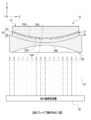
- the junction optical element 10 includes a pair of lenses and a laminated blazed diffraction optical element 12.
- the junction optical element 10 is used, for example, as a lens of an optical device (for example, a digital camera, a projector, a microscope, etc.) and a lens of a vision correction tool (for example, eyeglasses and contact lenses).
- the pair of lenses included in the junction optical element 10 is a glass lens and transmits ultraviolet UV rays (see FIGS. 8, 10 and 13).
- a plano-convex lens 14 see also FIG. 2
- a biconcave lens 16 see also FIG. 3
- a combination of a plano-convex lens 14 and a biconcave lens 16 is illustrated as a pair of lenses, but this is only an example, and the pair of lenses is a combination of other types of lenses (for example, a biconvex lens). It may be a combination with a plano-concave lens).
- the pair of lenses does not have to be made of glass, and may be made of resin.
- the thickness direction of the plano-convex lens 14 and the biconcave lens 16 is the Z direction
- the width direction of the plano-convex lens 14 and the biconcave lens 16 is the X direction
- the depth of the plano-convex lens 14 and the biconcave lens 16 in the figure The direction, that is, the direction orthogonal to the Z direction and the X direction will be described as the Y direction.
- the laminated blazed diffraction optical element 12 is an example of the "blazeed diffraction optical element" according to the technique of the present disclosure, and includes a blazed diffraction grating pair 18.
- the blazed diffraction grating pair 18 has a first blazed member 20 and a second blazed member 22, and functions as a diffraction grating by the first blazed member 20 and the second blazed member 22.
- the first blazed member 20 has a front surface and a back surface in the Z direction, and the back surface is joined to the convex surface 14A of the plano-convex lens 14 (see also FIG. 2).
- the surface of the first blazed member 20 is the first serrated surface 20A.
- the first sawtooth surface 20A is formed in a cross-sectional view sawtooth shape.
- the wedge-shaped grooves 26 are concentrically formed on the first sawtooth surface 20A.
- the second blazed member 22 has a front surface and a back surface in the Z direction, and the back surface is joined to one concave surface 16A (see also FIG. 3) of the biconcave lens 16.
- the surface of the second blazed member 22 is the second serrated surface 22A.
- the second sawtooth surface 22A is formed in a cross-sectional view sawtooth shape.
- the wedge-shaped grooves 28 are concentrically formed on the second serrated surface 22A.
- the laminated blazed diffraction optical element 12 includes an intermediate layer 24.
- the intermediate layer 24 is located between the first blazed member 20 and the second blazed member 22.
- the refractive index of the first blazed member 20 is Na
- the refractive index of the intermediate layer 24 is N
- the refractive index of the second blazed member 22 is Nb
- the magnitude relationship of "Na> N> Nb" is established.
- “1.58” is shown as an example of the refractive index Na
- "1.57” is shown as an example of the refractive index N
- “1.57” is shown as an example of the refractive index Nb.
- “1.56" is shown.
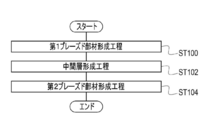
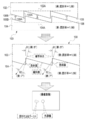
- FIG. 5 shows an example of a method for manufacturing the laminated blazed diffraction optical element 12.
- the manufacturing method shown in FIG. 5 includes a first blazed member forming step of step ST100, an intermediate layer forming step of step ST102, and a second blazed member forming step of step ST104.
- step ST100 the first blazed member 20 is formed.
- step ST102 the intermediate layer 24 is formed on the first serrated surface 20A of the first blazed member 20.
- the first serrated surface 20A is an example of a "blazed portion" according to the technique of the present disclosure.
- step ST104 a second blazed member 22 paired with the first blazed member 20 is formed on the side opposite to the first blazed member 20 side of the intermediate layer 24.
- the first blazed member forming step, the intermediate layer forming step, and the second blazed member forming step will be described in more detail.
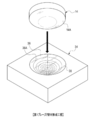
- the cavity 34 is used as an example, as shown in FIG.
- the cavity 34 is a mold for molding the first serrated surface 20A.
- a recess 36 is formed in the central portion of the cavity 34.
- the recess 36 is formed in a bowl shape.
- the surface of the recess 36 is a concentric surface 36A.
- the concentric surface 36A is a surface on which a wedge-shaped groove (for example, a groove corresponding to the wedge-shaped groove shown in FIG. 4) is formed concentrically around the center of the bottom of the recess 36.
- the size and shape of the concentric surface 36A corresponds to the second serrated surface 22A. That is, the concentric surface 36A is formed to have the same size and shape as the second serrated surface 22A.
- the liquid ultraviolet curable resin 38 for the first blazed member 20 is poured into the recess 36 so that air bubbles do not enter.
- the size and shape of the concentric surface 36A take into consideration the shrinkage rate of the ultraviolet curable resin 38 when the ultraviolet UV (see FIG. 8) is irradiated to the ultraviolet curable resin 38 in the recess 36 in a later step. It is designed to be.
- a plano-convex lens 14 is inserted into the recess 36 so that the convex surface 14A covers the recess 36. That is, the plano-convex lens 14 is submerged in the ultraviolet curable resin 38 in the recess 36 from the convex surface 14A in a state where the convex surface 14A faces the concentric surface 36A.
- the ultraviolet curable resin 38 overflowing from the recess 36 is wiped off.
- the ultraviolet irradiation device 40 receives ultraviolet UV rays from the plane 14B (the surface opposite to the convex surface 14A) side of the plano-convex lens 14. Irradiate.
- the ultraviolet UV is transmitted through the plano-convex lens 14 and irradiated to the ultraviolet curable resin 38 in the recess 36.
- the ultraviolet curable resin 38 is cured, and the first blazed member 20 is formed on the convex surface 14A (see FIGS. 1, 4, and 9).
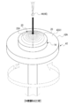
- the plano-convex lens 14 is taken out from the cavity 34. Then, as shown in FIG. 9, the plano-convex lens 14 is installed on the upper surface 42A1 of the disk base 42A of the spin coater 42 with the first sawtooth surface 20A facing upward. The center of the plane 14B (see FIG. 8) of the plano-convex lens 14 is aligned with the center of the top surface 42A1, and the plano-convex lens 14 is attached to the top surface 42A1.
- Examples of the method of attaching the plano-convex lens 14 to the upper surface 42A1 include a method of attaching by suction and / or a method of attaching by a pressing member.
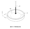
- the liquid ultraviolet curable resin 44 for the intermediate layer 24 is dropped toward the center of the first serrated surface 20A.
- the ultraviolet curable resin 44 is preferably an acrylic or epoxy-based ultraviolet curable resin.
- a thermosetting resin may be applied instead of the ultraviolet curable resin. It is also possible to adjust the refractive index of the intermediate layer 24 by changing the substituent R of the methacrylate-based polymer. Further, the refractive index of the intermediate layer 24 may be adjusted by adjusting the mixing ratio of a plurality of types of materials.
- the disk base 42A is rotated at high speed in a state where the ultraviolet curable resin 44 is dropped toward the center of the first serrated surface 20A. Centrifugal force is applied to the ultraviolet curable resin 44 by the rotation of the disk base 42A, and the ultraviolet curable resin 44 is diffusely coated on the entire first serrated surface 20A.
- the ultraviolet irradiation device 40 irradiates the entire ultraviolet curable resin 44 diffusely coated on the entire first serrated surface 20A with ultraviolet UV.
- the ultraviolet curable resin 44 is cured on the first sawtooth surface 20A, and the intermediate layer 24 is formed into a film on the first sawtooth surface 20A.
- the intermediate layer 24 is a single layer, one film forming step is sufficient, but when the intermediate layer 24 is made into multiple layers, the same film forming step is repeated for the number of layers. ..
- the plano-convex lens 14 is inserted into the concave surface 16A side of both concave lenses 16 so that the intermediate layer 24 covers the concave surface 16A. That is, the plano-convex lens 14 is submerged from the intermediate layer 24 in the ultraviolet curable resin 48 on the concave surface 16A side of both concave lenses 16 in a state where the intermediate layer 24 faces the concave surface 16A. The ultraviolet curable resin 48 overflowing from the concave surface 16A is wiped off.
- the ultraviolet irradiation device 50 reverses the other concave surface 16B (concave surface 16A) of the biconcave lens 16.
- (Side surface) Irradiate ultraviolet UV from the side.
- the ultraviolet UV is transmitted through the biconcave lens 16 and irradiated to the ultraviolet curable resin 48.
- the ultraviolet curable resin 48 is cured, and the second blazed member 22 is formed on the concave surface 16A.
- ⁇ Conventional laminated blazed diffraction optical element> 14 and 15 show, as an example of the conventional diffractive optical element, a laminated blazed diffraction optical element that does not include an intermediate layer, that is, a laminated blazed diffraction optical element 100 in which a pair of blazed members are directly engaged. It is shown.
- the pair of blazed members are a first blazed member 102 corresponding to the first blazed member 20 and a second blazed member corresponding to the second blazed member 22. It is formed by a member 104.
- the first blazed member 102 has a first sawtooth surface 106 corresponding to the first sawtooth surface 20A.
- the first blazed member 102 has a first reference plane 102A.
- the first reference plane 102A is a virtually set plane, and is, for example, a plane parallel to the plane corresponding to the convex plane 14A (see FIG. 1).
- the first serrated surface 106 is formed by the first steep slope 106A and the second gentle slope 106B.
- the first gentle slope 106B is a surface having a gentler slope with respect to the first reference surface 102A than the first steep slope 106A.
- the first steep slope 106A is a plane perpendicular to the first reference plane 102A, and the height of the first steep slope 106A from the first reference plane 102A is the lattice height of the first blazed member 102.
- the first steep slope 106A does not have to be perpendicular to the first reference surface 102A. This is because, in the optical system used, the angle of the first steep slope 106A is appropriately determined so as to have the highest diffraction efficiency with respect to the direction of the main incident light beam.
- the second blazed member 104 has a second sawtooth surface 108 corresponding to the second sawtooth surface 22A.
- the second blazed member 102 has a second reference plane 104A.
- the second reference plane 104A is a virtually set plane, and is, for example, a plane parallel to the plane corresponding to the concave surface 16A (see FIG. 1).
- the second serrated surface 22A is formed by the second steep slope 108A and the second gentle slope 108B.
- the second gentle slope 108B is a surface having a gentler slope with respect to the second reference surface 104A than the second steep slope 108A.
- the second steep slope 108A is a plane perpendicular to the second reference plane 104A, and the height of the second steep slope 108A from the second reference plane 104A is the lattice height of the second blazed member 104.
- the first serrated surface 106 of the first blazed member 102 is directly engaged with the second serrated surface 108 of the second blazed member 104.
- the first steep slope 106A is in direct contact with the second steep slope 108A
- the first gentle slope 106B is in direct contact with the second gentle slope 108B.
- FIG. 14 and FIG. 15 for convenience of explanation, when it is not necessary to distinguish between the first steep slope 106A and the second steep slope 108A, it is referred to as a “steep slope” without a reference numeral and is referred to as a first gentle slope.
- a “gentle slope” without a reference numeral.
- the refractive index of the first blazed member 102 is higher than the refractive index of the second blazed member 104, and in the example shown in FIG. 14, "1.58" is shown as the refractive index of the first blazed member 102. 2 “1.56” is shown as the refractive index of the blazed member 104.
- the subject light is incident on the second blazed member 104 (layer having a refractive index of "1.56") from the first blazed member 102 (layer having a refractive index of "1.58”) via a gentle slope. Again, it is incident on the first blazed member 102 via the steep slope and then incident on the second blazed member 104 via the gentle slope.
- the subject light is refracted on the steep slope depending on the angle ⁇ 1 at which the subject light is incident on the steep slope. In the example shown in FIG. 14, the angle ⁇ 1 at which the subject light is incident on the steep slope is 5 degrees, and the angle ⁇ 2 at which the subject light is refracted on the steep slope is 7 degrees. As a result, a ghost due to the refraction of the subject light is reflected in the captured image obtained by being captured by the image sensor.
- the subject light transmitted from the first blazed member 102 through the gentle slope is incident on the steep slope, but in the example shown in FIG. 15, the subject light incident on the first blazed member 102 is incident on the gentle slope.
- the steep slope is directly irradiated without going through.
- the angle ⁇ 1 the subject light is totally reflected on the steep slope.
- the angle ⁇ 1 is in the range of 0 degrees or more and 11 degrees or less, the subject light is totally reflected on a steep slope.
- a ghost due to total reflection of the subject light is reflected in the captured image obtained by being captured by the image sensor.
- the laminated blazed diffraction optical element 12 includes a blazed diffraction grating pair 18 and an intermediate layer 24.
- the intermediate layer 24 having a refractive index N is located between the first blazed member 20 having a refractive index Na and the second blazed member 22 having a refractive index Nb.
- a magnitude relationship of "Na>N>Nb" is established between the first blazed member 20 having a refractive index Na, the second blazed member 22 having a refractive index Nb, and the intermediate layer 24 having a refractive index N.
- first serrated surface 20A is formed by a first steep slope 20A1 and a first gentle slope 20A2 having a gentler slope than the first steep slope 20A1.
- the second serrated surface 22A is formed by a second steep slope 22A1 and a second gentle slope 22A2 having a gentler slope than the second steep slope 22A1.
- the intermediate layer 24 is arranged between the first serrated surface 20A and the second serrated surface 22A, and between the first steep slope 20A1 and the second steep slope 22A1.
- first serrated surface 20A and the second serrated surface 22A are complementarily engaged with each other via the intermediate layer 24. That is, the first sawtooth surface 20A and the second sawtooth surface 22A are engaged with each other via the intermediate layer 24 so that the first steep slope 20A1 and the second steep slope 22A1 are alternately arranged along the X direction. There is.
- first blazed member 20 has a first reference surface 52
- second blazed member 22 has a second reference surface 54
- the first reference plane 52 and the second reference plane 54 are virtually set planes.
- the first reference surface 52 is a surface parallel to the convex surface 14A (see FIG. 1)
- the second reference surface 54 is a surface parallel to the concave surface 16A (see FIG. 1).
- the first steep slope 20A1 and the first gentle slope 20A2 are surfaces rising from the first reference surface 52
- the second steep slope 22A1 and the second gentle slope 22A2 are surfaces rising from the second reference surface 54.
- the first steep slope 20A1 is perpendicular to the first reference plane 52
- the second steep slope 22A1 is perpendicular to the second reference plane 54.
- first serrated surface 20A and the second serrated surface 22A are engaged with each other with a deviation of the thickness of the intermediate layer 24. That is, the first serrated surface 20A and the second serrated surface 22A are engaged with each other via the intermediate layer 24.
- the blaze angle of the first blazed member 20 and the blaze angle of the second blazed member 22 are the same.
- the lattice height of the first blazed member 20 and the lattice height of the second blazed member are the same.
- the first blazed member 20 and the subject light are transmitted.
- the lattice height of the second blazed member 22 is h
- the thickness of the intermediate layer 24 is t
- the critical angle is ⁇ c
- the inequality of h ⁇ t ⁇ tan ⁇ , ⁇ c asin (Nb / Na), etc.
- the lattice height h and the thickness t of the intermediate layer 24 are determined so that the equation holds.
- the thickness t of the intermediate layer 24 represents the thickness between the first gentle slope 20A2 and the second gentle slope 22A2, and the thickness between the first steep slope 20A1 and the second steep slope 22A1.
- the critical angle is the minimum incident angle at which the subject light cannot be transmitted from the second blazed member 22 when the subject light is irradiated from the first blazed member 20 side of the laminated blazed diffraction optical element 12.
- the fact that the subject light cannot be transmitted means, for example, that the subject light is totally reflected between layers (mediums) having different refractive indexes and the subject light does not pass through the layers.
- the angle of incidence is a subject that is incident on the joint surface of adjacent layers (for example, the joint surface between the first blazed member 20 and the intermediate layer 24, and the joint surface between the intermediate layer 24 and the second blazed member 20). Refers to the angle of the optical path of light. In the example shown in FIG. 17, the angle of the optical path of the subject light incident on the joint surface of the adjacent layer is the angle with respect to the normal of the joint surface.
- the subject light is transmitted from the second medium side to the first medium.
- the critical angle ⁇ c between the first blazed member 20 and the intermediate layer 24 is larger than the critical angle ⁇ c between the first blazed member 20 and the second blazed member 22. Therefore, even if the angle of the optical path of the subject light incident on the intermediate layer 24 from the first blazed member 20 is equal to or more than the critical angle ⁇ c between the first blazed member 20 and the second blazed member 22, the first The subject light incident on the intermediate layer 24 from the blazed member 20 is refracted by the intermediate layer 24 without being totally reflected. The refracted subject light reaches the lower surface 56 (the joint surface (boundary surface) between the intermediate layer 24 and the second blazed member 22) in FIG. 17 of the intermediate layer 24 before reaching the second blazed member 22. Then, it is incident on the second blazed member 22 adjacent to the lower surface 56.
- the critical angle ⁇ c1 between the first blazed member 20 and the intermediate layer 24 is 83.6 degrees. Therefore, even if the subject light has an incident angle exceeding 79 degrees, which is the critical angle ⁇ c when the intermediate layer 24 does not exist, if the incident angle is smaller than 83.6 degrees, it is intermediate with the first blazed member 20. No total reflection with layer 24. That is, the subject light incident on the joint surface between the first blazed member 20 and the intermediate layer 24 is such that the first blazed member 20 and the intermediate layer 24 are in the range of 79 degrees ⁇ angle ⁇ ⁇ 83.6 degrees. It is incident on the intermediate layer 24 without total internal reflection at the joint surface. Then, the subject light incident on the intermediate layer 24 is incident on the second blazed member 22 from the lower surface 56 in the drawing of the intermediate layer 24.
- the laminated blazed diffraction grating 12 includes a blazed diffraction grating pair 18 that functions as a diffraction grating by the first blazed member 20 and the second blazed member 22, and the first blazed member 20 and the second blazed member 22. It is provided with an intermediate layer 24 located between the and. Then, a magnitude relationship of "Na> N> Nb" is established between the first blazed member 20 having a refractive index Na, the second blazed member 22 having a refractive index Nb, and the intermediate layer 24 having a refractive index N.
- the thickness of the intermediate layer 24 is t, and the critical angle is ⁇ c.
- the optimum lattice height and the optimum thickness of the intermediate layer 24 can be easily determined.
- the first serrated surface 20A and the second serrated surface 22A are complementarily engaged with each other via the intermediate layer 24. Therefore, according to this configuration, it is caused by the incident light as compared with the case where the first sawtooth surface 20A and the second sawtooth surface 22A are not complementarily engaged with each other via the intermediate layer 24. ghosts can be suppressed.
- the intermediate layer 24 is arranged between the first serrated surface 20A and the second serrated surface 22A and between the first steep slope 20A1 and the second steep slope 22A1. There is. Therefore, according to this configuration, it is caused by the light incident on the first steep slope 20A1 and the second steep slope 22A1 as compared with the case where the intermediate layer 24 is not arranged between the first steep slope 20A1 and the second steep slope 22A1. The ghost that occurs can be suppressed.
- the thickness of the intermediate layer 24 is set between the first steep slope 20A1 and the second steep slope 22A1 between the first serrated surface 20A and the second serrated surface 22A.
- a grid height at which ghosts are less likely to occur and as a thickness of the intermediate layer 24 between the first steep slope 20A1 and the second steep slope 22A1 where ghosts are less likely to occur as compared with the case where the thickness of the intermediate layer 24 between the two is determined.
- the optimum grid height and the optimum thickness of the intermediate layer 24 can be easily determined.
- the first steep slope 20A1 is perpendicular to the first reference surface 52
- the second steep slope 22A1 is perpendicular to the second reference surface 54. Therefore, according to this configuration, the first steep slope 20A1 is not perpendicular to the first reference surface 52 and the second steep slope 22A1 is not perpendicular to the second reference surface 52. And the ghost caused by the light incident on the second steep slope 22A1 can be suppressed.
- the first serrated surface 20A and the second serrated surface 22A are engaged with each other with a deviation of the thickness of the intermediate layer 24. Therefore, according to this configuration, the ghost caused by the incident light is compared with the case where the first sawtooth surface 20A and the second sawtooth surface 22A are not engaged with each other by the thickness of the intermediate layer 24. Can be suppressed.
- the intermediate layer 24 is formed in a film shape. Therefore, according to this configuration, it is possible to contribute to the thinning of the laminated blazed diffraction optical element 12.
- the blaze angle of the first blaze member 20 and the blaze angle of the second blazed member 22 are the same. Therefore, according to this configuration, ghosts caused by incident light can be suppressed as compared with the case where the blaze angle of the first blazed member 20 and the blaze angle of the second blazed member 22 are not uniform.
- the lattice height of the first blazed member 20 and the lattice height of the second blazed member are the same. Therefore, according to this configuration, ghosts caused by incident light can be suppressed as compared with the case where the lattice height of the first blazed member 20 and the lattice height of the second blazed member are not uniform.
- the intermediate layer forming step included in the manufacturing method of the laminated blazed diffraction optical element 12 includes a step of forming the intermediate layer 24 by using a spin coat. Therefore, according to this configuration, the intermediate layer 24 can be easily formed into a film having a uniform thickness as compared with the case where the intermediate layer 24 is vapor-deposited.
- the intermediate layer 24 is interposed between the entire surface of the first gentle slope 20A2 and the entire surface of the second gentle slope 22A2
- the technique of the present disclosure is not limited thereto. ..
- the intermediate layer 24 is interposed between at least the first steep slope 20A1 of the first sawtooth surface 20A and at least the second steep slope 22A1 of the second sawtooth surface 22A.
- ghosts caused by light incident on the first steep slope 20A1 and the second steep slope 22A1 are suppressed as compared with the case where the intermediate layer 24 is not arranged between the first steep slope 20A1 and the second steep slope 22A1. can do.
- the intermediate layer 24 is a single layer, but the technique of the present disclosure is not limited to this, and the intermediate layer 24 may have a multi-layered structure.
- the intermediate layer 24 is formed by the first layer 30 and the second layer 32.
- the first layer 30 and the second layer 32 are laminated.
- the first layer 30 is joined to the first sawtooth surface 20A
- the second layer 32 is joined to the second sawtooth surface 22A. That is, the first blazed member 20, the first layer 30, the second layer 32, and the second blazed member 22 are laminated in this order from the convex surface 14A (see FIG. 1) to the concave surface 16A (see FIG. 1).
- the refractive index of the first layer 30 is N1 and the refractive index of the second layer 32 is N2, the refractive index Na of the first blaze member 20, the refractive index N1 of the first layer 30, and the second layer 32.
- the magnitude relationship of "Na> N1> N2> Nb" is established between the refractive index N2 of the above and the refractive index Nb of the second blaze member.
- the refraction of the light incident on the intermediate layer 24 can be finely controlled stepwise as compared with the case where the intermediate layer 24 is composed of one layer.
- the first layer 30 and the second layer 32 are merely examples, and if there are a plurality of layers having a small refractive index from the first blazed member 20 side to the second blazed member 22 side, three or more layers are used. There may be. Further, the intermediate layer 24 does not need to be divided into a plurality of layers, and the refractive index may change continuously.
- the second blazed member 22 and the biconcave lens 16 are integrally bonded to the intermediate layer 24 by immersing the intermediate layer 24 in the biconcave lens 16 and irradiating the intermediate layer 24 with ultraviolet rays.
- the technique of the present disclosure is not limited to this. For example, using the molding cavity of the second blazed member 22, the second blazed member 22 is first joined to the intermediate layer 24, and then the concave surface 16A of both concave lenses 16 is attached to the second blazed member 22. It may be joined.
- ultraviolet UV may be irradiated from the plane 14B side of the plano-convex lens 14.
- ultraviolet UV having a wavelength that can be transmitted through the first blazed member 20 and the intermediate layer 24 may be irradiated.
- the ultraviolet curable resins 38, 44, 46 and 48 have been exemplified, but the technique of the present disclosure is not limited thereto.
- it may be a photocurable resin that cures in response to light having a wavelength different from that of ultraviolet rays, or it may be a thermosetting resin.
- a pair of lenses is applied to the junction optical element 10, but the technique of the present disclosure is not limited to this, and any optical element that transmits light is an optical element other than the lens. You may.
- the film forming method by spin coating is exemplified, but the technique of the present disclosure is not limited to this, and a film forming method by spray coating, inkjet or the like may be used.
- the intermediate layer 24 may be formed by using an inorganic material such as SiO2, TiO2, or MgF2. When coating an inorganic material, it is preferable to use thin film deposition or the like.
- the refractive index of the plurality of layers (mediums) formed from the first blazed member 20 to the second blazed member 22 on the side on which the subject light is incident is the second from the first blazed member 20 side.
- the technique of the present disclosure is not limited to this, and the technique is not limited to this, and extends from the second blazed member 22 side to the first blazed member 20 side regardless of the incident direction of the subject light. Even if the refractive index of the plurality of layers is reduced, the same effect as that of the above embodiment can be obtained.
- the junction optical element 10 has been described, but the technique of the present disclosure is not limited to this, and the technique of the present disclosure can be applied to a diffraction type multifocal intraocular lens.
- the diffractive multifocal intraocular lens 58 which is an example of the “blazeed diffraction optical element” according to the technique of the present disclosure, is located in the eyeball 60 (hereinafter, also referred to as “intraocular”). It is incorporated and used. For example, it is implanted in the eye instead of the crystalline lens, which is clouded by cataracts. In the example shown in FIG.
- a diffractive multifocal intraocular lens 58 is arranged instead of the crystalline lens.
- the surface of the diffractive multifocal intraocular lens 58 (the surface on the side in contact with the anterior chamber water) is covered with a blaze diffractive lattice.
- the surface of the diffractive multifocal intraocular lens 58 is in direct contact with the anterior chamber water (hereinafter, also referred to as “anterior chamber water”) 64 filled in the anterior chamber 62.
- the diffraction-type multifocal intraocular lens 58 includes a blazed member 66 and a surface layer 68.
- the blazed member 66 is a member corresponding to the second blazed member 22 described in the above embodiment
- the surface layer 68 is a member corresponding to the intermediate layer 24 described in the above embodiment.
- the surface layer 68 is an example of the “layer” according to the technique of the present disclosure.
- the blazed member 66 is formed with a sawtooth surface 66A corresponding to the second sawtooth surface 22A described in the above embodiment.
- the serrated surface 66A is formed by a steep slope 66A1 and a gentle slope 66A2.
- the steep slope 66A1 is a slope corresponding to the second steep slope 22A1 described in the above embodiment
- the gentle slope 66A2 is a slope corresponding to the second gentle slope 22A2 described in the above embodiment.
- the back surface 68A of the surface layer 68 is joined to the serrated surface 66A, and the surface 68B of the surface layer 68 is in contact with the anterior aqueous humor 64.
- the surface layer 68 is formed in a shape corresponding to the serrated surface 66A. That is, the surface 68B exists at a position offset from the sawtooth surface 66A to the anterior chamber water 64 side by the thickness t described in the above embodiment, and has the same shape (sawtooth shape) as the sawtooth surface 66A. It is formed. Therefore, the portion of the anterior aqueous humor 64 that comes into contact with the surface 68B has the same shape as the first serrated surface 20A described in the above embodiment.
- the refractive index of the anterior chamber water 64 is A (for example, about 1.34)
- the refractive index of the surface layer 68 is B
- the refractive index of the blaze member 66 is C
- the refractive index A of the anterior chamber water 64 and the surface layer 68 The refractive index B and the refractive index C are determined so that the magnitude relationship of "A ⁇ B ⁇ C" is established between the refractive index B of the above and the refractive index C of the blaze member 66. That is, the anterior chamber water 64 corresponds to the second blazed member 22 described in the first embodiment, the blazed member 66 corresponds to the first blazed member 20 described in the above embodiment, and the surface layer 68 corresponds to the above embodiment.
- the surface layer 68 may also have a multi-layered structure like the intermediate layer 24. Further, the surface layer 68 does not need to be divided into a plurality of layers, and the refractive index may change continuously. For example, in the surface layer 68, the refractive index is closer to the refractive index A of the anterior chamber water 64 toward the anterior chamber water side so that the refractive index from the anterior chamber water 64 to the blaze member 66 changes continuously, and the blaze member 66 side. The refractive index may be closer to the refractive index C of the surface layer 68 and may have a continuously changing refractive index distribution.
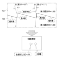
- a diffractive multifocal intraocular lens 58 may be applied to the eye model 70.
- the pseudo-anterior chamber 72 of the eyeball model 70 may be filled with a liquid 74 having the same refractive index as the anterior chamber water 64.
- the eyeball model 70 is an eyeball model used in an experimental stage for manufacturing a device (for example, an ophthalmic observation device or an ophthalmic laser treatment device) used for diagnosis or treatment of diabetic retinopathy or retinal detachment. It may be an eyeball model used for skill training for medical students or doctors to perform various ophthalmic operations or various examinations.
- a device for example, an ophthalmic observation device or an ophthalmic laser treatment device
- It may be an eyeball model used for skill training for medical students or doctors to perform various ophthalmic operations or various examinations.
- a and / or B is synonymous with "at least one of A and B". That is, “A and / or B” means that it may be only A, it may be only B, or it may be a combination of A and B. Further, in the present specification, when three or more matters are connected and expressed by "and / or", the same concept as “A and / or B" is applied.
Landscapes
- Health & Medical Sciences (AREA)
- Engineering & Computer Science (AREA)
- Ophthalmology & Optometry (AREA)
- Physics & Mathematics (AREA)
- Manufacturing & Machinery (AREA)
- General Physics & Mathematics (AREA)
- Optics & Photonics (AREA)
- Mechanical Engineering (AREA)
- General Health & Medical Sciences (AREA)
- Transplantation (AREA)
- Oral & Maxillofacial Surgery (AREA)
- Biomedical Technology (AREA)
- Heart & Thoracic Surgery (AREA)
- Vascular Medicine (AREA)
- Life Sciences & Earth Sciences (AREA)
- Animal Behavior & Ethology (AREA)
- Cardiology (AREA)
- Public Health (AREA)
- Veterinary Medicine (AREA)
- Diffracting Gratings Or Hologram Optical Elements (AREA)
Abstract
ブレーズド回折光学素子は、第1ブレーズド部材及び第2ブレーズド部材を有し、第1ブレーズド部材及び第2ブレーズド部材によって回折格子として機能するブレーズド回折格子対と、第1ブレーズド部材と第2ブレーズド部材との間に位置する中間層と、を備え、第1ブレーズド部材の屈折率をNaとし、中間層の屈折率をNとし、第2ブレーズド部材の屈折率をNbとしたとき、Na>N>Nbの大小関係が成立する。
Description
本開示の技術は、ブレーズド回折光学素子、及びブレーズド回折光学素子の製造方法に関する。
特開2011-107586号公報には、少なくとも3種類の材料からなる複数の回折格子を積層した回折光学素子が開示されている。特許文献1に記載の回折光学素子において、複数の回折格子は、互いに異なった材料M1A、M1Bより成り、格子部の格子側縁が、格子ピッチ方向に接触又は近接配置された2つの回折格子より成る第1の組合せ部と、少なくとも1つの材料が第1の組合せ部の2つの回折格子の材料と異なり、互いに異なった材料M2A、M2Bより成る2つの回折格子より成る第2の組合せ部とを有する。そして、第1の組合せ部を成す材料M1A、M1Bの、ある波長w(nm)における屈折率N1Aw、N1Bw、アッベ数ν1A、ν1B、第2の組合せ部を成す材料M2A、M2Bの、d線のおける屈折率N2Ad、N2Bd、アッベ数ν2A、ν2Bの値が適切に設定される。
本開示の技術に係る一つの実施形態は、第1ブレーズド部材と第2ブレーズド部材とを直接積層させた場合に比べ、入射された光に起因して生じるゴーストを抑制することができるブレーズド回折光学素子、及びブレーズド回折光学素子の製造方法を提供する。
本開示の技術に係る第1の態様は、ブレーズド回折光学素子であって、第1ブレーズド部材及び第2ブレーズド部材を有し、第1ブレーズド部材及び第2ブレーズド部材によって回折格子として機能するブレーズド回折格子対と、第1ブレーズド部材と第2ブレーズド部材との間に位置する中間層と、を備え、第1ブレーズド部材の屈折率をNaとし、中間層の屈折率をNとし、第2ブレーズド部材の屈折率をNbとしたとき、Na>N>Nbの大小関係が成立するブレーズド回折光学素子である。
本開示の技術に係る第2の態様は、第1ブレーズド部材及び第2ブレーズド部材の格子高さをhとし、中間層の厚さをtとし、θcを臨界角としたとき、h<t・tanθcの不等式、及びθc=asin(Nb/Na)の等式が成立する第1の態様に係るブレーズド回折光学素子である。
本開示の技術に係る第3の態様は、第1ブレーズド部材が、第1鋸歯状面を有し、第2ブレーズド部材は、第2鋸歯状面を有し、第1鋸歯状面及び第2鋸歯状面が、中間層を介して相補的に係合されている第1の態様又は第2の態様に係るブレーズド回折光学素子である。
本開示の技術に係る第4の態様は、第1ブレーズド部材が、第1鋸歯状面を有し、第2ブレーズド部材が、第2鋸歯状面を有し、第1鋸歯状面が、第1急斜面と第1急斜面よりも勾配が緩い第1緩斜面とで形成されており、第2鋸歯状面が、第2急斜面と第2急斜面よりも勾配が緩い第2緩斜面とで形成されており、中間層が、第1鋸歯状面と第2鋸歯状面との間において、第1急斜面と第2急斜面との間に配置されている第1の態様又は第2の態様に係るブレーズド回折光学素子である。
本開示の技術に係る第5の態様は、第1鋸歯状面が、第1急斜面と第1急斜面よりも勾配が緩い第1緩斜面とで形成されており、第2鋸歯状面が、第2急斜面と第2急斜面よりも勾配が緩い第2緩斜面とで形成されており、中間層が、第1鋸歯状面と第2鋸歯状面との間において、第1急斜面と第2急斜面との間に配置されている第3の態様に係るブレーズド回折光学素子である。
本開示の技術に係る第6の態様は、第1ブレーズド部材が、第1鋸歯状面を有し、第2ブレーズド部材が、第2鋸歯状面を有し、第1鋸歯状面が、第1急斜面と第1急斜面よりも勾配が緩い第1緩斜面とで形成されており、第2鋸歯状面が、第2急斜面と第2急斜面よりも勾配が緩い第2緩斜面とで形成されており、第1鋸歯状面と第2鋸歯状面との間において、第1急斜面と第2急斜面との間における中間層の厚さをtとし、第1ブレーズド部材及び第2ブレーズド部材の格子高さをhとし、θcを臨界角としたとき、h<t・tanθcの不等式、及びθc=asin(Nb/Na)の等式が成立する第1の態様に係るブレーズド回折光学素子である。
本開示の技術に係る第7の態様は、第1ブレーズド部材が、第1基準面を有し、第2ブレーズド部材が、第2基準面を有し、第1急斜面及び第1緩斜面が、第1基準面から立ち上がった面であり、第2急斜面及び第2緩斜面が、第2基準面から立ち上がった面であり、第1急斜面が、第1基準面に対して垂直であり、第2急斜面が、第2基準面に対して垂直である第4の態様から第6の態様の何れか1つの態様に係るブレーズド回折光学素子である。
本開示の技術に係る第8の態様は、第1鋸歯状面及び第2鋸歯状面が、中間層の厚み分ずれて係合されている第3の態様から第7の態様の何れか1つの態様に係るブレーズド回折光学素子である。
本開示の技術に係る第9の態様は、中間層が、第1ブレーズド部材側から第2ブレーズド部材側にかけて小さくなる屈折率を有する複数の層からなる第1の態様から第8の態様の何れか1つの態様に係るブレーズド回折光学素子である。
本開示の技術に係る第10の態様は、中間層が、膜状に形成されている第1の態様から第9の態様の何れか1つの態様に係るブレーズド回折光学素子である。
本開示の技術に係る第11の態様は、第1ブレーズド部材のブレーズ角及び第2ブレーズド部材のブレーズ角が同一である第1の態様から第10の態様の何れか1つの態様に係るブレーズド回折光学素子である。
本開示の技術に係る第12の態様は、第1ブレーズド部材の格子高さと第2ブレーズド部材の格子高さが同一である第1の態様から第11の態様の何れか1つの態様に係るブレーズド回折光学素子である。
本開示の技術に係る第13の態様は、ブレーズド回折光学素子であって、ブレーズド部材と、ブレーズド部材上に設けられた層と、を備え、層の屈折率が、ブレーズド部材の屈折率と、ブレーズド部材の周囲の環境の屈折率との間である、ブレーズド回折光学素子である。
本開示の技術に係る第14の態様は、周囲の環境が、眼内にある前房水であり、層の屈折率は、ブレーズド部材の屈折率と、前房水の屈折率との間にある、第13の態様に係るブレーズド回折光学素子である。
本開示の技術に係る第15の態様は、前房水の屈折率をAとし、表層の屈折率をBとし、ブレーズド部材の屈折率をCとしたとき、A<B<Cの大小関係が成立する第14の態様に係るブレーズド回折光学素子である。
本開示の技術に係る第16の態様は、ブレーズド部材の格子高さをhとし、層の厚さをtとし、θcを臨界角としたとき、h<t・tanθcの不等式、及びθc=asin(A/C)の等式が成立する第15の態様に係るブレーズド回折光学素子である。
本開示の技術に係る第17の態様は、ブレーズド部材が、鋸歯状面を有し、層が、鋸歯状面上に、鋸歯状面に相当する形状に形成されている第15の態様又は第16の態様に係るブレーズド回折光学素子である。
本開示の技術に係る第18の態様は、鋸歯状面が、急斜面と急斜面よりも勾配が緩い緩斜面とで形成されている第17の態様に係るブレーズド回折光学素子である。
本開示の技術に係る第19の態様は、ブレーズド部材が、基準面を有し、急斜面及び緩斜面が、基準面から立ち上がった面であり、急斜面が、基準面に対して垂直である、第18の態様に係るブレーズド回折光学素子である。
本開示の技術に係る第20の態様は、鋸歯状面及び前房水が、層の厚み分ずれて接触している第17の態様から第19の態様の何れか1つの態様に係るブレーズド回折光学素子である。
本開示の技術に係る第21の態様は、表層が、前房水側からブレーズド部材側にかけて大きくなる屈折率を有する複数の層からなる第14の態様から第20の態様の何れか1つの態様に係るブレーズド回折光学素子である。
本開示の技術に係る第22の態様は、表層が、膜状に形成されている第13の態様から第21の態様の何れか1つの態様に係るブレーズド回折光学素子である。
本開示の技術に係る第23の態様は、ブレーズド回折光学素子の製造方法であって、第1ブレーズド部材を形成する工程と、第1ブレーズド部材のブレーズド部に中間層を形成する工程と、中間層の第1ブレーズド部材側と反対側に第1ブレーズド部材と対を成す第2ブレーズド部材を形成する工程と、を備え、第1ブレーズド部材の屈折率をNaとし、中間層の屈折率をNとし、第2ブレーズド部材の屈折率をNbとしたとき、Na>N>Nbの大小関係が成立するブレーズド回折光学素子の製造方法である。
本開示の技術に係る第24の態様は、中間層を形成する工程が、中間層をスピンコートを用いて形成する工程である第23の態様に係るブレーズド回折光学素子の製造方法である。
本開示の技術に係る第25の態様は、第1ブレーズド部材及び第2ブレーズド部材の格子高さをhとし、中間層の厚さをtとし、θcを臨界角としたとき、h<t・tanθcの不等式、及びθc=asin(Nb/Na)の等式が成立する厚さの中間層を形成する第23の態様又は第24の態様に係るブレーズド回折光学素子の製造方法である。
本開示の技術に係る第26の態様は、第1ブレーズド部材が、第1鋸歯状面を有し、第2ブレーズド部材が、第2鋸歯状面を有し、第2ブレーズド部材を形成する工程において、第1鋸歯状面と第2鋸歯状面とを中間層の厚み分ずらして係合させる第23の態様から第25の態様の何れか1つの態様に係るブレーズド回折光学素子の製造方法である。
以下、添付図面に従って本開示の技術に係る積層型ブレーズド回折光学素子、及び積層型ブレーズド回折光学素子の製造方法の実施形態の一例について説明する。
なお、本明細書の説明において、「垂直」とは、完全な垂直の他に、本開示の技術が属する技術分野で一般的に許容される誤差であって、本開示の技術の趣旨に反しない程度の誤差を含めた意味合いでの垂直を指す。また、本明細書の説明において、「直交」とは、完全な直交の他に、本開示の技術が属する技術分野で一般的に許容される誤差であって、本開示の技術の趣旨に反しない程度の誤差を含めた意味合いでの直交を指す。また、本明細書の説明において、「平行」とは、完全な平行の他に、本開示の技術が属する技術分野で一般的に許容される誤差であって、本開示の技術の趣旨に反しない程度の誤差を含めた意味合いでの平行を指す。また、本明細書の説明において、「同一」とは、完全な同一の他に、本開示の技術が属する技術分野で一般的に許容される誤差であって、本開示の技術の趣旨に反しない程度の誤差を含めた意味合いでの同一を指す。
<接合光学素子の全体構成>
一例として図1に示すように、接合光学素子10は、一対のレンズ及び積層型ブレーズド回折光学素子12を備えている。接合光学素子10は、例えば、光学装置(例えば、デジタルカメラ、プロジェクタ、及び顕微鏡等)のレンズ、及び視力矯正具(例えば、眼鏡及びコンタクトレンズ)のレンズとして利用される。
一例として図1に示すように、接合光学素子10は、一対のレンズ及び積層型ブレーズド回折光学素子12を備えている。接合光学素子10は、例えば、光学装置(例えば、デジタルカメラ、プロジェクタ、及び顕微鏡等)のレンズ、及び視力矯正具(例えば、眼鏡及びコンタクトレンズ)のレンズとして利用される。
接合光学素子10に含まれる一対のレンズはガラス製のレンズであり、紫外線UV(図8、図10及び図13参照)を透過する。図1に示す例では、一対のレンズとして、平凸レンズ14(図2も参照)及び両凹レンズ16(図3も参照)が示されている。ここでは、一対のレンズとして、平凸レンズ14と両凹レンズ16との組み合わせを例示しているが、これはあくまでも一例に過ぎず、一対のレンズは、他種類のレンズの組み合わせ(例えば、両凸レンズと平凹レンズとの組み合わせ)であってもよい。また、一対のレンズはガラス製である必要はなく、樹脂製であってもよい。
なお、以下では、説明の便宜上、平凸レンズ14及び両凹レンズ16の厚み方向をZ方向とし、平凸レンズ14及び両凹レンズ16の幅方向をX方向とし、平凸レンズ14及び両凹レンズ16の図中奥行方向、すなわち、Z方向及びX方向に直交する方向をY方向として説明する。
積層型ブレーズド回折光学素子12は、本開示の技術に係る「ブレーズド回折光学素子」の一例であり、ブレーズド回折格子対18を備えている。ブレーズド回折格子対18は、第1ブレーズド部材20及び第2ブレーズド部材22を有しており、第1ブレーズド部材20及び第2ブレーズド部材22によって回折格子として機能する。
一例として図1に示すように、第1ブレーズド部材20は、Z方向に表面と裏面を有しており、裏面が平凸レンズ14の凸面14A(図2も参照)に接合されている。第1ブレーズド部材20の表面は第1鋸歯状面20Aである。第1鋸歯状面20Aは、断面視鋸歯状に形成されている。一例として図4に示すように、第1ブレーズド部材20をZ方向下側から観察した場合、第1鋸歯状面20Aには同心円状に楔状溝26が形成されている。
一例として図1に示すように、第2ブレーズド部材22は、Z方向に表面と裏面を有しており、裏面が両凹レンズ16の一方の凹面16A(図3も参照)に接合されている。第2ブレーズド部材22の表面は第2鋸歯状面22Aである。第2鋸歯状面22Aは、断面視鋸歯状に形成されている。一例として図4に示すように、第2ブレーズド部材22をZ方向上側から観察した場合、第2鋸歯状面22Aには同心円状に楔状溝28が形成されている。
一例として図1に示すように、積層型ブレーズド回折光学素子12は、中間層24を備えている。中間層24は、第1ブレーズド部材20と第2ブレーズド部材22との間に位置している。
ここで、第1ブレーズド部材20の屈折率をNaとし、中間層24の屈折率をNとし、第2ブレーズド部材22の屈折率をNbとしたとき、“Na>N>Nb”の大小関係が成立する。図1に示す例では、屈折率Naの一例として、“1.58”が示されており、屈折率Nの一例として、“1.57”が示されており、屈折率Nbの一例として、“1.56”が示されている。
<積層型ブレーズド回折光学素子の製造方法>
図5には、積層型ブレーズド回折光学素子12の製造方法の一例が示されている。図5に示す製造方法は、ステップST100の第1ブレーズド部材形成工程と、ステップST102の中間層形成工程と、ステップST104の第2ブレーズド部材形成工程と、を含む。
図5には、積層型ブレーズド回折光学素子12の製造方法の一例が示されている。図5に示す製造方法は、ステップST100の第1ブレーズド部材形成工程と、ステップST102の中間層形成工程と、ステップST104の第2ブレーズド部材形成工程と、を含む。
ステップST100では、第1ブレーズド部材20が形成される。ステップST102では、第1ブレーズド部材20の第1鋸歯状面20Aに中間層24が形成される。なお、第1鋸歯状面20Aは、本開示の技術に係る「ブレーズド部」の一例である。ステップST104では、中間層24の第1ブレーズド部材20側と反対側に第1ブレーズド部材20と対をなす第2ブレーズド部材22が形成される。以下、第1ブレーズド部材形成工程、中間層形成工程、及び第2ブレーズド部材形成工程について、より詳しく説明する。
<第1ブレーズド部材形成工程>
第1ブレーズド部材20を作る場合、一例として図6に示すように、キャビティ34を用いる。キャビティ34は、第1鋸歯状面20Aの成型用の金型である。キャビティ34の中央部には、窪み36が形成されている。窪み36は、ボウル状に形成されている。窪み36の表面は、同心円状面36Aである。同心円状面36Aは、窪み36の底の中央を中心として同心円状に楔状溝(例えば、図4に示す楔状溝に対応する溝)が形成された面である。同心円状面36Aの大きさ及び形状は、第2鋸歯状面22Aに対応している。すなわち、同心円状面36Aは、第2鋸歯状面22Aと同一の大きさ及び形状で形成されている。
第1ブレーズド部材20を作る場合、一例として図6に示すように、キャビティ34を用いる。キャビティ34は、第1鋸歯状面20Aの成型用の金型である。キャビティ34の中央部には、窪み36が形成されている。窪み36は、ボウル状に形成されている。窪み36の表面は、同心円状面36Aである。同心円状面36Aは、窪み36の底の中央を中心として同心円状に楔状溝(例えば、図4に示す楔状溝に対応する溝)が形成された面である。同心円状面36Aの大きさ及び形状は、第2鋸歯状面22Aに対応している。すなわち、同心円状面36Aは、第2鋸歯状面22Aと同一の大きさ及び形状で形成されている。
窪み36には、気泡が入り込まないように第1ブレーズド部材20用の液状の紫外線硬化樹脂38が流し込まれる。なお、同心円状面36Aの大きさ及び形状は、後の工程で窪み36内の紫外線硬化樹脂38に対して紫外線UV(図8参照)が照射された場合の紫外線硬化樹脂38の収縮率を考慮して設計されている。
窪み36に紫外線硬化樹脂38が流し込まれると、次に、一例として図7に示すように、凸面14Aを窪み36に被せるように平凸レンズ14を窪み36に入れ込む。すなわち、凸面14Aを同心円状面36Aに正対させた状態で凸面14Aから窪み36内の紫外線硬化樹脂38に平凸レンズ14を沈める。窪み36から溢れた紫外線硬化樹脂38は拭き取られる。
次に、一例として図8に示すように、窪み36に平凸レンズ14が入れられた状態で、紫外線照射装置40が、平凸レンズ14の平面14B(凸面14Aと反対側の面)側から紫外線UVを照射する。紫外線UVは、平凸レンズ14を透過して窪み36内の紫外線硬化樹脂38に照射される。これにより、紫外線硬化樹脂38が硬化して、凸面14Aに第1ブレーズド部材20が形成される(図1、図4及び図9参照)。
<中間層形成工程>
中間層24を作る場合、先ず、平凸レンズ14がキャビティ34から取り出される。そして、一例として図9に示すように、平凸レンズ14は、第1鋸歯状面20Aを上方に向けた状態でスピンコータ42の円盤台42Aの上面42A1に設置される。平凸レンズ14の平面14B(図8参照)の中心は、上面42A1の中心に位置合わせされ、平凸レンズ14が上面42A1に取り付けられる。
中間層24を作る場合、先ず、平凸レンズ14がキャビティ34から取り出される。そして、一例として図9に示すように、平凸レンズ14は、第1鋸歯状面20Aを上方に向けた状態でスピンコータ42の円盤台42Aの上面42A1に設置される。平凸レンズ14の平面14B(図8参照)の中心は、上面42A1の中心に位置合わせされ、平凸レンズ14が上面42A1に取り付けられる。
上面42A1に対する平凸レンズ14の取り付け方法としては、例えば、吸着による取り付け方法及び/又は押さえ付け部材による取り付け方法等が挙げられる。
次に、円盤台42Aの上面42A1に平凸レンズ14が取り付けられた状態で、中間層24用の液状の紫外線硬化樹脂44が第1鋸歯状面20Aの中心に向けて落とされる。紫外線硬化樹脂44は、アクリル系又はエポキシ系の紫外線硬化樹脂であることが好ましい。また、紫外線硬化樹脂に代えて熱硬化樹脂を適用してもよい。また、メタクリレート系高分子の置換基Rを変化させることにより中間層24の屈折率を調整することも可能である。また、複数種類の材料の混合比を調整することで中間層24の屈折率を調整するようにしてもよい。
次に、紫外線硬化樹脂44が第1鋸歯状面20Aの中心に向けて落とされた状態、円盤台42Aを高速回転させる。円盤台42Aの回転により紫外線硬化樹脂44に遠心力が加わり、紫外線硬化樹脂44が第1鋸歯状面20Aの全体に拡散塗布される。
次に、一例として図10に示すように、紫外線照射装置40が、第1鋸歯状面20Aの全体に拡散塗布された紫外線硬化樹脂44の全体に対して紫外線UVを照射する。これにより、第1鋸歯状面20A上で紫外線硬化樹脂44が硬化され、第1鋸歯状面20Aに中間層24が膜状に形成される。なお、ここでは、中間層24が単層であるため、1回の成膜工程で足りるが、中間層24を複層化させる場合には、同様の成膜工程が層数分だけ繰り返し行われる。
<第2ブレーズド部材形成工程>
第2ブレーズド部材22を作る場合、一例として図11に示すように、両凹レンズ16の凹面16Aには、気泡が入り込まないように第2ブレーズド部材22用の液状の紫外線硬化樹脂48が流し込まれる。
第2ブレーズド部材22を作る場合、一例として図11に示すように、両凹レンズ16の凹面16Aには、気泡が入り込まないように第2ブレーズド部材22用の液状の紫外線硬化樹脂48が流し込まれる。
次に、一例として図12に示すように、中間層24を凹面16Aに被せるように平凸レンズ14を両凹レンズ16の凹面16A側に入れ込む。すなわち、中間層24を凹面16Aに正対させた状態で中間層24から両凹レンズ16の凹面16A側の紫外線硬化樹脂48に平凸レンズ14を沈める。凹面16Aから溢れた紫外線硬化樹脂48は拭き取られる。
次に、一例として図13に示すように、両凹レンズ16の凹面16A側に平凸レンズ14が入れられた状態で、紫外線照射装置50が、両凹レンズ16の他方の凹面16B(凹面16Aとは反対側の面)側から紫外線UVを照射する。紫外線UVは、両凹レンズ16を透過して紫外線硬化樹脂48に照射される。これにより、紫外線硬化樹脂48が硬化して、凹面16A上に第2ブレーズド部材22が形成される。
<従来の積層型ブレーズド回折光学素子>
図14及び図15には、従来の回折光学素子の一例として、中間層を含まない積層型ブレーズド回折光学素子、すなわち、一対のブレーズド部材が直接係合している積層型ブレーズド回折光学素子100が示されている。
図14及び図15には、従来の回折光学素子の一例として、中間層を含まない積層型ブレーズド回折光学素子、すなわち、一対のブレーズド部材が直接係合している積層型ブレーズド回折光学素子100が示されている。
一例として図14に示すように、積層型ブレーズド回折光学素子100において、一対のブレーズド部材は、第1ブレーズド部材20に相当する第1ブレーズド部材102と、第2ブレーズド部材22に相当する第2ブレーズド部材104によって形成されている。
第1ブレーズド部材102は、第1鋸歯状面20Aに相当する第1鋸歯状面106を有する。第1ブレーズド部材102は、第1基準面102Aを有する。第1基準面102Aは、仮想的に設定された面であり、例えば、凸面14A(図1参照)に相当する面に対して平行な面である。
第1鋸歯状面106は、第1急斜面106A及び第2緩斜面106Bによって形成されている。第1緩斜面106Bは、第1急斜面106Aよりも第1基準面102Aに対して勾配が緩い面である。第1急斜面106Aは、第1基準面102Aに対して垂直な面であり、第1基準面102Aからの第1急斜面106Aの高さが、第1ブレーズド部材102の格子高さである。なお、第1急斜面106Aは、第1基準面102Aに対して垂直でなくてもよい。なぜならば、使用される光学系において、主たる入射光線の方向に対し、最も回折効率が高くなるように第1急斜面106Aの角度が適切に決定されるからである。
第2ブレーズド部材104は、第2鋸歯状面22Aに相当する第2鋸歯状面108を有する。第2ブレーズド部材102は、第2基準面104Aを有する。第2基準面104Aは、仮想的に設定された面であり、例えば、凹面16A(図1参照)に相当する面に対して平行な面である。
第2鋸歯状面22Aは、第2急斜面108A及び第2緩斜面108Bによって形成されている。第2緩斜面108Bは、第2急斜面108Aよりも第2基準面104Aに対して勾配が緩い面である。第2急斜面108Aは、第2基準面104Aに対して垂直な面であり、第2基準面104Aからの第2急斜面108Aの高さが、第2ブレーズド部材104の格子高さである。
第1ブレーズド部材102の第1鋸歯状面106は、第2ブレーズド部材104の第2鋸歯状面108に直接係合している。この場合、第1急斜面106Aは、第2急斜面108Aに直接接触しており、第1緩斜面106Bは、第2緩斜面108Bに直接接触している。なお、図14及び図15に示すでは、説明の便宜上、第1急斜面106Aと第2急斜面108Aとを区別して説明する必要がない場合、符号を付さずに「急斜面」と称し、第1緩斜面106Bと第2緩斜面108Bとを区別して説明する必要がない場合、符号を付さずに「緩斜面」と称する。
第1ブレーズド部材102の屈折率は、第2ブレーズド部材104の屈折率よりも高く、図14に示す例では、第1ブレーズド部材102の屈折率として“1.58”が示されており、第2ブレーズド部材104の屈折率として“1.56”が示されている。
この場合、被写体光が第1ブレーズド部材102(屈折率が“1.58”の層)から緩斜面を介して第2ブレーズド部材104(屈折率が“1.56”の層)に入射され、再び、急斜面を介して第1ブレーズド部材102に入射されてから、緩斜面を介して第2ブレーズド部材104に入射される。ここで、被写体光が急斜面に入射される角度θ1次第で、急斜面で被写体光が屈折する。図14に示す例では、被写体光が急斜面に入射される角度θ1は5度であり、急斜面で被写体光が屈折する角度θ2は7度である。この結果、イメージセンサによって撮像されることで得られる撮像画像には、被写体光の屈折によるゴーストが写り込んでしまう。
図14に示す例では、第1ブレーズド部材102から緩斜面を透過した被写体光が急斜面に入射されているが、図15に示す例では、第1ブレーズド部材102に入射された被写体光が緩斜面を介さずに急斜面に直接照射されている。この場合、角度θ1次第で、急斜面で被写体光が全反射する。例えば、角度θ1が0度以上11度以下の範囲の場合、被写体光は急斜面で全反射される。この結果、イメージセンサによって撮像されることで得られる撮像画像には、被写体光の全反射によるゴーストが写り込んでしまう。
<積層型ブレーズド回折光学素子の詳細>
このような事情に鑑み、一例として図18に示すように、積層型ブレーズド回折光学素子12は、ブレーズド回折格子対18及び中間層24を備えている。屈折率Nの中間層24は、屈折率Naの第1ブレーズド部材20と屈折率Nbの第2ブレーズド部材22との間に位置している。また、屈折率Naの第1ブレーズド部材20、屈折率Nbの第2ブレーズド部材22、及び屈折率Nの中間層24の間において、“Na>N>Nb”の大小関係が成立している。
このような事情に鑑み、一例として図18に示すように、積層型ブレーズド回折光学素子12は、ブレーズド回折格子対18及び中間層24を備えている。屈折率Nの中間層24は、屈折率Naの第1ブレーズド部材20と屈折率Nbの第2ブレーズド部材22との間に位置している。また、屈折率Naの第1ブレーズド部材20、屈折率Nbの第2ブレーズド部材22、及び屈折率Nの中間層24の間において、“Na>N>Nb”の大小関係が成立している。
また、第1鋸歯状面20Aは、第1急斜面20A1と第1急斜面20A1よりも勾配が緩い第1緩斜面20A2とで形成されている。第2鋸歯状面22Aは、第2急斜面22A1と第2急斜面22A1よりも勾配が緩い第2緩斜面22A2とで形成されている。そして、中間層24は、第1鋸歯状面20Aと第2鋸歯状面22Aとの間において、第1急斜面20A1と第2急斜面22A1との間に配置されている。
また、第1鋸歯状面20A及び第2鋸歯状面22Aは、中間層24を介して相補的に係合されている。すなわち、第1急斜面20A1と第2急斜面22A1とがX方向に沿って交互に配置されるように第1鋸歯状面20Aと第2鋸歯状面22Aとが中間層24を介して係合している。
また、第1ブレーズド部材20は、第1基準面52を有し、第2ブレーズド部材22は、第2基準面54を有する。第1基準面52及び第2基準面54は仮想的に設定された面である。第1基準面52は、凸面14A(図1参照)に対して平行な面であり、第2基準面54は、凹面16A(図1参照)に対して平行な面である。
第1急斜面20A1及び第1緩斜面20A2は、第1基準面52から立ち上がった面であり、第2急斜面22A1及び第2緩斜面22A2は、第2基準面54から立ち上がった面である。第1急斜面20A1は、第1基準面52に対して垂直であり、第2急斜面22A1は、第2基準面54に対して垂直である。
また、第1鋸歯状面20A及び第2鋸歯状面22Aは、中間層24の厚み分ずれて係合されている。すなわち、第1鋸歯状面20A及び第2鋸歯状面22Aは、中間層24を介して係合している。
また、第1ブレーズド部材20のブレーズ角及び第2ブレーズド部材22のブレーズ角は同一である。また、第1ブレーズド部材20の格子高さと第2ブレーズド部材の格子高さは同一である。
一例として図17に示すように、積層型ブレーズド回折光学素子12では、被写体光を第1ブレーズド部材20から中間層24を介して第2ブレーズド部材22を透過させるために、第1ブレーズド部材20と第2ブレーズド部材22の格子高さをhとし、中間層24の厚さをtとし、臨界角をθcとしたとき、h<t・tanθの不等式、及びθc=asin(Nb/Na)の等式が成立するように、格子高さh及び中間層24の厚さtが定められている。
なお、中間層24の厚さtは、第1緩斜面20A2と第2緩斜面22A2との間の厚さ、及び第1急斜面20A1と第2急斜面22A1との間の厚さを表している。
また、ここで、臨界角とは、積層型ブレーズド回折光学素子12の第1ブレーズド部材20側から被写体光を照射した場合に被写体光を第2ブレーズド部材22から透過させることができない入射角の最小値を指す。ここで、被写体光を透過させることができないとは、例えば、屈折率が異なる層(媒体)間で、被写体光が全反射してしまって被写体光が層間を透過しないことを意味する。入射角とは、隣接する層の接合面(例えば、第1ブレーズド部材20と中間層24との接合面、及び中間層24と第2ブレーズド部材20との接合面)に対して入射される被写体光の光路の角度を指す。図17に示す例において、隣接する層の接合面に対して入射される被写体光の光路の角度は、接合面の法線に対する角度である。
<積層型ブレーズド回折光学素子の作用及び効果>
次に、積層型ブレーズド回折光学素子12の作用について説明する。
次に、積層型ブレーズド回折光学素子12の作用について説明する。
“第1の媒体の屈折率<第2の媒体の屈折率”という大小関係が成立している第1の媒体及び第2の媒体間において、被写体光が第2の媒体側から第1の媒体側に向けて照射された場合、臨界角θc=asin{(第1の媒体の屈折率)/(第2の媒体の屈折率)}以上の角度で被写体光は全反射する。
図17に示す例において、第1ブレーズド部材20及び中間層24間の臨界角θcは、第1ブレーズド部材20及び第2ブレーズド部材22間の臨界角θcよりも大きい。そのため、第1ブレーズド部材20から中間層24に対して入射される被写体光の光路の角度が、第1ブレーズド部材20及び第2ブレーズド部材22間での臨界角θc以上であっても、第1ブレーズド部材20から中間層24に対して入射される被写体光は中間層24で全反射せずに屈折する。屈折した被写体光は、第2ブレーズド部材22に到達する前に、中間層24のうちの図17中の下面56(中間層24と第2ブレーズド部材22との接合面(境界面))に到達し、下面56に隣接する第2ブレーズド部材22に入射する。
なぜならば、h<t・tanθの不等式、及びθc=asin(Nb/Na)の等式が成立するように、格子高さh及び中間層24の厚さtが定められているので、被写体光が、全反射する前に中間層24の図中下面56に到達するからである。
ここで、図17に示す例では第1ブレーズド部材20と中間層24との臨界角θc1は83.6度となる。このため、中間層24が存在しない場合の臨界角θcである79度を超える入射角を有する被写体光であっても、入射角が83.6度よりも小さい場合は第1ブレーズド部材20と中間層24との間で全反射しない。すなわち、第1ブレーズド部材20と中間層24との接合面に対して入射される被写体光は、79度<角度θ<83.6度の範囲では、第1ブレーズド部材20と中間層24との接合面で全反射することなく中間層24に入射する。そして、中間層24に入射された被写体光は、中間層24の図中下面56から第2ブレーズド部材22に入射する。
以上説明したように、積層型ブレーズド回折光学素子12は、第1ブレーズド部材20及び第2ブレーズド部材22によって回折格子として機能するブレーズド回折格子対18と、第1ブレーズド部材20と第2ブレーズド部材22との間に位置する中間層24と、を備えている。そして、屈折率Naの第1ブレーズド部材20、屈折率Nbの第2ブレーズド部材22、及び屈折率Nの中間層24の間において、“Na>N>Nb”の大小関係が成立している。従って、本構成によれば、第1ブレーズド部材20と第2ブレーズド部材22とを直接積層させた場合に比べ、入射された光の全反射に起因して生じるゴーストを抑制することができる。また、本構成によれば、中間層24が存在することに起因して、光が完全に屈折するまでに要する距離が長くなるため、完全に屈折する前に下面56(図17参照)に到達するため、入射された光の屈折に起因して生じるゴーストも抑制することができる。
また、積層型ブレーズド回折光学素子12では、第1ブレーズド部材20と第2ブレーズド部材22の格子高さをhとし、中間層24の厚さをtとし、臨界角をθcとしたとき、h<t・tanθの不等式、及びθc=asin(Nb/Na)の等式が成立する。従って、本構成によれば、h<t・tanθcの不等式、及びθc=asin(Nb/Na)の等式が成立しない条件を用いて格子高さ及び中間層24の厚さを定める場合に比べ、ゴーストが発生し難い格子高さ及び中間層24の厚さとして、最適な格子高さ及び最適な中間層24の厚さを容易に定めることができる。
また、積層型ブレーズド回折光学素子12では、第1鋸歯状面20A及び第2鋸歯状面22Aが、中間層24を介して相補的に係合されている。従って、本構成によれば、第1鋸歯状面20Aと第2鋸歯状面22Aとが中間層24を介して相補的に係合していない場合に比べ、入射された光に起因して生じるゴーストを抑制することができる。
また、積層型ブレーズド回折光学素子12では、中間層24が、第1鋸歯状面20Aと第2鋸歯状面22Aとの間において、第1急斜面20A1と第2急斜面22A1との間に配置されている。従って、本構成によれば、第1急斜面20A1と第2急斜面22A1との間に中間層24が配置されていない場合に比べ、第1急斜面20A1及び第2急斜面22A1に入射された光に起因して生じるゴーストを抑制することができる。
また、積層型ブレーズド回折光学素子12では、第1鋸歯状面20Aと第2鋸歯状面22Aとの間において、第1急斜面20A1と第2急斜面22A1との間に中間層24の厚さをtとし、第1ブレーズド部材20と第2ブレーズド部材22の格子高さをhとし、臨界角をθcとしたとき、h<t・tanθの不等式、及びθc=asin(Nb/Na)の等式が成立する。従って、本構成によれば、h<t・tanθcの不等式、及びθc=asin(Nb/Na)の等式が成立しない条件を用いて、格子高さと、第1急斜面20A1と第2急斜面22A1との間の中間層24の厚さを定める場合に比べ、ゴーストが発生し難い格子高さ、及びゴーストが発生し難い第1急斜面20A1と第2急斜面22A1との間の中間層24の厚さとして、最適な格子高さ及び最適な中間層24の厚さを容易に定めることができる。
また、積層型ブレーズド回折光学素子12では、第1急斜面20A1が第1基準面52に対して垂直であり、第2急斜面22A1が第2基準面54に対して垂直である。従って、本構成によれば、第1急斜面20A1が第1基準面52に対して垂直ではなく、かつ、第2急斜面22A1が第2基準面52に対して垂直でない場合に比べ、第1急斜面20A1及び第2急斜面22A1に入射された光に起因して生じるゴーストを抑制することができる。
また、積層型ブレーズド回折光学素子12では、第1鋸歯状面20Aと第2鋸歯状面22Aは、中間層24の厚み分ずれて係合されている。従って、本構成によれば、第1鋸歯状面20Aと第2鋸歯状面22Aとが中間層24の厚み分ずれて係合されていない場合に比べ、入射された光に起因して生じるゴーストを抑制することができる。
また、積層型ブレーズド回折光学素子12では、中間層24が膜状に形成されている。従って、本構成によれば、積層型ブレーズド回折光学素子12の薄型化に寄与することができる。
また、積層型ブレーズド回折光学素子12では、第1ブレーズド部材20のブレーズ角及び第2ブレーズド部材22のブレーズ角が同一である。従って、本構成によれば、第1ブレーズド部材20のブレーズ角と第2ブレーズド部材22のブレーズ角とが不揃いの場合に比べ、入射された光に起因して生じるゴーストを抑制することができる。
また、積層型ブレーズド回折光学素子12では、第1ブレーズド部材20の格子高さと第2ブレーズド部材の格子高さが同一である。従って、本構成によれば、第1ブレーズド部材20の格子高さと第2ブレーズド部材の格子高さとが不揃いの場合に比べ、入射された光に起因して生じるゴーストを抑制することができる。
また、積層型ブレーズド回折光学素子12の製造方法に含まれる中間層形成工程には、中間層24をスピンコートを用いて形成する工程が含まれる。従って、本構成によれば、中間層24を蒸着する場合に比べ、中間層24を厚さが均一な膜状に容易に形成することができる。
なお、上記実施形態では、第1緩斜面20A2の全面と第2緩斜面22A2の全面との間に中間層24を介在させる形態例を挙げて説明したが、本開示の技術はこれに限定されない。例えば、図18に示すように、第1鋸歯状面20Aのうちの少なくとも第1急斜面20A1と第2鋸歯状面22Aのうちの少なくとも第2急斜面22A1との間に中間層24を介在させるようにしてもよい。これにより、第1急斜面20A1と第2急斜面22A1との間に中間層24が配置されていない場合に比べ、第1急斜面20A1及び第2急斜面22A1に入射された光に起因して生じるゴーストを抑制することができる。
また、上記実施形態では、中間層24が単層である形態例について説明したが、本開示の技術はこれに限定されず、中間層24が複層化構造であってもよい。図19に示す例では、中間層24は、第1層30及び第2層32によって形成されている。第1層30及び第2層32は積層している。第1層30は第1鋸歯状面20Aに接合されており、第2層32は第2鋸歯状面22Aに接合されている。すなわち、凸面14A(図1参照)から凹面16A(図1参照)にかけて、第1ブレーズド部材20、第1層30、第2層32、及び第2ブレーズド部材22が順に積層されている。
ここで、第1層30の屈折率をN1とし、第2層32の屈折率をN2としたとき、第1ブレーズド部材20の屈折率Na、第1層30の屈折率N1、第2層32の屈折率N2、及び第2ブレーズド部材の屈折率Nb間において、“Na>N1>N2>Nb”の大小関係が成立している。このように、中間層24において、細かく屈折率を変化させると、各界面での全反射角度が大きくなるので、全反射しない角度範囲が広がり好適である。従って、本構成によれば、中間層24が1層からなる場合に比べ、中間層24に入射される光の屈折を段階的に細かく制御することができる。なお、第1層30及び第2層32は、あくまでも一例に過ぎず、第1ブレーズド部材20側から第2ブレーズド部材22側にかけて小さくなる屈折率を有する複数の層であれば、3層以上であってもよい。また、中間層24は、複数の層に区切られる必要はなく、屈折率が連続的に変化してもよい。
また、上記実施形態では、両凹レンズ16に中間層24を浸して紫外線UVを照射することで中間層24に対して第2ブレーズド部材22及び両凹レンズ16が一体的に接合される形態例を挙げて説明したが、本開示の技術はこれに限定されない。例えば、第2ブレーズド部材22の成型用のキャビティを用いて、先ず、中間層24に対して第2ブレーズド部材22を接合させ、その次に、第2ブレーズド部材22に両凹レンズ16の凹面16Aが接合させてもよい。
また、上記実施形態では、凹面16B側から紫外線UVが照射される形態例(図13参照)を挙げて説明したが、本開示の技術はこれに限定されない。例えば、平凸レンズ14の平面14B側から紫外線UVが照射されるようにしてもよい。この場合、第1ブレーズド部材20及び中間層24を透過可能な波長の紫外線UVが照射されるようにすればよい。
また、上記実施形態では、紫外線硬化樹脂38、44、46及び48を例示したが、本開示の技術はこれに限定されない。例えば、紫外線とは異なる波長光に反応して硬化する光硬化樹脂であってもよいし、熱硬化樹脂であってもよい。
また、上記実施形態では、接合光学素子10に対して一対のレンズを適用したが、本開示の技術はこれに限定されず、光を透過する光学素子であれば、レンズ以外の光学素子であってもよい。
また、上記実施形態では、スピンコートによる成膜方法を例示したが、本開示の技術はこれに限定されず、スプレーコート又はインクジェット等による成膜方法であってもよい。また、SiO2、TiO2、又はMgF2等の無機材料を用いて中間層24を作ってもよい。無機材料をコートする場合は蒸着等を利用することが好ましい。
また、上記実施形態では、被写体光が入射される側の第1ブレーズド部材20から第2ブレーズド部材22にかけて形成されている複数の層(媒体)の屈折率が第1ブレーズド部材20側から第2ブレーズド部材22側にかけて小さくなる形態例を挙げて説明したが、本開示の技術はこれに限定されず、被写体光の入射方向に関わらず、第2ブレーズド部材22側から第1ブレーズド部材20側にかけて複数の層の屈折率が小さくなるようにしても上記実施形態と同様の効果が得られる。
また、上記実施形態では、接合光学素子10について説明したが、本開示の技術はこれに限定されず、本開示の技術を、回折型多焦点眼内レンズに適用することも可能である。一例として図20に示すように、本開示の技術に係る「ブレーズド回折光学素子」の一例である回折型多焦点眼内レンズ58は、眼球60内(以下、「「眼内」とも称する)に組み込まれて用いられる。例えば、白内障によって濁った水晶体に代えて、眼内に埋め込まれる。図20に示す例では、水晶体に代えて回折型多焦点眼内レンズ58が配置されている。このように、回折型多焦点眼内レンズ58は、水晶体に代えて用いられるので、回折型多焦点眼内レンズ58の表面(前房水に接触する側の面)には、ブレーズドの回折格子が刻まれており、回折型多焦点眼内レンズ58の表面は、前房62内に満たされている房水(以下、「前房水」とも称する)64に直接接触する。
回折型多焦点眼内レンズ58は、ブレーズド部材66及び表層68を備えている。ブレーズド部材66は、上記実施形態で説明した第2ブレーズド部材22に相当する部材であり、表層68は、上記実施形態で説明した中間層24に相当する部材である。なお、表層68は、本開示の技術に係る「層」の一例である。
ブレーズド部材66には、上記実施形態で説明した第2鋸歯状面22Aに相当する鋸歯状面66Aが形成されている。鋸歯状面66Aは、急斜面66A1及び緩斜面66A2によって形成されている。急斜面66A1は、上記実施形態で説明した第2急斜面22A1に相当する斜面であり、緩斜面66A2は、上記実施形態で説明した第2緩斜面22A2に相当する斜面である。
図20に示す例では、鋸歯状面66Aに表層68の裏面68Aが接合されており、表層68の表面68Bが前房水64に接触している。表層68は、鋸歯状面66Aに相当する形状に形成さされている。すなわち、表面68Bは、鋸歯状面66Aから前房水64側に上記実施形態で説明した厚さtだけオフセットされた位置に存在しており、鋸歯状面66Aと同様の形状(鋸歯状)に形成されている。従って、前房水64のうち、表面68Bに接触する部分は、上記実施形態で説明した第1鋸歯状面20Aと同様の形状になる。
前房水64の屈折率をA(例えば、1.34程度)とし、表層68の屈折率をBとし、ブレーズド部材66の屈折率をCとすると、前房水64の屈折率A、表層68の屈折率B、及びブレーズド部材66の屈折率C間で“A<B<C”の大小関係が成立するように屈折率B及び屈折率Cが定められている。つまり、前房水64が上記第1実施形態で説明した第2ブレーズド部材22に対応し、ブレーズド部材66が上記実施形態で説明した第1ブレーズド部材20に対応し、表層68が上記実施形態で説明した中間層24に対応している。従って、上記実施形態と同様の効果が得られる。なお、この表層68も中間層24と同様に複層化構造であってもよい。また、表層68は、複数の層に区切られる必要はなく、屈折率が連続的に変化してもよい。例えば、表層68は、前房水64からブレーズド部材66までの屈折率が連続的に変化するように、前房水側ほど屈折率が前房水64の屈折率Aに近く、ブレーズド部材66側ほど屈折率が表層68の屈折率Cに近く、連続的に変化する屈折率分布を有していてもよい。
なお、ここでは、回折型多焦点眼内レンズ58が眼内に埋め込まれて使用される形態例を挙げて説明したが、本開示の技術はこれに限定されない。例えば、眼球模型70に対して回折型多焦点眼内レンズ58が適用されてもよい。この場合、眼球模型70の疑似前房72に前房水64と同一の屈折率を有する液体74を封入するようにすればよい。
眼球模型70は、例えば、糖尿病網膜症又は網膜剥離等の診察又は治療に用いられる装置(例えば、眼科用観察装置又は眼科用レーザ治療器)を製造する場合の実験段階で用いられる眼球模型であってもよいし、医学生又は医師等が眼科の各種手術又は各種診察を行うための技能訓練に用いられる眼球模型であってもよい。
なお、本開示の技術は、上述の実施形態と種々の変形例を適宜組み合わせることも可能である。また、上記実施形態に限らず、要旨を逸脱しない限り種々の構成を採用し得ることはもちろんである。
以上に示した記載内容及び図示内容は、本開示の技術に係る部分についての詳細な説明であり、本開示の技術の一例に過ぎない。例えば、上記の構成、機能、作用、及び効果に関する説明は、本開示の技術に係る部分の構成、機能、作用、及び効果の一例に関する説明である。よって、本開示の技術の主旨を逸脱しない範囲内において、以上に示した記載内容及び図示内容に対して、不要な部分を削除したり、新たな要素を追加したり、置き換えたりしてもよいことはいうまでもない。また、錯綜を回避し、本開示の技術に係る部分の理解を容易にするために、以上に示した記載内容及び図示内容では、本開示の技術の実施を可能にする上で特に説明を要しない技術常識等に関する説明は省略されている。
本明細書において、「A及び/又はB」は、「A及びBのうちの少なくとも1つ」と同義である。つまり、「A及び/又はB」は、Aだけであってもよいし、Bだけであってもよいし、A及びBの組み合わせであってもよい、という意味である。また、本明細書において、3つ以上の事柄を「及び/又は」で結び付けて表現する場合も、「A及び/又はB」と同様の考え方が適用される。
本明細書に記載された全ての文献、特許出願及び技術規格は、個々の文献、特許出願及び技術規格が参照により取り込まれることが具体的かつ個々に記された場合と同程度に、本明細書中に参照により取り込まれる。
Claims (26)
- ブレーズド回折光学素子であって、
第1ブレーズド部材及び第2ブレーズド部材を有し、前記第1ブレーズド部材及び前記第2ブレーズド部材によって回折格子として機能するブレーズド回折格子対と、
前記第1ブレーズド部材と前記第2ブレーズド部材との間に位置する中間層と、を備え、
前記第1ブレーズド部材の屈折率をNaとし、前記中間層の屈折率をNとし、前記第2ブレーズド部材の屈折率をNbとしたとき、Na>N>Nbの大小関係が成立する
ブレーズド回折光学素子。 - 前記第1ブレーズド部材及び前記第2ブレーズド部材の格子高さをhとし、前記中間層の厚さをtとし、θcを臨界角としたとき、h<t・tanθcの不等式、及びθc=asin(Nb/Na)の等式が成立する請求項1に記載のブレーズド回折光学素子。
- 前記第1ブレーズド部材は、第1鋸歯状面を有し、
前記第2ブレーズド部材は、第2鋸歯状面を有し、
前記第1鋸歯状面及び前記第2鋸歯状面は、前記中間層を介して相補的に係合されている請求項1又は請求項2に記載のブレーズド回折光学素子。 - 前記第1ブレーズド部材は、第1鋸歯状面を有し、
前記第2ブレーズド部材は、第2鋸歯状面を有し、
前記第1鋸歯状面は、第1急斜面と前記第1急斜面よりも勾配が緩い第1緩斜面とで形成されており、
前記第2鋸歯状面は、第2急斜面と前記第2急斜面よりも勾配が緩い第2緩斜面とで形成されており、
前記中間層は、前記第1鋸歯状面と前記第2鋸歯状面との間において、前記第1急斜面と前記第2急斜面との間に配置されている請求項1又は請求項2に記載のブレーズド回折光学素子。 - 前記第1鋸歯状面は、第1急斜面と前記第1急斜面よりも勾配が緩い第1緩斜面とで形成されており、
前記第2鋸歯状面は、第2急斜面と前記第2急斜面よりも勾配が緩い第2緩斜面とで形成されており、
前記中間層は、前記第1鋸歯状面と前記第2鋸歯状面との間において、前記第1急斜面と前記第2急斜面との間に配置されている請求項3に記載のブレーズド回折光学素子。 - 前記第1ブレーズド部材は、第1鋸歯状面を有し、
前記第2ブレーズド部材は、第2鋸歯状面を有し、
前記第1鋸歯状面は、第1急斜面と前記第1急斜面よりも勾配が緩い第1緩斜面とで形成されており、
前記第2鋸歯状面は、第2急斜面と前記第2急斜面よりも勾配が緩い第2緩斜面とで形成されており、
前記第1鋸歯状面と前記第2鋸歯状面との間において、前記第1急斜面と前記第2急斜面との間における前記中間層の厚さをtとし、前記第1ブレーズド部材及び前記第2ブレーズド部材の格子高さをhとし、θcを臨界角としたとき、h<t・tanθcの不等式、及びθc=asin(Nb/Na)の等式が成立する請求項1に記載のブレーズド回折光学素子。 - 前記第1ブレーズド部材は、第1基準面を有し、
前記第2ブレーズド部材は、第2基準面を有し、
前記第1急斜面及び前記第1緩斜面は、前記第1基準面から立ち上がった面であり、
前記第2急斜面及び前記第2緩斜面は、前記第2基準面から立ち上がった面であり、
前記第1急斜面は、前記第1基準面に対して垂直であり、
前記第2急斜面は、前記第2基準面に対して垂直である請求項4から請求項6の何れか一項に記載のブレーズド回折光学素子。 - 前記第1鋸歯状面及び前記第2鋸歯状面は、前記中間層の厚み分ずれて係合されている請求項3から請求項7の何れか一項に記載のブレーズド回折光学素子。
- 前記中間層は、前記第1ブレーズド部材側から前記第2ブレーズド部材側にかけて小さくなる屈折率を有する複数の層からなる請求項1から請求項8の何れか一項に記載のブレーズド回折光学素子。
- 前記中間層は、膜状に形成されている請求項1から請求項9の何れか一項に記載のブレーズド回折光学素子。
- 前記第1ブレーズド部材のブレーズ角及び前記第2ブレーズド部材のブレーズ角は同一である請求項1から請求項10の何れか一項に記載のブレーズド回折光学素子。
- 前記第1ブレーズド部材の格子高さと前記第2ブレーズド部材の格子高さは同一である請求項1から請求項11の何れか一項に記載のブレーズド回折光学素子。
- ブレーズド回折光学素子であって、
ブレーズド部材と、
前記ブレーズド部材上に設けられた層と、を備え、
前記層の屈折率は、前記ブレーズド部材の屈折率と、前記ブレーズド部材の周囲の環境の屈折率との間である
ブレーズド回折光学素子。 - 前記周囲の環境は、眼内にある前房水であり、
前記層の屈折率は、前記ブレーズド部材の屈折率と、前記前房水の屈折率との間にある請求項13に記載のブレーズド回折光学素子。 - 前記前房水の屈折率をAとし、前記層の屈折率をBとし、前記ブレーズド部材の屈折率をCとしたとき、A<B<Cの大小関係が成立する請求項14に記載のブレーズド回折光学素子。
- 前記ブレーズド部材の格子高さをhとし、前記層の厚さをtとし、θcを臨界角としたとき、h<t・tanθcの不等式、及びθc=asin(A/C)の等式が成立する請求項15に記載のブレーズド回折光学素子。
- 前記ブレーズド部材は、鋸歯状面を有し、
前記層は、前記鋸歯状面上に、前記鋸歯状面に相当する形状に形成されている請求項15又は請求項16に記載のブレーズド回折光学素子。 - 前記鋸歯状面は、急斜面と前記急斜面よりも勾配が緩い緩斜面とで形成されている請求項17に記載のブレーズド回折光学素子。
- 前記ブレーズド部材は、基準面を有し、
前記急斜面及び前記緩斜面は、前記基準面から立ち上がった面であり、
前記急斜面は、前記基準面に対して垂直である請求項18に記載のブレーズド回折光学素子。 - 前記鋸歯状面及び前記前房水は、前記層の厚み分ずれて接触している請求項17から請求項19の何れか一項に記載のブレーズド回折光学素子。
- 前記層は、前記前房水側から前記ブレーズド部材側にかけて大きくなる屈折率を有する複数の層からなる請求項14から請求項20の何れか一項に記載のブレーズド回折光学素子。
- 前記層は、膜状に形成されている請求項13から請求項21の何れか一項に記載のブレーズド回折光学素子。
- ブレーズド回折光学素子の製造方法であって、
第1ブレーズド部材を形成する工程と、
前記第1ブレーズド部材のブレーズド部に中間層を形成する工程と、
前記中間層の前記第1ブレーズド部材側と反対側に前記第1ブレーズド部材と対を成す第2ブレーズド部材を形成する工程と、を備え、
前記第1ブレーズド部材の屈折率をNaとし、前記中間層の屈折率をNとし、前記第2ブレーズド部材の屈折率をNbとしたとき、Na>N>Nbの大小関係が成立する
ブレーズド回折光学素子の製造方法。 - 前記中間層を形成する工程は、前記中間層をスピンコートを用いて形成する工程である請求項23に記載のブレーズド回折光学素子の製造方法。
- 前記第1ブレーズド部材及び前記第2ブレーズド部材の格子高さをhとし、前記中間層の厚さをtとし、θcを臨界角としたとき、h>t・tanθcの不等式、及びθc=asin(Nb/Na)の等式が成立する厚さの前記中間層を形成する請求項23又は請求項24に記載のブレーズド回折光学素子の製造方法。
- 前記第1ブレーズド部材は、第1鋸歯状面を有し、
前記第2ブレーズド部材は、第2鋸歯状面を有し、
前記第2ブレーズド部材を形成する工程において、前記第1鋸歯状面と前記第2鋸歯状面とを前記中間層の厚み分ずらして係合させる請求項23から請求項25の何れか一項に記載のブレーズド回折光学素子の製造方法。
Priority Applications (3)
| Application Number | Priority Date | Filing Date | Title |
|---|---|---|---|
| JP2022533786A JP7473648B2 (ja) | 2020-06-30 | 2021-06-08 | ブレーズド回折光学素子、及びブレーズド回折光学素子の製造方法 |
| CN202180042935.4A CN115769112A (zh) | 2020-06-30 | 2021-06-08 | 闪耀衍射光学元件及闪耀衍射光学元件的制造方法 |
| US18/060,967 US20230104387A1 (en) | 2020-06-30 | 2022-12-02 | Blazed diffractive optical element and method of manufacturing blazed diffractive optical element |
Applications Claiming Priority (2)
| Application Number | Priority Date | Filing Date | Title |
|---|---|---|---|
| JP2020-113523 | 2020-06-30 | ||
| JP2020113523 | 2020-06-30 |
Related Child Applications (1)
| Application Number | Title | Priority Date | Filing Date |
|---|---|---|---|
| US18/060,967 Continuation US20230104387A1 (en) | 2020-06-30 | 2022-12-02 | Blazed diffractive optical element and method of manufacturing blazed diffractive optical element |
Publications (1)
| Publication Number | Publication Date |
|---|---|
| WO2022004304A1 true WO2022004304A1 (ja) | 2022-01-06 |
Family
ID=79315236
Family Applications (1)
| Application Number | Title | Priority Date | Filing Date |
|---|---|---|---|
| PCT/JP2021/021755 WO2022004304A1 (ja) | 2020-06-30 | 2021-06-08 | ブレーズド回折光学素子、及びブレーズド回折光学素子の製造方法 |
Country Status (4)
| Country | Link |
|---|---|
| US (1) | US20230104387A1 (ja) |
| JP (1) | JP7473648B2 (ja) |
| CN (1) | CN115769112A (ja) |
| WO (1) | WO2022004304A1 (ja) |
Citations (5)
| Publication number | Priority date | Publication date | Assignee | Title |
|---|---|---|---|---|
| JP2009134223A (ja) * | 2007-12-03 | 2009-06-18 | Canon Inc | 回折光学素子およびそれを有する光学系 |
| JP2011107586A (ja) * | 2009-11-20 | 2011-06-02 | Canon Inc | 回折光学素子およびそれを有する光学系 |
| JP2018189863A (ja) * | 2017-05-10 | 2018-11-29 | キヤノン株式会社 | 回折光学素子及びそれを用いた光学系 |
| JP2019066756A (ja) * | 2017-10-04 | 2019-04-25 | キヤノン株式会社 | 回折光学素子を備えた光学系および光学機器 |
| JP2019534071A (ja) * | 2016-11-16 | 2019-11-28 | タトヴァム エルエルシーTatvum Llc | 拡張焦点深度を有する眼内レンズ |
-
2021
- 2021-06-08 JP JP2022533786A patent/JP7473648B2/ja active Active
- 2021-06-08 WO PCT/JP2021/021755 patent/WO2022004304A1/ja active Application Filing
- 2021-06-08 CN CN202180042935.4A patent/CN115769112A/zh active Pending
-
2022
- 2022-12-02 US US18/060,967 patent/US20230104387A1/en active Pending
Patent Citations (5)
| Publication number | Priority date | Publication date | Assignee | Title |
|---|---|---|---|---|
| JP2009134223A (ja) * | 2007-12-03 | 2009-06-18 | Canon Inc | 回折光学素子およびそれを有する光学系 |
| JP2011107586A (ja) * | 2009-11-20 | 2011-06-02 | Canon Inc | 回折光学素子およびそれを有する光学系 |
| JP2019534071A (ja) * | 2016-11-16 | 2019-11-28 | タトヴァム エルエルシーTatvum Llc | 拡張焦点深度を有する眼内レンズ |
| JP2018189863A (ja) * | 2017-05-10 | 2018-11-29 | キヤノン株式会社 | 回折光学素子及びそれを用いた光学系 |
| JP2019066756A (ja) * | 2017-10-04 | 2019-04-25 | キヤノン株式会社 | 回折光学素子を備えた光学系および光学機器 |
Also Published As
| Publication number | Publication date |
|---|---|
| JP7473648B2 (ja) | 2024-04-23 |
| CN115769112A (zh) | 2023-03-07 |
| JPWO2022004304A1 (ja) | 2022-01-06 |
| US20230104387A1 (en) | 2023-04-06 |
Similar Documents
| Publication | Publication Date | Title |
|---|---|---|
| US11222987B2 (en) | Optical receiver employing a metasurface collection lens having concentric belts or rings | |
| EP3283008B1 (en) | Ophthalmic lens with graded microlenses | |
| KR101174180B1 (ko) | 회절 광학 소자 | |
| US11726317B2 (en) | Waveguides having integral spacers and related systems and methods | |
| WO2007043383A1 (ja) | 微小構造体およびその製造方法 | |
| WO2021059887A1 (ja) | 眼鏡レンズおよびその製造方法 | |
| WO2008010560A1 (en) | Optical system and eyepiece | |
| JP2022009875A (ja) | 動的焦点制御を持つ眼用レンズ | |
| WO2023143614A1 (zh) | 一种光组合器及显示装置 | |
| JP5395673B2 (ja) | 2組のセルを有する光透過性部材 | |
| JP2002122712A (ja) | フィルタリング装置 | |
| WO2022004304A1 (ja) | ブレーズド回折光学素子、及びブレーズド回折光学素子の製造方法 | |
| JP2023526019A (ja) | 屈折光学系と回折接眼レンズ導波管ディスプレイの統合のための方法およびシステム | |
| JP4406605B2 (ja) | 眼用レンズ | |
| WO2022227977A1 (zh) | 一种光学器件及光学系统 | |
| JP7377110B2 (ja) | 低波面誤差圧電駆動式光学素子 | |
| KR20240008836A (ko) | 광학 요소를 포함하는 광학 물품의 개선된 코팅 방법 | |
| TW201732351A (zh) | 光學鏡片組 | |
| JP5737108B2 (ja) | 光ファイバユニット及びその製造方法 | |
| TWI658295B (zh) | 平凸透鏡、光纖矩陣模組及受光模組 | |
| TWI633359B (zh) | 目鏡光學系統 | |
| JP2005308958A (ja) | 回折光学素子及びそれを有する光学系 | |
| US20220317341A1 (en) | Split gradient index lens | |
| US20240160040A1 (en) | Mold manufacturing method, optical member manufacturing method, and spectacle lens | |
| JP7418079B2 (ja) | 回折光学素子、光学機器、撮像装置 |
Legal Events
| Date | Code | Title | Description |
|---|---|---|---|
| 121 | Ep: the epo has been informed by wipo that ep was designated in this application |
Ref document number: 21831985 Country of ref document: EP Kind code of ref document: A1 |
|
| ENP | Entry into the national phase |
Ref document number: 2022533786 Country of ref document: JP Kind code of ref document: A |
|
| NENP | Non-entry into the national phase |
Ref country code: DE |
|
| 122 | Ep: pct application non-entry in european phase |
Ref document number: 21831985 Country of ref document: EP Kind code of ref document: A1 |