WO2022004165A1 - 大口径iii族窒化物系エピタキシャル成長用基板とその製造方法 - Google Patents
大口径iii族窒化物系エピタキシャル成長用基板とその製造方法 Download PDFInfo
- Publication number
- WO2022004165A1 WO2022004165A1 PCT/JP2021/018734 JP2021018734W WO2022004165A1 WO 2022004165 A1 WO2022004165 A1 WO 2022004165A1 JP 2021018734 W JP2021018734 W JP 2021018734W WO 2022004165 A1 WO2022004165 A1 WO 2022004165A1
- Authority
- WO
- WIPO (PCT)
- Prior art keywords
- substrate
- layer
- group iii
- epitaxial growth
- iii nitride
- Prior art date
Links
- 239000000758 substrate Substances 0.000 title claims abstract description 287
- 150000004767 nitrides Chemical class 0.000 title claims abstract description 76
- 238000004519 manufacturing process Methods 0.000 title claims abstract description 37
- 239000013078 crystal Substances 0.000 claims abstract description 203
- 238000007789 sealing Methods 0.000 claims abstract description 40
- 239000000919 ceramic Substances 0.000 claims abstract description 27
- PMHQVHHXPFUNSP-UHFFFAOYSA-M copper(1+);methylsulfanylmethane;bromide Chemical compound Br[Cu].CSC PMHQVHHXPFUNSP-UHFFFAOYSA-M 0.000 claims description 106
- 238000000034 method Methods 0.000 claims description 105
- 238000002488 metal-organic chemical vapour deposition Methods 0.000 claims description 20
- 229910002601 GaN Inorganic materials 0.000 claims description 18
- 229910052710 silicon Inorganic materials 0.000 claims description 18
- 239000010703 silicon Substances 0.000 claims description 18
- 238000005468 ion implantation Methods 0.000 claims description 17
- 238000004518 low pressure chemical vapour deposition Methods 0.000 claims description 16
- 229910052581 Si3N4 Inorganic materials 0.000 claims description 15
- HQVNEWCFYHHQES-UHFFFAOYSA-N silicon nitride Chemical compound N12[Si]34N5[Si]62N3[Si]51N64 HQVNEWCFYHHQES-UHFFFAOYSA-N 0.000 claims description 15
- 239000002131 composite material Substances 0.000 claims description 14
- 238000005092 sublimation method Methods 0.000 claims description 14
- 229910052594 sapphire Inorganic materials 0.000 claims description 13
- 239000010980 sapphire Substances 0.000 claims description 13
- JMASRVWKEDWRBT-UHFFFAOYSA-N Gallium nitride Chemical compound [Ga]#N JMASRVWKEDWRBT-UHFFFAOYSA-N 0.000 claims description 11
- RNQKDQAVIXDKAG-UHFFFAOYSA-N aluminum gallium Chemical compound [Al].[Ga] RNQKDQAVIXDKAG-UHFFFAOYSA-N 0.000 claims description 10
- 229910010271 silicon carbide Inorganic materials 0.000 claims description 10
- VYPSYNLAJGMNEJ-UHFFFAOYSA-N Silicium dioxide Chemical compound O=[Si]=O VYPSYNLAJGMNEJ-UHFFFAOYSA-N 0.000 claims description 9
- MDPILPRLPQYEEN-UHFFFAOYSA-N aluminium arsenide Chemical compound [As]#[Al] MDPILPRLPQYEEN-UHFFFAOYSA-N 0.000 claims description 8
- 150000002500 ions Chemical class 0.000 claims description 8
- 230000000737 periodic effect Effects 0.000 claims description 7
- 229910052814 silicon oxide Inorganic materials 0.000 claims description 7
- GYHNNYVSQQEPJS-UHFFFAOYSA-N Gallium Chemical compound [Ga] GYHNNYVSQQEPJS-UHFFFAOYSA-N 0.000 claims description 5
- 229910052733 gallium Inorganic materials 0.000 claims description 5
- 238000005268 plasma chemical vapour deposition Methods 0.000 claims description 5
- 238000005304 joining Methods 0.000 claims description 3
- 238000002248 hydride vapour-phase epitaxy Methods 0.000 claims 2
- 229910003465 moissanite Inorganic materials 0.000 claims 2
- 239000010410 layer Substances 0.000 description 180
- 239000011162 core material Substances 0.000 description 32
- 239000010408 film Substances 0.000 description 27
- 239000002585 base Substances 0.000 description 19
- 230000035882 stress Effects 0.000 description 17
- 239000010409 thin film Substances 0.000 description 17
- XUIMIQQOPSSXEZ-UHFFFAOYSA-N Silicon Chemical compound [Si] XUIMIQQOPSSXEZ-UHFFFAOYSA-N 0.000 description 16
- 238000012546 transfer Methods 0.000 description 12
- 239000000463 material Substances 0.000 description 10
- HEMHJVSKTPXQMS-UHFFFAOYSA-M Sodium hydroxide Chemical compound [OH-].[Na+] HEMHJVSKTPXQMS-UHFFFAOYSA-M 0.000 description 9
- HBMJWWWQQXIZIP-UHFFFAOYSA-N silicon carbide Chemical compound [Si+]#[C-] HBMJWWWQQXIZIP-UHFFFAOYSA-N 0.000 description 9
- 238000005245 sintering Methods 0.000 description 9
- 230000015572 biosynthetic process Effects 0.000 description 8
- 229910004298 SiO 2 Inorganic materials 0.000 description 7
- 238000005530 etching Methods 0.000 description 7
- 238000011156 evaluation Methods 0.000 description 7
- 238000005259 measurement Methods 0.000 description 7
- 239000000126 substance Substances 0.000 description 7
- 230000000052 comparative effect Effects 0.000 description 5
- 230000000694 effects Effects 0.000 description 5
- 238000005498 polishing Methods 0.000 description 5
- 238000001947 vapour-phase growth Methods 0.000 description 5
- 238000004040 coloring Methods 0.000 description 4
- 238000010438 heat treatment Methods 0.000 description 4
- 239000012535 impurity Substances 0.000 description 4
- 238000002347 injection Methods 0.000 description 4
- 239000007924 injection Substances 0.000 description 4
- 238000010030 laminating Methods 0.000 description 4
- 238000002360 preparation method Methods 0.000 description 4
- 238000002834 transmittance Methods 0.000 description 4
- 239000003513 alkali Substances 0.000 description 3
- 238000010586 diagram Methods 0.000 description 3
- 238000002844 melting Methods 0.000 description 3
- 230000008018 melting Effects 0.000 description 3
- 239000000203 mixture Substances 0.000 description 3
- 239000002994 raw material Substances 0.000 description 3
- 229910018072 Al 2 O 3 Inorganic materials 0.000 description 2
- PIGFYZPCRLYGLF-UHFFFAOYSA-N Aluminum nitride Chemical compound [Al]#N PIGFYZPCRLYGLF-UHFFFAOYSA-N 0.000 description 2
- UFHFLCQGNIYNRP-UHFFFAOYSA-N Hydrogen Chemical compound [H][H] UFHFLCQGNIYNRP-UHFFFAOYSA-N 0.000 description 2
- 230000002411 adverse Effects 0.000 description 2
- 229910052782 aluminium Inorganic materials 0.000 description 2
- 239000011230 binding agent Substances 0.000 description 2
- 230000007547 defect Effects 0.000 description 2
- 150000004678 hydrides Chemical class 0.000 description 2
- 229910052739 hydrogen Inorganic materials 0.000 description 2
- 239000001257 hydrogen Substances 0.000 description 2
- 238000003475 lamination Methods 0.000 description 2
- 229910021420 polycrystalline silicon Inorganic materials 0.000 description 2
- 239000000843 powder Substances 0.000 description 2
- 239000010453 quartz Substances 0.000 description 2
- 239000002904 solvent Substances 0.000 description 2
- 238000000859 sublimation Methods 0.000 description 2
- 230000008022 sublimation Effects 0.000 description 2
- 239000013077 target material Substances 0.000 description 2
- JBRZTFJDHDCESZ-UHFFFAOYSA-N AsGa Chemical compound [As]#[Ga] JBRZTFJDHDCESZ-UHFFFAOYSA-N 0.000 description 1
- PZNSFCLAULLKQX-UHFFFAOYSA-N Boron nitride Chemical compound N#B PZNSFCLAULLKQX-UHFFFAOYSA-N 0.000 description 1
- OKTJSMMVPCPJKN-UHFFFAOYSA-N Carbon Chemical compound [C] OKTJSMMVPCPJKN-UHFFFAOYSA-N 0.000 description 1
- XAGFODPZIPBFFR-UHFFFAOYSA-N aluminium Chemical group [Al] XAGFODPZIPBFFR-UHFFFAOYSA-N 0.000 description 1
- 230000000844 anti-bacterial effect Effects 0.000 description 1
- 239000007864 aqueous solution Substances 0.000 description 1
- 229910010293 ceramic material Inorganic materials 0.000 description 1
- 238000005229 chemical vapour deposition Methods 0.000 description 1
- 238000001816 cooling Methods 0.000 description 1
- 238000005520 cutting process Methods 0.000 description 1
- 238000005238 degreasing Methods 0.000 description 1
- 230000006866 deterioration Effects 0.000 description 1
- 230000002542 deteriorative effect Effects 0.000 description 1
- 238000004299 exfoliation Methods 0.000 description 1
- 239000007789 gas Substances 0.000 description 1
- 229910002804 graphite Inorganic materials 0.000 description 1
- 239000010439 graphite Substances 0.000 description 1
- 238000000227 grinding Methods 0.000 description 1
- 230000006698 induction Effects 0.000 description 1
- 238000009413 insulation Methods 0.000 description 1
- 230000031700 light absorption Effects 0.000 description 1
- 239000007788 liquid Substances 0.000 description 1
- 238000001459 lithography Methods 0.000 description 1
- 238000002156 mixing Methods 0.000 description 1
- 238000000465 moulding Methods 0.000 description 1
- 238000005121 nitriding Methods 0.000 description 1
- 239000012299 nitrogen atmosphere Substances 0.000 description 1
- TWNQGVIAIRXVLR-UHFFFAOYSA-N oxo(oxoalumanyloxy)alumane Chemical compound O=[Al]O[Al]=O TWNQGVIAIRXVLR-UHFFFAOYSA-N 0.000 description 1
- 238000012545 processing Methods 0.000 description 1
- 238000000746 purification Methods 0.000 description 1
- 230000001172 regenerating effect Effects 0.000 description 1
- 238000012552 review Methods 0.000 description 1
- 238000005130 seeded sublimation method Methods 0.000 description 1
- 239000004065 semiconductor Substances 0.000 description 1
- 239000007787 solid Substances 0.000 description 1
- 238000002336 sorption--desorption measurement Methods 0.000 description 1
- 238000004544 sputter deposition Methods 0.000 description 1
- 239000002344 surface layer Substances 0.000 description 1
- 230000003746 surface roughness Effects 0.000 description 1
- 230000002195 synergetic effect Effects 0.000 description 1
- 230000008646 thermal stress Effects 0.000 description 1
Images

Classifications
-
- H—ELECTRICITY
- H01—ELECTRIC ELEMENTS
- H01L—SEMICONDUCTOR DEVICES NOT COVERED BY CLASS H10
- H01L21/00—Processes or apparatus adapted for the manufacture or treatment of semiconductor or solid state devices or of parts thereof
- H01L21/02—Manufacture or treatment of semiconductor devices or of parts thereof
- H01L21/02002—Preparing wafers
-
- C—CHEMISTRY; METALLURGY
- C23—COATING METALLIC MATERIAL; COATING MATERIAL WITH METALLIC MATERIAL; CHEMICAL SURFACE TREATMENT; DIFFUSION TREATMENT OF METALLIC MATERIAL; COATING BY VACUUM EVAPORATION, BY SPUTTERING, BY ION IMPLANTATION OR BY CHEMICAL VAPOUR DEPOSITION, IN GENERAL; INHIBITING CORROSION OF METALLIC MATERIAL OR INCRUSTATION IN GENERAL
- C23C—COATING METALLIC MATERIAL; COATING MATERIAL WITH METALLIC MATERIAL; SURFACE TREATMENT OF METALLIC MATERIAL BY DIFFUSION INTO THE SURFACE, BY CHEMICAL CONVERSION OR SUBSTITUTION; COATING BY VACUUM EVAPORATION, BY SPUTTERING, BY ION IMPLANTATION OR BY CHEMICAL VAPOUR DEPOSITION, IN GENERAL
- C23C16/00—Chemical coating by decomposition of gaseous compounds, without leaving reaction products of surface material in the coating, i.e. chemical vapour deposition [CVD] processes
- C23C16/22—Chemical coating by decomposition of gaseous compounds, without leaving reaction products of surface material in the coating, i.e. chemical vapour deposition [CVD] processes characterised by the deposition of inorganic material, other than metallic material
- C23C16/30—Deposition of compounds, mixtures or solid solutions, e.g. borides, carbides, nitrides
- C23C16/34—Nitrides
- C23C16/345—Silicon nitride
-
- C—CHEMISTRY; METALLURGY
- C23—COATING METALLIC MATERIAL; COATING MATERIAL WITH METALLIC MATERIAL; CHEMICAL SURFACE TREATMENT; DIFFUSION TREATMENT OF METALLIC MATERIAL; COATING BY VACUUM EVAPORATION, BY SPUTTERING, BY ION IMPLANTATION OR BY CHEMICAL VAPOUR DEPOSITION, IN GENERAL; INHIBITING CORROSION OF METALLIC MATERIAL OR INCRUSTATION IN GENERAL
- C23C—COATING METALLIC MATERIAL; COATING MATERIAL WITH METALLIC MATERIAL; SURFACE TREATMENT OF METALLIC MATERIAL BY DIFFUSION INTO THE SURFACE, BY CHEMICAL CONVERSION OR SUBSTITUTION; COATING BY VACUUM EVAPORATION, BY SPUTTERING, BY ION IMPLANTATION OR BY CHEMICAL VAPOUR DEPOSITION, IN GENERAL
- C23C16/00—Chemical coating by decomposition of gaseous compounds, without leaving reaction products of surface material in the coating, i.e. chemical vapour deposition [CVD] processes
- C23C16/22—Chemical coating by decomposition of gaseous compounds, without leaving reaction products of surface material in the coating, i.e. chemical vapour deposition [CVD] processes characterised by the deposition of inorganic material, other than metallic material
- C23C16/30—Deposition of compounds, mixtures or solid solutions, e.g. borides, carbides, nitrides
- C23C16/40—Oxides
- C23C16/401—Oxides containing silicon
- C23C16/402—Silicon dioxide
-
- C—CHEMISTRY; METALLURGY
- C30—CRYSTAL GROWTH
- C30B—SINGLE-CRYSTAL GROWTH; UNIDIRECTIONAL SOLIDIFICATION OF EUTECTIC MATERIAL OR UNIDIRECTIONAL DEMIXING OF EUTECTOID MATERIAL; REFINING BY ZONE-MELTING OF MATERIAL; PRODUCTION OF A HOMOGENEOUS POLYCRYSTALLINE MATERIAL WITH DEFINED STRUCTURE; SINGLE CRYSTALS OR HOMOGENEOUS POLYCRYSTALLINE MATERIAL WITH DEFINED STRUCTURE; AFTER-TREATMENT OF SINGLE CRYSTALS OR A HOMOGENEOUS POLYCRYSTALLINE MATERIAL WITH DEFINED STRUCTURE; APPARATUS THEREFOR
- C30B23/00—Single-crystal growth by condensing evaporated or sublimed materials
- C30B23/02—Epitaxial-layer growth
-
- C—CHEMISTRY; METALLURGY
- C30—CRYSTAL GROWTH
- C30B—SINGLE-CRYSTAL GROWTH; UNIDIRECTIONAL SOLIDIFICATION OF EUTECTIC MATERIAL OR UNIDIRECTIONAL DEMIXING OF EUTECTOID MATERIAL; REFINING BY ZONE-MELTING OF MATERIAL; PRODUCTION OF A HOMOGENEOUS POLYCRYSTALLINE MATERIAL WITH DEFINED STRUCTURE; SINGLE CRYSTALS OR HOMOGENEOUS POLYCRYSTALLINE MATERIAL WITH DEFINED STRUCTURE; AFTER-TREATMENT OF SINGLE CRYSTALS OR A HOMOGENEOUS POLYCRYSTALLINE MATERIAL WITH DEFINED STRUCTURE; APPARATUS THEREFOR
- C30B25/00—Single-crystal growth by chemical reaction of reactive gases, e.g. chemical vapour-deposition growth
- C30B25/02—Epitaxial-layer growth
- C30B25/18—Epitaxial-layer growth characterised by the substrate
- C30B25/183—Epitaxial-layer growth characterised by the substrate being provided with a buffer layer, e.g. a lattice matching layer
-
- C—CHEMISTRY; METALLURGY
- C30—CRYSTAL GROWTH
- C30B—SINGLE-CRYSTAL GROWTH; UNIDIRECTIONAL SOLIDIFICATION OF EUTECTIC MATERIAL OR UNIDIRECTIONAL DEMIXING OF EUTECTOID MATERIAL; REFINING BY ZONE-MELTING OF MATERIAL; PRODUCTION OF A HOMOGENEOUS POLYCRYSTALLINE MATERIAL WITH DEFINED STRUCTURE; SINGLE CRYSTALS OR HOMOGENEOUS POLYCRYSTALLINE MATERIAL WITH DEFINED STRUCTURE; AFTER-TREATMENT OF SINGLE CRYSTALS OR A HOMOGENEOUS POLYCRYSTALLINE MATERIAL WITH DEFINED STRUCTURE; APPARATUS THEREFOR
- C30B29/00—Single crystals or homogeneous polycrystalline material with defined structure characterised by the material or by their shape
- C30B29/10—Inorganic compounds or compositions
- C30B29/40—AIIIBV compounds wherein A is B, Al, Ga, In or Tl and B is N, P, As, Sb or Bi
- C30B29/403—AIII-nitrides
-
- C—CHEMISTRY; METALLURGY
- C30—CRYSTAL GROWTH
- C30B—SINGLE-CRYSTAL GROWTH; UNIDIRECTIONAL SOLIDIFICATION OF EUTECTIC MATERIAL OR UNIDIRECTIONAL DEMIXING OF EUTECTOID MATERIAL; REFINING BY ZONE-MELTING OF MATERIAL; PRODUCTION OF A HOMOGENEOUS POLYCRYSTALLINE MATERIAL WITH DEFINED STRUCTURE; SINGLE CRYSTALS OR HOMOGENEOUS POLYCRYSTALLINE MATERIAL WITH DEFINED STRUCTURE; AFTER-TREATMENT OF SINGLE CRYSTALS OR A HOMOGENEOUS POLYCRYSTALLINE MATERIAL WITH DEFINED STRUCTURE; APPARATUS THEREFOR
- C30B31/00—Diffusion or doping processes for single crystals or homogeneous polycrystalline material with defined structure; Apparatus therefor
- C30B31/20—Doping by irradiation with electromagnetic waves or by particle radiation
- C30B31/22—Doping by irradiation with electromagnetic waves or by particle radiation by ion-implantation
-
- C—CHEMISTRY; METALLURGY
- C30—CRYSTAL GROWTH
- C30B—SINGLE-CRYSTAL GROWTH; UNIDIRECTIONAL SOLIDIFICATION OF EUTECTIC MATERIAL OR UNIDIRECTIONAL DEMIXING OF EUTECTOID MATERIAL; REFINING BY ZONE-MELTING OF MATERIAL; PRODUCTION OF A HOMOGENEOUS POLYCRYSTALLINE MATERIAL WITH DEFINED STRUCTURE; SINGLE CRYSTALS OR HOMOGENEOUS POLYCRYSTALLINE MATERIAL WITH DEFINED STRUCTURE; AFTER-TREATMENT OF SINGLE CRYSTALS OR A HOMOGENEOUS POLYCRYSTALLINE MATERIAL WITH DEFINED STRUCTURE; APPARATUS THEREFOR
- C30B33/00—After-treatment of single crystals or homogeneous polycrystalline material with defined structure
- C30B33/06—Joining of crystals
-
- H—ELECTRICITY
- H01—ELECTRIC ELEMENTS
- H01L—SEMICONDUCTOR DEVICES NOT COVERED BY CLASS H10
- H01L21/00—Processes or apparatus adapted for the manufacture or treatment of semiconductor or solid state devices or of parts thereof
- H01L21/02—Manufacture or treatment of semiconductor devices or of parts thereof
- H01L21/02002—Preparing wafers
- H01L21/02005—Preparing bulk and homogeneous wafers
- H01L21/02032—Preparing bulk and homogeneous wafers by reclaiming or re-processing
-
- H—ELECTRICITY
- H01—ELECTRIC ELEMENTS
- H01L—SEMICONDUCTOR DEVICES NOT COVERED BY CLASS H10
- H01L21/00—Processes or apparatus adapted for the manufacture or treatment of semiconductor or solid state devices or of parts thereof
- H01L21/02—Manufacture or treatment of semiconductor devices or of parts thereof
- H01L21/02104—Forming layers
- H01L21/02365—Forming inorganic semiconducting materials on a substrate
- H01L21/02367—Substrates
- H01L21/0237—Materials
- H01L21/0242—Crystalline insulating materials
-
- H—ELECTRICITY
- H01—ELECTRIC ELEMENTS
- H01L—SEMICONDUCTOR DEVICES NOT COVERED BY CLASS H10
- H01L21/00—Processes or apparatus adapted for the manufacture or treatment of semiconductor or solid state devices or of parts thereof
- H01L21/02—Manufacture or treatment of semiconductor devices or of parts thereof
- H01L21/02104—Forming layers
- H01L21/02365—Forming inorganic semiconducting materials on a substrate
- H01L21/02367—Substrates
- H01L21/02428—Structure
-
- H—ELECTRICITY
- H01—ELECTRIC ELEMENTS
- H01L—SEMICONDUCTOR DEVICES NOT COVERED BY CLASS H10
- H01L21/00—Processes or apparatus adapted for the manufacture or treatment of semiconductor or solid state devices or of parts thereof
- H01L21/02—Manufacture or treatment of semiconductor devices or of parts thereof
- H01L21/04—Manufacture or treatment of semiconductor devices or of parts thereof the devices having potential barriers, e.g. a PN junction, depletion layer or carrier concentration layer
- H01L21/18—Manufacture or treatment of semiconductor devices or of parts thereof the devices having potential barriers, e.g. a PN junction, depletion layer or carrier concentration layer the devices having semiconductor bodies comprising elements of Group IV of the Periodic Table or AIIIBV compounds with or without impurities, e.g. doping materials
- H01L21/185—Joining of semiconductor bodies for junction formation
Definitions
- the present invention is used for epitaxial growth of group III nitride single crystals such as aluminum nitride (AlN), aluminum gallium nitride (Al x Ga 1-x N (however, 0. ⁇ x ⁇ 1.0), gallium nitride (GaN)). Regarding a seed substrate for use.
- group III nitride single crystals such as aluminum nitride (AlN), aluminum gallium nitride (Al x Ga 1-x N (however, 0. ⁇ x ⁇ 1.0), gallium nitride (GaN)).
- AlN aluminum nitride
- Al x Ga 1-x N however, 0. ⁇ x ⁇ 1.0
- GaN gallium nitride
- Group III nitride substrates such as crystalline AlN-based and GaN-based have a wide bandgap, and have excellent high-frequency characteristics with short-wavelength light emission and high withstand voltage. Therefore, the substrate of Group III nitride is expected to be applied to devices such as light emitting diodes (LEDs), lasers, Schottky diodes, power devices, and high frequency devices.
- LEDs light emitting diodes
- LEDs light emitting diodes
- lasers lasers
- Schottky diodes Schottky diodes
- power devices and high frequency devices.
- a bactericidal effect has been reported for the emission wavelength in the deep ultraviolet region (UVC; 200 to 280 nm) of LEDs made from single crystals of AlN and Al x Ga 1-x N (0.5 ⁇ x ⁇ 1.0).
- UVC deep ultraviolet region
- AlN does not have a melting point under normal pressure, it is difficult to manufacture it by the general liquid melting method used for silicon single crystals and the like.
- Non-Patent Documents 2 and 3, 1700 ⁇ 2250 ° C., under N 2 describes a process for producing an AlN single crystal substrate by sublimation method (modified Lely method) of SiC and AlN as the seed crystal There is.
- sublimation method modified Lely method
- Patent Document 1 describes a method of growing an AlN layer by a hydride vapor phase growth (HVPE) method using a silicon substrate or an AlN substrate as a base substrate.
- HVPE hydride vapor phase growth
- Non-Patent Document 4 describes the HVPE method after laminating an AlN film of 5 ⁇ m on a sapphire substrate that also serves as a base substrate and a seed substrate by the MOVPE method, forming grooves there by etching, and then using the HVPE method. Discloses a method of forming a film to a desired thickness. Due to the groove structure, the voids formed during the formation of HVPE act as a stress relaxation layer due to the difference in thermal expansion, and as a result, cracks are prevented. However, this is effective only when the base substrate is ⁇ 4 inch or less, and when the base substrate has a large diameter such as ⁇ 6, ⁇ 8, ⁇ 12 inch, cracks and large warpage occur, which is a problem.
- Patent Document 2 the thermal expansion coefficient near inexpensive AlN ceramics AlN single crystal based substrate, and the the base substrate Si 3 silicon on encapsulated with N 4 or the like ⁇ 111> single crystal thin film transfer complex A method for epitaxially growing a group III nitride such as a GaN single crystal using a substrate as a seed crystal is described.
- the present invention has been made in view of the above circumstances, and is suitable for group III nitrides, particularly light emitting diodes in the deep ultraviolet region (UVC; 200 to 280 nm), such as AlN and Al x Ga 1-x N (0.5 ⁇ . It is an object of the present invention to provide a substrate for group III nitride epitaxial growth capable of producing a single crystal of x ⁇ 1.0) with a large diameter, high quality, and low cost, and a method for producing the same.
- group III nitrides particularly light emitting diodes in the deep ultraviolet region (UVC; 200 to 280 nm)
- UVC deep ultraviolet region
- AlN and Al x Ga 1-x N 0.5 ⁇ .
- a supporting substrate having a structure in which a core made of nitride ceramics is surrounded by a sealing layer having a thickness of 0.05 ⁇ m or more and 1.5 ⁇ m or less.
- a flattening layer provided on the upper surface of the support substrate and having a thickness of 0.5 ⁇ m or more and 3.0 ⁇ m or less.
- a single crystal seed crystal layer having a thickness of 0.1 ⁇ m or more and 1.5 ⁇ m or less, which is provided on the upper surface of the flattening layer and has an uneven pattern on the surface, is provided.
- the support substrate (base substrate) and the epi film have substantially the same coefficient of thermal expansion.
- the group III nitride-based epitaxial growth substrate according to the embodiment of the present invention has a structure in which a core made of nitride ceramics is wrapped with a sealing layer having a thickness of 0.05 ⁇ m or more and 1.5 ⁇ m or less.
- a support substrate having a support substrate, a flattening layer provided on the upper surface of the support substrate and having a thickness of 0.5 ⁇ m or more and 3.0 ⁇ m or less, and a flattening layer provided on the upper surface of the flattening layer and having an uneven pattern on the surface of 0.1 ⁇ m or more 1 It is provided with a seed crystal layer of a single crystal having a thickness of .5 ⁇ m or less.
- the group III nitride-based epitaxial growth substrate may further include a stress adjusting layer on the lower surface of the support substrate.
- the core is preferably aluminum nitride ceramics.
- the sealing layer may contain silicon nitride.
- the flattening layer may contain any of silicon oxide, silicon nitride, and aluminum arsenide.
- the stress adjusting layer may contain a simple substance of silicon.
- the seed crystal layer may be Si ⁇ 111>, SiC, sapphire, aluminum nitride or gallium nitride.
- the uneven pattern of the seed crystal layer is preferably selected from periodic grooves, 0.1 to 3 ° off-angle, and dot structure.
- the seed crystal layer is aluminum or aluminum nitride gallium nitride resistivity is 1 ⁇ 10 6 ⁇ ⁇ cm or more.
- the method for manufacturing a group III nitride-based epitaxial growth substrate includes a step of preparing a core made of nitride ceramics and a sealing having a thickness of 0.05 ⁇ m or more and 1.5 ⁇ m or less so as to wrap the core.
- a step of forming a stop layer to form a support substrate a step of forming a flattening layer having a thickness of 0.5 ⁇ m or more and 3.0 ⁇ m or less on the upper surface of the support substrate, and a surface uneven pattern on the upper surface of the flattening layer. It is provided with a step of providing a seed crystal layer of a single crystal having a thickness of 0.1 ⁇ m or more and 1.5 ⁇ m or less.
- the method for manufacturing a group III nitride-based epitaxial growth substrate may further include a step of forming a stress adjusting layer on the lower surface of the support substrate.
- the sealing layer may be formed by the LPCVD method.
- the flattening layer may be formed by any of a plasma CVD method, an LPCVD method, and a low pressure MOCVD method.
- the step of providing the seed crystal layer includes a step of preparing a single crystal substrate of Group III nitride having one surface as an ion injection surface and a step of injecting ions from the ion injection surface to form a peeling position on the single crystal substrate.
- the commercially available substrate in the step of preparing a single crystal substrate, can be used as it is for Si ⁇ 111>, SiC, or a sapphire substrate, which can easily obtain a large-diameter substrate as a commercially available substrate.
- aluminum nitride or aluminum gallium nitride which is difficult to obtain a large diameter
- aluminum nitride or aluminum gallium nitride is laminated on a large diameter sapphire substrate by either the MOCVD, HVPE method, or THVPE method to obtain a large single crystal. It is advisable to manufacture and use a caliber substrate.
- an epitaxial layer of aluminum nitride or aluminum nitride gallium is obtained by epitaxially growing an aluminum nitride or aluminum nitride gallium epitaxial layer by any of the HVPE method, the HVPE method, and the THVPE method using a small-diameter single crystal produced by the sublimation method or an AlN substrate produced by the sublimation method as a base. It is preferable to obtain a single crystal substrate by laminating single crystals having a small diameter.
- the epitaxial layer when the epitaxial layer is laminated on the single crystal substrate, it is preferable to form the peeling position in the epitaxial layer in the step of forming the peeling position.
- the remaining portion of the single crystal substrate may be reused as the base substrate.
- the remainder of the single crystal substrate may be reused as a single crystal substrate in the production of yet another Group III nitride-based composite substrate.
- the core is preferably aluminum nitride ceramics.
- the sealing layer may contain silicon nitride.
- the flattening layer may contain any of silicon oxide, silicon nitride, and aluminum arsenide.
- the stress adjusting layer may contain a simple substance of silicon.
- the seed crystal layer may be Si ⁇ 111>, SiC, aluminum nitride or gallium nitride. Then, it is preferable that an uneven pattern is formed on the seed crystal layer.
- the uneven pattern is preferably selected from periodic grooves, 0.1-3 ° off-angles, and dot structures. Further, the resistivity of the seed crystal layer is preferably 1 ⁇ 10 6 ⁇ ⁇ cm or more.
- the present invention it is possible to provide a substrate for group III nitride epitaxial growth capable of inexpensively producing a high-quality, large-diameter group III nitride single crystal.
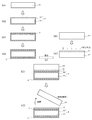
- FIG. 1 shows the cross-sectional structure of the composite substrate 1 according to the present embodiment.
- the composite substrate 1 shown in FIG. 1 has a structure in which a flattening layer 4 and a single crystal seed crystal layer 2 having a surface unevenness pattern and a thickness of 0.1 ⁇ m or more and 1.5 ⁇ m or less are laminated on a support substrate 3. I have. Further, if necessary, a stress adjusting layer 5 is provided on a surface (lower surface) opposite to the surface on which the flattening layer 4 of the support substrate 3 is laminated.
- the support substrate (base substrate) 3 includes a core 31 that is a core material of the support substrate 3 and a sealing layer 32 that covers the core 31.
- the material used for the core 31 is preferably nitride ceramics, which are excellent in heat resistance and stability and can be obtained in a large diameter size at low cost.
- nitride ceramics aluminum nitride (AlN), silicon nitride (Si 3 N 4), gallium nitride (GaN), or the like can be used boron nitride (BN) or mixtures thereof.
- AlN is particularly preferable because it is possible to produce a high-quality group III nitride crystal with little deformation because the lattice constant and the coefficient of thermal expansion are close to those of the target group III nitride crystal. Further, since AlN has high thermal conductivity, it is also preferable in that it is excellent in heat transfer in a post-process including heating.
- the shape and size of the core 31 is preferably a wafer shape with a thickness of 200 to 1000 ⁇ m because it can be placed on a normal semiconductor process line.
- AlN When AlN is used as the core 31, there are various methods for manufacturing AlN ceramics, but AlN powder is mixed with a sintering aid, an organic binder, a solvent, etc. to prepare a wafer-shaped green sheet, and after degreasing, an N 2 atmosphere. It is preferable to use the so-called sheet molding / atmospheric pressure sintering method, which is sintered and polished underneath, in that the productivity can be increased.
- the sintering aid but is selected from Y 2 O 3, Al 2 O 3, CaO or the like, particularly thermally conductive substrate after sintering is highly expressed to include Y 2 O 3 as a sintering aid Therefore, it is suitable.
- the sealing layer 32 is a layer that wraps and seals the entire core without gaps, and has a thickness of 0.05 ⁇ m or more and 1.5 ⁇ m or less. With such a structure, it is possible to prevent the substance caused by the ceramic material of the core 31 from leaking to the outside of the support substrate 3.
- the thickness of the sealing layer 32 is not preferable. On the other hand, a thickness of less than 0.05 ⁇ m is insufficient for the function of sealing the substance caused by the core 31. From the above, the thickness of the sealing layer 32 is preferably in the range of 0.05 ⁇ m or more and 1.5 ⁇ m or less. Since the effect of sealing the material material caused by the nitride ceramics is high, the material of the sealing layer 32 is preferably a film made of silicon nitride (Si 3 N 4).
- the sealing layer 32 is a dense film because the sealing performance is improved. Further, it is preferable that the sealing layer 32 is a high-purity film that does not contain impurities such as a sintering aid. By doing so, the sealing layer 32 is preferable because the leakage of unintended substances caused by itself to the outside of the support substrate 3 is suppressed.
- Such a high-purity film can be formed by using a film forming method such as a MOCVD method, a normal pressure CVD method, an LPCVD (low voltage CVD) method, or a sputtering method.
- a film forming method such as a MOCVD method, a normal pressure CVD method, an LPCVD (low voltage CVD) method, or a sputtering method.
- LPCVD low voltage CVD
- the thickness of the entire sealing layer 32 is preferably in the range of 0.05 ⁇ m or more and 1.5 ⁇ m or less.
- a flattening layer 3 having a thickness of 0.5 ⁇ m or more and 3.0 ⁇ m or less is laminated on the sealing layer 32.
- the flattening layer 4 By laminating the flattening layer 4, various voids and irregularities caused by the core 31 and the sealing layer 32 can be filled, and sufficient smoothness can be obtained for the seed crystal to be transferred.
- the thickness of the flattening layer 4 is preferably 0.5 to 3.0 ⁇ m.
- the thickness of the flattening layer 4 is less than 0.5 ⁇ m, the voids and irregularities generated in the support substrate 3 cannot be sufficiently filled, which is not preferable. Further, if the thickness of the flattening layer 4 is 3.0 ⁇ m or more, warpage is likely to occur, which is not preferable.
- a stress adjusting layer 5 is provided on the surface (lower surface) opposite to the upper surface on which the flattening layer 4 of the support substrate 3 is laminated.
- the stress adjusting layer 5 cancels out the stress generated by laminating the flattening layer 4 and reduces the warp.
- the flattening layer 4 may be laminated only on one side (upper surface) on the side where the seed crystal layer 2 of the support substrate 3 is laminated, but is formed so as to cover both sides (upper surface and lower surface) of the support substrate or the entire support substrate. It may be a film. In this way, the material laminated on the lower surface acts as the stress adjusting layer 5, and the stress caused by the flattening layer 4 is structurally canceled at the top and bottom of the substrate, so that the warp of the substrate is further reduced.
- the stress adjusting layer 5 a single piece of silicon (polycrystalline silicon or the like) may be laminated. By doing so, there is an advantage that the composite substrate can be attracted and detached by the electrostatic chuck.
- the material of the flattening layer 4 is silicon oxide (SiO 2 ), aluminum oxide (Al 2 O 3 ), silicon nitride (Si 3 N 4 ), silicon carbide (SiC) or silicon oxynitride (Si x O y N z ).
- Silicon (Si), gallium arsenide (GaAs), aluminum arsenide (AlAs) and the like may be selected.
- silicon oxide (SiO 2 ), silicon oxynitride (Si x Oy N z ), and aluminum arsenide (AlAs) are easy to grind and polish at the time of flattening, and are the target group III nitrides such as AlN. It is preferable because it tends to be a sacrificial layer for separating the support substrate 3 after epitaxially growing the material.
- the film formation of the flattening layer 4 can be arbitrarily selected from the plasma CVD method, the LPCVD method, the low pressure MOCVD method, or the like from the required film quality and the film formation efficiency. Depending on the condition of the laminated flattening layer 4, heat treatment for baking and CMP polishing are performed after the film formation to prepare for the formation of the seed crystal layer 2.
- a seed crystal layer 2 made of a single crystal of high quality Si ⁇ 111>, SiC, sapphire, aluminum nitride or gallium nitride is formed on the flattening layer 4 formed on the upper surface of the support substrate 3.
- the seed crystal layer 2 has an uneven pattern on the surface.
- the thickness of the seed crystal layer 2 is preferably 0.1 ⁇ m or more and 1.5 ⁇ m or less. By doing so, it becomes possible to form a high-quality seed crystal layer 2. That is, a high-quality crystal layer can be transferred to a thin film by applying ion implantation exfoliation to the above-mentioned single crystal substrate.
- the thickness of the seed crystal layer 2 is less than 0.1 ⁇ m, the damaged layer at the time of ion implantation is substantially close to the thickness, so that a good seed crystal cannot be obtained. Further, when the thickness of the seed crystal layer 2 becomes 1.5 ⁇ m or more, the ion implanter becomes enormous in size, which requires enormous investment and is not realistic.
- the high-quality single crystal used at this time is a general melting method (CZ method, FZ method), sublimation method, MOCVD method (metalorganic vapor phase growth method), HVPE (hydride vapor phase growth method) method.
- a single crystal obtained by any of the THVPE method (trihalide vapor phase growth method), or an epitaxially grown single crystal is preferable.
- the EPD of the single crystal is preferably a crystal having an extremely low dislocation density of 1 ⁇ 10 6 cm- 2 or less.
- the uneven pattern on the surface of the seed crystal layer 2 is formed by thin-film transfer of Si ⁇ 111>, SiC, sapphire, aluminum nitride or aluminum nitride gallium by ion implantation peeling, and then lithography is performed on the surface to obtain several ⁇ m to several tens of ⁇ m. It can be formed by forming a periodic groove or dot structure, or by forming an off-angle of 0.1 to 3 degrees by etching or the like. The pattern is appropriately selected according to the properties of the seed crystal substrate.
- the seed crystal layer 2 does not have to match the composition of the target epitaxially grown film, but it is preferably similar in crystal type and its lattice constant is as close to AlN as possible.
- the coefficient of thermal expansion is close to that of AlN, but since the seed crystal layer 2 is formed extremely thin by thin film transfer, the effect on warpage can be almost ignored as compared with the base substrate of the core. ..
- a thick seed crystal substrate that also serves as a base substrate and a seed crystal, if there is a difference in the coefficient of thermal expansion between the film to be epitaxially grown, the substrate warps significantly during film formation, and cracks and cracks occur. ..
- the seed crystal layer 2 in the case of aluminum nitride or aluminum gallium nitride, it is preferable that the resistivity of a 1 ⁇ 10 6 ⁇ ⁇ cm or more. By doing so, impurities incorporated into the target material epitaxially formed on the seed crystal layer 2 can be reduced, and coloring (that is, light absorption) of the target material can be suppressed.
- a core 31 made of nitride ceramics is prepared (S01 in FIG. 2).
- a sealing layer 32 having a thickness of 0.05 ⁇ m or more and 1.5 ⁇ m or less is formed so as to wrap the core 31 to form a support substrate 3 (S02 in FIG. 2).
- the sealing layer 32 may be formed into a film by the LPCVD method.
- a flattening layer 4 having a thickness of 0.5 ⁇ m or more and 3.0 ⁇ m or less is formed on the upper surface of the support substrate 3 (S03 in FIG. 2).
- the flattening layer 4 may be formed by any of a plasma CVD method, an LPCVD method, and a low-pressure MOCVD method.
- a stress adjusting layer 5 is further formed on the lower surface of the support substrate 3 (S04 in FIG. 2). The flattening layer 4 and the stress adjusting layer 5 may be formed at the same time.
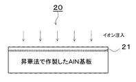
- a group III nitride single crystal substrate 20 for peeling and transferring the seed crystal layer 2 is prepared (S11 in FIG. 2).
- a specific method for preparing the single crystal substrate 20 will be described later.
- ion implantation is performed from one surface (ion implantation surface) of the single crystal substrate 20 to form a peeling position (embrittlement layer) 21 in the single crystal substrate 20 (S12 in FIG. 2). Ions implanted at this time, for example, H +, H 2 +, Ar +, or equal to He + and the like.
- the ion-implanted surface of the single crystal substrate 20 is bonded to the flattening layer 4 formed on the support substrate 3 to form a bonded substrate (S21 in FIG. 2).
- the single crystal substrate 20 is separated at the peeling position 21 of the single crystal substrate 20 in the bonded substrate (S22 in FIG. 2).
- a single crystal film of Si ⁇ 111>, SiC, sapphire, aluminum nitride, or aluminum gallium nitride is transferred as a seed crystal layer 2 on the flattening layer 4 on the support substrate 3.
- an uneven pattern is provided on the seed crystal layer 2.
- the support substrate 3, the flattening layer 4, and the seed crystal layer 2 provided with the uneven pattern are laminated to form a group III nitride-based composite substrate.
- the remaining portion of the separated group III nitride single crystal substrate 20 is used as a seed crystal for producing another group III nitride-based composite substrate by polishing the surface again to form an ion-implanted surface. It can be repeatedly used to transfer the layer to a thin film.
- the ion injection surface of the single crystal substrate 20 is once bonded to another temporary support substrate such as a silicon wafer, separated and the seed crystal layer 2 is bonded to the temporary support substrate, and the seed crystal layer 2 is bonded to the temporary support substrate.
- a step of separating the temporary support substrate from the seed crystal layer may be performed. By doing so, the seed crystal layer 2 bonded to the flattening layer 4 can be turned upside down.
- the single crystal substrate 20 a commercially available substrate can be used as it is for Si ⁇ 111>, SiC, or a sapphire substrate, which is easy to obtain as a commercially available substrate with a large diameter.
- a commercially available substrate can be used as it is for Si ⁇ 111>, SiC, or a sapphire substrate, which is easy to obtain as a commercially available substrate with a large diameter.
- aluminum nitride or aluminum gallium nitride which is difficult to obtain for a large-diameter substrate
- aluminum nitride or nitride is used on a large-diameter sapphire substrate by either the MOCVD method, the HVPE method, or the THVPE method (trihalide vapor phase growth method).
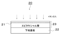
- FIG. 3 is a diagram showing a layer structure of a single crystal substrate 20 in the case of ion-implanting a plurality of small-diameter sublimation substrates into a laminated large-diameter substrate in the same direction.
- the laminated substrate of the substrate is used as the base substrate 22, and an epitaxial film is formed on the substrate by any of the MOCVD method, the HVPE method, and the THVPE method, and the single crystal epitaxial layer substrate is used.
- the seed crystal layer 2 can be formed without consuming the expensive AlN substrate produced by the sublimation method, and the manufacturing cost can be reduced.
- the AlN substrate produced by the sublimation method is generally small in diameter, expensive and easy to color, but has excellent crystal characteristics. As shown in FIG. 3, a plurality of small-diameter single crystals are bonded together to prepare a large-diameter substrate, and then ion implantation is performed to perform thin film transfer to a thickness of 0.1 ⁇ m to 1.5 ⁇ m, and the remaining single crystal substrate remains. If the remainder of the above is reused for the production of the next composite substrate and used repeatedly, the cost for manufacturing the composite substrate can be reduced and the seed crystal functions as an extremely good seed crystal.
- the sublimation substrate is not used as a thick substrate of several hundred ⁇ m as in the past, but is used as an ultra-thin thin film of 0.1 ⁇ m to 1.5 ⁇ m in thin film transfer, so it is similar to the original substrate. Coloring does not matter.
- the thin film transfer is performed with a thickness of 0.1 ⁇ m to 1.5 ⁇ m, and the remaining portion of the remaining single crystal epitaxial layer substrate is reused for the production of the next composite substrate. You should use it.
- the single crystal epitaxial layer substrate can be used repeatedly, the cost for manufacturing the composite substrate can be significantly reduced.
- the epitaxial layer is epitaxially formed by any of the MOCVD method, the HVPE method, and the THVPE method, using the remaining portion of the single crystal epitaxial layer substrate whose epitaxial layer portion has become thin as the base substrate. By regenerating the layer, the first substrate can be used repeatedly, and the production cost can be further reduced.
- Example 1 (Preparation of support board) (1) AlN powder, the Y 2 O 3, 5 parts by weight to 100 parts by weight of the sintering aid, by mixing an organic binder, a solvent such as, after producing a green sheet, degreased, N 2 under, 1900 ° C. A double-sided polished ⁇ (diameter) 8 inch ⁇ t (thickness) 725 ⁇ m AlN substrate (AlN polycrystalline ceramic substrate) was used as a core.
- the damaged portion of the seed crystal layer damaged by the Si single crystal during ion implantation and transfer was lightly polished with CMP to make the thickness of the seed crystal layer 0.5 ⁇ m.
- a pattern of periodic irregularities having a groove depth of 0.3 ⁇ m, a groove width of 3 ⁇ m, and a terrace width of 5 ⁇ m was formed on the Si seed crystal layer.
- the rest of the Si single crystal substrate after thin film transfer (that is, the portion peeled off and separated without being transferred to the support substrate) can be used as a large number of seed crystals by repeatedly performing ion implantation, and is extremely. It was economical.
- ⁇ 8 having a support substrate having a structure of (1) an AlN ceramic core and (2) a sealing layer, a flattening layer having a thickness of 3 ⁇ m and a Si ⁇ 111> seed crystal layer having a thickness of 0.5 ⁇ m.
- An inch III nitride based epitaxial growth substrate was obtained.
- the above substrate was further evaluated as the following simple AlN epitaxial growth substrate. That is, 2 ⁇ m of AlN is formed on the AlN epitaxial substrate by the MOCVD method, and etch pits are generated by a molten alkali (KOH + NaOH) etching method in order to evaluate the dislocation density (Etch pit Density, hereinafter referred to as EPD).
- EPD Etch pit Density
- XRC X-ray locking curve
- the full width at half maximum FWHM in the XRC measurement of the (0002) plane of the substrate was 321 arcsec, and a high quality AlN single crystal was obtained. From these results, it can be seen that the epitaxial substrate according to this embodiment is excellent.
- the above substrate was further evaluated as the following simple AlN epitaxial growth substrate. That is, 2 ⁇ m of AlN was formed on the AlN epitaxial substrate by the MOCVD method, and etch pits were generated by the molten alkali (KOH + NaOH) etching method in order to evaluate the dislocation density, and EPD was measured.
- XRC measurement was performed as an evaluation of crystallinity. As a result, EPD showed an extremely low dislocation density of 3 ⁇ 10 6 cm- 2.
- the half-value width FWHM in the XRC measurement of the (0002) plane of the substrate was 731 arcsec, and both the dislocation density and the half-value width were inferior to those of Example 1.
- Example 2 (Preparation of support board)
- the core was an AlN polycrystalline ceramic substrate similar to that in Example 1.
- (2) First as the sealing layer covers the entire AlN ceramic core as encompassing at SiO 2 layer 0.5 ⁇ m thick by LPCVD method, in another LPCVD apparatus further thereon, a 0.8 ⁇ m thick Si 3 N The whole was sealed with four layers (total thickness of the sealing layer 1.3 ⁇ m) to prepare a support substrate.
- the AlN crystal used as a seed crystal was prepared by a sublimation method (improved release method) according to the following procedure.
- a TaC crucible was further placed in a growth container made of graphite that had been subjected to a high purification treatment, and a high-purity AlN raw material was provided at the bottom of the TaC crucible and AlN crystals were provided at the top.
- the growth vessel and crucible were heated by high-frequency induction heating, the raw material portion was kept at 2000 ° C., the raw material was sublimated and decomposed, and an AlN single crystal was precipitated on the upper AlN crystal.
- This AlN single crystal was sliced and polished to make a smooth ⁇ 2-inch substrate with a thickness of 200 ⁇ m.
- the resistivity was measured at 8 points in the plane of this substrate at equal intervals, it was 1 ⁇ 10 6 ⁇ ⁇ cm to 3 ⁇ 10 11 ⁇ ⁇ cm.
- the light transmittance at a wavelength of 230 nm was 0.2% in terms of thickness of 100 ⁇ m.
- the 2-inch substrate produced above was used as a regular hexagonal AlN substrate, and a plurality of the substrates were used, aligned with each other, and bonded to a ⁇ 8-inch quartz substrate. After that, the outer circumference of the quartz substrate was trimmed by cutting an excess portion so as to become a ⁇ 8 inch substrate. Ion implantation of hydrogen at a depth of 0.6 ⁇ m (peeling position) and a dose amount of 8 ⁇ 10 17 cm- 2 was carried out at 100 keV on the ⁇ 8 inch AlN single crystal substrate thus prepared. The ion-implanted surface of the AlN single crystal substrate after the ion implantation was bonded to the flattening layer of the support substrate prepared in advance.
- the seed crystal layer of the AlN single crystal was thin-film transferred to the support substrate by peeling and separating at the peeling position (0.6 ⁇ m portion).
- the damaged portion of the seed crystal layer damaged by the AlN single crystal during ion implantation and transfer was lightly polished with CMP to make the thickness of the AlN seed crystal layer 0.4 ⁇ m.
- a ⁇ 8 inch ⁇ 8 inch support substrate having a structure of (1) an AlN ceramic core and (2) a sealing layer is provided with a 2 ⁇ m-thick flattening layer and a 0.4 ⁇ m-thick AlN seed crystal layer.
- a group III nitride-based epitaxial growth substrate was obtained.
- the group III nitride-based epitaxial growth substrate obtained in this example was evaluated as a simple AlN epitaxial growth substrate in the same manner as in Example 1. That is, 2 ⁇ m of AlN was formed on the AlN epitaxial substrate by the MOCVD method, and EPD was measured by the molten alkali (KOH + NaOH) etching method in order to evaluate the dislocation density. In addition, XRC measurement was performed as an evaluation of crystallinity. As a result, EPD showed an extremely low dislocation density of 2.3 ⁇ 10 4 cm -2.
- the full width at half maximum FWHM in the XRC measurement of the (0002) plane of the substrate was 132 arcsec, and a high quality AlN single crystal was obtained. From these results, it can be seen that the epitaxial substrate according to this embodiment is excellent.
- Example 2 After transferring the AlN crystal to a thin film in Example 2, the conditions were the same except that the thin film was used as it was as a seed crystal layer without forming an off-angle at all.
- This epitaxial substrate was evaluated by forming a 2 ⁇ m AlN film by the MOCVD method in the same manner as in Example 2. As a result, the EPD was 6.5 ⁇ 10 6 cm- 2 . Further, the FWHM in the XRC measurement of the (0002) plane of the substrate was 1950 arcsec, and the quality of the crystal was considerably inferior to that of Example 2.
- Example 2 In order to increase the size of the seed substrate, a plurality of AlN substrates were used and bonded in the same direction, but it is considered that a slight difference in crystal orientation and the like adversely affected the crystal growth. On the contrary, in Example 2, it is considered that by positively providing the uneven pattern on the surface of the seed crystal layer, adverse effects on crystal growth such as these crystal defects and slight misalignment of orientation are absorbed. Will be.
- the substrate obtained from this comparative example had poor crystallinity and was unsuitable as an epitaxial substrate for growing a group III nitride single crystal for deep ultraviolet rays.
- Example 3 The conditions were the same except that the flattening layer was changed from SiO 2 having a thickness of 3 ⁇ m to Al As having a thickness of 2 ⁇ m in Example 1.
- a support substrate having a structure of (1) an AlN ceramic core and (2) a sealing layer was provided with a 2 ⁇ m-thick AlAs flattening layer and a 0.5 ⁇ m-thick Si ⁇ 111> seed crystal layer.
- a group III nitride-based epitaxial growth substrate was obtained.
- AlN was further laminated by the HVPE method on the group III nitride-based epitaxial growth substrate by 50 mm.
- This laminate was immersed in a 25% HCl aqueous solution to dissolve the AlAs layer, and 50 mm AlN crystals were separated from the support substrate.
- This AlN crystal was subjected to cylindrical grinding, slicing, and polishing to obtain 50 solid ⁇ 8 inch AlN single crystal substrates.
- Example 2 the same simple evaluation as in Example 1 was performed using the substrate as an AlN epitaxial substrate.
- EPD showed an extremely low dislocation density of 5.0 ⁇ 10 4 cm -2.
- the FWHM measured by XRC on the (0002) plane of the substrate was 132 arcsec, and a high quality AlN single crystal was obtained. No coloring was observed in this product, and the light transmittance at a wavelength of 230 nm was as good as about 90%, which was suitable as a device substrate in the deep ultraviolet region.
Landscapes
- Chemical & Material Sciences (AREA)
- Engineering & Computer Science (AREA)
- Materials Engineering (AREA)
- Organic Chemistry (AREA)
- Metallurgy (AREA)
- Crystallography & Structural Chemistry (AREA)
- Physics & Mathematics (AREA)
- Manufacturing & Machinery (AREA)
- Computer Hardware Design (AREA)
- Power Engineering (AREA)
- Microelectronics & Electronic Packaging (AREA)
- General Physics & Mathematics (AREA)
- Condensed Matter Physics & Semiconductors (AREA)
- Inorganic Chemistry (AREA)
- General Chemical & Material Sciences (AREA)
- Chemical Kinetics & Catalysis (AREA)
- Mechanical Engineering (AREA)
- Ceramic Engineering (AREA)
- Electromagnetism (AREA)
- Crystals, And After-Treatments Of Crystals (AREA)
- Recrystallisation Techniques (AREA)
- Structural Engineering (AREA)
Priority Applications (4)
| Application Number | Priority Date | Filing Date | Title |
|---|---|---|---|
| US18/012,033 US20230257905A1 (en) | 2020-07-01 | 2021-05-18 | Large-diameter substrate for group-iii nitride epitaxial growth and method for producing the same |
| CN202180046066.2A CN115997050A (zh) | 2020-07-01 | 2021-05-18 | 大口径iii族氮化物系外延生长用基板及其制造方法 |
| KR1020227044577A KR20230031835A (ko) | 2020-07-01 | 2021-05-18 | 대구경 iii족 질화물계 에피택셜 성장용 기판과 그 제조 방법 |
| EP21831686.7A EP4177384A1 (en) | 2020-07-01 | 2021-05-18 | Large-diameter substrate for group-iii nitride epitaxial growth and method for producing the same |
Applications Claiming Priority (2)
| Application Number | Priority Date | Filing Date | Title |
|---|---|---|---|
| JP2020114475A JP2022012558A (ja) | 2020-07-01 | 2020-07-01 | 大口径iii族窒化物系エピタキシャル成長用基板とその製造方法 |
| JP2020-114475 | 2020-07-01 |
Publications (1)
| Publication Number | Publication Date |
|---|---|
| WO2022004165A1 true WO2022004165A1 (ja) | 2022-01-06 |
Family
ID=79315945
Family Applications (1)
| Application Number | Title | Priority Date | Filing Date |
|---|---|---|---|
| PCT/JP2021/018734 WO2022004165A1 (ja) | 2020-07-01 | 2021-05-18 | 大口径iii族窒化物系エピタキシャル成長用基板とその製造方法 |
Country Status (7)
| Country | Link |
|---|---|
| US (1) | US20230257905A1 (ko) |
| EP (1) | EP4177384A1 (ko) |
| JP (1) | JP2022012558A (ko) |
| KR (1) | KR20230031835A (ko) |
| CN (1) | CN115997050A (ko) |
| TW (1) | TW202219340A (ko) |
| WO (1) | WO2022004165A1 (ko) |
Cited By (1)
| Publication number | Priority date | Publication date | Assignee | Title |
|---|---|---|---|---|
| WO2023127249A1 (ja) * | 2021-12-28 | 2023-07-06 | 信越化学工業株式会社 | 高特性エピタキシャル成長用基板とその製造方法 |
Families Citing this family (2)
| Publication number | Priority date | Publication date | Assignee | Title |
|---|---|---|---|---|
| JP7484773B2 (ja) | 2021-03-04 | 2024-05-16 | 信越半導体株式会社 | 紫外線発光素子用エピタキシャルウェーハの製造方法、紫外線発光素子用基板の製造方法及び紫外線発光素子用エピタキシャルウェーハ |
| CN117476831B (zh) * | 2023-12-20 | 2024-03-19 | 青禾晶元(晋城)半导体材料有限公司 | Led外延片及其制备方法、led芯片及其制备方法 |
Citations (6)
| Publication number | Priority date | Publication date | Assignee | Title |
|---|---|---|---|---|
| JPH0326607B2 (ko) | 1984-02-06 | 1991-04-11 | Tokyo Shibaura Electric Co | |
| JP2004336079A (ja) * | 2004-08-16 | 2004-11-25 | Hoya Corp | 化合物単結晶の製造方法 |
| JP4565042B1 (ja) | 2009-04-22 | 2010-10-20 | 株式会社トクヤマ | Iii族窒化物結晶基板の製造方法 |
| US20140070166A1 (en) * | 2009-09-10 | 2014-03-13 | Micron Technology, Inc. | Epitaxial formation structures and associated methods of manufacturing solid state lighting devices |
| JP2017114694A (ja) * | 2015-12-21 | 2017-06-29 | 信越化学工業株式会社 | 化合物半導体積層基板及びその製造方法、並びに半導体素子 |
| US20180005827A1 (en) * | 2016-06-13 | 2018-01-04 | Quora Technology, Inc. | Multi-deposition process for high quality gallium nitride device manufacturing |
Family Cites Families (1)
| Publication number | Priority date | Publication date | Assignee | Title |
|---|---|---|---|---|
| CN109844184B (zh) | 2016-06-14 | 2021-11-30 | 克罗米斯有限公司 | 用于功率应用和射频应用的工程化衬底结构 |
-
2020
- 2020-07-01 JP JP2020114475A patent/JP2022012558A/ja active Pending
-
2021
- 2021-05-18 CN CN202180046066.2A patent/CN115997050A/zh active Pending
- 2021-05-18 KR KR1020227044577A patent/KR20230031835A/ko unknown
- 2021-05-18 US US18/012,033 patent/US20230257905A1/en active Pending
- 2021-05-18 WO PCT/JP2021/018734 patent/WO2022004165A1/ja unknown
- 2021-05-18 EP EP21831686.7A patent/EP4177384A1/en active Pending
- 2021-06-29 TW TW110123734A patent/TW202219340A/zh unknown
Patent Citations (6)
| Publication number | Priority date | Publication date | Assignee | Title |
|---|---|---|---|---|
| JPH0326607B2 (ko) | 1984-02-06 | 1991-04-11 | Tokyo Shibaura Electric Co | |
| JP2004336079A (ja) * | 2004-08-16 | 2004-11-25 | Hoya Corp | 化合物単結晶の製造方法 |
| JP4565042B1 (ja) | 2009-04-22 | 2010-10-20 | 株式会社トクヤマ | Iii族窒化物結晶基板の製造方法 |
| US20140070166A1 (en) * | 2009-09-10 | 2014-03-13 | Micron Technology, Inc. | Epitaxial formation structures and associated methods of manufacturing solid state lighting devices |
| JP2017114694A (ja) * | 2015-12-21 | 2017-06-29 | 信越化学工業株式会社 | 化合物半導体積層基板及びその製造方法、並びに半導体素子 |
| US20180005827A1 (en) * | 2016-06-13 | 2018-01-04 | Quora Technology, Inc. | Multi-deposition process for high quality gallium nitride device manufacturing |
Non-Patent Citations (4)
| Title |
|---|
| FUJIKURA TECHNICAL REVIEW, vol. 2, no. 119, 2010, pages 33 - 38 |
| JOURNAL OF CRYSTAL GROWTH, vol. 411, 2015, pages 38 - 44 |
| LEDS MAGAZINE JAPAN, December 2016 (2016-12-01), pages 30 - 31 |
| SEI TECHNICAL REVIEW, vol. 177, pages 88 - 91 |
Cited By (1)
| Publication number | Priority date | Publication date | Assignee | Title |
|---|---|---|---|---|
| WO2023127249A1 (ja) * | 2021-12-28 | 2023-07-06 | 信越化学工業株式会社 | 高特性エピタキシャル成長用基板とその製造方法 |
Also Published As
| Publication number | Publication date |
|---|---|
| US20230257905A1 (en) | 2023-08-17 |
| JP2022012558A (ja) | 2022-01-17 |
| CN115997050A (zh) | 2023-04-21 |
| EP4177384A1 (en) | 2023-05-10 |
| TW202219340A (zh) | 2022-05-16 |
| KR20230031835A (ko) | 2023-03-07 |
Similar Documents
| Publication | Publication Date | Title |
|---|---|---|
| WO2022004165A1 (ja) | 大口径iii族窒化物系エピタキシャル成長用基板とその製造方法 | |
| JP2021195299A (ja) | Iii族窒化物系エピタキシャル成長用基板とその製造方法 | |
| US20240141552A1 (en) | Seed substrate for epitaxial growth use and method for manufacturing same, and semiconductor substrate and method for manufacturing same | |
| WO2021140793A1 (ja) | Iii族窒化物基板の製造方法及びiii族窒化物基板 | |
| WO2021250991A1 (ja) | Iii族窒化物系エピタキシャル成長用基板とその製造方法 | |
| WO2023127249A1 (ja) | 高特性エピタキシャル成長用基板とその製造方法 | |
| WO2023233781A1 (ja) | Iii族窒化物単結晶基板の製造方法 | |
| WO2024084836A1 (ja) | 窒化物半導体エピタキシャルウエーハの製造方法及び窒化物半導体エピタキシャルウエーハ用複合基板 | |
| WO2023074045A1 (ja) | エピタキシャル成長用種基板およびその製造方法、ならびに半導体基板およびその製造方法 | |
| JP7204625B2 (ja) | Iii族化合物基板の製造方法及びその製造方法により製造した基板 | |
| WO2023176185A1 (ja) | 高特性エピ用種基板、高特性エピ用種基板の製造方法、半導体基板、および半導体基板の製造方法 | |
| WO2024057698A1 (ja) | 窒化物半導体層付き単結晶シリコン基板及び窒化物半導体層付き単結晶シリコン基板の製造方法 | |
| CN116940720A (zh) | 外延生长用种子基板及其制造方法、和半导体基板及其制造方法 | |
| WO2021014834A1 (ja) | Iii族化合物基板の製造方法及びその製造方法により製造した基板 | |
| CN118159693A (zh) | 外延生长用种子基板及其制造方法和半导体基板及其制造方法 | |
| TW202331794A (zh) | 氮化物半導體基板及氮化物半導體基板的製造方法 |
Legal Events
| Date | Code | Title | Description |
|---|---|---|---|
| 121 | Ep: the epo has been informed by wipo that ep was designated in this application |
Ref document number: 21831686 Country of ref document: EP Kind code of ref document: A1 |
|
| NENP | Non-entry into the national phase |
Ref country code: DE |
|
| ENP | Entry into the national phase |
Ref document number: 2021831686 Country of ref document: EP Effective date: 20230201 |