WO2022003979A1 - エレベーターの昇降体の変位抑制装置 - Google Patents
エレベーターの昇降体の変位抑制装置 Download PDFInfo
- Publication number
- WO2022003979A1 WO2022003979A1 PCT/JP2020/026272 JP2020026272W WO2022003979A1 WO 2022003979 A1 WO2022003979 A1 WO 2022003979A1 JP 2020026272 W JP2020026272 W JP 2020026272W WO 2022003979 A1 WO2022003979 A1 WO 2022003979A1
- Authority
- WO
- WIPO (PCT)
- Prior art keywords
- stopper
- guide rail
- elevator
- car
- drive unit
- Prior art date
- Legal status (The legal status is an assumption and is not a legal conclusion. Google has not performed a legal analysis and makes no representation as to the accuracy of the status listed.)
- Ceased
Links
Images







Classifications
-
- B—PERFORMING OPERATIONS; TRANSPORTING
- B66—HOISTING; LIFTING; HAULING
- B66B—ELEVATORS; ESCALATORS OR MOVING WALKWAYS
- B66B11/00—Main component parts of lifts in, or associated with, buildings or other structures
- B66B11/02—Cages, i.e. cars
-
- B—PERFORMING OPERATIONS; TRANSPORTING
- B66—HOISTING; LIFTING; HAULING
- B66B—ELEVATORS; ESCALATORS OR MOVING WALKWAYS
- B66B7/00—Other common features of elevators
- B66B7/02—Guideways; Guides
Definitions
- This disclosure relates to a displacement suppressing device for an elevator elevator.
- Patent Document 1 discloses an example of an elevator.
- a seismic plate is installed in the car.
- the seismic plate works with the guide rails to reduce lateral displacement of the car.
- the guide rail may bend due to the reaction force received from the elevating body such as a car.
- the present disclosure provides a displacement suppressing device for an elevator elevator whose guide rail is less likely to bend due to a reaction force received from the elevator.
- the displacement suppressing device for an elevator elevating body includes a stopper unit provided on the elevator elevating body that travels along a guide rail having a plurality of restraining portions and stops at one of a plurality of stop positions in normal operation.
- the stopper unit includes a stopper facing the guide rail, a first drive unit that moves the relative position of the stopper with respect to the elevating body in the traveling direction of the elevating body, and makes the stopper face any of a plurality of restraining parts, and a stopper.
- a second drive unit is provided, which changes the gap between the guide rail and the stopper by moving the guide rail and suppresses the displacement of the elevating body by a stopper that narrows the gap between the guide rail and the stopper.
- the guide rail is less likely to bend due to the reaction force received from the elevating body.
- FIG. It is a block diagram of the elevator which concerns on Embodiment 1.
- FIG. It is a front view of the car which concerns on Embodiment 1.
- FIG. It is a top view of the stopper unit which concerns on Embodiment 1.
- FIG. It is a side view of the stopper unit which concerns on Embodiment 1.
- FIG. It is a block diagram of the stopper unit which concerns on Embodiment 1.
- FIG. It is a block diagram of the stopper unit which concerns on Embodiment 1.
- FIG. It is a top view of the stopper unit which concerns on Embodiment 1.
- FIG. It is a flow chart which shows the example of the operation of the elevator which concerns on Embodiment 1.
- FIG. It is a front view of the car which concerns on Embodiment 1.
- FIG. It is a top view of the stopper unit which concerns on Embodiment 1.
- FIG. It is a side view of the stopper unit which concerns on Embodiment 1.
- FIG.
- FIG. It is a figure which shows the example of the operation timing of the elevator which concerns on Embodiment 1.
- FIG. It is a figure which shows the example of the operation timing of the elevator which concerns on Embodiment 1.
- FIG. It is a top view of the stopper unit which concerns on Embodiment 1.
- FIG. It is a top view of the stopper unit which concerns on Embodiment 1.
- FIG. It is a figure which shows the example of the operation timing of the elevator 1 which concerns on the modification of Embodiment 1.
- FIG. It is a hardware block diagram of the main part of the displacement suppression apparatus which concerns on Embodiment 1.
- FIG. It is a flow chart which shows the example of the operation of the elevator which concerns on Embodiment 2.
- FIG. 1 It is a figure which shows the example of the operation timing of the elevator which concerns on Embodiment 2.
- FIG. It is a figure which shows the example of the operation timing of the elevator which concerns on Embodiment 3.
- FIG. It is a top view of the stopper unit which concerns on Embodiment 4.
- FIG. It is a top view of the stopper unit which concerns on Embodiment 4.
- FIG. 1 is a configuration diagram of an elevator 1 according to the first embodiment.
- the elevator 1 is installed in a building 2 having a plurality of floors.
- a hoistway 3 is provided in the building 2.
- the hoistway 3 is a space that spans a plurality of floors.
- the machine room 4 is provided above the hoistway 3.
- a pit 5 is provided at the bottom of the hoistway 3.
- Elevator 1 includes a hoist 6, a main rope 7, a basket 8, and a counterweight 9.
- the hoisting machine 6 includes a sheave and a motor.
- the motor of the hoisting machine 6 is a device for rotating and driving the sheave of the hoisting machine 6.
- the hoisting machine 6 is provided in, for example, the machine room 4.
- the main rope 7 is wound around the sheave of the hoist 6. One end of the main rope 7 is connected to the car 8. The other end of the main rope 7 is connected to the counterweight 9.
- the elevator 1 may include a plurality of main ropes 7.
- the car 8 is a device for transporting a user or the like between a plurality of floors by traveling in the vertical direction on the hoistway 3.
- the counterweight 9 is a device that balances the load applied to both sides of the sheave of the hoist 6 through the main rope 7 with the car 8.
- the car 8 and the counterweight 9 are suspended in the hoistway 3 by the main rope 7.
- the car 8 and the counterweight 9 travel on the hoistway 3 in opposite directions by the hoisting machine 6 winding up the main rope 7.
- Each of the cage 8 and the counterweight 9 is an example of an elevating body.
- a pair of car guide rails 10, a pair of counterweight guide rails 11, and a plurality of brackets 12 are provided.
- the pair of car guide rails 10 is a pair of guide rails that guide the traveling of the car 8 on the hoistway 3. Each car guide rail 10 is arranged along the vertical direction in the hoistway 3. One car guide rail 10 is arranged on the left side of the car 8. The other car guide rail 10 is arranged on the right side of the car 8.
- the pair of counterweight guide rails 11 is a pair of guide rails that guide the traveling of the counterweight 9 on the hoistway 3. Each counterweight guide rail 11 is arranged along the vertical direction in the hoistway 3. One of the counterweight guide rails 11 is arranged on the left side of the counterweight 9. The other counterbalance weight guide rail 11 is arranged on the right side of the counterbalance weight 9.
- the elevating body such as the car 8 or the counterweight 9 travels in the vertical direction along the guide rail such as the car guide rail 10 or the counterweight guide rail 11.
- Each of the guide rails that guide the traveling of the elevating body is fixed to the hoistway 3 by the plurality of brackets 12.
- Each guide rail has a plurality of restraint portions 13.
- Each restraint portion 13 is a portion where the horizontal displacement of the guide rail is constrained.
- the restraint portion 13 is, for example, a portion fixed by the bracket 12 on the guide rail.
- the distance between the brackets 12 in the vertical direction in the hoistway 3 is shorter than, for example, the height of the car 8.
- each bracket 12 may be arranged corresponding to any of the stop positions of the elevating body.
- Elevator 1 includes an earthquake detector 14 and a control panel 15.
- the earthquake detector 14 is a part that detects the occurrence of an earthquake.
- the seismic detector 14 is provided, for example, in the pit 5.
- the seismic detector 14 is a P wave detector that detects an earthquake by, for example, a P wave (Primary wave).
- the seismic detector 14 is provided, for example, in the machine room 4.
- the earthquake detector 14 is an S wave detector that detects an earthquake by, for example, an S wave (Secondary wave).
- the seismic detector 14 may be provided in both the pit 5 and the machine room 4.
- the control panel 15 is a device that controls the operation of the elevator 1.
- the control panel 15 is provided in, for example, the machine room 4.
- the control panel 15 controls the traveling of the car 8 and the counterweight 9 by, for example, controlling the operation of the hoisting machine 6.
- the control panel 15 manages the operation mode of the elevator 1.
- the operation mode of the elevator 1 includes normal operation and seismic control operation.
- the normal operation is an operation mode in which the car 8 is driven so as to answer a call or the like registered by the user. In normal operation, the car 8 stops at one of a plurality of floors. The position of each floor is an example of the stop position in normal operation for the car 8. Further, when the car 8 stops on any floor, the counterweight 9 stops at a position corresponding to the floor.
- the position where the counterweight 9 stops corresponding to each floor is an example of the stop position in the normal operation of the counterweight 9.
- the earthquake control operation is an operation mode when the occurrence of an earthquake is detected in the elevator 1 by, for example, an earthquake detector 14.
- the control panel 15 stops, for example, the traveling car 8 on the nearest floor.
- the detection of the occurrence of an earthquake in the elevator 1 may be performed based on information such as an earthquake occurrence forecast or warning provided from the outside of the elevator 1 such as an Earthquake Early Warning.
- the detection of the occurrence of an earthquake in the elevator 1 may be performed, for example, by receiving a signal for seismic detection by an earthquake detector provided in a building closer to the epicenter than the building 2.
- FIG. 2 is a front view of the car 8 according to the first embodiment.
- the car 8 includes a car frame 16, a plurality of guide shoes 17, and a displacement suppressing device 18.
- the car frame 16 includes an upper beam 19, a lower beam 20, and a pair of vertical columns 21.
- the upper beam 19 is a member arranged between the left end portion and the right end portion in the upper part of the car 8.
- the lower beam 20 is a member arranged between the left end portion and the right end portion in the lower part of the car 8.
- the pair of vertical columns 21 are members arranged between the upper beam 19 and the lower beam 20.
- One vertical pillar 21 is arranged at the left end of the car 8.
- the other vertical pillar 21 is arranged at the right end of the car 8.
- the left vertical pillar 21 is arranged along the left car guide rail 10 of the car 8.
- the vertical pillar 21 on the right side is arranged along the car guide rail 10 on the right side of the car 8.
- the plurality of guide shoes 17 are portions guided by a pair of car guide rails 10. Each guide shoe 17 faces one of the car guide rails 10. Each guide shoe 17 is attached to, for example, a car frame 16. Each guide shoe 17 is arranged, for example, at the left end portion or the right end portion of the upper beam 19 or the lower beam 20.
- the displacement suppressing device 18 is a device that suppresses the horizontal displacement of an elevating body such as a car 8.
- the displacement suppressing device 18 includes a plurality of stopper units 22 and a control unit 23.
- Each stopper unit 22 is a portion that regulates the displacement of the car 8 by the car guide rail 10.
- Each stopper unit 22 is attached to, for example, the upper part or the lower part of any of the vertical columns 21.
- the control unit 23 is a part that controls the operation of each stopper unit 22.
- the control unit 23 is mounted on, for example, the control panel 15 of the elevator 1.
- the control unit 23 may be provided, for example, on the upper part of the car 8.
- the displacement suppressing device 18 may be provided with individual control units 23 corresponding to one-to-one in each stopper unit 22.
- the control unit 23 includes a storage unit 24 and a command unit 25.
- the storage unit 24 is a portion that stores information. In the storage unit 24, for example, the positions of the plurality of restraint units 13 on the car guide rail 10 are stored.
- the command unit 25 is a unit that outputs a command signal to each stopper unit 22 based on the input information, the information stored in the storage unit 24, and the like.
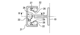
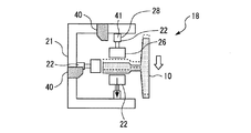
- FIG. 3 is a top view of the stopper unit 22 according to the first embodiment.
- FIG. 3 shows a cross-sectional view taken along the line AA in FIG.
- stopper units 22 are attached to the upper part of each vertical pillar 21. Further, three stopper units 22 are similarly provided at the lower part of each vertical pillar 21. In FIG. 3, the upper three stopper units 22 are shown. Each stopper unit 22 operates independently of each other.
- Each stopper unit 22 includes a stopper 26.
- the stopper 26 is a member facing the surface of the car guide rail 10. In one of the three stopper units 22, the stopper 26 faces the front surface of the car guide rail 10. In the other one of the three stopper units 22, the stopper 26 faces the rear surface of the car guide rail 10. In the remaining one of the three stopper units 22, the stopper 26 faces the left and right inner side surfaces of the car guide rail 10. Here, the left and right inner side surfaces are the side surfaces on the car 8 side.
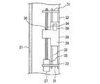
- FIG. 4 is a side view of the stopper unit 22 according to the first embodiment.
- FIG. 4 shows a sectional view taken along the line BB in FIG.
- Each stopper unit 22 includes a first drive unit 27 and a second drive unit 28.
- the first drive unit 27 is a portion that moves the relative position of the stopper 26 with respect to the car 8 in the vertical direction.
- the second drive unit 28 is a portion that changes the gap between the car guide rail 10 and the stopper 26 by moving the stopper 26.
- the second drive unit 28 includes a frame 29.
- the frame 29 is a portion that holds the stopper 26.
- a screw hole 30 is provided in the vertical direction.
- the first drive unit 27 includes a pair of bearings 31, a guide shaft 32, a drive motor 33, and a ball screw 34.
- the pair of bearings 31 are arranged above and below the range of movement of the relative position of the stopper 26 by the first drive unit 27.
- the guide shaft 32 is arranged parallel to the vertical column 21 between the pair of bearings 31.
- the first drive unit 27 may include a plurality of guide shafts 32 parallel to each other.
- the drive motor 33 is attached to one of the bearings 31.
- the ball screw 34 is arranged parallel to the guide shaft 32 between the other bearing 31 and the drive motor 33.
- the ball screw 34 is passed through the screw hole 30 of the frame 29 of the second drive unit 28.
- the first drive unit 27 rotates the ball screw 34 by the drive motor 33 based on the control of the control unit 23, so that the stopper 26 is moved in the vertical direction together with the second drive unit 28.
- the first drive unit 27 may move the relative position of the stopper 26 in the vertical direction by another method.
- the first drive unit 27 may have a linear motor for moving the frame 29 or the like in the vertical direction, a hydraulic or pneumatic cylinder, or the like.
- FIG. 5 is a configuration diagram of the stopper unit 22 according to the first embodiment.
- FIG. 5 shows a side view of the internal structure of the second drive unit 28.
- the stopper 26 faces the surface of the car guide rail 10 with a vertical surface parallel to the surface of the car guide rail 10.
- the stopper 26 has a vertical surface and a first slope 35 on the opposite side of the car guide rail 10.
- the first slope 35 is a surface that is inclined with respect to the surface of the car guide rail 10.
- the first slope 35 is, for example, a surface inclined downward.
- the first slope 35 is provided below the vertical surface on the opposite side of the car guide rail 10.
- the stopper 26 is movably held so that the gap between the stopper 26 and the car guide rail 10 can be changed by the guidance of the frame 29.
- the stopper 26 is guided to move downward when it leaves the car guide rail 10.
- FIG. 5 shows a state in which the gap between the stopper 26 and the car guide rail 10 is widened.
- the second drive unit 28 includes a moving piece 36, a push-up spring 37, and an actuator 38.
- the moving piece 36 is a portion that is movably held in the vertical direction by the guidance of the frame 29.
- the moving piece 36 has a second slope 39 at the upper end thereof.
- the second slope 39 is a plane parallel to the first slope 35.
- the second slope 39 comes into contact with the first slope 35 in a state where the gap between the car guide rail 10 and the stopper 26 is widened.
- the moving piece 36 has a vertical surface that descends downward from the stopper 26 side of the second slope 39.
- the push-up spring 37 is arranged in contact with the lower end of the moving piece 36.
- the central axis of the push-up spring 37 is oriented in the vertical direction.
- the push-up spring 37 is compressed in a state where the gap between the car guide rail 10 and the stopper 26 is widened.
- the actuator 38 is a portion that changes the gap between the car guide rail 10 and the stopper 26 by moving the moving piece 36 in the vertical direction based on the control of the control unit 23.
- the actuator 38 pushes down the moving piece 36 in the vertical direction while resisting the elastic force of the push-up spring 37.
- the movement of the moving piece 36 creates a space inside the frame 29 on the opposite side of the car guide rail 10 of the stopper 26.
- the stopper 26 moves in a direction away from the car guide rail 10 due to, for example, its own weight.
- the stopper 26 may be moved in a direction away from the car guide rail 10 by magnetic force by providing a magnet or the like on the stopper 26 and the moving piece 36 or the frame 29.
- FIG. 6 is a configuration diagram of the stopper unit 22 according to the first embodiment.
- FIG. 6 shows a side view of the internal structure of the second drive unit 28.
- the actuator 38 releases the moving piece 36 that has been pushed down.
- the moving piece 36 is pushed up in the vertical direction by the push-up spring 37.
- the second slope 39 of the moving piece 36 comes into contact with the first slope 35 of the stopper 26 and slides.
- the stopper 26 moves in a direction approaching the car guide rail 10 while being pushed by the moving piece 36 and being guided by the frame 29.
- the vertical surface of the stopper 26 on the opposite side of the car guide rail 10 and the vertical surface of the moving piece 36 come into contact with each other.
- the movement of the stopper 26 in the direction away from the car guide rail 10 is restricted by the moving piece 36. Therefore, even when a horizontal seismic load or the like is applied to the car 8 through the car guide rail 10, the displacement of the car 8 is suppressed.
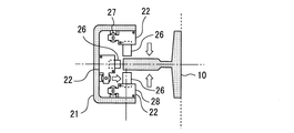
- FIG. 7 is a top view of the stopper unit 22 according to the first embodiment.
- FIG. 7 shows a state in which the gap between the stopper 26 and the car guide rail 10 is narrowed in each stopper unit 22.
- each stopper unit 22 suppresses the displacement of the car 8 from the front and rear sides and the left and right inner three directions, the displacement of the car 8 in the horizontal plane is suppressed.
- FIG. 8 is a flow chart showing an example of the operation of the elevator 1 according to the first embodiment.
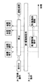
- 9 and 10 are diagrams showing an example of the operation timing of the elevator 1 according to the first embodiment.
- 11 and 12 are top views of the stopper unit 22 according to the first embodiment.
- the control panel 15 shifts the operation mode of the elevator 1 from the normal operation to the seismic control operation.
- the control panel 15 calculates the nearest floor on which the car 8 can stop.
- the control panel 15 outputs a control signal to the hoisting machine 6 so as to stop the car 8 on the calculated floor.
- the control panel 15 makes the car 8 stand by on the floor.
- the control unit 23 of the displacement suppressing device 18 acquires the stop position where the car 8 stops or the position of the restraint unit 13 closest to the stop position where the car 8 has already stopped.
- the control unit 23 calculates the relative position of the restraint unit 13 with respect to the car 8 stopped at the stop position.
- the command unit 25 of the control unit 23 outputs a command signal to the first drive unit 27 and the second drive unit 28 based on the calculated relative position and the like.
- FIG. 9 shows an example of the operation of the elevator 1 when an earthquake occurs while the car 8 is running.
- the earthquake detector 14 detects the occurrence of an earthquake after it has occurred.
- the earthquake detector 14 outputs a signal indicating the detection of an earthquake to the control panel 15.
- the control panel 15 shifts the operation mode to the seismic control operation.
- the control panel 15 starts decelerating the car 8 so as to move the car 8 to the nearest floor.
- the first drive unit 27 moves the stopper 26 in the vertical direction to the relative position of the restraint unit 13 calculated by the control unit 23 as an operation based on the command signal from the command unit 25.
- the second drive unit 28 moves the stopper 26 so as to narrow the gap between the car guide rail 10 and the stopper 26 as an operation based on the command signal from the command unit 25.
- the car 8 stops at the nearest floor based on the control by the control unit 23.
- the stopper 26 is moved to the relative position calculated by the control unit 23 by the first drive unit 27.
- the stopper 26 faces the restraint portion 13 of the car guide rail 10. Further, the gap between the car guide rail 10 and the stopper 26 is narrowed by the second drive unit 28.
- the gap between the stopper 26 and the restraint portion 13 is narrowed. Therefore, even when a horizontal seismic load or the like is applied to the car 8 through the car guide rail 10, the displacement of the car 8 is suppressed. Further, since the car guide rail 10 receives a reaction force from the car 8 at the restraint portion 13 in which the displacement in the horizontal direction is restrained, the car guide rail 10 is less likely to bend due to the reaction force from the car 8.
- the earthquake that occurred will converge.
- the convergence of the earthquake is sensed, for example, by the seismic detector 14.
- the control unit 23 outputs a command signal for canceling the operation to the first drive unit 27 and the second drive unit 28.
- the first drive unit 27 shifts to the standby state based on the command signal from the command unit 25.
- the first drive unit 27 maintains, for example, the relative position of the moved stopper 26 in the same relative position until the occurrence of the next earthquake is detected.
- the second drive unit 28 moves the stopper 26 so as to widen the gap between the car guide rail 10 and the stopper 26 based on the command signal from the command unit 25.
- the control panel 15 After that, if no abnormality has occurred in the elevator 1, for example, when the detected earthquake sway is smaller than the preset threshold value, the control panel 15 returns the operation mode to the normal operation.
- FIG. 10 shows an example of the operation of the elevator 1 when an earthquake occurs while the car 8 is stopped.
- the displacement suppressing device 18 operates in the same manner even when the car 8 is stopped. That is, the first drive unit 27 moves the stopper 26 in the vertical direction to the relative position of the restraint unit 13 calculated by the control unit 23 as an operation based on the command signal from the command unit 25. At the relative position, the stopper 26 faces the restraint portion 13 of the car guide rail 10. The second drive unit 28 moves the stopper 26 so as to narrow the gap between the car guide rail 10 and the stopper 26 as an operation based on the command signal from the command unit 25.
- the gap between the stopper 26 and the restraint portion 13 is narrowed. Therefore, even when a horizontal seismic load or the like is applied to the car 8 through the car guide rail 10, the displacement of the car 8 is suppressed. Further, since the car guide rail 10 receives a reaction force from the car 8 at the restraint portion 13 in which the displacement in the horizontal direction is restrained, the car guide rail 10 is less likely to bend due to the reaction force from the car 8.
- the control unit 23 outputs a command signal to the first drive unit 27 and the second drive unit 28 when the earthquake has converged.
- the first drive unit 27 shifts to the standby state based on the command signal from the command unit 25.
- the second drive unit 28 moves the stopper 26 so as to widen the gap between the car guide rail 10 and the stopper 26 based on the command signal from the command unit 25.
- 11 and 12 are top views of the stopper unit 22 according to the first embodiment.
- any one of the three stopper units 22 may be close to the car guide rail 10.
- the stopper 26 in the stopper unit 22 comes into contact with the car guide rail 10.
- the stopper 26 moves to a position close to the car guide rail 10 in the other two stopper units 22.
- the stopper unit 22 that was close to the car guide rail 10 also fluctuates. Move away from the guide rail 10.
- the stopper unit 22 can be moved to a position close to the car guide rail 10 to suppress the displacement.
- the displacement suppressing device 18 can arrange the car 8 at a normal position between the pair of car guide rails 10 without pushing back the car guide rail 10 with a large force by the stopper unit 22 or the like in the event of an earthquake or the like. After that, the displacement suppressing device 18 suppresses the displacement of the car 8 at the position.
- the displacement suppressing device 18 may be provided on the counterweight 9 which is an elevating body. At this time, the displacement suppressing device 18 provided on the counterweight 9 operates in the same manner as the displacement suppressing device 18 provided on the car 8 to suppress the displacement of the counterweight 9.
- the counterweight 9 may be connected with wiring for supplying power to the displacement suppressing device 18, signal communication, and the like.
- the counterweight 9 may be equipped with a battery or the like that supplies electric power to the displacement suppressing device 18.
- the displacement suppression device 18 may receive power supply and signal communication, for example, wirelessly.
- the restraint portion 13 of the guide rail may be, for example, a portion to which a connecting frame for horizontally connecting the pair of guide rails is attached.
- the connecting frame is a device that increases the rigidity of the pair of guide rails.
- the connecting frame may be a frame for connecting two pairs of guide rails of the pair of car guide rails 10 and the pair of counterweight guide rails 11 together.
- the connecting frame is, for example, a frame surrounding the car 8 and the counterweight 9 in the horizontal projection plane when the hoistway 3 is viewed from the vertical direction.
- the displacement suppressing device 18 includes a stopper unit 22.
- the stopper unit 22 is provided on the elevating body.
- the elevating body travels along the guide rail.
- the guide rail has a plurality of restraining portions 13.
- the elevating body stops at one of a plurality of stop positions in normal operation.
- the stopper unit 22 includes a stopper 26, a first drive unit 27, and a second drive unit 28.
- the stopper 26 faces the guide rail.
- the first drive unit 27 moves the relative position of the stopper 26 with respect to the elevating body in the traveling direction of the elevating body.
- the first drive unit 27 makes the stopper 26 face any of the restraint units 13.
- the second drive unit 28 changes the gap between the guide rail and the stopper 26 by moving the stopper 26.
- the second drive unit 28 suppresses the displacement of the elevating body by the stopper 26 that narrows the gap between the second drive unit 28 and the restraint unit 13.
- the stopper 26 whose gap with the guide rail is narrowed by the second drive unit 28 suppresses the displacement of the car 8 when a horizontal seismic load or the like is applied through the guide rail.
- the stopper 26 is moved to a relative position facing the restraint portion 13 by the first drive portion 27. Since the guide rail receives a reaction force from the car 8 at the restraint portion 13 in which the displacement in the horizontal direction is restrained, the guide rail is less likely to bend due to the reaction force from the car 8. Further, since the first drive unit 27 can move the relative position of the stopper 26 according to the restraint portion 13, the arrangement of the restraint portion 13 is not limited to the stop position of the elevating body or the like.
- the second drive unit 28 may have, for example, an actuator that directly moves the stopper 26 in the horizontal direction.
- the first drive unit 27 starts the movement of the stopper 26 to a relative position facing any of the restraint units 13.
- the first drive unit 27 operates when it is necessary to suppress the displacement of the relative position. Therefore, the energy for driving the first drive unit 27 is saved.
- the first drive unit 27 detects the occurrence of the next earthquake in the elevator 1 at the relative position where the stopper 26 is moved when the earthquake is occurring after the earthquake detected in the elevator 1 has converged.
- the stopper 26 is kept on standby until the earthquake is completed.
- the first drive unit 27 makes the stopper 26 stand by at a relative position that was moved when the previous earthquake occurred.
- building 2 the structure of each floor is often similar. Therefore, the relative positions of the restraint portions 13 closest to the stop position with respect to the elevating body stopped at the stop position are often similar on each floor. That is, the relative position of the stopper 26 when the previous earthquake occurred is often close to the relative position moved by the first drive unit 27 in the next earthquake. Therefore, there is a high possibility that the moving distance of the stopper 26 will be small when an earthquake occurs next time. As a result, the displacement suppressing device 18 can more quickly exert the effect of suppressing the displacement of the elevating body.
- the stopper 26 has a first slope 35 inclined with respect to the surface of the guide rail on the opposite side of the guide rail.
- the second drive unit 28 includes a moving piece 36.
- the moving piece 36 has a second slope 39 that is in contact with the first slope 35 and is parallel to the first slope 35.
- the second drive unit 28 changes the gap between the guide rail and the stopper 26 by moving the moving piece 36 in the moving direction of the elevating body and sliding the first slope 35 with respect to the second slope 39.
- the stopper unit 22 can be stored in the vertical pillar 21 or the like.
- the second drive unit 28 narrows the gap between the guide rail and the stopper 26 when the occurrence of an earthquake is detected in the elevator 1.
- the second drive unit 28 operates when it is necessary to suppress the displacement of the relative position. Therefore, the energy for driving the second drive unit 28 is saved. Further, since the gap between the guide rail and the stopper 26 is widened in the normal operation, it is difficult to hinder the traveling of the elevating body and the movement of the relative position of the stopper 26 in the elevating body.
- the displacement suppressing device 18 includes three stopper units 22.
- the three stopper units 22 operate independently of each other. In one of the three stopper units 22, the stopper 26 faces the front surface of the guide rail. In the other one of the three stopper units 22, the stopper 26 faces the rear surface of the guide rail. In the remaining one of the three stopper units 22, the stopper 26 faces the left and right inner side surfaces of the guide rail.
- each of the stopper units 22 operates independently, the car 8 can be arranged at a normal position between the pair of guide rails without pushing back the guide rails with a large force by utilizing shaking due to an earthquake or the like. Therefore, the size of each stopper unit 22 in the horizontal direction can be made compact. Therefore, the stopper unit 22 can be stored in the vertical pillar 21 or the like.
- FIG. 13 is a diagram showing an example of the operation timing of the elevator 1 according to the modified example of the first embodiment.
- the first drive unit 27 starts the movement of the stopper 26 to the preset standby position after the earthquake detected in the elevator 1 has converged.
- the standby position is a preset relative position based on the moving distance of the stopper 26 to the relative position facing the nearest restraint portion 13 among the plurality of restraint portions 13 at each stop position.
- the control unit 23 outputs a command signal for canceling the operation to the first drive unit 27.
- the first drive unit 27 shifts to the standby state based on the command signal from the command unit 25.
- the first drive unit 27 causes the stopper 26 to stand by at the standby position until the occurrence of the next earthquake is detected in the elevator 1.
- the standby position is set as follows, for example. First, the moving distance for the first drive unit 27 to move the stopper 26 when the elevating body stops at each stop position is calculated for each position relative to the elevating body. At this time, for example, the relative position where the average value or the total value of the movement distances for each floor is minimized is set as the standby position. Alternatively, for example, a relative position where the maximum value of the moving distance for each floor is minimized may be set as the standby position. Next, since the moving distance of the stopper 26 when an earthquake occurs becomes smaller, the displacement suppressing device 18 can more quickly exert the effect of suppressing the displacement of the elevating body.
- FIG. 14 is a hardware configuration diagram of a main part of the displacement suppressing device 18 according to the first embodiment.
- the processing circuit includes at least one processor 100a and at least one memory 100b.
- the processing circuit may include at least one dedicated hardware 200 with or as a substitute for the processor 100a and the memory 100b.
- each function of the displacement suppressing device 18 is realized by software, firmware, or a combination of software and firmware. At least one of the software and firmware is written as a program. The program is stored in the memory 100b. The processor 100a realizes each function of the displacement suppressing device 18 by reading and executing the program stored in the memory 100b.
- the processor 100a is also referred to as a CPU (Central Processing Unit), a processing device, an arithmetic unit, a microprocessor, a microcomputer, and a DSP.
- the memory 100b is composed of, for example, a non-volatile or volatile semiconductor memory such as a RAM, a ROM, a flash memory, an EPROM, or an EEPROM.
- the processing circuit includes the dedicated hardware 200
- the processing circuit is realized by, for example, a single circuit, a composite circuit, a programmed processor, a parallel programmed processor, an ASIC, an FPGA, or a combination thereof.
- Each function of the displacement suppression device 18 can be realized by a processing circuit. Alternatively, each function of the displacement suppressing device 18 can be collectively realized by a processing circuit. For each function of the displacement suppression device 18, a part may be realized by the dedicated hardware 200, and the other part may be realized by software or firmware. As described above, the processing circuit realizes each function of the displacement suppressing device 18 by the dedicated hardware 200, software, firmware, or a combination thereof.
- Embodiment 2 The differences between the second embodiment and the examples disclosed in the first embodiment will be described in particular detail. As for the features not described in the second embodiment, any of the features disclosed in the first embodiment may be adopted.
- the first drive unit 27 moves the stopper 26 to a relative position corresponding to the stop position in advance, so that the occurrence of an earthquake is detected.
- the effect of suppressing the displacement of the car 8 is exhibited more quickly.
- a configuration in which the first drive unit 27 moves the stopper 26 in the normal operation will be described.
- FIG. 15 is a flow chart showing an example of the operation of the elevator 1 according to the second embodiment.
- control panel 15 calculates the floor on which the traveling car 8 will stop next, for example, based on the call information to be made to respond to the car 8.
- the control unit 23 of the displacement suppression device 18 acquires the position of the restraint unit 13 closest to the stop position where the car 8 stops by referring to the storage unit 24.
- the control unit 23 calculates the relative position of the restraint unit 13 with respect to the car 8 stopped at the stop position.
- the command unit 25 of the control unit 23 outputs a command signal to the first drive unit 27 based on the calculated relative position and the like. Further, the command unit of the control unit 23 outputs a command signal to the second drive unit 28 when the occurrence of an earthquake is detected by the earthquake detector 14.
- FIG. 16 is a diagram showing an example of the operation timing of the elevator 1 according to the second embodiment.
- FIG. 16 shows an example of the operation of the elevator 1 when an earthquake occurs after the car 8 is stopped.
- the command unit 25 outputs a command signal to the first drive unit 27 when the deceleration of the car 8 is started so that the control panel 15 stops at the stop position in normal operation.
- the first drive unit 27 moves the stopper 26 in the vertical direction to the relative position of the restraint unit 13 calculated by the control unit 23 as an operation based on the command signal from the command unit 25. After that, the car 8 stops at the stop position. At this time, the stopper 26 is moved to the relative position calculated by the control unit 23 by the first drive unit 27.
- the earthquake detector 14 detects the occurrence of an earthquake after the occurrence of an earthquake.
- the earthquake detector 14 outputs a signal indicating the detection of an earthquake to the control panel 15.
- the control panel 15 shifts the operation mode to the seismic control operation.
- the command unit 25 outputs a command signal to the second drive unit 28.
- the second drive unit 28 moves the stopper 26 so as to narrow the gap between the car guide rail 10 and the stopper 26 as an operation based on the command signal from the command unit 25.
- the gap between the stopper 26 and the restraint portion 13 is narrowed. Therefore, even when a horizontal seismic load or the like is applied to the car 8 through the car guide rail 10, the displacement of the car 8 is suppressed. Further, since the car guide rail 10 receives a reaction force from the car 8 at the restraint portion 13 in which the displacement in the horizontal direction is restrained, the car guide rail 10 is less likely to bend due to the reaction force from the car 8.
- the control unit 23 outputs a command signal for canceling the operation to the first drive unit 27 and the second drive unit 28.
- the first drive unit 27 of the displacement suppression device 18 faces any restraint unit 13 when the elevating body stops at any stop position in normal operation. Move the stopper 26 to the relative position.
- the first drive unit 27 moves the stopper 26 to a relative position corresponding to the stop position in advance. As a result, the effect of suppressing the displacement of the elevating body when the occurrence of an earthquake is detected is exerted more quickly.
- the first drive unit 27 may start the movement of the stopper 26 before the elevating body decelerates. Alternatively, the first drive unit 27 may start the movement of the stopper 26 after the elevating body has stopped.
- Embodiment 3 The differences between the third embodiment and the examples disclosed in the first embodiment or the second embodiment will be described in particular detail. As for the features not described in the third embodiment, any of the features disclosed in the first embodiment or the second embodiment may be adopted.
- the first drive unit 27 Even when the car 8 is running, the stop position for stopping the car 8 in the event of an earthquake, the position of the restraint portion 13 closest to the stop position, and the relative position of the restraint portion 13 with respect to the car 8 are , Can be calculated before an earthquake occurs. Therefore, even in normal operation, the first drive unit 27 always moves the stopper 26 to a relative position corresponding to the stop position in advance, which has the effect of suppressing the displacement of the car 8 when the occurrence of an earthquake is detected. It will be exerted more quickly. In the third embodiment, the configuration in which the first drive unit 27 constantly moves the stopper 26 in the normal operation will be described.
- FIG. 17 is a diagram showing an example of the operation timing of the elevator 1 according to the third embodiment.
- control panel 15 calculates the nearest floor to stop the car 8 if an earthquake occurs, for example, based on the position and speed of the car 8.
- the control unit 23 of the displacement suppression device 18 acquires the position of the restraint unit 13 closest to the stop position where the car 8 stops by referring to the storage unit 24.
- the control unit 23 calculates the relative position of the restraint unit 13 with respect to the car 8 stopped at the stop position. For example, when the calculated relative position changes, the command unit 25 of the control unit 23 outputs a command signal to the first drive unit 27.
- the command unit 25 constantly outputs a command signal to the first drive unit 27 regardless of whether or not the occurrence of an earthquake is detected.
- the first drive unit 27 moves the stopper 26 in the vertical direction to the relative position of the restraint unit 13 calculated by the control unit 23 as an operation based on the command signal from the command unit 25.
- the earthquake detector 14 detects the occurrence of an earthquake after it has occurred.
- the earthquake detector 14 outputs a signal indicating the detection of an earthquake to the control panel 15.
- the control panel 15 shifts the operation mode to the seismic control operation.
- the command unit 25 outputs a command signal to the second drive unit 28.
- the second drive unit 28 moves the stopper 26 so as to narrow the gap between the car guide rail 10 and the stopper 26 as an operation based on the command signal from the command unit 25.
- the gap between the stopper 26 and the restraint portion 13 is narrowed. Therefore, even when a horizontal seismic load or the like is applied to the car 8 through the car guide rail 10, the displacement of the car 8 is suppressed. Further, since the car guide rail 10 receives a reaction force from the car 8 at the restraint portion 13 in which the displacement in the horizontal direction is restrained, the car guide rail 10 is less likely to bend due to the reaction force from the car 8.
- the control unit 23 outputs a command signal for canceling the operation to the second drive unit 28.
- the first drive unit 27 of the displacement suppressing device 18 is set to a relative position corresponding to the current position of the elevating body when the elevating body is traveling in normal operation.
- the relative position for moving the stopper 26 is such that when the elevating body stops from the current position, the movement distance of the stopper 26 to the relative position facing the nearest restraint portion 13 among the plurality of restraint portions 13 is the smallest. Relative position.
- the first drive unit 27 always moves the stopper 26 in advance to a relative position corresponding to the current position of the elevating body even in normal operation.
- the effect of suppressing the displacement of the elevating body when the occurrence of an earthquake is detected is exerted more quickly.
- the displacement of the elevating body is suppressed more effectively.
- Embodiment 4 In the fourth embodiment, the differences from the examples disclosed in the first to third embodiments will be described in particular detail. As for the features not described in the fourth embodiment, any of the features disclosed in the first to third embodiments may be adopted.
- the gap between the car guide rail 10 and the stopper 26 is narrowed even in normal operation, the effect of suppressing the displacement of the car 8 when the occurrence of an earthquake is detected is exhibited more quickly.
- the stopper 26 comes into contact with the car guide rail 10, the running of the car 8 may be hindered.
- the gap can be adjusted so that the running of the car 8 is not hindered.
- a configuration for measuring and adjusting the gap between the car guide rail 10 and the stopper 26 will be described.
- FIG 18 and 19 are top views of the stopper unit 22 according to the fourth embodiment.
- the displacement suppressing device 18 includes a measuring unit 40.
- the measuring unit 40 is a portion that measures the gap between the car guide rail 10 and the stopper 26.
- the measuring unit 40 includes a sensor for measuring the gap in the front-rear direction and a sensor for measuring the gap in the left-right direction. Based on the measurement result of the gap between one surface of the front surface or the rear surface of the car guide rail 10 and the stopper 26 facing the surface, the measuring unit 40 has the other surface and the surface of the front surface or the rear surface of the car guide rail 10. The gap between the stopper 26 and the stopper 26 may be calculated.
- the measuring unit 40 measures the gap by, for example, a non-contact type distance sensor.
- the measuring unit 40 may be provided with individual sensors corresponding to one-to-one in each stopper unit 22.
- the storage unit 24 of the control unit 23 stores the first threshold value and the second threshold value.
- the first threshold value is a threshold value preset with respect to the gap between the car guide rail 10 and the stopper 26 so as to prevent contact between the car guide rail 10 and the stopper 26.
- the second threshold value is a threshold value preset with respect to the gap between the car guide rail 10 and the stopper 26 so as to suppress the displacement of the car 8.
- the value of the second threshold value is equal to or higher than the value of the first threshold value.
- the second drive unit 28 has an actuator 41 that directly moves the stopper 26 in the horizontal direction.
- the gap between the car guide rail 10 and the stopper 26 is adjusted by, for example, the actuator 41 of the second drive unit 28.
- the configuration of the second drive unit 28 may be the same as the configuration shown in the first embodiment or the like.
- the gap between the car guide rail 10 and the stopper 26 is narrowed by the second drive unit 28.
- the gap between the car guide rail 10 and the stopper 26 may fluctuate due to vibration or the like accompanying the running of the car 8.
- the second driving unit 28 widens the gap between the car guide rail 10 and the stopper 26 by, for example, an actuator 41.
- the second driving unit 28 narrows the gap between the car guide rail 10 and the stopper 26 by, for example, an actuator 41.
- the gap between the car guide rail 10 and the stopper 26 that can suppress the displacement of the car 8 is maintained in normal operation.
- the second drive unit 28 keeps the gap between the guide rail and the stopper 26 narrow in the car 8 regardless of the measurement by the measurement unit 40. As a result, the displacement of the car 8 due to the shaking of the earthquake or the like is suppressed through the car guide rail 10.
- the displacement suppressing device 18 includes a measuring unit 40.
- the measuring unit 40 measures the gap between the guide rail and the stopper 26.
- the second drive unit 28 widens the gap between the guide rail and the stopper 26 when the gap measured by the measurement unit 40 is smaller than the preset first threshold value in normal operation.
- the second drive unit 28 determines the position of the stopper 26 in a state where the gap with the guide rail is narrowed regardless of the size of the gap measured by the measurement unit 40. maintain.
- the gap is adjusted in normal operation so that the traveling of the elevating body is not hindered based on the measurement result of the gap between the guide rail and the stopper 26.
- the gap between the guide rail and the stopper 26 can be narrowed in advance even in normal operation. Therefore, the effect of suppressing the displacement of the elevating body when the occurrence of an earthquake is detected is exhibited more quickly.
- the displacement suppression device according to the present disclosure can be applied to an elevator body.
Landscapes
- Engineering & Computer Science (AREA)
- Civil Engineering (AREA)
- Mechanical Engineering (AREA)
- Structural Engineering (AREA)
- Maintenance And Inspection Apparatuses For Elevators (AREA)
- Cage And Drive Apparatuses For Elevators (AREA)
Priority Applications (3)
| Application Number | Priority Date | Filing Date | Title |
|---|---|---|---|
| PCT/JP2020/026272 WO2022003979A1 (ja) | 2020-07-03 | 2020-07-03 | エレベーターの昇降体の変位抑制装置 |
| CN202080102492.9A CN115734934B (zh) | 2020-07-03 | 2020-07-03 | 电梯的升降体的位移抑制装置 |
| JP2022533015A JP7327670B2 (ja) | 2020-07-03 | 2020-07-03 | エレベーターの昇降体の変位抑制装置 |
Applications Claiming Priority (1)
| Application Number | Priority Date | Filing Date | Title |
|---|---|---|---|
| PCT/JP2020/026272 WO2022003979A1 (ja) | 2020-07-03 | 2020-07-03 | エレベーターの昇降体の変位抑制装置 |
Publications (1)
| Publication Number | Publication Date |
|---|---|
| WO2022003979A1 true WO2022003979A1 (ja) | 2022-01-06 |
Family
ID=79314996
Family Applications (1)
| Application Number | Title | Priority Date | Filing Date |
|---|---|---|---|
| PCT/JP2020/026272 Ceased WO2022003979A1 (ja) | 2020-07-03 | 2020-07-03 | エレベーターの昇降体の変位抑制装置 |
Country Status (3)
| Country | Link |
|---|---|
| JP (1) | JP7327670B2 (https=) |
| CN (1) | CN115734934B (https=) |
| WO (1) | WO2022003979A1 (https=) |
Families Citing this family (1)
| Publication number | Priority date | Publication date | Assignee | Title |
|---|---|---|---|---|
| CN117142284B (zh) * | 2023-11-01 | 2024-01-23 | 菱王电梯有限公司 | 电梯的安全钳检测方法、系统、电梯、设备及介质 |
Citations (7)
| Publication number | Priority date | Publication date | Assignee | Title |
|---|---|---|---|---|
| JP2005060001A (ja) * | 2003-08-08 | 2005-03-10 | Toshiba Elevator Co Ltd | エレベータの案内装置 |
| JP2007521201A (ja) * | 2003-09-09 | 2007-08-02 | オーチス エレベータ カンパニー | 引込み式地震プレート |
| WO2011039854A1 (ja) * | 2009-09-30 | 2011-04-07 | 三菱電機株式会社 | エレベータのかご枠 |
| JP2014201429A (ja) * | 2013-04-10 | 2014-10-27 | 株式会社日立製作所 | 制振装置付きエレベータ |
| JP2015137170A (ja) * | 2014-01-23 | 2015-07-30 | 株式会社日立ビルシステム | エレベータ装置 |
| JP2016216254A (ja) * | 2015-05-26 | 2016-12-22 | 東芝エレベータ株式会社 | エレベータのコンペンシーブ支持構造体 |
| JP2018162165A (ja) * | 2018-07-25 | 2018-10-18 | フジテック株式会社 | エレベータ用のかご横揺れ抑制装置 |
Family Cites Families (5)
| Publication number | Priority date | Publication date | Assignee | Title |
|---|---|---|---|---|
| JP4265837B2 (ja) * | 1999-04-20 | 2009-05-20 | 三菱電機株式会社 | 免震建築用エレベーター装置 |
| JP2004231342A (ja) * | 2003-01-29 | 2004-08-19 | Hitachi Ltd | エレベータのレール外れ止め装置 |
| CN101102955B (zh) * | 2006-01-10 | 2010-05-19 | 三菱电机株式会社 | 电梯装置 |
| WO2018030155A1 (ja) * | 2016-08-09 | 2018-02-15 | 三菱電機株式会社 | エレベーター装置 |
| CN207330039U (zh) * | 2017-09-13 | 2018-05-08 | 上海现代电梯制造有限公司 | 一种导轨弯曲抑制装置 |
-
2020
- 2020-07-03 WO PCT/JP2020/026272 patent/WO2022003979A1/ja not_active Ceased
- 2020-07-03 JP JP2022533015A patent/JP7327670B2/ja active Active
- 2020-07-03 CN CN202080102492.9A patent/CN115734934B/zh active Active
Patent Citations (7)
| Publication number | Priority date | Publication date | Assignee | Title |
|---|---|---|---|---|
| JP2005060001A (ja) * | 2003-08-08 | 2005-03-10 | Toshiba Elevator Co Ltd | エレベータの案内装置 |
| JP2007521201A (ja) * | 2003-09-09 | 2007-08-02 | オーチス エレベータ カンパニー | 引込み式地震プレート |
| WO2011039854A1 (ja) * | 2009-09-30 | 2011-04-07 | 三菱電機株式会社 | エレベータのかご枠 |
| JP2014201429A (ja) * | 2013-04-10 | 2014-10-27 | 株式会社日立製作所 | 制振装置付きエレベータ |
| JP2015137170A (ja) * | 2014-01-23 | 2015-07-30 | 株式会社日立ビルシステム | エレベータ装置 |
| JP2016216254A (ja) * | 2015-05-26 | 2016-12-22 | 東芝エレベータ株式会社 | エレベータのコンペンシーブ支持構造体 |
| JP2018162165A (ja) * | 2018-07-25 | 2018-10-18 | フジテック株式会社 | エレベータ用のかご横揺れ抑制装置 |
Also Published As
| Publication number | Publication date |
|---|---|
| CN115734934A (zh) | 2023-03-03 |
| CN115734934B (zh) | 2025-12-02 |
| JPWO2022003979A1 (https=) | 2022-01-06 |
| JP7327670B2 (ja) | 2023-08-16 |
Similar Documents
| Publication | Publication Date | Title |
|---|---|---|
| US12280984B2 (en) | Elevator system | |
| CN103459289B (zh) | 电梯装置 | |
| CN100343152C (zh) | 电梯的导向装置 | |
| US20150251877A1 (en) | Elevator apparatus | |
| US11286132B2 (en) | Enhancing the transport capacity of an elevator system | |
| JP5963335B1 (ja) | エレベータ用速度検出装置およびエレベータ | |
| JP2008094597A (ja) | マルチカーエレベーター | |
| US9764927B2 (en) | Elevator | |
| JPWO2016038681A1 (ja) | エレベーター装置 | |
| JP4566587B2 (ja) | エレベータの制御装置 | |
| WO2022003979A1 (ja) | エレベーターの昇降体の変位抑制装置 | |
| KR102330456B1 (ko) | 로프리스 엘리베이터 시스템 | |
| KR20210085850A (ko) | 로프리스 엘리베이터 시스템 | |
| KR20210085852A (ko) | 로프리스 엘리베이터 시스템 | |
| KR102330510B1 (ko) | 로프리스 엘리베이터 시스템 | |
| JP6799021B2 (ja) | ガバナテンション機構、ガバナ装置及びエレベーター | |
| JP5829869B2 (ja) | エレベータの非常停止装置 | |
| JP7435780B2 (ja) | エレベーターの昇降体の変位抑制装置 | |
| JP2022154393A (ja) | エレベータ、調速機及び釣合錘 | |
| JP4302062B2 (ja) | エレベータ装置 | |
| CN115803277B (en) | Displacement suppressing device for elevator lifting body | |
| KR20210085853A (ko) | 로프리스 엘리베이터 시스템 | |
| CN114955759B (zh) | 电梯系统 | |
| JP5264145B2 (ja) | エレベータ制御装置 | |
| JP2015000767A (ja) | エレベータ制動装置 |
Legal Events
| Date | Code | Title | Description |
|---|---|---|---|
| 121 | Ep: the epo has been informed by wipo that ep was designated in this application |
Ref document number: 20942529 Country of ref document: EP Kind code of ref document: A1 |
|
| ENP | Entry into the national phase |
Ref document number: 2022533015 Country of ref document: JP Kind code of ref document: A |
|
| NENP | Non-entry into the national phase |
Ref country code: DE |
|
| 122 | Ep: pct application non-entry in european phase |
Ref document number: 20942529 Country of ref document: EP Kind code of ref document: A1 |