WO2022003979A1 - Elevator ascending/descending body displacement suppression device - Google Patents
Elevator ascending/descending body displacement suppression device Download PDFInfo
- Publication number
- WO2022003979A1 WO2022003979A1 PCT/JP2020/026272 JP2020026272W WO2022003979A1 WO 2022003979 A1 WO2022003979 A1 WO 2022003979A1 JP 2020026272 W JP2020026272 W JP 2020026272W WO 2022003979 A1 WO2022003979 A1 WO 2022003979A1
- Authority
- WO
- WIPO (PCT)
- Prior art keywords
- stopper
- guide rail
- elevator
- car
- drive unit
- Prior art date
Links
Images


Classifications
-
- B—PERFORMING OPERATIONS; TRANSPORTING
- B66—HOISTING; LIFTING; HAULING
- B66B—ELEVATORS; ESCALATORS OR MOVING WALKWAYS
- B66B11/00—Main component parts of lifts in, or associated with, buildings or other structures
- B66B11/02—Cages, i.e. cars
-
- B—PERFORMING OPERATIONS; TRANSPORTING
- B66—HOISTING; LIFTING; HAULING
- B66B—ELEVATORS; ESCALATORS OR MOVING WALKWAYS
- B66B7/00—Other common features of elevators
- B66B7/02—Guideways; Guides
Definitions
- This disclosure relates to a displacement suppressing device for an elevator elevator.
- Patent Document 1 discloses an example of an elevator.
- a seismic plate is installed in the car.
- the seismic plate works with the guide rails to reduce lateral displacement of the car.
- the guide rail may bend due to the reaction force received from the elevating body such as a car.
- the present disclosure provides a displacement suppressing device for an elevator elevator whose guide rail is less likely to bend due to a reaction force received from the elevator.
- the displacement suppressing device for an elevator elevating body includes a stopper unit provided on the elevator elevating body that travels along a guide rail having a plurality of restraining portions and stops at one of a plurality of stop positions in normal operation.
- the stopper unit includes a stopper facing the guide rail, a first drive unit that moves the relative position of the stopper with respect to the elevating body in the traveling direction of the elevating body, and makes the stopper face any of a plurality of restraining parts, and a stopper.
- a second drive unit is provided, which changes the gap between the guide rail and the stopper by moving the guide rail and suppresses the displacement of the elevating body by a stopper that narrows the gap between the guide rail and the stopper.
- the guide rail is less likely to bend due to the reaction force received from the elevating body.
- FIG. It is a block diagram of the elevator which concerns on Embodiment 1.
- FIG. It is a front view of the car which concerns on Embodiment 1.
- FIG. It is a top view of the stopper unit which concerns on Embodiment 1.
- FIG. It is a side view of the stopper unit which concerns on Embodiment 1.
- FIG. It is a block diagram of the stopper unit which concerns on Embodiment 1.
- FIG. It is a block diagram of the stopper unit which concerns on Embodiment 1.
- FIG. It is a top view of the stopper unit which concerns on Embodiment 1.
- FIG. It is a flow chart which shows the example of the operation of the elevator which concerns on Embodiment 1.
- FIG. It is a front view of the car which concerns on Embodiment 1.
- FIG. It is a top view of the stopper unit which concerns on Embodiment 1.
- FIG. It is a side view of the stopper unit which concerns on Embodiment 1.
- FIG.
- FIG. It is a figure which shows the example of the operation timing of the elevator which concerns on Embodiment 1.
- FIG. It is a figure which shows the example of the operation timing of the elevator which concerns on Embodiment 1.
- FIG. It is a top view of the stopper unit which concerns on Embodiment 1.
- FIG. It is a top view of the stopper unit which concerns on Embodiment 1.
- FIG. It is a figure which shows the example of the operation timing of the elevator 1 which concerns on the modification of Embodiment 1.
- FIG. It is a hardware block diagram of the main part of the displacement suppression apparatus which concerns on Embodiment 1.
- FIG. It is a flow chart which shows the example of the operation of the elevator which concerns on Embodiment 2.
- FIG. 1 It is a figure which shows the example of the operation timing of the elevator which concerns on Embodiment 2.
- FIG. It is a figure which shows the example of the operation timing of the elevator which concerns on Embodiment 3.
- FIG. It is a top view of the stopper unit which concerns on Embodiment 4.
- FIG. It is a top view of the stopper unit which concerns on Embodiment 4.
- FIG. 1 is a configuration diagram of an elevator 1 according to the first embodiment.
- the elevator 1 is installed in a building 2 having a plurality of floors.
- a hoistway 3 is provided in the building 2.
- the hoistway 3 is a space that spans a plurality of floors.
- the machine room 4 is provided above the hoistway 3.
- a pit 5 is provided at the bottom of the hoistway 3.
- Elevator 1 includes a hoist 6, a main rope 7, a basket 8, and a counterweight 9.
- the hoisting machine 6 includes a sheave and a motor.
- the motor of the hoisting machine 6 is a device for rotating and driving the sheave of the hoisting machine 6.
- the hoisting machine 6 is provided in, for example, the machine room 4.
- the main rope 7 is wound around the sheave of the hoist 6. One end of the main rope 7 is connected to the car 8. The other end of the main rope 7 is connected to the counterweight 9.
- the elevator 1 may include a plurality of main ropes 7.
- the car 8 is a device for transporting a user or the like between a plurality of floors by traveling in the vertical direction on the hoistway 3.
- the counterweight 9 is a device that balances the load applied to both sides of the sheave of the hoist 6 through the main rope 7 with the car 8.
- the car 8 and the counterweight 9 are suspended in the hoistway 3 by the main rope 7.
- the car 8 and the counterweight 9 travel on the hoistway 3 in opposite directions by the hoisting machine 6 winding up the main rope 7.
- Each of the cage 8 and the counterweight 9 is an example of an elevating body.
- a pair of car guide rails 10, a pair of counterweight guide rails 11, and a plurality of brackets 12 are provided.
- the pair of car guide rails 10 is a pair of guide rails that guide the traveling of the car 8 on the hoistway 3. Each car guide rail 10 is arranged along the vertical direction in the hoistway 3. One car guide rail 10 is arranged on the left side of the car 8. The other car guide rail 10 is arranged on the right side of the car 8.
- the pair of counterweight guide rails 11 is a pair of guide rails that guide the traveling of the counterweight 9 on the hoistway 3. Each counterweight guide rail 11 is arranged along the vertical direction in the hoistway 3. One of the counterweight guide rails 11 is arranged on the left side of the counterweight 9. The other counterbalance weight guide rail 11 is arranged on the right side of the counterbalance weight 9.
- the elevating body such as the car 8 or the counterweight 9 travels in the vertical direction along the guide rail such as the car guide rail 10 or the counterweight guide rail 11.
- Each of the guide rails that guide the traveling of the elevating body is fixed to the hoistway 3 by the plurality of brackets 12.
- Each guide rail has a plurality of restraint portions 13.
- Each restraint portion 13 is a portion where the horizontal displacement of the guide rail is constrained.
- the restraint portion 13 is, for example, a portion fixed by the bracket 12 on the guide rail.
- the distance between the brackets 12 in the vertical direction in the hoistway 3 is shorter than, for example, the height of the car 8.
- each bracket 12 may be arranged corresponding to any of the stop positions of the elevating body.
- Elevator 1 includes an earthquake detector 14 and a control panel 15.
- the earthquake detector 14 is a part that detects the occurrence of an earthquake.
- the seismic detector 14 is provided, for example, in the pit 5.
- the seismic detector 14 is a P wave detector that detects an earthquake by, for example, a P wave (Primary wave).
- the seismic detector 14 is provided, for example, in the machine room 4.
- the earthquake detector 14 is an S wave detector that detects an earthquake by, for example, an S wave (Secondary wave).
- the seismic detector 14 may be provided in both the pit 5 and the machine room 4.
- the control panel 15 is a device that controls the operation of the elevator 1.
- the control panel 15 is provided in, for example, the machine room 4.
- the control panel 15 controls the traveling of the car 8 and the counterweight 9 by, for example, controlling the operation of the hoisting machine 6.
- the control panel 15 manages the operation mode of the elevator 1.
- the operation mode of the elevator 1 includes normal operation and seismic control operation.
- the normal operation is an operation mode in which the car 8 is driven so as to answer a call or the like registered by the user. In normal operation, the car 8 stops at one of a plurality of floors. The position of each floor is an example of the stop position in normal operation for the car 8. Further, when the car 8 stops on any floor, the counterweight 9 stops at a position corresponding to the floor.
- the position where the counterweight 9 stops corresponding to each floor is an example of the stop position in the normal operation of the counterweight 9.
- the earthquake control operation is an operation mode when the occurrence of an earthquake is detected in the elevator 1 by, for example, an earthquake detector 14.
- the control panel 15 stops, for example, the traveling car 8 on the nearest floor.
- the detection of the occurrence of an earthquake in the elevator 1 may be performed based on information such as an earthquake occurrence forecast or warning provided from the outside of the elevator 1 such as an Earthquake Early Warning.
- the detection of the occurrence of an earthquake in the elevator 1 may be performed, for example, by receiving a signal for seismic detection by an earthquake detector provided in a building closer to the epicenter than the building 2.
- FIG. 2 is a front view of the car 8 according to the first embodiment.
- the car 8 includes a car frame 16, a plurality of guide shoes 17, and a displacement suppressing device 18.
- the car frame 16 includes an upper beam 19, a lower beam 20, and a pair of vertical columns 21.
- the upper beam 19 is a member arranged between the left end portion and the right end portion in the upper part of the car 8.
- the lower beam 20 is a member arranged between the left end portion and the right end portion in the lower part of the car 8.
- the pair of vertical columns 21 are members arranged between the upper beam 19 and the lower beam 20.
- One vertical pillar 21 is arranged at the left end of the car 8.
- the other vertical pillar 21 is arranged at the right end of the car 8.
- the left vertical pillar 21 is arranged along the left car guide rail 10 of the car 8.
- the vertical pillar 21 on the right side is arranged along the car guide rail 10 on the right side of the car 8.
- the plurality of guide shoes 17 are portions guided by a pair of car guide rails 10. Each guide shoe 17 faces one of the car guide rails 10. Each guide shoe 17 is attached to, for example, a car frame 16. Each guide shoe 17 is arranged, for example, at the left end portion or the right end portion of the upper beam 19 or the lower beam 20.
- the displacement suppressing device 18 is a device that suppresses the horizontal displacement of an elevating body such as a car 8.
- the displacement suppressing device 18 includes a plurality of stopper units 22 and a control unit 23.
- Each stopper unit 22 is a portion that regulates the displacement of the car 8 by the car guide rail 10.
- Each stopper unit 22 is attached to, for example, the upper part or the lower part of any of the vertical columns 21.
- the control unit 23 is a part that controls the operation of each stopper unit 22.
- the control unit 23 is mounted on, for example, the control panel 15 of the elevator 1.
- the control unit 23 may be provided, for example, on the upper part of the car 8.
- the displacement suppressing device 18 may be provided with individual control units 23 corresponding to one-to-one in each stopper unit 22.
- the control unit 23 includes a storage unit 24 and a command unit 25.
- the storage unit 24 is a portion that stores information. In the storage unit 24, for example, the positions of the plurality of restraint units 13 on the car guide rail 10 are stored.
- the command unit 25 is a unit that outputs a command signal to each stopper unit 22 based on the input information, the information stored in the storage unit 24, and the like.
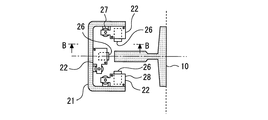
- FIG. 3 is a top view of the stopper unit 22 according to the first embodiment.
- FIG. 3 shows a cross-sectional view taken along the line AA in FIG.
- stopper units 22 are attached to the upper part of each vertical pillar 21. Further, three stopper units 22 are similarly provided at the lower part of each vertical pillar 21. In FIG. 3, the upper three stopper units 22 are shown. Each stopper unit 22 operates independently of each other.
- Each stopper unit 22 includes a stopper 26.
- the stopper 26 is a member facing the surface of the car guide rail 10. In one of the three stopper units 22, the stopper 26 faces the front surface of the car guide rail 10. In the other one of the three stopper units 22, the stopper 26 faces the rear surface of the car guide rail 10. In the remaining one of the three stopper units 22, the stopper 26 faces the left and right inner side surfaces of the car guide rail 10. Here, the left and right inner side surfaces are the side surfaces on the car 8 side.
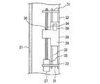
- FIG. 4 is a side view of the stopper unit 22 according to the first embodiment.
- FIG. 4 shows a sectional view taken along the line BB in FIG.
- Each stopper unit 22 includes a first drive unit 27 and a second drive unit 28.
- the first drive unit 27 is a portion that moves the relative position of the stopper 26 with respect to the car 8 in the vertical direction.
- the second drive unit 28 is a portion that changes the gap between the car guide rail 10 and the stopper 26 by moving the stopper 26.
- the second drive unit 28 includes a frame 29.
- the frame 29 is a portion that holds the stopper 26.
- a screw hole 30 is provided in the vertical direction.
- the first drive unit 27 includes a pair of bearings 31, a guide shaft 32, a drive motor 33, and a ball screw 34.
- the pair of bearings 31 are arranged above and below the range of movement of the relative position of the stopper 26 by the first drive unit 27.
- the guide shaft 32 is arranged parallel to the vertical column 21 between the pair of bearings 31.
- the first drive unit 27 may include a plurality of guide shafts 32 parallel to each other.
- the drive motor 33 is attached to one of the bearings 31.
- the ball screw 34 is arranged parallel to the guide shaft 32 between the other bearing 31 and the drive motor 33.
- the ball screw 34 is passed through the screw hole 30 of the frame 29 of the second drive unit 28.
- the first drive unit 27 rotates the ball screw 34 by the drive motor 33 based on the control of the control unit 23, so that the stopper 26 is moved in the vertical direction together with the second drive unit 28.
- the first drive unit 27 may move the relative position of the stopper 26 in the vertical direction by another method.
- the first drive unit 27 may have a linear motor for moving the frame 29 or the like in the vertical direction, a hydraulic or pneumatic cylinder, or the like.
- FIG. 5 is a configuration diagram of the stopper unit 22 according to the first embodiment.
- FIG. 5 shows a side view of the internal structure of the second drive unit 28.
- the stopper 26 faces the surface of the car guide rail 10 with a vertical surface parallel to the surface of the car guide rail 10.
- the stopper 26 has a vertical surface and a first slope 35 on the opposite side of the car guide rail 10.
- the first slope 35 is a surface that is inclined with respect to the surface of the car guide rail 10.
- the first slope 35 is, for example, a surface inclined downward.
- the first slope 35 is provided below the vertical surface on the opposite side of the car guide rail 10.
- the stopper 26 is movably held so that the gap between the stopper 26 and the car guide rail 10 can be changed by the guidance of the frame 29.
- the stopper 26 is guided to move downward when it leaves the car guide rail 10.
- FIG. 5 shows a state in which the gap between the stopper 26 and the car guide rail 10 is widened.
- the second drive unit 28 includes a moving piece 36, a push-up spring 37, and an actuator 38.
- the moving piece 36 is a portion that is movably held in the vertical direction by the guidance of the frame 29.
- the moving piece 36 has a second slope 39 at the upper end thereof.
- the second slope 39 is a plane parallel to the first slope 35.
- the second slope 39 comes into contact with the first slope 35 in a state where the gap between the car guide rail 10 and the stopper 26 is widened.
- the moving piece 36 has a vertical surface that descends downward from the stopper 26 side of the second slope 39.
- the push-up spring 37 is arranged in contact with the lower end of the moving piece 36.
- the central axis of the push-up spring 37 is oriented in the vertical direction.
- the push-up spring 37 is compressed in a state where the gap between the car guide rail 10 and the stopper 26 is widened.
- the actuator 38 is a portion that changes the gap between the car guide rail 10 and the stopper 26 by moving the moving piece 36 in the vertical direction based on the control of the control unit 23.
- the actuator 38 pushes down the moving piece 36 in the vertical direction while resisting the elastic force of the push-up spring 37.
- the movement of the moving piece 36 creates a space inside the frame 29 on the opposite side of the car guide rail 10 of the stopper 26.
- the stopper 26 moves in a direction away from the car guide rail 10 due to, for example, its own weight.
- the stopper 26 may be moved in a direction away from the car guide rail 10 by magnetic force by providing a magnet or the like on the stopper 26 and the moving piece 36 or the frame 29.
- FIG. 6 is a configuration diagram of the stopper unit 22 according to the first embodiment.
- FIG. 6 shows a side view of the internal structure of the second drive unit 28.
- the actuator 38 releases the moving piece 36 that has been pushed down.
- the moving piece 36 is pushed up in the vertical direction by the push-up spring 37.
- the second slope 39 of the moving piece 36 comes into contact with the first slope 35 of the stopper 26 and slides.
- the stopper 26 moves in a direction approaching the car guide rail 10 while being pushed by the moving piece 36 and being guided by the frame 29.
- the vertical surface of the stopper 26 on the opposite side of the car guide rail 10 and the vertical surface of the moving piece 36 come into contact with each other.
- the movement of the stopper 26 in the direction away from the car guide rail 10 is restricted by the moving piece 36. Therefore, even when a horizontal seismic load or the like is applied to the car 8 through the car guide rail 10, the displacement of the car 8 is suppressed.
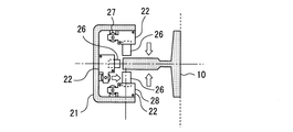
- FIG. 7 is a top view of the stopper unit 22 according to the first embodiment.
- FIG. 7 shows a state in which the gap between the stopper 26 and the car guide rail 10 is narrowed in each stopper unit 22.
- each stopper unit 22 suppresses the displacement of the car 8 from the front and rear sides and the left and right inner three directions, the displacement of the car 8 in the horizontal plane is suppressed.
- FIG. 8 is a flow chart showing an example of the operation of the elevator 1 according to the first embodiment.
- 9 and 10 are diagrams showing an example of the operation timing of the elevator 1 according to the first embodiment.
- 11 and 12 are top views of the stopper unit 22 according to the first embodiment.
- the control panel 15 shifts the operation mode of the elevator 1 from the normal operation to the seismic control operation.
- the control panel 15 calculates the nearest floor on which the car 8 can stop.
- the control panel 15 outputs a control signal to the hoisting machine 6 so as to stop the car 8 on the calculated floor.
- the control panel 15 makes the car 8 stand by on the floor.
- the control unit 23 of the displacement suppressing device 18 acquires the stop position where the car 8 stops or the position of the restraint unit 13 closest to the stop position where the car 8 has already stopped.
- the control unit 23 calculates the relative position of the restraint unit 13 with respect to the car 8 stopped at the stop position.
- the command unit 25 of the control unit 23 outputs a command signal to the first drive unit 27 and the second drive unit 28 based on the calculated relative position and the like.
- FIG. 9 shows an example of the operation of the elevator 1 when an earthquake occurs while the car 8 is running.
- the earthquake detector 14 detects the occurrence of an earthquake after it has occurred.
- the earthquake detector 14 outputs a signal indicating the detection of an earthquake to the control panel 15.
- the control panel 15 shifts the operation mode to the seismic control operation.
- the control panel 15 starts decelerating the car 8 so as to move the car 8 to the nearest floor.
- the first drive unit 27 moves the stopper 26 in the vertical direction to the relative position of the restraint unit 13 calculated by the control unit 23 as an operation based on the command signal from the command unit 25.
- the second drive unit 28 moves the stopper 26 so as to narrow the gap between the car guide rail 10 and the stopper 26 as an operation based on the command signal from the command unit 25.
- the car 8 stops at the nearest floor based on the control by the control unit 23.
- the stopper 26 is moved to the relative position calculated by the control unit 23 by the first drive unit 27.
- the stopper 26 faces the restraint portion 13 of the car guide rail 10. Further, the gap between the car guide rail 10 and the stopper 26 is narrowed by the second drive unit 28.
- the gap between the stopper 26 and the restraint portion 13 is narrowed. Therefore, even when a horizontal seismic load or the like is applied to the car 8 through the car guide rail 10, the displacement of the car 8 is suppressed. Further, since the car guide rail 10 receives a reaction force from the car 8 at the restraint portion 13 in which the displacement in the horizontal direction is restrained, the car guide rail 10 is less likely to bend due to the reaction force from the car 8.
- the earthquake that occurred will converge.
- the convergence of the earthquake is sensed, for example, by the seismic detector 14.
- the control unit 23 outputs a command signal for canceling the operation to the first drive unit 27 and the second drive unit 28.
- the first drive unit 27 shifts to the standby state based on the command signal from the command unit 25.
- the first drive unit 27 maintains, for example, the relative position of the moved stopper 26 in the same relative position until the occurrence of the next earthquake is detected.
- the second drive unit 28 moves the stopper 26 so as to widen the gap between the car guide rail 10 and the stopper 26 based on the command signal from the command unit 25.
- the control panel 15 After that, if no abnormality has occurred in the elevator 1, for example, when the detected earthquake sway is smaller than the preset threshold value, the control panel 15 returns the operation mode to the normal operation.
- FIG. 10 shows an example of the operation of the elevator 1 when an earthquake occurs while the car 8 is stopped.
- the displacement suppressing device 18 operates in the same manner even when the car 8 is stopped. That is, the first drive unit 27 moves the stopper 26 in the vertical direction to the relative position of the restraint unit 13 calculated by the control unit 23 as an operation based on the command signal from the command unit 25. At the relative position, the stopper 26 faces the restraint portion 13 of the car guide rail 10. The second drive unit 28 moves the stopper 26 so as to narrow the gap between the car guide rail 10 and the stopper 26 as an operation based on the command signal from the command unit 25.
- the gap between the stopper 26 and the restraint portion 13 is narrowed. Therefore, even when a horizontal seismic load or the like is applied to the car 8 through the car guide rail 10, the displacement of the car 8 is suppressed. Further, since the car guide rail 10 receives a reaction force from the car 8 at the restraint portion 13 in which the displacement in the horizontal direction is restrained, the car guide rail 10 is less likely to bend due to the reaction force from the car 8.
- the control unit 23 outputs a command signal to the first drive unit 27 and the second drive unit 28 when the earthquake has converged.
- the first drive unit 27 shifts to the standby state based on the command signal from the command unit 25.
- the second drive unit 28 moves the stopper 26 so as to widen the gap between the car guide rail 10 and the stopper 26 based on the command signal from the command unit 25.
- 11 and 12 are top views of the stopper unit 22 according to the first embodiment.
- any one of the three stopper units 22 may be close to the car guide rail 10.
- the stopper 26 in the stopper unit 22 comes into contact with the car guide rail 10.
- the stopper 26 moves to a position close to the car guide rail 10 in the other two stopper units 22.
- the stopper unit 22 that was close to the car guide rail 10 also fluctuates. Move away from the guide rail 10.
- the stopper unit 22 can be moved to a position close to the car guide rail 10 to suppress the displacement.
- the displacement suppressing device 18 can arrange the car 8 at a normal position between the pair of car guide rails 10 without pushing back the car guide rail 10 with a large force by the stopper unit 22 or the like in the event of an earthquake or the like. After that, the displacement suppressing device 18 suppresses the displacement of the car 8 at the position.
- the displacement suppressing device 18 may be provided on the counterweight 9 which is an elevating body. At this time, the displacement suppressing device 18 provided on the counterweight 9 operates in the same manner as the displacement suppressing device 18 provided on the car 8 to suppress the displacement of the counterweight 9.
- the counterweight 9 may be connected with wiring for supplying power to the displacement suppressing device 18, signal communication, and the like.
- the counterweight 9 may be equipped with a battery or the like that supplies electric power to the displacement suppressing device 18.
- the displacement suppression device 18 may receive power supply and signal communication, for example, wirelessly.
- the restraint portion 13 of the guide rail may be, for example, a portion to which a connecting frame for horizontally connecting the pair of guide rails is attached.
- the connecting frame is a device that increases the rigidity of the pair of guide rails.
- the connecting frame may be a frame for connecting two pairs of guide rails of the pair of car guide rails 10 and the pair of counterweight guide rails 11 together.
- the connecting frame is, for example, a frame surrounding the car 8 and the counterweight 9 in the horizontal projection plane when the hoistway 3 is viewed from the vertical direction.
- the displacement suppressing device 18 includes a stopper unit 22.
- the stopper unit 22 is provided on the elevating body.
- the elevating body travels along the guide rail.
- the guide rail has a plurality of restraining portions 13.
- the elevating body stops at one of a plurality of stop positions in normal operation.
- the stopper unit 22 includes a stopper 26, a first drive unit 27, and a second drive unit 28.
- the stopper 26 faces the guide rail.
- the first drive unit 27 moves the relative position of the stopper 26 with respect to the elevating body in the traveling direction of the elevating body.
- the first drive unit 27 makes the stopper 26 face any of the restraint units 13.
- the second drive unit 28 changes the gap between the guide rail and the stopper 26 by moving the stopper 26.
- the second drive unit 28 suppresses the displacement of the elevating body by the stopper 26 that narrows the gap between the second drive unit 28 and the restraint unit 13.
- the stopper 26 whose gap with the guide rail is narrowed by the second drive unit 28 suppresses the displacement of the car 8 when a horizontal seismic load or the like is applied through the guide rail.
- the stopper 26 is moved to a relative position facing the restraint portion 13 by the first drive portion 27. Since the guide rail receives a reaction force from the car 8 at the restraint portion 13 in which the displacement in the horizontal direction is restrained, the guide rail is less likely to bend due to the reaction force from the car 8. Further, since the first drive unit 27 can move the relative position of the stopper 26 according to the restraint portion 13, the arrangement of the restraint portion 13 is not limited to the stop position of the elevating body or the like.
- the second drive unit 28 may have, for example, an actuator that directly moves the stopper 26 in the horizontal direction.
- the first drive unit 27 starts the movement of the stopper 26 to a relative position facing any of the restraint units 13.
- the first drive unit 27 operates when it is necessary to suppress the displacement of the relative position. Therefore, the energy for driving the first drive unit 27 is saved.
- the first drive unit 27 detects the occurrence of the next earthquake in the elevator 1 at the relative position where the stopper 26 is moved when the earthquake is occurring after the earthquake detected in the elevator 1 has converged.
- the stopper 26 is kept on standby until the earthquake is completed.
- the first drive unit 27 makes the stopper 26 stand by at a relative position that was moved when the previous earthquake occurred.
- building 2 the structure of each floor is often similar. Therefore, the relative positions of the restraint portions 13 closest to the stop position with respect to the elevating body stopped at the stop position are often similar on each floor. That is, the relative position of the stopper 26 when the previous earthquake occurred is often close to the relative position moved by the first drive unit 27 in the next earthquake. Therefore, there is a high possibility that the moving distance of the stopper 26 will be small when an earthquake occurs next time. As a result, the displacement suppressing device 18 can more quickly exert the effect of suppressing the displacement of the elevating body.
- the stopper 26 has a first slope 35 inclined with respect to the surface of the guide rail on the opposite side of the guide rail.
- the second drive unit 28 includes a moving piece 36.
- the moving piece 36 has a second slope 39 that is in contact with the first slope 35 and is parallel to the first slope 35.
- the second drive unit 28 changes the gap between the guide rail and the stopper 26 by moving the moving piece 36 in the moving direction of the elevating body and sliding the first slope 35 with respect to the second slope 39.
- the stopper unit 22 can be stored in the vertical pillar 21 or the like.
- the second drive unit 28 narrows the gap between the guide rail and the stopper 26 when the occurrence of an earthquake is detected in the elevator 1.
- the second drive unit 28 operates when it is necessary to suppress the displacement of the relative position. Therefore, the energy for driving the second drive unit 28 is saved. Further, since the gap between the guide rail and the stopper 26 is widened in the normal operation, it is difficult to hinder the traveling of the elevating body and the movement of the relative position of the stopper 26 in the elevating body.
- the displacement suppressing device 18 includes three stopper units 22.
- the three stopper units 22 operate independently of each other. In one of the three stopper units 22, the stopper 26 faces the front surface of the guide rail. In the other one of the three stopper units 22, the stopper 26 faces the rear surface of the guide rail. In the remaining one of the three stopper units 22, the stopper 26 faces the left and right inner side surfaces of the guide rail.
- each of the stopper units 22 operates independently, the car 8 can be arranged at a normal position between the pair of guide rails without pushing back the guide rails with a large force by utilizing shaking due to an earthquake or the like. Therefore, the size of each stopper unit 22 in the horizontal direction can be made compact. Therefore, the stopper unit 22 can be stored in the vertical pillar 21 or the like.
- FIG. 13 is a diagram showing an example of the operation timing of the elevator 1 according to the modified example of the first embodiment.
- the first drive unit 27 starts the movement of the stopper 26 to the preset standby position after the earthquake detected in the elevator 1 has converged.
- the standby position is a preset relative position based on the moving distance of the stopper 26 to the relative position facing the nearest restraint portion 13 among the plurality of restraint portions 13 at each stop position.
- the control unit 23 outputs a command signal for canceling the operation to the first drive unit 27.
- the first drive unit 27 shifts to the standby state based on the command signal from the command unit 25.
- the first drive unit 27 causes the stopper 26 to stand by at the standby position until the occurrence of the next earthquake is detected in the elevator 1.
- the standby position is set as follows, for example. First, the moving distance for the first drive unit 27 to move the stopper 26 when the elevating body stops at each stop position is calculated for each position relative to the elevating body. At this time, for example, the relative position where the average value or the total value of the movement distances for each floor is minimized is set as the standby position. Alternatively, for example, a relative position where the maximum value of the moving distance for each floor is minimized may be set as the standby position. Next, since the moving distance of the stopper 26 when an earthquake occurs becomes smaller, the displacement suppressing device 18 can more quickly exert the effect of suppressing the displacement of the elevating body.
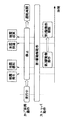
- FIG. 14 is a hardware configuration diagram of a main part of the displacement suppressing device 18 according to the first embodiment.
- the processing circuit includes at least one processor 100a and at least one memory 100b.
- the processing circuit may include at least one dedicated hardware 200 with or as a substitute for the processor 100a and the memory 100b.
- each function of the displacement suppressing device 18 is realized by software, firmware, or a combination of software and firmware. At least one of the software and firmware is written as a program. The program is stored in the memory 100b. The processor 100a realizes each function of the displacement suppressing device 18 by reading and executing the program stored in the memory 100b.
- the processor 100a is also referred to as a CPU (Central Processing Unit), a processing device, an arithmetic unit, a microprocessor, a microcomputer, and a DSP.
- the memory 100b is composed of, for example, a non-volatile or volatile semiconductor memory such as a RAM, a ROM, a flash memory, an EPROM, or an EEPROM.
- the processing circuit includes the dedicated hardware 200
- the processing circuit is realized by, for example, a single circuit, a composite circuit, a programmed processor, a parallel programmed processor, an ASIC, an FPGA, or a combination thereof.
- Each function of the displacement suppression device 18 can be realized by a processing circuit. Alternatively, each function of the displacement suppressing device 18 can be collectively realized by a processing circuit. For each function of the displacement suppression device 18, a part may be realized by the dedicated hardware 200, and the other part may be realized by software or firmware. As described above, the processing circuit realizes each function of the displacement suppressing device 18 by the dedicated hardware 200, software, firmware, or a combination thereof.
- Embodiment 2 The differences between the second embodiment and the examples disclosed in the first embodiment will be described in particular detail. As for the features not described in the second embodiment, any of the features disclosed in the first embodiment may be adopted.
- the first drive unit 27 moves the stopper 26 to a relative position corresponding to the stop position in advance, so that the occurrence of an earthquake is detected.
- the effect of suppressing the displacement of the car 8 is exhibited more quickly.
- a configuration in which the first drive unit 27 moves the stopper 26 in the normal operation will be described.
- FIG. 15 is a flow chart showing an example of the operation of the elevator 1 according to the second embodiment.
- control panel 15 calculates the floor on which the traveling car 8 will stop next, for example, based on the call information to be made to respond to the car 8.
- the control unit 23 of the displacement suppression device 18 acquires the position of the restraint unit 13 closest to the stop position where the car 8 stops by referring to the storage unit 24.
- the control unit 23 calculates the relative position of the restraint unit 13 with respect to the car 8 stopped at the stop position.
- the command unit 25 of the control unit 23 outputs a command signal to the first drive unit 27 based on the calculated relative position and the like. Further, the command unit of the control unit 23 outputs a command signal to the second drive unit 28 when the occurrence of an earthquake is detected by the earthquake detector 14.
- FIG. 16 is a diagram showing an example of the operation timing of the elevator 1 according to the second embodiment.
- FIG. 16 shows an example of the operation of the elevator 1 when an earthquake occurs after the car 8 is stopped.
- the command unit 25 outputs a command signal to the first drive unit 27 when the deceleration of the car 8 is started so that the control panel 15 stops at the stop position in normal operation.
- the first drive unit 27 moves the stopper 26 in the vertical direction to the relative position of the restraint unit 13 calculated by the control unit 23 as an operation based on the command signal from the command unit 25. After that, the car 8 stops at the stop position. At this time, the stopper 26 is moved to the relative position calculated by the control unit 23 by the first drive unit 27.
- the earthquake detector 14 detects the occurrence of an earthquake after the occurrence of an earthquake.
- the earthquake detector 14 outputs a signal indicating the detection of an earthquake to the control panel 15.
- the control panel 15 shifts the operation mode to the seismic control operation.
- the command unit 25 outputs a command signal to the second drive unit 28.
- the second drive unit 28 moves the stopper 26 so as to narrow the gap between the car guide rail 10 and the stopper 26 as an operation based on the command signal from the command unit 25.
- the gap between the stopper 26 and the restraint portion 13 is narrowed. Therefore, even when a horizontal seismic load or the like is applied to the car 8 through the car guide rail 10, the displacement of the car 8 is suppressed. Further, since the car guide rail 10 receives a reaction force from the car 8 at the restraint portion 13 in which the displacement in the horizontal direction is restrained, the car guide rail 10 is less likely to bend due to the reaction force from the car 8.
- the control unit 23 outputs a command signal for canceling the operation to the first drive unit 27 and the second drive unit 28.
- the first drive unit 27 of the displacement suppression device 18 faces any restraint unit 13 when the elevating body stops at any stop position in normal operation. Move the stopper 26 to the relative position.
- the first drive unit 27 moves the stopper 26 to a relative position corresponding to the stop position in advance. As a result, the effect of suppressing the displacement of the elevating body when the occurrence of an earthquake is detected is exerted more quickly.
- the first drive unit 27 may start the movement of the stopper 26 before the elevating body decelerates. Alternatively, the first drive unit 27 may start the movement of the stopper 26 after the elevating body has stopped.
- Embodiment 3 The differences between the third embodiment and the examples disclosed in the first embodiment or the second embodiment will be described in particular detail. As for the features not described in the third embodiment, any of the features disclosed in the first embodiment or the second embodiment may be adopted.
- the first drive unit 27 Even when the car 8 is running, the stop position for stopping the car 8 in the event of an earthquake, the position of the restraint portion 13 closest to the stop position, and the relative position of the restraint portion 13 with respect to the car 8 are , Can be calculated before an earthquake occurs. Therefore, even in normal operation, the first drive unit 27 always moves the stopper 26 to a relative position corresponding to the stop position in advance, which has the effect of suppressing the displacement of the car 8 when the occurrence of an earthquake is detected. It will be exerted more quickly. In the third embodiment, the configuration in which the first drive unit 27 constantly moves the stopper 26 in the normal operation will be described.
- FIG. 17 is a diagram showing an example of the operation timing of the elevator 1 according to the third embodiment.
- control panel 15 calculates the nearest floor to stop the car 8 if an earthquake occurs, for example, based on the position and speed of the car 8.
- the control unit 23 of the displacement suppression device 18 acquires the position of the restraint unit 13 closest to the stop position where the car 8 stops by referring to the storage unit 24.
- the control unit 23 calculates the relative position of the restraint unit 13 with respect to the car 8 stopped at the stop position. For example, when the calculated relative position changes, the command unit 25 of the control unit 23 outputs a command signal to the first drive unit 27.
- the command unit 25 constantly outputs a command signal to the first drive unit 27 regardless of whether or not the occurrence of an earthquake is detected.
- the first drive unit 27 moves the stopper 26 in the vertical direction to the relative position of the restraint unit 13 calculated by the control unit 23 as an operation based on the command signal from the command unit 25.
- the earthquake detector 14 detects the occurrence of an earthquake after it has occurred.
- the earthquake detector 14 outputs a signal indicating the detection of an earthquake to the control panel 15.
- the control panel 15 shifts the operation mode to the seismic control operation.
- the command unit 25 outputs a command signal to the second drive unit 28.
- the second drive unit 28 moves the stopper 26 so as to narrow the gap between the car guide rail 10 and the stopper 26 as an operation based on the command signal from the command unit 25.
- the gap between the stopper 26 and the restraint portion 13 is narrowed. Therefore, even when a horizontal seismic load or the like is applied to the car 8 through the car guide rail 10, the displacement of the car 8 is suppressed. Further, since the car guide rail 10 receives a reaction force from the car 8 at the restraint portion 13 in which the displacement in the horizontal direction is restrained, the car guide rail 10 is less likely to bend due to the reaction force from the car 8.
- the control unit 23 outputs a command signal for canceling the operation to the second drive unit 28.
- the first drive unit 27 of the displacement suppressing device 18 is set to a relative position corresponding to the current position of the elevating body when the elevating body is traveling in normal operation.
- the relative position for moving the stopper 26 is such that when the elevating body stops from the current position, the movement distance of the stopper 26 to the relative position facing the nearest restraint portion 13 among the plurality of restraint portions 13 is the smallest. Relative position.
- the first drive unit 27 always moves the stopper 26 in advance to a relative position corresponding to the current position of the elevating body even in normal operation.
- the effect of suppressing the displacement of the elevating body when the occurrence of an earthquake is detected is exerted more quickly.
- the displacement of the elevating body is suppressed more effectively.
- Embodiment 4 In the fourth embodiment, the differences from the examples disclosed in the first to third embodiments will be described in particular detail. As for the features not described in the fourth embodiment, any of the features disclosed in the first to third embodiments may be adopted.
- the gap between the car guide rail 10 and the stopper 26 is narrowed even in normal operation, the effect of suppressing the displacement of the car 8 when the occurrence of an earthquake is detected is exhibited more quickly.
- the stopper 26 comes into contact with the car guide rail 10, the running of the car 8 may be hindered.
- the gap can be adjusted so that the running of the car 8 is not hindered.
- a configuration for measuring and adjusting the gap between the car guide rail 10 and the stopper 26 will be described.
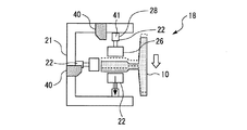
- FIG 18 and 19 are top views of the stopper unit 22 according to the fourth embodiment.
- the displacement suppressing device 18 includes a measuring unit 40.
- the measuring unit 40 is a portion that measures the gap between the car guide rail 10 and the stopper 26.
- the measuring unit 40 includes a sensor for measuring the gap in the front-rear direction and a sensor for measuring the gap in the left-right direction. Based on the measurement result of the gap between one surface of the front surface or the rear surface of the car guide rail 10 and the stopper 26 facing the surface, the measuring unit 40 has the other surface and the surface of the front surface or the rear surface of the car guide rail 10. The gap between the stopper 26 and the stopper 26 may be calculated.
- the measuring unit 40 measures the gap by, for example, a non-contact type distance sensor.
- the measuring unit 40 may be provided with individual sensors corresponding to one-to-one in each stopper unit 22.
- the storage unit 24 of the control unit 23 stores the first threshold value and the second threshold value.
- the first threshold value is a threshold value preset with respect to the gap between the car guide rail 10 and the stopper 26 so as to prevent contact between the car guide rail 10 and the stopper 26.
- the second threshold value is a threshold value preset with respect to the gap between the car guide rail 10 and the stopper 26 so as to suppress the displacement of the car 8.
- the value of the second threshold value is equal to or higher than the value of the first threshold value.
- the second drive unit 28 has an actuator 41 that directly moves the stopper 26 in the horizontal direction.
- the gap between the car guide rail 10 and the stopper 26 is adjusted by, for example, the actuator 41 of the second drive unit 28.
- the configuration of the second drive unit 28 may be the same as the configuration shown in the first embodiment or the like.
- the gap between the car guide rail 10 and the stopper 26 is narrowed by the second drive unit 28.
- the gap between the car guide rail 10 and the stopper 26 may fluctuate due to vibration or the like accompanying the running of the car 8.
- the second driving unit 28 widens the gap between the car guide rail 10 and the stopper 26 by, for example, an actuator 41.
- the second driving unit 28 narrows the gap between the car guide rail 10 and the stopper 26 by, for example, an actuator 41.
- the gap between the car guide rail 10 and the stopper 26 that can suppress the displacement of the car 8 is maintained in normal operation.
- the second drive unit 28 keeps the gap between the guide rail and the stopper 26 narrow in the car 8 regardless of the measurement by the measurement unit 40. As a result, the displacement of the car 8 due to the shaking of the earthquake or the like is suppressed through the car guide rail 10.
- the displacement suppressing device 18 includes a measuring unit 40.
- the measuring unit 40 measures the gap between the guide rail and the stopper 26.
- the second drive unit 28 widens the gap between the guide rail and the stopper 26 when the gap measured by the measurement unit 40 is smaller than the preset first threshold value in normal operation.
- the second drive unit 28 determines the position of the stopper 26 in a state where the gap with the guide rail is narrowed regardless of the size of the gap measured by the measurement unit 40. maintain.
- the gap is adjusted in normal operation so that the traveling of the elevating body is not hindered based on the measurement result of the gap between the guide rail and the stopper 26.
- the gap between the guide rail and the stopper 26 can be narrowed in advance even in normal operation. Therefore, the effect of suppressing the displacement of the elevating body when the occurrence of an earthquake is detected is exhibited more quickly.
- the displacement suppression device according to the present disclosure can be applied to an elevator body.
Abstract
Provided is an elevator ascending/descending body displacement suppression device which makes it unlikely for a guide rail to warp due to the counterforce received from the ascending/descending body. A stopper unit (22) of this displacement suppression device (18) is provided to the ascending/descending body. The stopper unit (22) is provided with a stopper (26), a first drive unit (27) and a second drive unit (28). The stopper (26) faces a guide rail for guiding the ascending/descending body. The first drive unit (27) moves the position of the stopper (26) relative to the ascending/descending body in the direction in which the ascending/descending body travels. The first drive unit (27) causes the stopper (26) to face the guide rail restricting part (13). The second drive unit (28) changes the gap between the guide rail and the stopper (26) by moving the stopper (26). The second drive unit (28) suppresses displacement of the ascending/descending body via the stopper (26) which is separated from the guide rail restricting part (13) by a narrower gap.
Description
本開示は、エレベーターの昇降体の変位抑制装置に関する。
This disclosure relates to a displacement suppressing device for an elevator elevator.
特許文献1は、エレベーターの例を開示する。エレベーターにおいて、かごに地震プレートが設けられる。地震プレートは、ガイドレールと協働してかごの横方向の変位を抑制する。
Patent Document 1 discloses an example of an elevator. In the elevator, a seismic plate is installed in the car. The seismic plate works with the guide rails to reduce lateral displacement of the car.
しかしながら、特許文献1のエレベーターにおいて、かごなどの昇降体から受ける反力によってガイドレールがたわむ場合がある。
However, in the elevator of Patent Document 1, the guide rail may bend due to the reaction force received from the elevating body such as a car.
本開示は、このような課題の解決に係るものである。本開示は、昇降体から受ける反力によってガイドレールがたわみにくいエレベーターの昇降体の変位抑制装置を提供する。
This disclosure relates to the solution of such problems. The present disclosure provides a displacement suppressing device for an elevator elevator whose guide rail is less likely to bend due to a reaction force received from the elevator.
本開示に係るエレベーターの昇降体の変位抑制装置は、複数の拘束部を有するガイドレールに沿って走行し通常運転において複数の停止位置のいずれかに停止するエレベーターの昇降体に設けられるストッパユニットを備え、ストッパユニットは、ガイドレールに対向するストッパと、昇降体に対するストッパの相対位置を昇降体の走行方向に移動させ、ストッパを複数の拘束部のいずれかに対向させる第1駆動部と、ストッパを移動させることでガイドレールおよびストッパの隙間を変化させ、複数の拘束部のいずれかとの隙間を狭めたストッパによって昇降体の変位を抑制する第2駆動部と、を備える。
The displacement suppressing device for an elevator elevating body according to the present disclosure includes a stopper unit provided on the elevator elevating body that travels along a guide rail having a plurality of restraining portions and stops at one of a plurality of stop positions in normal operation. The stopper unit includes a stopper facing the guide rail, a first drive unit that moves the relative position of the stopper with respect to the elevating body in the traveling direction of the elevating body, and makes the stopper face any of a plurality of restraining parts, and a stopper. A second drive unit is provided, which changes the gap between the guide rail and the stopper by moving the guide rail and suppresses the displacement of the elevating body by a stopper that narrows the gap between the guide rail and the stopper.
本開示に係る変位抑制装置であれば、昇降体から受ける反力によってガイドレールがたわみにくくなる。
With the displacement suppressing device according to the present disclosure, the guide rail is less likely to bend due to the reaction force received from the elevating body.
本開示を実施するための形態について添付の図面を参照しながら説明する。各図において、同一または相当する部分には同一の符号を付して、重複する説明は適宜に簡略化または省略する。
The mode for implementing this disclosure will be explained with reference to the attached drawings. In each figure, the same or corresponding parts are designated by the same reference numerals, and duplicate description will be appropriately simplified or omitted.
実施の形態1.
図1は、実施の形態1に係るエレベーター1の構成図である。Embodiment 1.
FIG. 1 is a configuration diagram of anelevator 1 according to the first embodiment.
図1は、実施の形態1に係るエレベーター1の構成図である。
FIG. 1 is a configuration diagram of an
エレベーター1は、複数の階床を有する建物2に設けられる。建物2において、昇降路3が設けられる。昇降路3は、複数の階床にわたる空間である。建物2において、昇降路3の上部に機械室4が設けられる。建物2において、昇降路3の底部にピット5が設けられる。
The elevator 1 is installed in a building 2 having a plurality of floors. A hoistway 3 is provided in the building 2. The hoistway 3 is a space that spans a plurality of floors. In the building 2, the machine room 4 is provided above the hoistway 3. In the building 2, a pit 5 is provided at the bottom of the hoistway 3.
エレベーター1は、巻上機6と、主ロープ7と、かご8と、釣合い錘9と、を備える。
Elevator 1 includes a hoist 6, a main rope 7, a basket 8, and a counterweight 9.
巻上機6は、シーブおよびモータを備える。巻上機6のモータは、巻上機6のシーブを回転駆動する装置である。巻上機6は、例えば機械室4に設けられる。
The hoisting machine 6 includes a sheave and a motor. The motor of the hoisting machine 6 is a device for rotating and driving the sheave of the hoisting machine 6. The hoisting machine 6 is provided in, for example, the machine room 4.
主ロープ7は、巻上機6のシーブに巻き掛けられる。主ロープ7の一端は、かご8に接続される。主ロープ7の他端は、釣合い錘9に接続される。エレベーター1は、複数の主ロープ7を備えていてもよい。
The main rope 7 is wound around the sheave of the hoist 6. One end of the main rope 7 is connected to the car 8. The other end of the main rope 7 is connected to the counterweight 9. The elevator 1 may include a plurality of main ropes 7.
かご8は、昇降路3において鉛直方向に走行することで複数の階床の間で利用者などを輸送する装置である。釣合い錘9は、主ロープ7を通じて巻上機6のシーブの両側にかかる荷重のバランスをかご8との間でとる装置である。かご8および釣合い錘9は、主ロープ7によって昇降路3において吊られる。かご8および釣合い錘9は、巻上機6が主ロープ7を巻き上げることによって昇降路3を互いに反対方向に走行する。かご8および釣合い錘9の各々は、昇降体の例である。
The car 8 is a device for transporting a user or the like between a plurality of floors by traveling in the vertical direction on the hoistway 3. The counterweight 9 is a device that balances the load applied to both sides of the sheave of the hoist 6 through the main rope 7 with the car 8. The car 8 and the counterweight 9 are suspended in the hoistway 3 by the main rope 7. The car 8 and the counterweight 9 travel on the hoistway 3 in opposite directions by the hoisting machine 6 winding up the main rope 7. Each of the cage 8 and the counterweight 9 is an example of an elevating body.
昇降路3において、一対のかごガイドレール10、一対の釣合い錘ガイドレール11、および複数のブラケット12が設けられる。
In the hoistway 3, a pair of car guide rails 10, a pair of counterweight guide rails 11, and a plurality of brackets 12 are provided.
一対のかごガイドレール10は、昇降路3におけるかご8の走行を案内する一対のガイドレールである。各々のかごガイドレール10は、昇降路3において鉛直方向に沿って配置される。一方のかごガイドレール10は、かご8の左側に配置される。他方のかごガイドレール10は、かご8の右側に配置される。
The pair of car guide rails 10 is a pair of guide rails that guide the traveling of the car 8 on the hoistway 3. Each car guide rail 10 is arranged along the vertical direction in the hoistway 3. One car guide rail 10 is arranged on the left side of the car 8. The other car guide rail 10 is arranged on the right side of the car 8.
一対の釣合い錘ガイドレール11は、昇降路3における釣合い錘9の走行を案内する一対のガイドレールである。各々の釣合い錘ガイドレール11は、昇降路3において鉛直方向に沿って配置される。一方の釣合い錘ガイドレール11は、釣合い錘9の左側に配置される。他方の釣合い錘ガイドレール11は、釣合い錘9の右側に配置される。
The pair of counterweight guide rails 11 is a pair of guide rails that guide the traveling of the counterweight 9 on the hoistway 3. Each counterweight guide rail 11 is arranged along the vertical direction in the hoistway 3. One of the counterweight guide rails 11 is arranged on the left side of the counterweight 9. The other counterbalance weight guide rail 11 is arranged on the right side of the counterbalance weight 9.
かご8または釣合い錘9などの昇降体は、かごガイドレール10または釣合い錘ガイドレール11などのガイドレールに沿って鉛直方向に走行する。昇降体の走行を案内するガイドレールの各々は、複数のブラケット12によって昇降路3に固定される。各々のガイドレールは、複数の拘束部13を有する。各々の拘束部13は、ガイドレールの水平方向の変位が拘束される部分である。拘束部13は、例えばガイドレールにおいてブラケット12によって固定される部分などである。昇降路3における鉛直方向のブラケット12の間隔は、例えばかご8の高さより短い。あるいは、各々のブラケット12は、昇降体の停止位置のいずれかに対応して配置されてもよい。
The elevating body such as the car 8 or the counterweight 9 travels in the vertical direction along the guide rail such as the car guide rail 10 or the counterweight guide rail 11. Each of the guide rails that guide the traveling of the elevating body is fixed to the hoistway 3 by the plurality of brackets 12. Each guide rail has a plurality of restraint portions 13. Each restraint portion 13 is a portion where the horizontal displacement of the guide rail is constrained. The restraint portion 13 is, for example, a portion fixed by the bracket 12 on the guide rail. The distance between the brackets 12 in the vertical direction in the hoistway 3 is shorter than, for example, the height of the car 8. Alternatively, each bracket 12 may be arranged corresponding to any of the stop positions of the elevating body.
エレベーター1は、地震感知器14と、制御盤15と、を備える。
Elevator 1 includes an earthquake detector 14 and a control panel 15.
地震感知器14は、地震の発生を感知する部分である。地震感知器14は、例えばピット5に設けられる。このとき、地震感知器14は、例えばP波(Primary wave)によって地震を感知するP波感知器である。あるいは、地震感知器14は、例えば機械室4に設けられる。このとき、地震感知器14は、例えばS波(Secondary wave)によって地震を感知するS波感知器である。地震感知器14は、ピット5および機械室4の両方に設けられていてもよい。
The earthquake detector 14 is a part that detects the occurrence of an earthquake. The seismic detector 14 is provided, for example, in the pit 5. At this time, the seismic detector 14 is a P wave detector that detects an earthquake by, for example, a P wave (Primary wave). Alternatively, the seismic detector 14 is provided, for example, in the machine room 4. At this time, the earthquake detector 14 is an S wave detector that detects an earthquake by, for example, an S wave (Secondary wave). The seismic detector 14 may be provided in both the pit 5 and the machine room 4.
制御盤15は、エレベーター1の動作を制御する装置である。制御盤15は、例えば機械室4に設けられる。制御盤15は、例えば巻上機6の動作の制御によってかご8および釣合い錘9の走行を制御する。また、制御盤15は、エレベーター1の運転モードを管理する。エレベーター1の運転モードは、通常運転と、地震時管制運転と、を含む。通常運転は、利用者によって登録された呼びなどに応答させるようにかご8を走行させる運転モードである。通常運転において、かご8は複数の階床のいずれかに停止する。各々の階床の位置は、かご8についての通常運転における停止位置の例である。また、かご8がいずれかの階床に停止するときに、釣合い錘9は、当該階床に対応する位置に停止する。各々の階床に対応して釣合い錘9が停止する位置は、釣合い錘9についての通常運転における停止位置の例である。地震時管制運転は、エレベーター1において例えば地震感知器14などによって地震の発生が感知されたときの運転モードである。地震時管制運転において、制御盤15は、例えば走行しているかご8を最寄りの階床に停止させる。なお、エレベーター1における地震の発生の感知は、例えば緊急地震速報などのエレベーター1の外部から提供される地震発生の予報または警報などの情報に基づいて行われてもよい。あるいは、エレベーター1における地震の発生の感知は、例えば建物2より震源に近い建物に設けられた地震感知器による地震感知の信号を受信することなどによって行われてもよい。
The control panel 15 is a device that controls the operation of the elevator 1. The control panel 15 is provided in, for example, the machine room 4. The control panel 15 controls the traveling of the car 8 and the counterweight 9 by, for example, controlling the operation of the hoisting machine 6. Further, the control panel 15 manages the operation mode of the elevator 1. The operation mode of the elevator 1 includes normal operation and seismic control operation. The normal operation is an operation mode in which the car 8 is driven so as to answer a call or the like registered by the user. In normal operation, the car 8 stops at one of a plurality of floors. The position of each floor is an example of the stop position in normal operation for the car 8. Further, when the car 8 stops on any floor, the counterweight 9 stops at a position corresponding to the floor. The position where the counterweight 9 stops corresponding to each floor is an example of the stop position in the normal operation of the counterweight 9. The earthquake control operation is an operation mode when the occurrence of an earthquake is detected in the elevator 1 by, for example, an earthquake detector 14. In earthquake control operation, the control panel 15 stops, for example, the traveling car 8 on the nearest floor. The detection of the occurrence of an earthquake in the elevator 1 may be performed based on information such as an earthquake occurrence forecast or warning provided from the outside of the elevator 1 such as an Earthquake Early Warning. Alternatively, the detection of the occurrence of an earthquake in the elevator 1 may be performed, for example, by receiving a signal for seismic detection by an earthquake detector provided in a building closer to the epicenter than the building 2.
図2は、実施の形態1に係るかご8の正面図である。
FIG. 2 is a front view of the car 8 according to the first embodiment.
かご8は、かご枠16と、複数のガイドシュー17と、変位抑制装置18と、を備える。
The car 8 includes a car frame 16, a plurality of guide shoes 17, and a displacement suppressing device 18.
かご枠16は、上梁19と、下梁20と、一対の縦柱21と、を備える。上梁19は、かご8の上部において左端部および右端部の間にわたって配置される部材である。例えば上梁19において、主ロープ7が取り付けられる。下梁20は、かご8の下部において左端部および右端部の間にわたって配置される部材である。一対の縦柱21は、上梁19および下梁20の間にわたって配置される部材である。一方の縦柱21は、かご8の左端部に配置される。他方の縦柱21は、かご8の右端部に配置される。左側の縦柱21は、かご8の左側のかごガイドレール10に沿って配置される。右側の縦柱21は、かご8の右側のかごガイドレール10に沿って配置される。
The car frame 16 includes an upper beam 19, a lower beam 20, and a pair of vertical columns 21. The upper beam 19 is a member arranged between the left end portion and the right end portion in the upper part of the car 8. For example, in the upper beam 19, the main rope 7 is attached. The lower beam 20 is a member arranged between the left end portion and the right end portion in the lower part of the car 8. The pair of vertical columns 21 are members arranged between the upper beam 19 and the lower beam 20. One vertical pillar 21 is arranged at the left end of the car 8. The other vertical pillar 21 is arranged at the right end of the car 8. The left vertical pillar 21 is arranged along the left car guide rail 10 of the car 8. The vertical pillar 21 on the right side is arranged along the car guide rail 10 on the right side of the car 8.
複数のガイドシュー17は、一対のかごガイドレール10によって案内される部分である。各々のガイドシュー17は、いずれかのかごガイドレール10に対向する。各々のガイドシュー17は、例えばかご枠16に取り付けられる。各々のガイドシュー17は、例えば上梁19または下梁20の左端部または右端部などに配置される。
The plurality of guide shoes 17 are portions guided by a pair of car guide rails 10. Each guide shoe 17 faces one of the car guide rails 10. Each guide shoe 17 is attached to, for example, a car frame 16. Each guide shoe 17 is arranged, for example, at the left end portion or the right end portion of the upper beam 19 or the lower beam 20.
変位抑制装置18は、かご8などの昇降体の水平方向の変位を抑制する装置である。変位抑制装置18は、複数のストッパユニット22と、制御部23と、を備える。
The displacement suppressing device 18 is a device that suppresses the horizontal displacement of an elevating body such as a car 8. The displacement suppressing device 18 includes a plurality of stopper units 22 and a control unit 23.
各々のストッパユニット22は、かごガイドレール10によってかご8の変位を規制する部分である。各々のストッパユニット22は、例えばいずれかの縦柱21の上部または下部に取り付けられる。
Each stopper unit 22 is a portion that regulates the displacement of the car 8 by the car guide rail 10. Each stopper unit 22 is attached to, for example, the upper part or the lower part of any of the vertical columns 21.
制御部23は、各々のストッパユニット22の動作を制御する部分である。制御部23は、例えばエレベーター1の制御盤15に搭載される。あるいは、制御部23は、例えばかご8の上部などに設けられていてもよい。あるいは、変位抑制装置18は、各々のストッパユニット22に1対1に対応する個別の制御部23を備えていてもよい。制御部23は、記憶部24と、指令部25と、を備える。記憶部24は、情報を記憶する部分である。記憶部24において、例えばかごガイドレール10における複数の拘束部13の位置が記憶される。指令部25は、入力される情報および記憶部24が記憶している情報などに基づいて、各々のストッパユニット22に指令信号を出力する部分である。
The control unit 23 is a part that controls the operation of each stopper unit 22. The control unit 23 is mounted on, for example, the control panel 15 of the elevator 1. Alternatively, the control unit 23 may be provided, for example, on the upper part of the car 8. Alternatively, the displacement suppressing device 18 may be provided with individual control units 23 corresponding to one-to-one in each stopper unit 22. The control unit 23 includes a storage unit 24 and a command unit 25. The storage unit 24 is a portion that stores information. In the storage unit 24, for example, the positions of the plurality of restraint units 13 on the car guide rail 10 are stored. The command unit 25 is a unit that outputs a command signal to each stopper unit 22 based on the input information, the information stored in the storage unit 24, and the like.
図3は、実施の形態1に係るストッパユニット22の上面図である。
図3において、図2におけるA-A断面図が示される。 FIG. 3 is a top view of thestopper unit 22 according to the first embodiment.
FIG. 3 shows a cross-sectional view taken along the line AA in FIG.
図3において、図2におけるA-A断面図が示される。 FIG. 3 is a top view of the
FIG. 3 shows a cross-sectional view taken along the line AA in FIG.
この例において、各々の縦柱21の上部に3つのストッパユニット22が取り付けられる。また、各々の縦柱21の下部にも同様に3つのストッパユニット22が設けられる。図3において、上部の3つのストッパユニット22が示される。各々のストッパユニット22は、互いに独立に動作する。
In this example, three stopper units 22 are attached to the upper part of each vertical pillar 21. Further, three stopper units 22 are similarly provided at the lower part of each vertical pillar 21. In FIG. 3, the upper three stopper units 22 are shown. Each stopper unit 22 operates independently of each other.
各々のストッパユニット22は、ストッパ26を備える。ストッパ26は、かごガイドレール10の表面に対向する部材である。3つのストッパユニット22の1つにおいて、ストッパ26はかごガイドレール10の前面に対向する。3つのストッパユニット22の他の1つにおいて、ストッパ26はかごガイドレール10の後面に対向する。3つのストッパユニット22の残りの1つにおいて、ストッパ26はかごガイドレール10の左右の内側の側面に対向する。ここで、左右の内側の側面は、かご8側の側面である。
Each stopper unit 22 includes a stopper 26. The stopper 26 is a member facing the surface of the car guide rail 10. In one of the three stopper units 22, the stopper 26 faces the front surface of the car guide rail 10. In the other one of the three stopper units 22, the stopper 26 faces the rear surface of the car guide rail 10. In the remaining one of the three stopper units 22, the stopper 26 faces the left and right inner side surfaces of the car guide rail 10. Here, the left and right inner side surfaces are the side surfaces on the car 8 side.
図4は、実施の形態1に係るストッパユニット22の側面図である。
図4において、図3におけるB-B断面図が示される。 FIG. 4 is a side view of thestopper unit 22 according to the first embodiment.
FIG. 4 shows a sectional view taken along the line BB in FIG.
図4において、図3におけるB-B断面図が示される。 FIG. 4 is a side view of the
FIG. 4 shows a sectional view taken along the line BB in FIG.
各々のストッパユニット22は、第1駆動部27と、第2駆動部28と、を備える。
Each stopper unit 22 includes a first drive unit 27 and a second drive unit 28.
第1駆動部27は、かご8に対するストッパ26の相対位置を鉛直方向に移動させる部分である。第2駆動部28は、ストッパ26を移動させることでかごガイドレール10およびストッパ26の隙間を変化させる部分である。
The first drive unit 27 is a portion that moves the relative position of the stopper 26 with respect to the car 8 in the vertical direction. The second drive unit 28 is a portion that changes the gap between the car guide rail 10 and the stopper 26 by moving the stopper 26.
第2駆動部28は、フレーム29を備える。フレーム29は、ストッパ26を保持する部分である。フレーム29において、鉛直方向に向けてネジ穴30が設けられる。
The second drive unit 28 includes a frame 29. The frame 29 is a portion that holds the stopper 26. In the frame 29, a screw hole 30 is provided in the vertical direction.
第1駆動部27は、一対の軸受31と、ガイドシャフト32と、駆動モータ33と、ボールネジ34と、を備える。一対の軸受31は、第1駆動部27によるストッパ26の相対位置の移動範囲の上方および下方に配置される。ガイドシャフト32は、一対の軸受31の間において縦柱21に平行に配置される。第1駆動部27は、互いに平行なガイドシャフト32を複数備えてもよい。駆動モータ33は、一方の軸受31に取り付けられる。ボールネジ34は、他方の軸受31および駆動モータ33の間においてガイドシャフト32に平行に配置される。ボールネジ34は、第2駆動部28のフレーム29のネジ穴30に通される。第1駆動部27は、制御部23の制御に基づいて駆動モータ33によってボールネジ34を回転させることで、ストッパ26を第2駆動部28とともに鉛直方向に移動させる。なお、第1駆動部27は、他の方法によってストッパ26の相対位置を鉛直方向に移動させてもよい。例えば、第1駆動部27は、フレーム29などを鉛直方向に移動させるリニアモータ、または油圧もしくは空圧のシリンダなどを有していてもよい。
The first drive unit 27 includes a pair of bearings 31, a guide shaft 32, a drive motor 33, and a ball screw 34. The pair of bearings 31 are arranged above and below the range of movement of the relative position of the stopper 26 by the first drive unit 27. The guide shaft 32 is arranged parallel to the vertical column 21 between the pair of bearings 31. The first drive unit 27 may include a plurality of guide shafts 32 parallel to each other. The drive motor 33 is attached to one of the bearings 31. The ball screw 34 is arranged parallel to the guide shaft 32 between the other bearing 31 and the drive motor 33. The ball screw 34 is passed through the screw hole 30 of the frame 29 of the second drive unit 28. The first drive unit 27 rotates the ball screw 34 by the drive motor 33 based on the control of the control unit 23, so that the stopper 26 is moved in the vertical direction together with the second drive unit 28. The first drive unit 27 may move the relative position of the stopper 26 in the vertical direction by another method. For example, the first drive unit 27 may have a linear motor for moving the frame 29 or the like in the vertical direction, a hydraulic or pneumatic cylinder, or the like.
図5は、実施の形態1に係るストッパユニット22の構成図である。
図5において、第2駆動部28の内部の構造を側方から見た図が示される。 FIG. 5 is a configuration diagram of thestopper unit 22 according to the first embodiment.
FIG. 5 shows a side view of the internal structure of thesecond drive unit 28.
図5において、第2駆動部28の内部の構造を側方から見た図が示される。 FIG. 5 is a configuration diagram of the
FIG. 5 shows a side view of the internal structure of the
ストッパ26は、かごガイドレール10の表面に平行な鉛直面で当該表面に対向する。ストッパ26は、かごガイドレール10の反対側に鉛直面および第1斜面35を有する。第1斜面35は、かごガイドレール10の表面に対して傾く面である。第1斜面35は、例えば下方に傾く面である。第1斜面35は、かごガイドレール10の反対側の鉛直面の下方に設けられる。ストッパ26は、フレーム29の案内によってかごガイドレール10との隙間を変化させうるように移動可能に保持される。ストッパ26は、かごガイドレール10から離れるときに下方に移動するように案内される。図5において、ストッパ26およびかごガイドレール10の隙間が拡げられた状態の図が示される。
The stopper 26 faces the surface of the car guide rail 10 with a vertical surface parallel to the surface of the car guide rail 10. The stopper 26 has a vertical surface and a first slope 35 on the opposite side of the car guide rail 10. The first slope 35 is a surface that is inclined with respect to the surface of the car guide rail 10. The first slope 35 is, for example, a surface inclined downward. The first slope 35 is provided below the vertical surface on the opposite side of the car guide rail 10. The stopper 26 is movably held so that the gap between the stopper 26 and the car guide rail 10 can be changed by the guidance of the frame 29. The stopper 26 is guided to move downward when it leaves the car guide rail 10. FIG. 5 shows a state in which the gap between the stopper 26 and the car guide rail 10 is widened.
第2駆動部28は、移動片36と、押上バネ37と、アクチュエータ38と、を備える。移動片36は、フレーム29の案内によって鉛直方向に移動可能に保持される部分である。移動片36は、上端部に第2斜面39を有する。第2斜面39は、第1斜面35に平行な面である。かごガイドレール10およびストッパ26の隙間が拡げられた状態において、第2斜面39は第1斜面35に接触する。移動片36は、第2斜面39のストッパ26側から下方に下がる鉛直面を有する。押上バネ37は、移動片36の下端に接触して配置される。押上バネ37の中心軸は、鉛直方向に向けられる。かごガイドレール10およびストッパ26の隙間が拡げられた状態において、押上バネ37は圧縮されている。アクチュエータ38は、制御部23の制御に基づいて移動片36を鉛直方向に移動させることでかごガイドレール10およびストッパ26の隙間を変化させる部分である。
The second drive unit 28 includes a moving piece 36, a push-up spring 37, and an actuator 38. The moving piece 36 is a portion that is movably held in the vertical direction by the guidance of the frame 29. The moving piece 36 has a second slope 39 at the upper end thereof. The second slope 39 is a plane parallel to the first slope 35. The second slope 39 comes into contact with the first slope 35 in a state where the gap between the car guide rail 10 and the stopper 26 is widened. The moving piece 36 has a vertical surface that descends downward from the stopper 26 side of the second slope 39. The push-up spring 37 is arranged in contact with the lower end of the moving piece 36. The central axis of the push-up spring 37 is oriented in the vertical direction. The push-up spring 37 is compressed in a state where the gap between the car guide rail 10 and the stopper 26 is widened. The actuator 38 is a portion that changes the gap between the car guide rail 10 and the stopper 26 by moving the moving piece 36 in the vertical direction based on the control of the control unit 23.
かごガイドレール10およびストッパ26の隙間を拡げるときに、アクチュエータ38は、押上バネ37の弾性力に抗しながら移動片36を鉛直方向に押し下げる。移動片36の移動によって、フレーム29の内部においてストッパ26のかごガイドレール10の反対側に空間が生じる。ストッパ26は、例えば自重などによってかごガイドレール10から離れる方向に移動する。あるいは、ストッパ26および移動片36またはフレーム29に磁石などを設けることによって、磁力によってストッパ26をかごガイドレール10から離れる方向に移動させてもよい。
When expanding the gap between the car guide rail 10 and the stopper 26, the actuator 38 pushes down the moving piece 36 in the vertical direction while resisting the elastic force of the push-up spring 37. The movement of the moving piece 36 creates a space inside the frame 29 on the opposite side of the car guide rail 10 of the stopper 26. The stopper 26 moves in a direction away from the car guide rail 10 due to, for example, its own weight. Alternatively, the stopper 26 may be moved in a direction away from the car guide rail 10 by magnetic force by providing a magnet or the like on the stopper 26 and the moving piece 36 or the frame 29.
図6は、実施の形態1に係るストッパユニット22の構成図である。
図6において、第2駆動部28の内部の構造を側方から見た図が示される。 FIG. 6 is a configuration diagram of thestopper unit 22 according to the first embodiment.
FIG. 6 shows a side view of the internal structure of thesecond drive unit 28.
図6において、第2駆動部28の内部の構造を側方から見た図が示される。 FIG. 6 is a configuration diagram of the
FIG. 6 shows a side view of the internal structure of the
かごガイドレール10およびストッパ26の隙間を狭めるときに、アクチュエータ38は、押し下げていた移動片36を開放する。このとき、押上バネ37によって移動片36は鉛直方向に押し上げられる。移動片36の第2斜面39は、ストッパ26の第1斜面35に接触してスライドさせる。ストッパ26は、移動片36に押されてフレーム29に案内されながらかごガイドレール10に近づく方向に移動する。ストッパ26がかごガイドレール10に接触する前に、かごガイドレール10の反対側のストッパ26の鉛直面と移動片36の鉛直面とが接触する。これにより、かごガイドレール10から離れる方向のストッパ26の移動が移動片36によって規制される。このため、かごガイドレール10を通じて水平方向の地震荷重などがかご8に加わった場合においても、かご8の変位が抑制される。
When narrowing the gap between the car guide rail 10 and the stopper 26, the actuator 38 releases the moving piece 36 that has been pushed down. At this time, the moving piece 36 is pushed up in the vertical direction by the push-up spring 37. The second slope 39 of the moving piece 36 comes into contact with the first slope 35 of the stopper 26 and slides. The stopper 26 moves in a direction approaching the car guide rail 10 while being pushed by the moving piece 36 and being guided by the frame 29. Before the stopper 26 comes into contact with the car guide rail 10, the vertical surface of the stopper 26 on the opposite side of the car guide rail 10 and the vertical surface of the moving piece 36 come into contact with each other. As a result, the movement of the stopper 26 in the direction away from the car guide rail 10 is restricted by the moving piece 36. Therefore, even when a horizontal seismic load or the like is applied to the car 8 through the car guide rail 10, the displacement of the car 8 is suppressed.
図7は、実施の形態1に係るストッパユニット22の上面図である。
図7において、各々のストッパユニット22においてストッパ26およびかごガイドレール10の隙間が狭められた状態の図が示される。 FIG. 7 is a top view of thestopper unit 22 according to the first embodiment.
FIG. 7 shows a state in which the gap between thestopper 26 and the car guide rail 10 is narrowed in each stopper unit 22.
図7において、各々のストッパユニット22においてストッパ26およびかごガイドレール10の隙間が狭められた状態の図が示される。 FIG. 7 is a top view of the
FIG. 7 shows a state in which the gap between the
各々のストッパユニット22は、前後の両側および左右の内側の3方向からかご8の変位を抑制するので、水平面内におけるかご8の変位が抑制される。
Since each stopper unit 22 suppresses the displacement of the car 8 from the front and rear sides and the left and right inner three directions, the displacement of the car 8 in the horizontal plane is suppressed.
続いて、図8から図12を用いて、地震時におけるエレベーター1の動作の例を説明する。
図8は、実施の形態1に係るエレベーター1の動作の例を示すフロー図である。
図9および図10は、実施の形態1に係るエレベーター1の動作のタイミングの例を示す図である。
図11および図12は、実施の形態1に係るストッパユニット22の上面図である。 Subsequently, an example of the operation of theelevator 1 at the time of an earthquake will be described with reference to FIGS. 8 to 12.
FIG. 8 is a flow chart showing an example of the operation of theelevator 1 according to the first embodiment.
9 and 10 are diagrams showing an example of the operation timing of theelevator 1 according to the first embodiment.
11 and 12 are top views of thestopper unit 22 according to the first embodiment.
図8は、実施の形態1に係るエレベーター1の動作の例を示すフロー図である。
図9および図10は、実施の形態1に係るエレベーター1の動作のタイミングの例を示す図である。
図11および図12は、実施の形態1に係るストッパユニット22の上面図である。 Subsequently, an example of the operation of the
FIG. 8 is a flow chart showing an example of the operation of the
9 and 10 are diagrams showing an example of the operation timing of the
11 and 12 are top views of the
図8に示されるように、エレベーター1の地震感知器14において地震の発生が感知されるときに、地震の感知を表す信号が地震感知器14から制御盤15に出力される。このとき、制御盤15は、エレベーター1の運転モードを通常運転から地震時管制運転に移行させる。かご8が走行しているときに、制御盤15は、かご8が停止可能な最寄りの階床を算出する。制御盤15は、算出した階床にかご8を停止させるように、巻上機6に制御信号を出力する。なお、かご8がいずれかの階床に停止しているときに、制御盤15は、当該階床においてかご8を待機させる。
As shown in FIG. 8, when the occurrence of an earthquake is detected by the earthquake detector 14 of the elevator 1, a signal indicating the detection of the earthquake is output from the earthquake detector 14 to the control panel 15. At this time, the control panel 15 shifts the operation mode of the elevator 1 from the normal operation to the seismic control operation. When the car 8 is running, the control panel 15 calculates the nearest floor on which the car 8 can stop. The control panel 15 outputs a control signal to the hoisting machine 6 so as to stop the car 8 on the calculated floor. When the car 8 is stopped on any floor, the control panel 15 makes the car 8 stand by on the floor.
変位抑制装置18の制御部23は、記憶部24を参照することで、かご8が停止する停止位置、またはかご8が既に停止している停止位置に最も近い拘束部13の位置を取得する。制御部23は、停止位置に停止したかご8に対する当該拘束部13の相対位置を算出する。制御部23の指令部25は、算出された相対位置などに基づいて、第1駆動部27および第2駆動部28に指令信号を出力する。
By referring to the storage unit 24, the control unit 23 of the displacement suppressing device 18 acquires the stop position where the car 8 stops or the position of the restraint unit 13 closest to the stop position where the car 8 has already stopped. The control unit 23 calculates the relative position of the restraint unit 13 with respect to the car 8 stopped at the stop position. The command unit 25 of the control unit 23 outputs a command signal to the first drive unit 27 and the second drive unit 28 based on the calculated relative position and the like.
図9において、かご8が走行しているときに地震が発生した場合のエレベーター1の動作の例が示される。
FIG. 9 shows an example of the operation of the elevator 1 when an earthquake occurs while the car 8 is running.
地震感知器14は、地震が発生した後に地震の発生を感知する。地震感知器14は、地震の感知を表す信号を制御盤15に出力する。制御盤15は、動作モードを地震時管制運転に移行させる。制御盤15は、かご8を最寄りの階床に移動させるようにかご8の減速などを開始する。
The earthquake detector 14 detects the occurrence of an earthquake after it has occurred. The earthquake detector 14 outputs a signal indicating the detection of an earthquake to the control panel 15. The control panel 15 shifts the operation mode to the seismic control operation. The control panel 15 starts decelerating the car 8 so as to move the car 8 to the nearest floor.
第1駆動部27は、指令部25からの指令信号に基づく動作として、制御部23が算出した拘束部13の相対位置まで鉛直方向にストッパ26を移動させる。第2駆動部28は、指令部25からの指令信号に基づく動作として、かごガイドレール10およびストッパ26の隙間を狭めるようにストッパ26を移動させる。
The first drive unit 27 moves the stopper 26 in the vertical direction to the relative position of the restraint unit 13 calculated by the control unit 23 as an operation based on the command signal from the command unit 25. The second drive unit 28 moves the stopper 26 so as to narrow the gap between the car guide rail 10 and the stopper 26 as an operation based on the command signal from the command unit 25.
その後、かご8は制御部23による制御に基づいて最寄りの階床に停止する。このとき、第1駆動部27によってストッパ26は制御部23が算出した相対位置に移動している。当該相対位置において、ストッパ26はかごガイドレール10の拘束部13に対向している。また、第2駆動部28によってかごガイドレール10およびストッパ26の隙間は狭められている。
After that, the car 8 stops at the nearest floor based on the control by the control unit 23. At this time, the stopper 26 is moved to the relative position calculated by the control unit 23 by the first drive unit 27. At the relative position, the stopper 26 faces the restraint portion 13 of the car guide rail 10. Further, the gap between the car guide rail 10 and the stopper 26 is narrowed by the second drive unit 28.
その後、発生した地震の本震が建物2に到達する。このとき、ストッパ26および拘束部13の隙間は狭められている。このため、かごガイドレール10を通じて水平方向の地震荷重などがかご8に加わった場合においても、かご8の変位が抑制される。また、かごガイドレール10は、水平方向の変位が拘束される拘束部13においてかご8から反力を受けるので、かご8からの反力によってたわみにくい。
After that, the mainshock of the earthquake that occurred reaches the building 2. At this time, the gap between the stopper 26 and the restraint portion 13 is narrowed. Therefore, even when a horizontal seismic load or the like is applied to the car 8 through the car guide rail 10, the displacement of the car 8 is suppressed. Further, since the car guide rail 10 receives a reaction force from the car 8 at the restraint portion 13 in which the displacement in the horizontal direction is restrained, the car guide rail 10 is less likely to bend due to the reaction force from the car 8.
その後、発生した地震が収束する。地震の収束は、例えば地震感知器14によって感知される。制御部23は、地震が収束したときに、第1駆動部27および第2駆動部28に動作の解除の指令信号を出力する。第1駆動部27は、指令部25からの指令信号に基づいて、待機状態に移行する。待機状態において、第1駆動部27は、例えば移動させたストッパ26の相対位置を次の地震の発生が感知されるまでそのままの相対位置で維持する。第2駆動部28は、指令部25からの指令信号に基づいて、かごガイドレール10およびストッパ26の隙間を拡げるようにストッパ26を移動させる。
After that, the earthquake that occurred will converge. The convergence of the earthquake is sensed, for example, by the seismic detector 14. When the earthquake has converged, the control unit 23 outputs a command signal for canceling the operation to the first drive unit 27 and the second drive unit 28. The first drive unit 27 shifts to the standby state based on the command signal from the command unit 25. In the standby state, the first drive unit 27 maintains, for example, the relative position of the moved stopper 26 in the same relative position until the occurrence of the next earthquake is detected. The second drive unit 28 moves the stopper 26 so as to widen the gap between the car guide rail 10 and the stopper 26 based on the command signal from the command unit 25.
その後、例えば感知された地震の揺れが予め設定された閾値より小さかった場合などに、エレベーター1において異常が発生していなければ、制御盤15は、運転モードを通常運転に復帰する。
After that, if no abnormality has occurred in the elevator 1, for example, when the detected earthquake sway is smaller than the preset threshold value, the control panel 15 returns the operation mode to the normal operation.
図10において、かご8が停止しているときに地震が発生した場合のエレベーター1の動作の例が示される。
FIG. 10 shows an example of the operation of the elevator 1 when an earthquake occurs while the car 8 is stopped.
かご8が停止しているときにおいても、変位抑制装置18は同様に動作する。すなわち、第1駆動部27は、指令部25からの指令信号に基づく動作として、制御部23が算出した拘束部13の相対位置まで鉛直方向にストッパ26を移動させる。当該相対位置において、ストッパ26はかごガイドレール10の拘束部13に対向している。第2駆動部28は、指令部25からの指令信号に基づく動作として、かごガイドレール10およびストッパ26の隙間を狭めるようにストッパ26を移動させる。
The displacement suppressing device 18 operates in the same manner even when the car 8 is stopped. That is, the first drive unit 27 moves the stopper 26 in the vertical direction to the relative position of the restraint unit 13 calculated by the control unit 23 as an operation based on the command signal from the command unit 25. At the relative position, the stopper 26 faces the restraint portion 13 of the car guide rail 10. The second drive unit 28 moves the stopper 26 so as to narrow the gap between the car guide rail 10 and the stopper 26 as an operation based on the command signal from the command unit 25.
その後、発生した地震の本震が建物2に到達する。このとき、ストッパ26および拘束部13の隙間は狭められている。このため、かごガイドレール10を通じて水平方向の地震荷重などがかご8に加わった場合においても、かご8の変位が抑制される。また、かごガイドレール10は、水平方向の変位が拘束される拘束部13においてかご8から反力を受けるので、かご8からの反力によってたわみにくい。
After that, the mainshock of the earthquake that occurred reaches the building 2. At this time, the gap between the stopper 26 and the restraint portion 13 is narrowed. Therefore, even when a horizontal seismic load or the like is applied to the car 8 through the car guide rail 10, the displacement of the car 8 is suppressed. Further, since the car guide rail 10 receives a reaction force from the car 8 at the restraint portion 13 in which the displacement in the horizontal direction is restrained, the car guide rail 10 is less likely to bend due to the reaction force from the car 8.
その後、発生した地震が収束する。制御部23は、地震が収束したときに、第1駆動部27および第2駆動部28に指令信号を出力する。第1駆動部27は、指令部25からの指令信号に基づいて、待機状態に移行する。第2駆動部28は、指令部25からの指令信号に基づいて、かごガイドレール10およびストッパ26の隙間を拡げるようにストッパ26を移動させる。
After that, the earthquake that occurred will converge. The control unit 23 outputs a command signal to the first drive unit 27 and the second drive unit 28 when the earthquake has converged. The first drive unit 27 shifts to the standby state based on the command signal from the command unit 25. The second drive unit 28 moves the stopper 26 so as to widen the gap between the car guide rail 10 and the stopper 26 based on the command signal from the command unit 25.
図11および図12は、実施の形態1に係るストッパユニット22の上面図である。
11 and 12 are top views of the stopper unit 22 according to the first embodiment.
ここで、かごガイドレール10およびストッパ26の隙間が狭められる前にかご8およびガイドレールが地震などの揺れの影響を受けるときに、図11に示されるように、3つのストッパユニット22のいずれかがかごガイドレール10に近接することがある。このとき、当該ストッパユニット22においてストッパ26がかごガイドレール10に接触する。この場合においても、3つのストッパユニット22は互いに独立に動作するので、他の2つのストッパユニット22においてストッパ26はかごガイドレール10に近接する位置まで移動する。
Here, when the car 8 and the guide rail are affected by shaking such as an earthquake before the gap between the car guide rail 10 and the stopper 26 is narrowed, as shown in FIG. 11, any one of the three stopper units 22. It may be close to the car guide rail 10. At this time, the stopper 26 in the stopper unit 22 comes into contact with the car guide rail 10. Also in this case, since the three stopper units 22 operate independently of each other, the stopper 26 moves to a position close to the car guide rail 10 in the other two stopper units 22.
この間にも地震などの揺れによってかごガイドレール10およびかご8の水平方向における相対的な位置が変動するので、図12に示されるように、かごガイドレール10に近接していたストッパユニット22もかごガイドレール10から離れる。このとき、当該ストッパユニット22のストッパ26の移動はかごガイドレール10に妨げられないので、かごガイドレール10に近接して変位を抑制する位置まで移動できる。このように、変位抑制装置18は、地震時などにおいてストッパユニット22などによってかごガイドレール10を大きな力で押し返すことなく、一対のかごガイドレール10の間の通常の位置にかご8を配置できる。その後、変位抑制装置18は、当該位置においてかご8の変位を抑制する。
During this period, the relative positions of the car guide rail 10 and the car 8 in the horizontal direction fluctuate due to shaking such as an earthquake. Therefore, as shown in FIG. 12, the stopper unit 22 that was close to the car guide rail 10 also fluctuates. Move away from the guide rail 10. At this time, since the movement of the stopper 26 of the stopper unit 22 is not hindered by the car guide rail 10, the stopper unit 22 can be moved to a position close to the car guide rail 10 to suppress the displacement. As described above, the displacement suppressing device 18 can arrange the car 8 at a normal position between the pair of car guide rails 10 without pushing back the car guide rail 10 with a large force by the stopper unit 22 or the like in the event of an earthquake or the like. After that, the displacement suppressing device 18 suppresses the displacement of the car 8 at the position.
なお、変位抑制装置18は、昇降体である釣合い錘9に設けられてもよい。このとき、釣合い錘9に設けられる変位抑制装置18は、かご8に設けられる変位抑制装置18と同様に動作することによって、釣合い錘9の変位を抑制する。この場合に、釣合い錘9において、変位抑制装置18への電力供給および信号通信などを行う配線が接続されてもよい。あるいは、釣合い錘9は、変位抑制装置18に電力を供給するバッテリーなどを搭載していてもよい。また、変位抑制装置18は、例えば無線によって電力供給および信号通信を受けてもよい。
The displacement suppressing device 18 may be provided on the counterweight 9 which is an elevating body. At this time, the displacement suppressing device 18 provided on the counterweight 9 operates in the same manner as the displacement suppressing device 18 provided on the car 8 to suppress the displacement of the counterweight 9. In this case, the counterweight 9 may be connected with wiring for supplying power to the displacement suppressing device 18, signal communication, and the like. Alternatively, the counterweight 9 may be equipped with a battery or the like that supplies electric power to the displacement suppressing device 18. Further, the displacement suppression device 18 may receive power supply and signal communication, for example, wirelessly.
また、ガイドレールの拘束部13は、例えば一対のガイドレールの間を水平に連結する連結枠が取り付けられる部分であってもよい。連結枠は、一対のガイドレールの剛性を高める機器である。なお、連結枠は、一対のかごガイドレール10および一対の釣合い錘ガイドレール11の二対のガイドレールをまとめて連結する枠であってもよい。このとき、連結枠は、例えば昇降路3を鉛直方向から見た水平射影面内においてかご8および釣合い錘9を囲う枠などである。
Further, the restraint portion 13 of the guide rail may be, for example, a portion to which a connecting frame for horizontally connecting the pair of guide rails is attached. The connecting frame is a device that increases the rigidity of the pair of guide rails. The connecting frame may be a frame for connecting two pairs of guide rails of the pair of car guide rails 10 and the pair of counterweight guide rails 11 together. At this time, the connecting frame is, for example, a frame surrounding the car 8 and the counterweight 9 in the horizontal projection plane when the hoistway 3 is viewed from the vertical direction.
以上に説明したように、実施の形態1に係る変位抑制装置18は、ストッパユニット22を備える。ストッパユニット22は、昇降体に設けられる。昇降体は、ガイドレールに沿って走行する。ガイドレールは、複数の拘束部13を有する。昇降体は、通常運転において複数の停止位置のいずれかに停止する。ストッパユニット22は、ストッパ26と、第1駆動部27と、第2駆動部28と、を備える。ストッパ26は、ガイドレールに対向する。第1駆動部27は、昇降体に対するストッパ26の相対位置を昇降体の走行方向に移動させる。第1駆動部27は、ストッパ26をいずれかの拘束部13に対向させる。第2駆動部28は、ストッパ26を移動させることでガイドレールおよびストッパ26の隙間を変化させる。第2駆動部28は、いずれかの拘束部13との隙間を狭めたストッパ26によって昇降体の変位を抑制する。
As described above, the displacement suppressing device 18 according to the first embodiment includes a stopper unit 22. The stopper unit 22 is provided on the elevating body. The elevating body travels along the guide rail. The guide rail has a plurality of restraining portions 13. The elevating body stops at one of a plurality of stop positions in normal operation. The stopper unit 22 includes a stopper 26, a first drive unit 27, and a second drive unit 28. The stopper 26 faces the guide rail. The first drive unit 27 moves the relative position of the stopper 26 with respect to the elevating body in the traveling direction of the elevating body. The first drive unit 27 makes the stopper 26 face any of the restraint units 13. The second drive unit 28 changes the gap between the guide rail and the stopper 26 by moving the stopper 26. The second drive unit 28 suppresses the displacement of the elevating body by the stopper 26 that narrows the gap between the second drive unit 28 and the restraint unit 13.
このような構成において、第2駆動部28によってガイドレールとの隙間が狭められたストッパ26は、水平方向の地震荷重などが加わった場合のかご8の変位を、ガイドレールを通じて抑制する。このとき、ストッパ26は、第1駆動部27によって拘束部13に対向する相対位置に移動している。ガイドレールは、水平方向の変位が拘束される拘束部13においてかご8から反力を受けるので、かご8からの反力によってたわみにくくなる。また、第1駆動部27はストッパ26の相対位置を拘束部13に合わせて移動できるので、昇降体の停止位置などに拘束部13の配置が制限されない。また、第2移動部によってガイドレールとの隙間が拡げられたストッパ26は、昇降体の走行および昇降体におけるストッパ26の相対位置の移動などが妨げにくい。なお、第2駆動部28は、例えばストッパ26を水平方向に直接移動させるアクチュエータを有していてもよい。
In such a configuration, the stopper 26 whose gap with the guide rail is narrowed by the second drive unit 28 suppresses the displacement of the car 8 when a horizontal seismic load or the like is applied through the guide rail. At this time, the stopper 26 is moved to a relative position facing the restraint portion 13 by the first drive portion 27. Since the guide rail receives a reaction force from the car 8 at the restraint portion 13 in which the displacement in the horizontal direction is restrained, the guide rail is less likely to bend due to the reaction force from the car 8. Further, since the first drive unit 27 can move the relative position of the stopper 26 according to the restraint portion 13, the arrangement of the restraint portion 13 is not limited to the stop position of the elevating body or the like. Further, the stopper 26 whose gap with the guide rail is widened by the second moving portion does not easily hinder the traveling of the elevating body and the movement of the relative position of the stopper 26 in the elevating body. The second drive unit 28 may have, for example, an actuator that directly moves the stopper 26 in the horizontal direction.
また、第1駆動部27は、エレベーター1において地震の発生が感知されたときに、いずれかの拘束部13に対向する相対位置へのストッパ26の移動を開始させる。
Further, when the occurrence of an earthquake is detected in the elevator 1, the first drive unit 27 starts the movement of the stopper 26 to a relative position facing any of the restraint units 13.
このような構成において、第1駆動部27は、相対位置の変位の抑制が必要なときに動作する。このため、第1駆動部27を駆動するエネルギーが節約される。
In such a configuration, the first drive unit 27 operates when it is necessary to suppress the displacement of the relative position. Therefore, the energy for driving the first drive unit 27 is saved.
また、第1駆動部27は、エレベーター1において感知された地震が収束した後に、当該地震が発生しているときにストッパ26を移動させた相対位置で、エレベーター1において次の地震の発生が感知されるまでストッパ26を待機させる。
Further, the first drive unit 27 detects the occurrence of the next earthquake in the elevator 1 at the relative position where the stopper 26 is moved when the earthquake is occurring after the earthquake detected in the elevator 1 has converged. The stopper 26 is kept on standby until the earthquake is completed.
このような構成において、第1駆動部27は、前回の地震が発生したときに移動した相対位置にストッパ26を待機させる。建物2において、各々の階床の構造は似ていることが多い。このため、停止位置に停止した昇降体に対する当該停止位置に最も近い拘束部13の相対位置は、各々の階床において似ていることが多い。すなわち、前回の地震が発生したときのストッパ26の相対位置は、次に発生する地震において第1駆動部27が移動させる相対位置に近い場合が多い。このため、次に地震が発生したときのストッパ26の移動距離が小さくなる可能性が高くなる。これにより、変位抑制装置18は、昇降体の変位の抑制の効果をより迅速に発揮しうるようになる。
In such a configuration, the first drive unit 27 makes the stopper 26 stand by at a relative position that was moved when the previous earthquake occurred. In building 2, the structure of each floor is often similar. Therefore, the relative positions of the restraint portions 13 closest to the stop position with respect to the elevating body stopped at the stop position are often similar on each floor. That is, the relative position of the stopper 26 when the previous earthquake occurred is often close to the relative position moved by the first drive unit 27 in the next earthquake. Therefore, there is a high possibility that the moving distance of the stopper 26 will be small when an earthquake occurs next time. As a result, the displacement suppressing device 18 can more quickly exert the effect of suppressing the displacement of the elevating body.
また、ストッパ26は、ガイドレールの表面に対して傾く第1斜面35をガイドレールの反対側に有する。第2駆動部28は、移動片36を備える。移動片36は、第1斜面35に接触し第1斜面35に平行な第2斜面39を有する。第2駆動部28は、移動片36を昇降体の移動方向に移動させて第1斜面35を第2斜面39に対してスライドさせることで、ガイドレールおよびストッパ26の隙間を変化させる。
Further, the stopper 26 has a first slope 35 inclined with respect to the surface of the guide rail on the opposite side of the guide rail. The second drive unit 28 includes a moving piece 36. The moving piece 36 has a second slope 39 that is in contact with the first slope 35 and is parallel to the first slope 35. The second drive unit 28 changes the gap between the guide rail and the stopper 26 by moving the moving piece 36 in the moving direction of the elevating body and sliding the first slope 35 with respect to the second slope 39.
このような構成において、第2駆動部28においてアクチュエータ38などのストロークを鉛直方向に向けられるので、水平方向における第2駆動部28の大きさをコンパクトにできる。このため、ストッパユニット22は縦柱21などに収納できるようになる。
In such a configuration, since the stroke of the actuator 38 or the like is directed in the vertical direction in the second drive unit 28, the size of the second drive unit 28 in the horizontal direction can be made compact. Therefore, the stopper unit 22 can be stored in the vertical pillar 21 or the like.
また、第2駆動部28は、エレベーター1において地震の発生が感知されたときに、ガイドレールおよびストッパ26の隙間を狭める。
Further, the second drive unit 28 narrows the gap between the guide rail and the stopper 26 when the occurrence of an earthquake is detected in the elevator 1.
このような構成において、第2駆動部28は、相対位置の変位の抑制が必要なときに動作する。このため、第2駆動部28を駆動するエネルギーが節約される。また、通常運転においてガイドレールおよびストッパ26の隙間は拡げられているので、昇降体の走行および昇降体におけるストッパ26の相対位置の移動などが妨げられにくい。
In such a configuration, the second drive unit 28 operates when it is necessary to suppress the displacement of the relative position. Therefore, the energy for driving the second drive unit 28 is saved. Further, since the gap between the guide rail and the stopper 26 is widened in the normal operation, it is difficult to hinder the traveling of the elevating body and the movement of the relative position of the stopper 26 in the elevating body.
また、変位抑制装置18は、ストッパユニット22を3つ備える。3つのストッパユニット22は、互いに独立に動作する。3つのストッパユニット22のうちの1つにおいて、ストッパ26はガイドレールの前面に対向する。3つのストッパユニット22のうちの他の1つにおいて、ストッパ26はガイドレールの後面に対向する。3つのストッパユニット22のうちの残りの1つにおいて、ストッパ26はガイドレールの左右の内側の側面に対向する。
Further, the displacement suppressing device 18 includes three stopper units 22. The three stopper units 22 operate independently of each other. In one of the three stopper units 22, the stopper 26 faces the front surface of the guide rail. In the other one of the three stopper units 22, the stopper 26 faces the rear surface of the guide rail. In the remaining one of the three stopper units 22, the stopper 26 faces the left and right inner side surfaces of the guide rail.
このような構成において、昇降体の変位はガイドレールによって3方向から抑制される。これにより、変位の抑制がより安定に行われる。また、各々のストッパユニット22は独立に動作するので、地震による揺れなどを利用することでガイドレールを大きな力で押し返すことなく、一対のガイドレールの間の通常の位置にかご8を配置できる。このため、水平方向における各々のストッパユニット22の大きさをコンパクトにできる。このため、ストッパユニット22は縦柱21などに収納できるようになる。
In such a configuration, the displacement of the elevating body is suppressed from three directions by the guide rail. As a result, the displacement is suppressed more stably. Further, since each of the stopper units 22 operates independently, the car 8 can be arranged at a normal position between the pair of guide rails without pushing back the guide rails with a large force by utilizing shaking due to an earthquake or the like. Therefore, the size of each stopper unit 22 in the horizontal direction can be made compact. Therefore, the stopper unit 22 can be stored in the vertical pillar 21 or the like.
図13は、実施の形態1の変形例に係るエレベーター1の動作のタイミングの例を示す図である。この変形例において、第1駆動部27は、エレベーター1において感知された地震が収束した後に、予め設定された待機位置へのストッパ26の移動を開始させる。待機位置は、各々の停止位置において複数の拘束部13のうちの最も近い拘束部13に対向する相対位置へのストッパ26の移動距離に基づいて予め設定された相対位置である。制御部23は、ストッパ26が待機位置まで移動したときに、第1駆動部27に動作の解除の指令信号を出力する。第1駆動部27は、指令部25からの指令信号に基づいて、待機状態に移行する。待機状態において、第1駆動部27は、エレベーター1において次の地震の発生が感知されるまでストッパ26を待機位置で待機させる。待機位置は、例えば次のように設定される。まず、昇降体が各々の停止位置に停止するときに第1駆動部27がストッパ26を移動させる移動距離を、昇降体に対する相対位置ごとに算出する。このとき、例えば各々の階床についての移動距離の平均値または合計値が最小になる相対位置を待機位置に設定する。あるいは、例えば各々の階床についての移動距離の最大値が最小になる相対位置を待機位置に設定してもよい。次に地震が発生したときのストッパ26の移動距離が小さくなるので、変位抑制装置18は、昇降体の変位の抑制の効果をより迅速に発揮しうるようになる。
FIG. 13 is a diagram showing an example of the operation timing of the elevator 1 according to the modified example of the first embodiment. In this modification, the first drive unit 27 starts the movement of the stopper 26 to the preset standby position after the earthquake detected in the elevator 1 has converged. The standby position is a preset relative position based on the moving distance of the stopper 26 to the relative position facing the nearest restraint portion 13 among the plurality of restraint portions 13 at each stop position. When the stopper 26 moves to the standby position, the control unit 23 outputs a command signal for canceling the operation to the first drive unit 27. The first drive unit 27 shifts to the standby state based on the command signal from the command unit 25. In the standby state, the first drive unit 27 causes the stopper 26 to stand by at the standby position until the occurrence of the next earthquake is detected in the elevator 1. The standby position is set as follows, for example. First, the moving distance for the first drive unit 27 to move the stopper 26 when the elevating body stops at each stop position is calculated for each position relative to the elevating body. At this time, for example, the relative position where the average value or the total value of the movement distances for each floor is minimized is set as the standby position. Alternatively, for example, a relative position where the maximum value of the moving distance for each floor is minimized may be set as the standby position. Next, since the moving distance of the stopper 26 when an earthquake occurs becomes smaller, the displacement suppressing device 18 can more quickly exert the effect of suppressing the displacement of the elevating body.
続いて、図14を用いて、変位抑制装置18のハードウェア構成の例について説明する。
図14は、実施の形態1に係る変位抑制装置18の主要部のハードウェア構成図である。 Subsequently, an example of the hardware configuration of thedisplacement suppressing device 18 will be described with reference to FIG.
FIG. 14 is a hardware configuration diagram of a main part of thedisplacement suppressing device 18 according to the first embodiment.
図14は、実施の形態1に係る変位抑制装置18の主要部のハードウェア構成図である。 Subsequently, an example of the hardware configuration of the
FIG. 14 is a hardware configuration diagram of a main part of the
変位抑制装置18の各機能は、処理回路により実現し得る。処理回路は、少なくとも1つのプロセッサ100aと少なくとも1つのメモリ100bとを備える。処理回路は、プロセッサ100aおよびメモリ100bと共に、あるいはそれらの代用として、少なくとも1つの専用ハードウェア200を備えてもよい。
Each function of the displacement suppressing device 18 can be realized by a processing circuit. The processing circuit includes at least one processor 100a and at least one memory 100b. The processing circuit may include at least one dedicated hardware 200 with or as a substitute for the processor 100a and the memory 100b.
処理回路がプロセッサ100aとメモリ100bとを備える場合、変位抑制装置18の各機能は、ソフトウェア、ファームウェア、またはソフトウェアとファームウェアとの組み合わせで実現される。ソフトウェアおよびファームウェアの少なくとも一方は、プログラムとして記述される。そのプログラムはメモリ100bに格納される。プロセッサ100aは、メモリ100bに記憶されたプログラムを読み出して実行することにより、変位抑制装置18の各機能を実現する。
When the processing circuit includes the processor 100a and the memory 100b, each function of the displacement suppressing device 18 is realized by software, firmware, or a combination of software and firmware. At least one of the software and firmware is written as a program. The program is stored in the memory 100b. The processor 100a realizes each function of the displacement suppressing device 18 by reading and executing the program stored in the memory 100b.
プロセッサ100aは、CPU(Central Processing Unit)、処理装置、演算装置、マイクロプロセッサ、マイクロコンピュータ、DSPともいう。メモリ100bは、例えば、RAM、ROM、フラッシュメモリ、EPROM、EEPROMなどの、不揮発性または揮発性の半導体メモリなどにより構成される。
The processor 100a is also referred to as a CPU (Central Processing Unit), a processing device, an arithmetic unit, a microprocessor, a microcomputer, and a DSP. The memory 100b is composed of, for example, a non-volatile or volatile semiconductor memory such as a RAM, a ROM, a flash memory, an EPROM, or an EEPROM.
処理回路が専用ハードウェア200を備える場合、処理回路は、例えば、単一回路、複合回路、プログラム化したプロセッサ、並列プログラム化したプロセッサ、ASIC、FPGA、またはこれらの組み合わせで実現される。
When the processing circuit includes the dedicated hardware 200, the processing circuit is realized by, for example, a single circuit, a composite circuit, a programmed processor, a parallel programmed processor, an ASIC, an FPGA, or a combination thereof.
変位抑制装置18の各機能は、それぞれ処理回路で実現することができる。あるいは、変位抑制装置18の各機能は、まとめて処理回路で実現することもできる。変位抑制装置18の各機能について、一部を専用ハードウェア200で実現し、他部をソフトウェアまたはファームウェアで実現してもよい。このように、処理回路は、専用ハードウェア200、ソフトウェア、ファームウェア、またはこれらの組み合わせで変位抑制装置18の各機能を実現する。
Each function of the displacement suppression device 18 can be realized by a processing circuit. Alternatively, each function of the displacement suppressing device 18 can be collectively realized by a processing circuit. For each function of the displacement suppression device 18, a part may be realized by the dedicated hardware 200, and the other part may be realized by software or firmware. As described above, the processing circuit realizes each function of the displacement suppressing device 18 by the dedicated hardware 200, software, firmware, or a combination thereof.
実施の形態2.
実施の形態2において、実施の形態1で開示される例と相違する点について特に詳しく説明する。実施の形態2で説明しない特徴については、実施の形態1で開示される例のいずれの特徴が採用されてもよい。Embodiment 2.
The differences between the second embodiment and the examples disclosed in the first embodiment will be described in particular detail. As for the features not described in the second embodiment, any of the features disclosed in the first embodiment may be adopted.
実施の形態2において、実施の形態1で開示される例と相違する点について特に詳しく説明する。実施の形態2で説明しない特徴については、実施の形態1で開示される例のいずれの特徴が採用されてもよい。
The differences between the second embodiment and the examples disclosed in the first embodiment will be described in particular detail. As for the features not described in the second embodiment, any of the features disclosed in the first embodiment may be adopted.
かご8が停止している場合において、かご8の停止位置に最も近い拘束部13の位置、およびかご8に対する当該拘束部13の相対位置は、地震が発生する前に定まっている。このため、通常運転においてもかご8が停止位置に停止する度に第1駆動部27がストッパ26を当該停止位置に対応する相対位置に予め移動させることで、地震の発生が感知された場合のかご8の変位の抑制の効果がより速やかに発揮される。実施の形態2において、このように通常運転において第1駆動部27がストッパ26を移動させる構成を説明する。
When the car 8 is stopped, the position of the restraint portion 13 closest to the stop position of the car 8 and the relative position of the restraint portion 13 with respect to the car 8 are determined before the earthquake occurs. Therefore, even in normal operation, every time the car 8 stops at the stop position, the first drive unit 27 moves the stopper 26 to a relative position corresponding to the stop position in advance, so that the occurrence of an earthquake is detected. The effect of suppressing the displacement of the car 8 is exhibited more quickly. In the second embodiment, a configuration in which the first drive unit 27 moves the stopper 26 in the normal operation will be described.
図15は、実施の形態2に係るエレベーター1の動作の例を示すフロー図である。
FIG. 15 is a flow chart showing an example of the operation of the elevator 1 according to the second embodiment.
通常運転において、制御盤15は、例えばかご8に応答させる呼びの情報などに基づいて、走行しているかご8が次に停止する階床を算出する。
In normal operation, the control panel 15 calculates the floor on which the traveling car 8 will stop next, for example, based on the call information to be made to respond to the car 8.
変位抑制装置18の制御部23は、記憶部24を参照することで、かご8が停止する停止位置に最も近い拘束部13の位置を取得する。制御部23は、停止位置に停止したかご8に対する当該拘束部13の相対位置を算出する。制御部23の指令部25は、かご8が停止位置に停止するときに、算出された相対位置などに基づいて、第1駆動部27に指令信号を出力する。また、制御部23の司令部は、地震感知器14において地震の発生が感知されるときに、第2駆動部28に指令信号を出力する。
The control unit 23 of the displacement suppression device 18 acquires the position of the restraint unit 13 closest to the stop position where the car 8 stops by referring to the storage unit 24. The control unit 23 calculates the relative position of the restraint unit 13 with respect to the car 8 stopped at the stop position. When the car 8 stops at the stop position, the command unit 25 of the control unit 23 outputs a command signal to the first drive unit 27 based on the calculated relative position and the like. Further, the command unit of the control unit 23 outputs a command signal to the second drive unit 28 when the occurrence of an earthquake is detected by the earthquake detector 14.
図16は、実施の形態2に係るエレベーター1の動作のタイミングの例を示す図である。
図16において、かご8が停止した後に地震が発生した場合のエレベーター1の動作の例が示される。 FIG. 16 is a diagram showing an example of the operation timing of theelevator 1 according to the second embodiment.
FIG. 16 shows an example of the operation of theelevator 1 when an earthquake occurs after the car 8 is stopped.
図16において、かご8が停止した後に地震が発生した場合のエレベーター1の動作の例が示される。 FIG. 16 is a diagram showing an example of the operation timing of the
FIG. 16 shows an example of the operation of the
指令部25は、通常運転において制御盤15が停止位置に停止させるようにかご8の減速を開始するときに、第1駆動部27に指令信号を出力する。第1駆動部27は、指令部25からの指令信号に基づく動作として、制御部23が算出した拘束部13の相対位置まで鉛直方向にストッパ26を移動させる。その後、かご8は停止位置に停止する。このとき、第1駆動部27によってストッパ26は制御部23が算出した相対位置に移動している。
The command unit 25 outputs a command signal to the first drive unit 27 when the deceleration of the car 8 is started so that the control panel 15 stops at the stop position in normal operation. The first drive unit 27 moves the stopper 26 in the vertical direction to the relative position of the restraint unit 13 calculated by the control unit 23 as an operation based on the command signal from the command unit 25. After that, the car 8 stops at the stop position. At this time, the stopper 26 is moved to the relative position calculated by the control unit 23 by the first drive unit 27.
その後、地震感知器14は、地震が発生した後に地震の発生を感知する。地震感知器14は、地震の感知を表す信号を制御盤15に出力する。制御盤15は、動作モードを地震時管制運転に移行させる。指令部25は、第2駆動部28に指令信号を出力する。第2駆動部28は、指令部25からの指令信号に基づく動作として、かごガイドレール10およびストッパ26の隙間を狭めるようにストッパ26を移動させる。
After that, the earthquake detector 14 detects the occurrence of an earthquake after the occurrence of an earthquake. The earthquake detector 14 outputs a signal indicating the detection of an earthquake to the control panel 15. The control panel 15 shifts the operation mode to the seismic control operation. The command unit 25 outputs a command signal to the second drive unit 28. The second drive unit 28 moves the stopper 26 so as to narrow the gap between the car guide rail 10 and the stopper 26 as an operation based on the command signal from the command unit 25.
その後、発生した地震の本震が建物2に到達する。このとき、ストッパ26および拘束部13の隙間は狭められている。このため、かごガイドレール10を通じて水平方向の地震荷重などがかご8に加わった場合においても、かご8の変位が抑制される。また、かごガイドレール10は、水平方向の変位が拘束される拘束部13においてかご8から反力を受けるので、かご8からの反力によってたわみにくい。
After that, the mainshock of the earthquake that occurred reaches the building 2. At this time, the gap between the stopper 26 and the restraint portion 13 is narrowed. Therefore, even when a horizontal seismic load or the like is applied to the car 8 through the car guide rail 10, the displacement of the car 8 is suppressed. Further, since the car guide rail 10 receives a reaction force from the car 8 at the restraint portion 13 in which the displacement in the horizontal direction is restrained, the car guide rail 10 is less likely to bend due to the reaction force from the car 8.
その後、発生した地震が収束する。制御部23は、地震が収束したときに、第1駆動部27および第2駆動部28に動作の解除の指令信号を出力する。
After that, the earthquake that occurred will converge. When the earthquake has converged, the control unit 23 outputs a command signal for canceling the operation to the first drive unit 27 and the second drive unit 28.
以上に説明したように、実施の形態2に係る変位抑制装置18の第1駆動部27は、通常運転においていずれかの停止位置に昇降体が停止するときに、いずれかの拘束部13に対向する相対位置にストッパ26を移動させる。
As described above, the first drive unit 27 of the displacement suppression device 18 according to the second embodiment faces any restraint unit 13 when the elevating body stops at any stop position in normal operation. Move the stopper 26 to the relative position.
このような構成において、通常運転においても昇降体が停止位置に停止する度に、第1駆動部27は、ストッパ26を当該停止位置に対応する相対位置に予め移動させる。これにより、地震の発生が感知された場合の昇降体の変位の抑制の効果がより速やかに発揮される。なお、第1駆動部27は、昇降体が減速する前にストッパ26の移動を開始させてもよい。あるいは、第1駆動部27は、昇降体が停止した後にストッパ26の移動を開始させてもよい。
In such a configuration, each time the elevating body stops at the stop position even in normal operation, the first drive unit 27 moves the stopper 26 to a relative position corresponding to the stop position in advance. As a result, the effect of suppressing the displacement of the elevating body when the occurrence of an earthquake is detected is exerted more quickly. The first drive unit 27 may start the movement of the stopper 26 before the elevating body decelerates. Alternatively, the first drive unit 27 may start the movement of the stopper 26 after the elevating body has stopped.
実施の形態3.
実施の形態3において、実施の形態1または実施の形態2で開示される例と相違する点について特に詳しく説明する。実施の形態3で説明しない特徴については、実施の形態1または実施の形態2で開示される例のいずれの特徴が採用されてもよい。Embodiment 3.
The differences between the third embodiment and the examples disclosed in the first embodiment or the second embodiment will be described in particular detail. As for the features not described in the third embodiment, any of the features disclosed in the first embodiment or the second embodiment may be adopted.
実施の形態3において、実施の形態1または実施の形態2で開示される例と相違する点について特に詳しく説明する。実施の形態3で説明しない特徴については、実施の形態1または実施の形態2で開示される例のいずれの特徴が採用されてもよい。
The differences between the third embodiment and the examples disclosed in the first embodiment or the second embodiment will be described in particular detail. As for the features not described in the third embodiment, any of the features disclosed in the first embodiment or the second embodiment may be adopted.
かご8が走行している場合においても、仮に地震が発生した場合にかご8を停止させる停止位置、当該停止位置に最も近い拘束部13の位置、およびかご8に対する当該拘束部13の相対位置は、地震が発生する前に算出できる。このため、通常運転においても第1駆動部27が常時ストッパ26を当該停止位置に対応する相対位置に予め移動させることで、地震の発生が感知された場合のかご8の変位の抑制の効果がより速やかに発揮される。実施の形態3において、このように通常運転において第1駆動部27が常時ストッパ26を移動させる構成を説明する。
Even when the car 8 is running, the stop position for stopping the car 8 in the event of an earthquake, the position of the restraint portion 13 closest to the stop position, and the relative position of the restraint portion 13 with respect to the car 8 are , Can be calculated before an earthquake occurs. Therefore, even in normal operation, the first drive unit 27 always moves the stopper 26 to a relative position corresponding to the stop position in advance, which has the effect of suppressing the displacement of the car 8 when the occurrence of an earthquake is detected. It will be exerted more quickly. In the third embodiment, the configuration in which the first drive unit 27 constantly moves the stopper 26 in the normal operation will be described.
図17は、実施の形態3に係るエレベーター1の動作のタイミングの例を示す図である。
FIG. 17 is a diagram showing an example of the operation timing of the elevator 1 according to the third embodiment.
通常運転において、制御盤15は、例えばかご8の位置および速度などに基づいて、仮に地震が発生した場合にかご8を停止させる最寄りの階床を算出する。
In normal operation, the control panel 15 calculates the nearest floor to stop the car 8 if an earthquake occurs, for example, based on the position and speed of the car 8.
変位抑制装置18の制御部23は、記憶部24を参照することで、かご8が停止する停止位置に最も近い拘束部13の位置を取得する。制御部23は、停止位置に停止したかご8に対する当該拘束部13の相対位置を算出する。例えば算出された相対位置が変わるときなどに、制御部23の指令部25は、第1駆動部27に指令信号を出力する。指令部25は、地震の発生の感知の有無に関わらずに第1駆動部27への指令信号の出力を常時行う。第1駆動部27は、指令部25からの指令信号に基づく動作として、制御部23が算出した拘束部13の相対位置まで鉛直方向にストッパ26を移動させる。
The control unit 23 of the displacement suppression device 18 acquires the position of the restraint unit 13 closest to the stop position where the car 8 stops by referring to the storage unit 24. The control unit 23 calculates the relative position of the restraint unit 13 with respect to the car 8 stopped at the stop position. For example, when the calculated relative position changes, the command unit 25 of the control unit 23 outputs a command signal to the first drive unit 27. The command unit 25 constantly outputs a command signal to the first drive unit 27 regardless of whether or not the occurrence of an earthquake is detected. The first drive unit 27 moves the stopper 26 in the vertical direction to the relative position of the restraint unit 13 calculated by the control unit 23 as an operation based on the command signal from the command unit 25.
地震感知器14は、地震が発生した後に地震の発生を感知する。地震感知器14は、地震の感知を表す信号を制御盤15に出力する。制御盤15は、動作モードを地震時管制運転に移行させる。指令部25は、第2駆動部28に指令信号を出力する。第2駆動部28は、指令部25からの指令信号に基づく動作として、かごガイドレール10およびストッパ26の隙間を狭めるようにストッパ26を移動させる。
The earthquake detector 14 detects the occurrence of an earthquake after it has occurred. The earthquake detector 14 outputs a signal indicating the detection of an earthquake to the control panel 15. The control panel 15 shifts the operation mode to the seismic control operation. The command unit 25 outputs a command signal to the second drive unit 28. The second drive unit 28 moves the stopper 26 so as to narrow the gap between the car guide rail 10 and the stopper 26 as an operation based on the command signal from the command unit 25.
その後、発生した地震の本震が建物2に到達する。このとき、ストッパ26および拘束部13の隙間は狭められている。このため、かごガイドレール10を通じて水平方向の地震荷重などがかご8に加わった場合においても、かご8の変位が抑制される。また、かごガイドレール10は、水平方向の変位が拘束される拘束部13においてかご8から反力を受けるので、かご8からの反力によってたわみにくい。
After that, the mainshock of the earthquake that occurred reaches the building 2. At this time, the gap between the stopper 26 and the restraint portion 13 is narrowed. Therefore, even when a horizontal seismic load or the like is applied to the car 8 through the car guide rail 10, the displacement of the car 8 is suppressed. Further, since the car guide rail 10 receives a reaction force from the car 8 at the restraint portion 13 in which the displacement in the horizontal direction is restrained, the car guide rail 10 is less likely to bend due to the reaction force from the car 8.
その後、発生した地震が収束する。制御部23は、地震が収束したときに、第2駆動部28に動作の解除の指令信号を出力する。
After that, the earthquake that occurred will converge. When the earthquake has converged, the control unit 23 outputs a command signal for canceling the operation to the second drive unit 28.
以上に説明したように、実施の形態3に係る変位抑制装置18の第1駆動部27は、通常運転において昇降体が走行しているときに、昇降体の現在の位置に対応する相対位置にストッパ26を移動させる。ここでストッパ26を移動させる相対位置は、現在の位置から昇降体が停止する場合に複数の拘束部13のうちの最も近い拘束部13に対向する相対位置へのストッパ26の移動距離が最も小さくなる相対位置である。
As described above, the first drive unit 27 of the displacement suppressing device 18 according to the third embodiment is set to a relative position corresponding to the current position of the elevating body when the elevating body is traveling in normal operation. Move the stopper 26. Here, the relative position for moving the stopper 26 is such that when the elevating body stops from the current position, the movement distance of the stopper 26 to the relative position facing the nearest restraint portion 13 among the plurality of restraint portions 13 is the smallest. Relative position.
このような構成において、通常運転においても常時、第1駆動部27は、昇降体の現在の位置に対応する相対位置にストッパ26を予め移動させる。これにより、地震の発生が感知された場合の昇降体の変位の抑制の効果がより速やかに発揮される。このとき、地震の発生の感知から本震の到達までの時間が短い直下型地震などにおいても、昇降体の変位がより効果的に抑制される。
In such a configuration, the first drive unit 27 always moves the stopper 26 in advance to a relative position corresponding to the current position of the elevating body even in normal operation. As a result, the effect of suppressing the displacement of the elevating body when the occurrence of an earthquake is detected is exerted more quickly. At this time, even in a direct earthquake in which the time from the detection of the occurrence of an earthquake to the arrival of the mainshock is short, the displacement of the elevating body is suppressed more effectively.
実施の形態4.
実施の形態4において、実施の形態1から実施の形態3で開示される例と相違する点について特に詳しく説明する。実施の形態4で説明しない特徴については、実施の形態1から実施の形態3で開示される例のいずれの特徴が採用されてもよい。Embodiment 4.
In the fourth embodiment, the differences from the examples disclosed in the first to third embodiments will be described in particular detail. As for the features not described in the fourth embodiment, any of the features disclosed in the first to third embodiments may be adopted.
実施の形態4において、実施の形態1から実施の形態3で開示される例と相違する点について特に詳しく説明する。実施の形態4で説明しない特徴については、実施の形態1から実施の形態3で開示される例のいずれの特徴が採用されてもよい。
In the fourth embodiment, the differences from the examples disclosed in the first to third embodiments will be described in particular detail. As for the features not described in the fourth embodiment, any of the features disclosed in the first to third embodiments may be adopted.
通常運転においてもかごガイドレール10およびストッパ26の隙間が狭められていれば、地震の発生が感知された場合のかご8の変位の抑制の効果がより速やかに発揮される。一方、ストッパ26がかごガイドレール10に接触するとかご8の走行などが妨げられる可能性がある。このとき、かごガイドレール10およびストッパ26の隙間を計測することで、かご8の走行などが妨げられないように隙間を調整することができる。実施の形態4において、このようにかごガイドレール10およびストッパ26の隙間を計測して調整する構成を説明する。
If the gap between the car guide rail 10 and the stopper 26 is narrowed even in normal operation, the effect of suppressing the displacement of the car 8 when the occurrence of an earthquake is detected is exhibited more quickly. On the other hand, if the stopper 26 comes into contact with the car guide rail 10, the running of the car 8 may be hindered. At this time, by measuring the gap between the car guide rail 10 and the stopper 26, the gap can be adjusted so that the running of the car 8 is not hindered. In the fourth embodiment, a configuration for measuring and adjusting the gap between the car guide rail 10 and the stopper 26 will be described.
図18および図19は、実施の形態4に係るストッパユニット22の上面図である。
18 and 19 are top views of the stopper unit 22 according to the fourth embodiment.
図18に示されるように、変位抑制装置18は、計測部40を備える。計測部40は、かごガイドレール10およびストッパ26の隙間を計測する部分である。この例において、計測部40は、前後方向の隙間を計測するセンサと、左右方向の隙間を計測するセンサと、を備える。計測部40は、かごガイドレール10の前面または後面の一方の表面と当該表面に対向するストッパ26との隙間の計測結果に基づいて、かごガイドレール10の前面または後面の他方の表面と当該表面に対向するストッパ26との隙間を算出してもよい。計測部40は、例えば非接触型の距離センサなどによって隙間を計測する。なお、計測部40は、各々のストッパユニット22に1対1に対応する個別のセンサを備えていてもよい。
As shown in FIG. 18, the displacement suppressing device 18 includes a measuring unit 40. The measuring unit 40 is a portion that measures the gap between the car guide rail 10 and the stopper 26. In this example, the measuring unit 40 includes a sensor for measuring the gap in the front-rear direction and a sensor for measuring the gap in the left-right direction. Based on the measurement result of the gap between one surface of the front surface or the rear surface of the car guide rail 10 and the stopper 26 facing the surface, the measuring unit 40 has the other surface and the surface of the front surface or the rear surface of the car guide rail 10. The gap between the stopper 26 and the stopper 26 may be calculated. The measuring unit 40 measures the gap by, for example, a non-contact type distance sensor. The measuring unit 40 may be provided with individual sensors corresponding to one-to-one in each stopper unit 22.
制御部23の記憶部24は、第1閾値および第2閾値を記憶する。第1閾値は、かごガイドレール10およびストッパ26の接触を防ぎうるようにかごガイドレール10およびストッパ26の隙間に対して予め設定された閾値である。第2閾値は、かご8の変位を抑制しうるようにかごガイドレール10およびストッパ26の隙間に対して予め設定された閾値である。第2閾値の値は、第1閾値の値以上である。
The storage unit 24 of the control unit 23 stores the first threshold value and the second threshold value. The first threshold value is a threshold value preset with respect to the gap between the car guide rail 10 and the stopper 26 so as to prevent contact between the car guide rail 10 and the stopper 26. The second threshold value is a threshold value preset with respect to the gap between the car guide rail 10 and the stopper 26 so as to suppress the displacement of the car 8. The value of the second threshold value is equal to or higher than the value of the first threshold value.
各々のストッパユニット22において第2駆動部28は、ストッパ26を水平方向に直接移動させるアクチュエータ41を有する。かごガイドレール10およびストッパ26の隙間は、例えば第2駆動部28のアクチュエータ41によって調整される。なお、第2駆動部28の構成は、実施の形態1などに示される構成と同様の構成であってもよい。
In each stopper unit 22, the second drive unit 28 has an actuator 41 that directly moves the stopper 26 in the horizontal direction. The gap between the car guide rail 10 and the stopper 26 is adjusted by, for example, the actuator 41 of the second drive unit 28. The configuration of the second drive unit 28 may be the same as the configuration shown in the first embodiment or the like.
続いて、図19を用いて変位抑制装置18の動作の例を説明する。
Subsequently, an example of the operation of the displacement suppressing device 18 will be described with reference to FIG.
通常運転において、かごガイドレール10およびストッパ26の隙間は、第2駆動部28によって狭められている。ここで、通常運転において、かご8の走行に伴う振動などによって、かごガイドレール10およびストッパ26の隙間は変動しうる。第1閾値より小さい隙間が計測部40に計測されるときに、第2駆動部28は、例えばアクチュエータ41などによってかごガイドレール10およびストッパ26の隙間を拡げる。これにより、かごガイドレール10およびストッパ26の接触が回避される。また、第2閾値より大きい隙間が計測部40に計測されるときに、第2駆動部28は、例えばアクチュエータ41などによってかごガイドレール10およびストッパ26の隙間を狭める。これにより、かご8の変位を抑制しうるかごガイドレール10およびストッパ26の隙間が通常運転において維持される。
In normal operation, the gap between the car guide rail 10 and the stopper 26 is narrowed by the second drive unit 28. Here, in normal operation, the gap between the car guide rail 10 and the stopper 26 may fluctuate due to vibration or the like accompanying the running of the car 8. When a gap smaller than the first threshold value is measured by the measuring unit 40, the second driving unit 28 widens the gap between the car guide rail 10 and the stopper 26 by, for example, an actuator 41. As a result, contact between the car guide rail 10 and the stopper 26 is avoided. Further, when a gap larger than the second threshold value is measured by the measuring unit 40, the second driving unit 28 narrows the gap between the car guide rail 10 and the stopper 26 by, for example, an actuator 41. As a result, the gap between the car guide rail 10 and the stopper 26 that can suppress the displacement of the car 8 is maintained in normal operation.
一方、地震時管制運転において、第2駆動部28は、計測部40による計測に関わらずかご8にガイドレールおよびストッパ26の隙間を狭いまま維持する。これにより、地震の揺れなどによるかご8の変位は、かごガイドレール10を通じて抑制される。
On the other hand, in the control operation during an earthquake, the second drive unit 28 keeps the gap between the guide rail and the stopper 26 narrow in the car 8 regardless of the measurement by the measurement unit 40. As a result, the displacement of the car 8 due to the shaking of the earthquake or the like is suppressed through the car guide rail 10.
以上に説明したように、実施の形態4に係る変位抑制装置18は、計測部40を備える。計測部40は、ガイドレールおよびストッパ26の隙間を計測する。第2駆動部28は、通常運転において計測部40が計測する隙間が予め設定された第1閾値より小さいときにガイドレールおよびストッパ26の隙間を拡げる。第2駆動部28は、エレベーター1において地震の発生が感知されたときに、計測部40が計測する隙間の大きさによらずに、ガイドレールとの隙間を狭めた状態のストッパ26の位置を維持する。
As described above, the displacement suppressing device 18 according to the fourth embodiment includes a measuring unit 40. The measuring unit 40 measures the gap between the guide rail and the stopper 26. The second drive unit 28 widens the gap between the guide rail and the stopper 26 when the gap measured by the measurement unit 40 is smaller than the preset first threshold value in normal operation. When the occurrence of an earthquake is detected in the elevator 1, the second drive unit 28 determines the position of the stopper 26 in a state where the gap with the guide rail is narrowed regardless of the size of the gap measured by the measurement unit 40. maintain.
このような構成において、ガイドレールおよびストッパ26の隙間の計測結果に基づいて、昇降体の走行などが妨げられないように通常運転において隙間が調整される。これにより、通常運転においてもガイドレールおよびストッパ26の隙間を予め狭めておくことができる。このため、地震の発生が感知された場合の昇降体の変位の抑制の効果がより速やかに発揮される。
In such a configuration, the gap is adjusted in normal operation so that the traveling of the elevating body is not hindered based on the measurement result of the gap between the guide rail and the stopper 26. As a result, the gap between the guide rail and the stopper 26 can be narrowed in advance even in normal operation. Therefore, the effect of suppressing the displacement of the elevating body when the occurrence of an earthquake is detected is exhibited more quickly.
本開示に係る変位抑制装置は、エレベーターの昇降体に適用できる。
The displacement suppression device according to the present disclosure can be applied to an elevator body.
1 エレベーター、 2 建物、 3 昇降路、 4 機械室、 5 ピット、 6 巻上機、 7 主ロープ、 8 かご、 9 釣合い錘、 10 かごガイドレール、 11 釣合い錘ガイドレール、 12 ブラケット、 13 拘束部、 14 地震感知器、 15 制御盤、 16 かご枠、 17 ガイドシュー、 18 変位抑制装置、 19 上梁、 20 下梁、 21 縦柱、 22 ストッパユニット、 23 制御部、 24 記憶部、 25 指令部、 26 ストッパ、 27 第1駆動部、 28 第2駆動部、 29 フレーム、 30 ネジ穴、 31 軸受、 32 ガイドシャフト、 33 駆動モータ、 34 ボールネジ、 35 第1斜面、 36 移動片、 37 押上バネ、 38 アクチュエータ、 39 第2斜面、 40 計測部、 41 アクチュエータ、 100a プロセッサ、 100b メモリ、 200 専用ハードウェア
1 elevator, 2 building, 3 hoistway, 4 machine room, 5 pit, 6 hoist, 7 main rope, 8 basket, 9 balance weight, 10 cage guide rail, 11 balance weight guide rail, 12 bracket, 13 restraint part , 14 seismic detector, 15 control panel, 16 cage frame, 17 guide shoe, 18 displacement suppression device, 19 upper beam, 20 lower beam, 21 vertical column, 22 stopper unit, 23 control unit, 24 storage unit, 25 command unit. , 26 stopper, 27 1st drive unit, 28 2nd drive unit, 29 frame, 30 screw hole, 31 bearing, 32 guide shaft, 33 drive motor, 34 ball screw, 35 1st slope, 36 moving piece, 37 push-up spring, 38 actuator, 39 second slope, 40 measuring unit, 41 actuator, 100a processor, 100b memory, 200 dedicated hardware
Claims (10)
- 複数の拘束部を有するガイドレールに沿って走行し通常運転において複数の停止位置のいずれかに停止するエレベーターの昇降体に設けられるストッパユニット
を備え、
前記ストッパユニットは、
前記ガイドレールに対向するストッパと、
前記昇降体に対する前記ストッパの相対位置を前記昇降体の走行方向に移動させ、前記ストッパを前記複数の拘束部のいずれかに対向させる第1駆動部と、
前記ストッパを移動させることで前記ガイドレールおよび前記ストッパの隙間を変化させ、前記複数の拘束部のいずれかとの隙間を狭めた前記ストッパによって前記昇降体の変位を抑制する第2駆動部と、
を備えるエレベーターの昇降体の変位抑制装置。 Equipped with a stopper unit provided on the elevator body that runs along a guide rail with multiple restraints and stops at one of multiple stop positions in normal operation.
The stopper unit is
The stopper facing the guide rail and
A first drive unit that moves the relative position of the stopper with respect to the elevating body in the traveling direction of the elevating body and makes the stopper face any of the plurality of restraining portions.
A second drive unit that changes the gap between the guide rail and the stopper by moving the stopper and suppresses the displacement of the elevating body by the stopper that narrows the gap between the guide rail and the stopper.
Displacement suppression device for elevator lifts. - 前記第1駆動部は、前記エレベーターにおいて地震の発生が感知されたときに、前記複数の拘束部のいずれかに対向する相対位置への前記ストッパの移動を開始させる
請求項1に記載のエレベーターの昇降体の変位抑制装置。 The elevator according to claim 1, wherein the first drive unit starts the movement of the stopper to a relative position facing any of the plurality of restraint portions when the occurrence of an earthquake is detected in the elevator. Elevator displacement suppression device. - 前記第1駆動部は、前記エレベーターにおいて感知された地震が収束した後に、当該地震が発生しているときに前記ストッパを移動させた相対位置で、前記エレベーターにおいて次の地震の発生が感知されるまで前記ストッパを待機させる
請求項2に記載のエレベーターの昇降体の変位抑制装置。 After the earthquake detected in the elevator has converged, the first drive unit detects the occurrence of the next earthquake in the elevator at a relative position where the stopper is moved when the earthquake is occurring. The displacement suppressing device for an elevator elevator according to claim 2, wherein the stopper is kept on standby. - 前記第1駆動部は、前記エレベーターにおいて感知された地震が収束した後に、前記複数の停止位置の各々において前記複数の拘束部のうちの最も近い拘束部に対向する相対位置への前記ストッパの移動距離に基づいて予め設定された待機位置で、前記エレベーターにおいて次の地震の発生が感知されるまで前記ストッパを待機させる
請求項2に記載のエレベーターの昇降体の変位抑制装置。 The first drive unit moves the stopper to a relative position facing the nearest restraint portion among the plurality of restraint portions at each of the plurality of stop positions after the earthquake detected in the elevator has converged. The displacement suppressing device for an elevator elevator according to claim 2, wherein the stopper is made to stand by at a standby position preset based on a distance until the occurrence of the next earthquake is detected in the elevator. - 前記第1駆動部は、通常運転において前記複数の停止位置のいずれかに前記昇降体が停止するときに、前記複数の拘束部のいずれかに対向する相対位置に前記ストッパを移動させる
請求項1に記載のエレベーターの昇降体の変位抑制装置。 The first drive unit moves the stopper to a relative position facing any of the plurality of restraint portions when the elevating body stops at any of the plurality of stop positions in normal operation. Displacement suppression device for elevator lifts as described in. - 前記第1駆動部は、通常運転において前記昇降体が走行しているときに、前記昇降体が現在の位置から停止する場合に前記複数の拘束部のうちの最も近い拘束部に対向する相対位置への前記ストッパの移動距離が最も小さくなる相対位置に前記ストッパを移動させる
請求項1に記載のエレベーターの昇降体の変位抑制装置。 The first drive unit is located at a relative position facing the nearest restraint portion among the plurality of restraint portions when the elevator body is stopped from the current position when the elevator body is traveling in normal operation. The displacement suppressing device for an elevator elevator according to claim 1, wherein the stopper is moved to a relative position where the moving distance of the stopper to the stopper is the smallest. - 前記ストッパは、前記ガイドレールの表面に対して傾く第1斜面を前記ガイドレールの反対側に有し、
前記第2駆動部は、前記第1斜面に接触し前記第1斜面に平行な第2斜面を有する移動片を備え、前記移動片を前記昇降体の移動方向に移動させて前記第1斜面を前記第2斜面に対してスライドさせることで前記ガイドレールおよび前記ストッパの隙間を変化させる
請求項1から請求項6のいずれか一項に記載のエレベーターの昇降体の変位抑制装置。 The stopper has a first slope inclined with respect to the surface of the guide rail on the opposite side of the guide rail.
The second driving unit includes a moving piece having a second slope that is in contact with the first slope and is parallel to the first slope, and the moving piece is moved in the moving direction of the elevating body to move the first slope. The displacement suppressing device for an elevator elevating body according to any one of claims 1 to 6, wherein the gap between the guide rail and the stopper is changed by sliding it with respect to the second slope. - 前記第2駆動部は、前記エレベーターにおいて地震の発生が感知されたときに、前記ガイドレールおよび前記ストッパの隙間を狭める
請求項1から請求項7のいずれか一項に記載のエレベーターの昇降体の変位抑制装置。 The elevator body of the elevator according to any one of claims 1 to 7, wherein the second drive unit narrows the gap between the guide rail and the stopper when the occurrence of an earthquake is detected in the elevator. Displacement suppression device. - 前記ガイドレールおよび前記ストッパの隙間を計測する計測部
を備え、
前記第2駆動部は、通常運転において前記計測部が計測する隙間が予め設定された閾値より小さいときに前記ガイドレールおよび前記ストッパの隙間を拡げ、前記エレベーターにおいて地震の発生が感知されたときに、前記計測部が計測する隙間の大きさによらずに、前記ガイドレールとの隙間を狭めた状態の前記ストッパの位置を維持する
請求項1から請求項7のいずれか一項に記載のエレベーターの昇降体の変位抑制装置。 A measuring unit for measuring the gap between the guide rail and the stopper is provided.
The second drive unit widens the gap between the guide rail and the stopper when the gap measured by the measurement unit is smaller than a preset threshold value in normal operation, and when the occurrence of an earthquake is detected in the elevator. The elevator according to any one of claims 1 to 7, wherein the position of the stopper is maintained in a state where the gap with the guide rail is narrowed regardless of the size of the gap measured by the measuring unit. Displacement suppression device for elevators. - 互いに独立に動作する前記ストッパユニットを3つ備え、
3つの前記ストッパユニットのうちの1つにおいて、前記ストッパが前記ガイドレールの前面に対向し、
3つの前記ストッパユニットのうちの他の1つにおいて、前記ストッパが前記ガイドレールの後面に対向し、
3つの前記ストッパユニットのうちの残りの1つにおいて、前記ストッパが前記ガイドレールの左右の内側の側面に対向する
請求項1から請求項8のいずれか一項に記載のエレベーターの昇降体の変位抑制装置。 It is equipped with three stopper units that operate independently of each other.
In one of the three stopper units, the stopper faces the front surface of the guide rail.
In the other one of the three stopper units, the stopper faces the rear surface of the guide rail.
Displacement of the elevator lift according to any one of claims 1 to 8, wherein in the remaining one of the three stopper units, the stopper faces the left and right inner side surfaces of the guide rail. Suppressor.
Priority Applications (3)
| Application Number | Priority Date | Filing Date | Title |
|---|---|---|---|
| JP2022533015A JP7327670B2 (en) | 2020-07-03 | 2020-07-03 | Elevator lifting body displacement control device |
| CN202080102492.9A CN115734934A (en) | 2020-07-03 | 2020-07-03 | Displacement suppressing device for elevator lifting body |
| PCT/JP2020/026272 WO2022003979A1 (en) | 2020-07-03 | 2020-07-03 | Elevator ascending/descending body displacement suppression device |
Applications Claiming Priority (1)
| Application Number | Priority Date | Filing Date | Title |
|---|---|---|---|
| PCT/JP2020/026272 WO2022003979A1 (en) | 2020-07-03 | 2020-07-03 | Elevator ascending/descending body displacement suppression device |
Publications (1)
| Publication Number | Publication Date |
|---|---|
| WO2022003979A1 true WO2022003979A1 (en) | 2022-01-06 |
Family
ID=79314996
Family Applications (1)
| Application Number | Title | Priority Date | Filing Date |
|---|---|---|---|
| PCT/JP2020/026272 WO2022003979A1 (en) | 2020-07-03 | 2020-07-03 | Elevator ascending/descending body displacement suppression device |
Country Status (3)
| Country | Link |
|---|---|
| JP (1) | JP7327670B2 (en) |
| CN (1) | CN115734934A (en) |
| WO (1) | WO2022003979A1 (en) |
Families Citing this family (1)
| Publication number | Priority date | Publication date | Assignee | Title |
|---|---|---|---|---|
| CN117142284B (en) * | 2023-11-01 | 2024-01-23 | 菱王电梯有限公司 | Safety gear detection method and system for elevator, equipment and medium |
Citations (7)
| Publication number | Priority date | Publication date | Assignee | Title |
|---|---|---|---|---|
| JP2005060001A (en) * | 2003-08-08 | 2005-03-10 | Toshiba Elevator Co Ltd | Guide device of elevator |
| JP2007521201A (en) * | 2003-09-09 | 2007-08-02 | オーチス エレベータ カンパニー | Retractable earthquake plate |
| WO2011039854A1 (en) * | 2009-09-30 | 2011-04-07 | 三菱電機株式会社 | Elevator car frame |
| JP2014201429A (en) * | 2013-04-10 | 2014-10-27 | 株式会社日立製作所 | Elevator having active vibration control device |
| JP2015137170A (en) * | 2014-01-23 | 2015-07-30 | 株式会社日立ビルシステム | Elevator device |
| JP2016216254A (en) * | 2015-05-26 | 2016-12-22 | 東芝エレベータ株式会社 | Compensation sheave support structure of elevator |
| JP2018162165A (en) * | 2018-07-25 | 2018-10-18 | フジテック株式会社 | Car swinging restraining device for elevator |
-
2020
- 2020-07-03 CN CN202080102492.9A patent/CN115734934A/en active Pending
- 2020-07-03 WO PCT/JP2020/026272 patent/WO2022003979A1/en active Application Filing
- 2020-07-03 JP JP2022533015A patent/JP7327670B2/en active Active
Patent Citations (7)
| Publication number | Priority date | Publication date | Assignee | Title |
|---|---|---|---|---|
| JP2005060001A (en) * | 2003-08-08 | 2005-03-10 | Toshiba Elevator Co Ltd | Guide device of elevator |
| JP2007521201A (en) * | 2003-09-09 | 2007-08-02 | オーチス エレベータ カンパニー | Retractable earthquake plate |
| WO2011039854A1 (en) * | 2009-09-30 | 2011-04-07 | 三菱電機株式会社 | Elevator car frame |
| JP2014201429A (en) * | 2013-04-10 | 2014-10-27 | 株式会社日立製作所 | Elevator having active vibration control device |
| JP2015137170A (en) * | 2014-01-23 | 2015-07-30 | 株式会社日立ビルシステム | Elevator device |
| JP2016216254A (en) * | 2015-05-26 | 2016-12-22 | 東芝エレベータ株式会社 | Compensation sheave support structure of elevator |
| JP2018162165A (en) * | 2018-07-25 | 2018-10-18 | フジテック株式会社 | Car swinging restraining device for elevator |
Also Published As
| Publication number | Publication date |
|---|---|
| CN115734934A (en) | 2023-03-03 |
| JP7327670B2 (en) | 2023-08-16 |
| JPWO2022003979A1 (en) | 2022-01-06 |
Similar Documents
| Publication | Publication Date | Title |
|---|---|---|
| US20200130985A1 (en) | Elevator system | |
| KR20090010253A (en) | Elevator apparatus | |
| US20150251877A1 (en) | Elevator apparatus | |
| KR20160131078A (en) | Elevator device | |
| US11286132B2 (en) | Enhancing the transport capacity of an elevator system | |
| WO2016038681A1 (en) | Elevator device | |
| US20180111789A1 (en) | Method for avoiding unwanted safety gear tripping in an elevator system, controller adapted to perform such a method, governor brake and elevator system each having such a controller | |
| KR20080014732A (en) | Elevator device | |
| JP5963335B1 (en) | Elevator speed detector and elevator | |
| JP4566587B2 (en) | Elevator control device | |
| WO2022003979A1 (en) | Elevator ascending/descending body displacement suppression device | |
| US9764927B2 (en) | Elevator | |
| JP2002356284A (en) | Safety device of elevator | |
| JP6813041B2 (en) | Double deck elevator | |
| KR102330510B1 (en) | Ropeless elevator system | |
| JP7435780B2 (en) | Elevator displacement control device | |
| KR20210085852A (en) | Ropeless elevator system | |
| KR20210085853A (en) | Ropeless elevator system | |
| KR20210085850A (en) | Ropeless elevator system | |
| JP4302062B2 (en) | Elevator equipment | |
| CN113581976A (en) | Guide device for an elevator car and elevator system | |
| CN114955759B (en) | Elevator system | |
| JP6799021B2 (en) | Governor tension mechanism, governor device and elevator | |
| JP5829869B2 (en) | Elevator emergency stop device | |
| JP5264145B2 (en) | Elevator control device |
Legal Events
| Date | Code | Title | Description |
|---|---|---|---|
| 121 | Ep: the epo has been informed by wipo that ep was designated in this application |
Ref document number: 20942529 Country of ref document: EP Kind code of ref document: A1 |
|
| ENP | Entry into the national phase |
Ref document number: 2022533015 Country of ref document: JP Kind code of ref document: A |
|
| NENP | Non-entry into the national phase |
Ref country code: DE |
|
| 122 | Ep: pct application non-entry in european phase |
Ref document number: 20942529 Country of ref document: EP Kind code of ref document: A1 |