JP7435780B2 - Elevator displacement control device - Google Patents

Elevator displacement control device Download PDF

Info

Publication number
JP7435780B2
JP7435780B2 JP2022533019A JP2022533019A JP7435780B2 JP 7435780 B2 JP7435780 B2 JP 7435780B2 JP 2022533019 A JP2022533019 A JP 2022533019A JP 2022533019 A JP2022533019 A JP 2022533019A JP 7435780 B2 JP7435780 B2 JP 7435780B2
Authority
JP
Japan
Prior art keywords
gap
guide rail
car
stopper
elevating body
Prior art date
Legal status (The legal status is an assumption and is not a legal conclusion. Google has not performed a legal analysis and makes no representation as to the accuracy of the status listed.)
Active
Application number
JP2022533019A
Other languages
Japanese (ja)
Other versions
JPWO2022003984A1 (en
Inventor
郷平 山中
誠治 渡辺
健 宮川
Current Assignee (The listed assignees may be inaccurate. Google has not performed a legal analysis and makes no representation or warranty as to the accuracy of the list.)
Mitsubishi Electric Corp
Original Assignee
Mitsubishi Electric Corp
Priority date (The priority date is an assumption and is not a legal conclusion. Google has not performed a legal analysis and makes no representation as to the accuracy of the date listed.)
Filing date
Publication date
Application filed by Mitsubishi Electric Corp filed Critical Mitsubishi Electric Corp
Publication of JPWO2022003984A1 publication Critical patent/JPWO2022003984A1/ja
Application granted granted Critical
Publication of JP7435780B2 publication Critical patent/JP7435780B2/en
Active legal-status Critical Current
Anticipated expiration legal-status Critical

Links

Images

Classifications

    • BPERFORMING OPERATIONS; TRANSPORTING
    • B66HOISTING; LIFTING; HAULING
    • B66BELEVATORS; ESCALATORS OR MOVING WALKWAYS
    • B66B11/00Main component parts of lifts in, or associated with, buildings or other structures
    • B66B11/02Cages, i.e. cars
    • BPERFORMING OPERATIONS; TRANSPORTING
    • B66HOISTING; LIFTING; HAULING
    • B66BELEVATORS; ESCALATORS OR MOVING WALKWAYS
    • B66B7/00Other common features of elevators
    • B66B7/02Guideways; Guides

Description

本開示は、エレベーターの昇降体の変位抑制装置に関する。 The present disclosure relates to a displacement suppressing device for a lifting body of an elevator.

特許文献1は、エレベーターの例を開示する。エレベーターにおいて、かごに地震プレートが設けられる。地震プレートは、ガイドレールと協働してかごの横方向の変位を抑制する。 Patent Document 1 discloses an example of an elevator. In elevators, the car is provided with a seismic plate. The seismic plate cooperates with the guide rail to suppress lateral displacement of the car.

国際公開第2005/035419号International Publication No. 2005/035419

しかしながら、特許文献1のエレベーターにおいて、地震プレートは一方のガイドレールについてかごの上部の一か所に設けられる。このため、かごなどの昇降体が偏荷重などによって傾いた場合に、変位の抑制の効果が変動する可能性がある。 However, in the elevator of Patent Document 1, the seismic plate is provided at one location on the top of the car for one guide rail. For this reason, when an elevating object such as a car is tilted due to an unbalanced load, the effect of suppressing displacement may vary.

本開示は、このような課題の解決に係るものである。本開示は、昇降体が偏荷重によって傾く場合においても、安定して変位を抑制できるエレベーターの昇降体の変位抑制装置を提供する。 The present disclosure relates to solving such problems. The present disclosure provides a displacement suppressing device for an elevator elevating body that can stably suppress displacement even when the elevating body tilts due to an uneven load.

本開示に係る変位抑制装置は、エレベーターのガイドレールに沿って走行する昇降体の上下方向における中央部にある第1位置に設けられ、第1隙間を空けてガイドレールに対向する第1ストッパと、第1位置から上下方向において離れた昇降体の第2位置に設けられ、第1隙間より大きい第2隙間を空けてガイドレールに対向する第2ストッパと、第1位置に関して上下方向において第2位置に対称な昇降体の対称位置に設けられ、第2隙間と同じ大きさの隙間を空けてガイドレールに対向する対称ストッパと、を備える。 The displacement suppressing device according to the present disclosure includes a first stopper that is provided at a first position in the center in the vertical direction of an elevating body that runs along a guide rail of an elevator, and that faces the guide rail with a first gap. , a second stopper provided at a second position of the elevating body vertically away from the first position and facing the guide rail with a second gap larger than the first gap; A symmetrical stopper is provided at a symmetrical position of the vertically symmetrical elevating body and faces the guide rail with a gap the same size as the second gap.

本開示に係る変位抑制装置であれば、昇降体が偏荷重によって傾く場合においても、昇降体の変位を安定に抑制できる。 With the displacement suppressing device according to the present disclosure, even when the elevating object is tilted due to an unbalanced load, the displacement of the elevating object can be stably suppressed.

実施の形態1に係るエレベーターの構成図である。1 is a configuration diagram of an elevator according to Embodiment 1. FIG. 実施の形態1に係るかごにおける偏荷重の例を示す図である。FIG. 3 is a diagram showing an example of an unbalanced load in the car according to the first embodiment. 実施の形態1に係るかごにおける偏荷重による変位の例を示す図である。FIG. 3 is a diagram showing an example of displacement due to an unbalanced load in the car according to the first embodiment. 実施の形態1に係るかごの正面図である。1 is a front view of a cage according to Embodiment 1. FIG. 実施の形態1に係るかごの水平断面図である。1 is a horizontal cross-sectional view of the cage according to Embodiment 1. FIG. 実施の形態1に係るストッパの水平断面図である。FIG. 3 is a horizontal cross-sectional view of the stopper according to the first embodiment. 実施の形態1に係る変位抑制装置における隙間の例を示す図である。FIG. 3 is a diagram showing an example of a gap in the displacement suppressing device according to the first embodiment. 実施の形態1に係るかごにおける偏荷重の例を示す図である。FIG. 3 is a diagram showing an example of an unbalanced load in the car according to the first embodiment. 実施の形態1に係るかごにおける偏荷重の例を示す図である。FIG. 3 is a diagram showing an example of an unbalanced load in the car according to the first embodiment. 実施の形態2に係るかごにおける偏荷重による傾きの例を示す図である。FIG. 7 is a diagram illustrating an example of inclination due to unbalanced load in a car according to Embodiment 2; 実施の形態2に係るかごにおける偏荷重による変位の例を示す図である。FIG. 7 is a diagram illustrating an example of displacement due to an unbalanced load in a car according to Embodiment 2; 実施の形態2に係る変位抑制装置における隙間の例を示す図である。FIG. 7 is a diagram showing an example of a gap in the displacement suppressing device according to the second embodiment. 実施の形態3に係るストッパの上面図である。FIG. 7 is a top view of a stopper according to Embodiment 3; 実施の形態3に係る変位抑制装置の構成図である。FIG. 3 is a configuration diagram of a displacement suppressing device according to a third embodiment. 実施の形態3の第1の変形例に係る変位抑制装置の構成図である。FIG. 7 is a configuration diagram of a displacement suppressing device according to a first modification of Embodiment 3; 実施の形態3の第2の変形例に係る変位抑制装置の構成図である。FIG. 7 is a configuration diagram of a displacement suppressing device according to a second modification of the third embodiment. 実施の形態3に係る変位抑制装置の主要部のハードウェア構成図である。FIG. 7 is a hardware configuration diagram of main parts of a displacement suppressing device according to a third embodiment.

本開示を実施するための形態について添付の図面を参照しながら説明する。各図において、同一または相当する部分には同一の符号を付して、重複する説明は適宜に簡略化または省略する。 Modes for carrying out the present disclosure will be described with reference to the accompanying drawings. In each figure, the same or corresponding parts are given the same reference numerals, and overlapping explanations are simplified or omitted as appropriate.

実施の形態1.
図1は、実施の形態1に係るエレベーター1の構成図である。
Embodiment 1.
FIG. 1 is a configuration diagram of an elevator 1 according to the first embodiment.

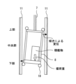
エレベーター1は、複数の階床を有する建物2に設けられる。建物2において、昇降路3が設けられる。昇降路3は、複数の階床にわたる空間である。建物2において、昇降路3の上部に機械室4が設けられる。建物2において、昇降路3の底部にピット5が設けられる。 An elevator 1 is provided in a building 2 having multiple floors. In the building 2, a hoistway 3 is provided. The hoistway 3 is a space spanning multiple floors. In the building 2, a machine room 4 is provided above the hoistway 3. In the building 2, a pit 5 is provided at the bottom of the hoistway 3.

エレベーター1は、巻上機6と、主ロープ7と、かご8と、釣合い錘9と、を備える。 The elevator 1 includes a hoist 6, a main rope 7, a car 8, and a counterweight 9.

巻上機6は、シーブおよびモータを備える。巻上機6のモータは、巻上機6のシーブを回転駆動する装置である。巻上機6は、例えば機械室4に設けられる。 The hoist 6 includes a sheave and a motor. The motor of the hoist 6 is a device that rotationally drives the sheave of the hoist 6. The hoist 6 is provided in the machine room 4, for example.

主ロープ7は、巻上機6のシーブに巻き掛けられる。主ロープ7の一端は、かご8に接続される。主ロープ7の他端は、釣合い錘9に接続される。エレベーター1は、複数の主ロープ7を備えていてもよい。 The main rope 7 is wound around a sheave of the hoist 6. One end of the main rope 7 is connected to a car 8. The other end of the main rope 7 is connected to a counterweight 9. The elevator 1 may include a plurality of main ropes 7.

かご8は、昇降路3において鉛直方向に走行することで複数の階床の間で利用者などを輸送する装置である。かご8は、利用者などが乗降しうるように開閉するかごドア10を備える。釣合い錘9は、主ロープ7を通じて巻上機6のシーブの両側にかかる荷重のバランスをかご8との間でとる装置である。かご8および釣合い錘9は、主ロープ7によって昇降路3において吊られる。かご8および釣合い錘9は、巻上機6が主ロープ7を巻き上げることによって昇降路3を互いに反対方向に走行する。かご8および釣合い錘9の各々は、昇降体の例である。 The car 8 is a device that transports users and the like between a plurality of floors by running vertically in the hoistway 3. The car 8 includes a car door 10 that opens and closes so that users can get on and off the car. The counterweight 9 is a device that balances the load applied to both sides of the sheave of the hoist 6 through the main rope 7 with respect to the car 8. The car 8 and the counterweight 9 are suspended in the hoistway 3 by the main rope 7. The car 8 and the counterweight 9 travel in opposite directions on the hoistway 3 as the hoist 6 winds up the main rope 7 . Each of the car 8 and the counterweight 9 is an example of an elevating body.

昇降路3において、一対のかごガイドレール11、一対の釣合い錘ガイドレール12、および複数のブラケット13が設けられる。 In the hoistway 3, a pair of car guide rails 11, a pair of counterweight guide rails 12, and a plurality of brackets 13 are provided.

一対のかごガイドレール11は、昇降路3におけるかご8の走行を案内する一対のガイドレールである。各々のかごガイドレール11は、昇降路3において鉛直方向に沿って配置される。一方のかごガイドレール11は、かご8の左側に配置される。他方のかごガイドレール11は、かご8の右側に配置される。 The pair of car guide rails 11 are a pair of guide rails that guide the travel of the car 8 in the hoistway 3. Each car guide rail 11 is arranged along the vertical direction in the hoistway 3. One car guide rail 11 is arranged on the left side of the car 8. The other car guide rail 11 is arranged on the right side of the car 8.

一対の釣合い錘ガイドレール12は、昇降路3における釣合い錘9の走行を案内する一対のガイドレールである。各々の釣合い錘ガイドレール12は、昇降路3において鉛直方向に沿って配置される。一方の釣合い錘ガイドレール12は、釣合い錘9の左側に配置される。他方の釣合い錘ガイドレール12は、釣合い錘9の右側に配置される。 The pair of counterweight guide rails 12 are a pair of guide rails that guide the travel of the counterweight 9 in the hoistway 3. Each counterweight guide rail 12 is arranged along the vertical direction in the hoistway 3. One counterweight guide rail 12 is arranged on the left side of the counterweight 9. The other counterweight guide rail 12 is arranged on the right side of the counterweight 9.

かご8または釣合い錘9などの昇降体は、かごガイドレール11または釣合い錘ガイドレール12などのガイドレールに沿って鉛直方向に走行する。昇降体の走行を案内するガイドレールの各々は、複数のブラケット13によって昇降路3に固定される。 An elevating body such as the car 8 or the counterweight 9 runs vertically along a guide rail such as the car guide rail 11 or the counterweight guide rail 12. Each of the guide rails that guide the movement of the elevating body is fixed to the hoistway 3 by a plurality of brackets 13.

エレベーター1は、地震感知器14と、制御盤15と、を備える。 The elevator 1 includes an earthquake sensor 14 and a control panel 15.

地震感知器14は、地震の発生を感知する部分である。地震感知器14は、例えばピット5に設けられる。このとき、地震感知器14は、例えばP波(Primary wave)によって地震を感知するP波感知器である。あるいは、地震感知器14は、例えば機械室4に設けられる。このとき、地震感知器14は、例えばS波(Secondary wave)によって地震を感知するS波感知器である。地震感知器14は、ピット5および機械室4の両方に設けられていてもよい。 The earthquake sensor 14 is a part that detects the occurrence of an earthquake. The earthquake sensor 14 is provided in the pit 5, for example. At this time, the earthquake sensor 14 is a P-wave sensor that detects earthquakes using, for example, P waves (Primary waves). Alternatively, the earthquake sensor 14 is provided in the machine room 4, for example. At this time, the earthquake sensor 14 is, for example, an S wave sensor that detects earthquakes using S waves (Secondary waves). Earthquake sensor 14 may be provided in both pit 5 and machine room 4.

制御盤15は、エレベーター1の動作を制御する装置である。制御盤15は、例えば機械室4に設けられる。制御盤15は、例えば巻上機6の動作の制御によってかご8および釣合い錘9の走行を制御する。また、制御盤15は、エレベーター1の運転モードを管理する。エレベーター1の運転モードは、通常運転と、地震時管制運転と、を含む。通常運転は、利用者によって登録された呼びなどに応答させるようにかご8を走行させる運転モードである。地震時管制運転は、エレベーター1において地震感知器14によって地震の発生が感知されたときの運転モードである。地震時管制運転において、制御盤15は、例えば走行しているかご8を最寄りの階床に停止させる。 The control panel 15 is a device that controls the operation of the elevator 1. The control panel 15 is provided in the machine room 4, for example. The control panel 15 controls the travel of the car 8 and the counterweight 9 by controlling the operation of the hoist 6, for example. Further, the control panel 15 manages the operation mode of the elevator 1. The operation modes of the elevator 1 include normal operation and earthquake control operation. The normal operation is an operation mode in which the car 8 is run so as to respond to calls registered by the user. The earthquake control operation is an operation mode when the earthquake sensor 14 in the elevator 1 detects the occurrence of an earthquake. In the earthquake control operation, the control panel 15 stops the running car 8 at the nearest floor, for example.

図2は、実施の形態1に係るかご8における偏荷重の例を示す図である。
図2において、正面から見たかご8が示される。
FIG. 2 is a diagram showing an example of an unbalanced load in the car 8 according to the first embodiment.
In FIG. 2, the car 8 is shown seen from the front.

かご8において、利用者または利用者が持ち込む重量物などがかご8の重心から離れた位置に乗ることで、偏荷重が生じることがある。図2に示す例において、かご8の右側に偏った荷重がかかっている。このとき、偏荷重によってかご8に傾きが生じる。ここで、かご8は主ロープ7によって吊られているので、偏荷重によって中央部を中心として回転するように傾く。ここで、中央部は、例えばかご8の重心を含む高さの部分である。この例において、かご8は偏荷重によって右側に傾く。 In the car 8, an unbalanced load may occur when the user or a heavy object brought by the user rides at a position away from the center of gravity of the car 8. In the example shown in FIG. 2, a load is applied to the right side of the car 8. At this time, the car 8 tilts due to the unbalanced load. Here, since the car 8 is suspended by the main rope 7, the car 8 is tilted so as to rotate about its center due to the unbalanced load. Here, the central portion is, for example, a portion at a height that includes the center of gravity of the car 8. In this example, the car 8 leans to the right due to the unbalanced load.

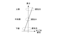
図3は、実施の形態1に係るかご8における偏荷重による変位の例を示す図である。
図3において、縦軸は、かご8における上下方向の位置を示す。図3において、横軸は、偏荷重によるかご8の水平方向の変位を示す。
FIG. 3 is a diagram showing an example of displacement due to an unbalanced load in the car 8 according to the first embodiment.
In FIG. 3, the vertical axis indicates the vertical position in the car 8. In FIG. 3, the horizontal axis indicates the horizontal displacement of the car 8 due to the unbalanced load.

かご8は中央部を中心として回転するように傾くため、かご8の中央部において偏荷重による水平方向の変位は小さい。一方、かご8の中央部から離れるにつれて偏荷重による水平方向の変位は大きくなる。かご8の上部および下部は、互いに反対方向に変位する。 Since the car 8 is tilted to rotate around the center, the horizontal displacement due to the unbalanced load at the center of the car 8 is small. On the other hand, the horizontal displacement due to the unbalanced load increases as the distance from the center of the car 8 increases. The upper and lower parts of the car 8 are displaced in opposite directions.

例えば地震などによってかご8が大きく変位する場合に、かご8などの昇降体に搭載された機器などが揺れの影響を受ける可能性がある。このとき、揺れの影響によって機器の損傷などが発生する場合に、エレベーター1の運行が影響を受ける可能性がある。このような事態を回避しうるように、エレベーター1の昇降体において変位抑制装置16が設けられる。変位抑制装置16は、昇降体の水平方向の変位を抑制する装置である。偏荷重によって昇降体が傾いているときに、図3に示されるように昇降体の上部および下部は中央部より大きく変位する。このため、中央部などの上下方向の一点において昇降体の変位を抑制しても、昇降体の上部または下部において変位が過剰になる可能性がある。このため、変位抑制装置16は、偏荷重によって昇降体が傾いているときに発生した地震の揺れにも対応しうるように、偏荷重で生じた傾きによる変位の影響を考慮して設けられる。 For example, when the car 8 is significantly displaced due to an earthquake or the like, equipment mounted on an elevating body such as the car 8 may be affected by the shaking. At this time, if equipment is damaged due to the effects of shaking, the operation of the elevator 1 may be affected. In order to avoid such a situation, a displacement suppressing device 16 is provided in the elevating body of the elevator 1. The displacement suppressing device 16 is a device that suppresses displacement of the elevating body in the horizontal direction. When the elevating body is tilted due to an unbalanced load, the upper and lower parts of the elevating body are displaced more than the center portion, as shown in FIG. For this reason, even if the displacement of the elevating body is suppressed at one point in the vertical direction, such as the center, the displacement may become excessive at the upper or lower part of the elevating body. For this reason, the displacement suppressing device 16 is provided in consideration of the influence of displacement due to the tilt caused by the uneven load so that it can also cope with earthquake shaking that occurs when the elevating body is tilted due to the uneven load.

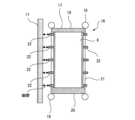
図4は、実施の形態1に係るかご8の正面図である。 FIG. 4 is a front view of the car 8 according to the first embodiment.

変位抑制装置16は、かご8に設けられる。かご8は、かご枠17と、複数のガイドシュー18と、を備える。 The displacement suppressing device 16 is provided in the car 8. The car 8 includes a car frame 17 and a plurality of guide shoes 18.

かご枠17は、上梁19と、下梁20と、一対の縦柱21と、を備える。上梁19は、かご8の上部において左端部および右端部の間にわたって配置される部材である。例えば上梁19において、主ロープ7が取り付けられる。下梁20は、かご8の下部において左端部および右端部の間にわたって配置される部材である。一対の縦柱21は、上梁19および下梁20の間にわたって配置される部材である。一方の縦柱21は、かご8の左端部に配置される。他方の縦柱21は、かご8の右端部に配置される。左側の縦柱21は、かご8の左側のかごガイドレール11に沿って配置される。右側の縦柱21は、かご8の右側のかごガイドレール11に沿って配置される。 The car frame 17 includes an upper beam 19, a lower beam 20, and a pair of vertical columns 21. The upper beam 19 is a member disposed at the upper part of the car 8 between the left end and the right end. For example, the main rope 7 is attached to the upper beam 19. The lower beam 20 is a member disposed at the lower part of the car 8 between the left end and the right end. The pair of vertical columns 21 are members arranged between the upper beam 19 and the lower beam 20. One vertical column 21 is arranged at the left end of the car 8. The other vertical column 21 is arranged at the right end of the car 8. The left vertical column 21 is arranged along the left car guide rail 11 of the car 8. The right vertical column 21 is arranged along the right car guide rail 11 of the car 8.

複数のガイドシュー18は、一対のかごガイドレール11によって案内される部分である。各々のガイドシュー18は、いずれかのかごガイドレール11に対向する。各々のガイドシュー18は、例えばかご枠17に取り付けられる。各々のガイドシュー18は、例えば上梁19または下梁20の左端部または右端部などに配置される。 The plurality of guide shoes 18 are portions that are guided by the pair of car guide rails 11. Each guide shoe 18 faces one of the car guide rails 11. Each guide shoe 18 is attached to the car frame 17, for example. Each guide shoe 18 is arranged, for example, at the left end or right end of the upper beam 19 or the lower beam 20.

変位抑制装置16は、複数のストッパ22を備える。各々のストッパ22は、かごガイドレール11によってかご8の変位を規制する部分である。各々のストッパ22は、例えば互いに同様の形状である。各々のストッパ22は、いずれかの縦柱21に取り付けられる。各々の縦柱21において、例えば互いに同数のストッパ22が取り付けられる。各々の縦柱21において、複数のストッパ22は上下方向に等間隔に並ぶ。各々の縦柱21において、複数のストッパ22は中央部に関して上下に対称に配置される。各々の縦柱21において、複数のストッパ22として5つのストッパ22が取り付けられる。なお、各々の縦柱21において、複数のストッパ22として偶数個のストッパ22が取り付けられていてもよい。また、いずれかのストッパ22は、上下方向においてガイドシュー18の外側に配置されていてもよい。すなわち、いずれかのストッパ22は、上梁19などのかご8の上側に配置されるガイドシュー18より上方、または下梁20などのかご8の下側に配置されるガイドシュー18より下方に配置されていてもよい。このとき、縦柱21は、上下方向においてガイドシュー18の外側まで延びていてもよい。あるいは、ガイドシュー18の外側において当該ストッパ22を支持する支持体がかご8に設けられていてもよい。 The displacement suppressing device 16 includes a plurality of stoppers 22 . Each stopper 22 is a portion that restricts displacement of the car 8 by the car guide rail 11. Each stopper 22 has, for example, a mutually similar shape. Each stopper 22 is attached to one of the vertical columns 21. For example, the same number of stoppers 22 are attached to each vertical column 21. In each vertical column 21, a plurality of stoppers 22 are arranged at regular intervals in the vertical direction. In each vertical column 21, a plurality of stoppers 22 are vertically symmetrically arranged with respect to the center portion. Five stoppers 22 are attached to each vertical column 21 as a plurality of stoppers 22. Note that an even number of stoppers 22 may be attached to each vertical column 21 as the plurality of stoppers 22. Further, any of the stoppers 22 may be arranged outside the guide shoe 18 in the vertical direction. That is, one of the stoppers 22 is arranged above the guide shoe 18 arranged above the car 8 such as the upper beam 19 or below the guide shoe 18 arranged below the car 8 such as the lower beam 20. may have been done. At this time, the vertical column 21 may extend to the outside of the guide shoe 18 in the vertical direction. Alternatively, the car 8 may be provided with a support that supports the stopper 22 on the outside of the guide shoe 18.

かご8の中央部は、第1位置の例である。かご8において第1位置より上方の位置は、第2位置の例である。かご8において第2位置よりさらに上方の位置は、第3位置の例である。この例において、第2位置および第3位置の間隔は、第1位置および第2位置の間隔に等しい。かご8において中央部に関して第2位置の上下に対称な位置は、対称位置の例である。 The center of the car 8 is an example of the first position. A position above the first position in the car 8 is an example of the second position. A position further above the second position in the car 8 is an example of the third position. In this example, the spacing between the second and third positions is equal to the spacing between the first and second positions. A position that is vertically symmetrical to the second position with respect to the center of the car 8 is an example of a symmetrical position.

各々のストッパ22は、隙間を空けてかごガイドレール11の表面に対向する。なお、図5などにおいて示される隙間の大きさは、説明のため誇張して示されている。各々のストッパ22およびかごガイドレール11の表面の隙間は、ストッパ22が設けられるかご8の位置に応じて設定される。 Each stopper 22 faces the surface of the car guide rail 11 with a gap between them. Note that the size of the gap shown in FIG. 5 and the like is exaggerated for the sake of explanation. The gap between each stopper 22 and the surface of the car guide rail 11 is set according to the position of the car 8 where the stopper 22 is provided.

この例において、中央部に配置されるストッパ22は、第1位置に配置される第1ストッパの例である。中央部に配置されるストッパ22の上方において隣接するストッパ22は、第2位置に配置される第2ストッパの例である。中央部に配置されるストッパ22の下方において隣接するストッパ22は、対称位置に配置される対称ストッパの例である。かご8において最も上方に配置されるストッパ22は、第3位置に配置される第3ストッパの例である。 In this example, the stopper 22 located at the center is an example of a first stopper located at the first position. The stopper 22 adjacent above the stopper 22 located at the center is an example of a second stopper located at the second position. The stoppers 22 that are adjacent below the stopper 22 located at the center are examples of symmetrical stoppers that are located at symmetrical positions. The stopper 22 disposed at the uppermost position in the car 8 is an example of a third stopper disposed at the third position.

第1ストッパは、第1隙間を空けてかごガイドレール11の表面に対向する。第2ストッパは、第2隙間を空けてかごガイドレール11の表面に対向する。第3ストッパは、第3隙間を空けてかごガイドレール11の表面に対向する。第2隙間は、第1隙間より大きい隙間である。第3隙間は、第2隙間より大きい隙間である。 The first stopper faces the surface of the car guide rail 11 with a first gap therebetween. The second stopper faces the surface of the car guide rail 11 with a second gap. The third stopper faces the surface of the car guide rail 11 with a third gap. The second gap is larger than the first gap. The third gap is larger than the second gap.

図5は、実施の形態1に係るかご8の水平断面図である。
図5において、かご8の中央部を通る水平面による断面図が示される。
FIG. 5 is a horizontal sectional view of the car 8 according to the first embodiment.
In FIG. 5, a cross-sectional view taken along a horizontal plane passing through the center of the car 8 is shown.

各々の縦柱21は、かご8の左右の端部において前後方向の中央に設けられる。 Each vertical column 21 is provided at the center of the left and right ends of the car 8 in the front-rear direction.

各々のストッパ22は、かごガイドレール11の前面、後面、および左右の内側面の三面の各々に対向する。ここで、左右の内側面は、かご8側の側面である。 Each stopper 22 faces each of the three surfaces of the car guide rail 11: the front surface, the rear surface, and the left and right inner surfaces. Here, the left and right inner surfaces are the sides on the car 8 side.

図6は、実施の形態1に係るストッパ22の水平断面図である。
図6において、いずれかのストッパ22を通る水平面による断面図が代表として示される。
FIG. 6 is a horizontal sectional view of the stopper 22 according to the first embodiment.
In FIG. 6, a cross-sectional view taken along a horizontal plane passing through one of the stoppers 22 is shown as a representative.

各々のストッパ22において、かごガイドレール11の前面およびストッパ22の隙間の大きさは、かごガイドレール11の左右の内側面およびストッパ22の隙間の大きさより小さい。また、かごガイドレール11の後面およびストッパ22の隙間の大きさは、かごガイドレール11の左右の内側面およびストッパ22の隙間の大きさより小さい。 In each stopper 22, the size of the gap between the front surface of the car guide rail 11 and the stopper 22 is smaller than the size of the gap between the left and right inner surfaces of the car guide rail 11 and the stopper 22. Further, the size of the gap between the rear surface of the car guide rail 11 and the stopper 22 is smaller than the size of the gap between the left and right inner surfaces of the car guide rail 11 and the stopper 22.

各々のストッパ22において、かごガイドレール11の前面およびストッパ22の隙間の大きさは、かごガイドレール11の後面およびストッパ22の隙間の大きさに等しい。また、左右の縦柱21の各々の同じ高さに配置されるストッパ22において、かごガイドレール11の左右の内側面およびストッパ22の隙間の大きさは互いに等しい。 In each stopper 22, the size of the gap between the front surface of the car guide rail 11 and the stopper 22 is equal to the size of the gap between the rear surface of the car guide rail 11 and the stopper 22. Moreover, in the stoppers 22 arranged at the same height of each of the left and right vertical columns 21, the sizes of the gaps between the left and right inner surfaces of the car guide rail 11 and the stoppers 22 are equal to each other.

なお、かご8における偏荷重は、利用者または利用者が持ち込む重量物によらずに生じる場合がある。かご8における偏荷重は、例えば主ロープ7などのローピングによって生じうる。あるいは、かご8における偏荷重は、例えば制御ケーブルまたはコンペンセーションロープが取り付けられる位置の偏りなどによって生じうる。この場合に、かごガイドレール11の前面およびストッパ22の隙間の大きさは、かごガイドレール11の後面およびストッパ22の隙間の大きさと異なっていてもよい。また、左右の縦柱21の各々の同じ高さに配置されるストッパ22において、かごガイドレール11の左右の内側面およびストッパ22の隙間の大きさは互いに異なっていてもよい。 Note that an unbalanced load on the car 8 may occur regardless of the user or the heavy objects brought by the user. Unbalanced loads on the car 8 can be caused by roping, such as the main rope 7, for example. Alternatively, an unbalanced load on the car 8 may be caused by, for example, an unbalanced position at which a control cable or a compensation rope is attached. In this case, the size of the gap between the front surface of the car guide rail 11 and the stopper 22 may be different from the size of the gap between the rear surface of the car guide rail 11 and the stopper 22. Moreover, in the stoppers 22 arranged at the same height of each of the left and right vertical columns 21, the sizes of the gaps between the left and right inner surfaces of the car guide rail 11 and the stoppers 22 may be different from each other.

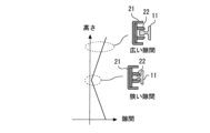
図7は、実施の形態1に係る変位抑制装置16における隙間の例を示す図である。
図7において、縦軸は、かご8における上下方向の位置を示す。図7において、横軸は、かごガイドレール11およびストッパ22の隙間の大きさを示す。図7において、かごガイドレール11の前面およびストッパ22の隙間と当該ストッパ22のかご8における上下方向の位置との関係が示される。
FIG. 7 is a diagram showing an example of a gap in the displacement suppressing device 16 according to the first embodiment.
In FIG. 7, the vertical axis indicates the vertical position in the car 8. In FIG. 7, the horizontal axis indicates the size of the gap between the car guide rail 11 and the stopper 22. In FIG. 7, the relationship between the gap between the front surface of the car guide rail 11 and the stopper 22 and the vertical position of the stopper 22 in the car 8 is shown.

かご8において中央部から離れた位置に配置されるストッパ22の隙間と中央部に配置されるストッパ22の隙間との大きさの差は、中央部からの遠さに比例する。中央部からの遠さは、例えば中央部との高さの差の絶対値などである。すなわち、第1隙間、第2隙間、および第3隙間の大きさは、例えばかご8の中央部からの遠さの1次関数によって関係づけられる。また、かごガイドレール11の前面およびストッパ22の隙間と当該ストッパ22のかご8における上下方向の位置との関係は、図7に示されるように中央部に関して対称な関係である。 The difference in size between the gap between the stoppers 22 disposed at a position away from the center of the car 8 and the gap between the stoppers 22 disposed at the center is proportional to the distance from the center. The distance from the center is, for example, the absolute value of the difference in height from the center. That is, the sizes of the first gap, the second gap, and the third gap are related, for example, by a linear function of the distance from the center of the car 8. Further, the relationship between the gap between the front surface of the car guide rail 11 and the stopper 22 and the vertical position of the stopper 22 in the car 8 is symmetrical with respect to the center, as shown in FIG.

なお、この例において、かごガイドレール11の後面およびストッパ22の隙間と当該ストッパ22のかご8における上下方向の位置との関係も、図7に示される関係と同様である。また、かごガイドレール11の左右の内側面およびストッパ22の隙間と当該ストッパ22のかご8における上下方向の位置との関係も、図7に示される関係と同様である。 In this example, the relationship between the gap between the rear surface of the car guide rail 11 and the stopper 22 and the vertical position of the stopper 22 in the car 8 is also the same as the relationship shown in FIG. 7 . Further, the relationship between the left and right inner surfaces of the car guide rail 11 and the gap between the stopper 22 and the vertical position of the stopper 22 in the car 8 is also the same as the relationship shown in FIG. 7 .

このような隙間が設定された複数のストッパ22を有することにより、変位抑制装置16は、偏荷重によってかご8が傾いている場合においても、かご8の上部またはかご8の下部の変位を抑制できる。これにより、変位抑制装置16は、偏荷重によってかご8が傾く場合においても、地震などの揺れに対するかご8の変位を安定して抑制できる。 By having a plurality of stoppers 22 with such gaps set, the displacement suppressing device 16 can suppress displacement of the upper part of the car 8 or the lower part of the car 8 even when the car 8 is tilted due to an unbalanced load. . Thereby, the displacement suppressing device 16 can stably suppress the displacement of the car 8 due to shaking caused by an earthquake, even when the car 8 is tilted due to an unbalanced load.

図8および図9は、実施の形態1に係るかご8における偏荷重の例を示す図である。
図8および図9において、上方から見たかご8が示される。
FIGS. 8 and 9 are diagrams showing examples of unbalanced loads in the car 8 according to the first embodiment.
In Figures 8 and 9, the car 8 is shown seen from above.

図8において、左右方向の偏荷重が生じている。左右方向の偏荷重が生じる場合に、かご8は左右方向に傾く。このとき、変位抑制装置16は、左右のいずれか一本のかごガイドレール11を通じて揺れなどによるかご8の変位を抑制する。 In FIG. 8, an unbalanced load in the left-right direction is occurring. When an unbalanced load occurs in the left-right direction, the car 8 tilts in the left-right direction. At this time, the displacement suppressing device 16 suppresses displacement of the car 8 due to shaking or the like through one of the left and right car guide rails 11.

一方、図9において、前後方向の偏荷重が生じている。前後方向の偏荷重が生じる場合に、かご8は前後方向に傾く。このとき、変位抑制装置16は、左右の両方のかごガイドレール11を通じて揺れなどによるかご8の変位を抑制する。このため、前後方向の変位を抑制するためのかごガイドレール11の表面およびストッパ22の隙間は、左右方向の変位を抑制するためのかごガイドレール11の表面およびストッパ22の隙間より小さくできる。 On the other hand, in FIG. 9, an unbalanced load in the front-rear direction is occurring. When an unbalanced load occurs in the front-rear direction, the car 8 tilts in the front-rear direction. At this time, the displacement suppressing device 16 suppresses displacement of the car 8 due to shaking etc. through both the left and right car guide rails 11. Therefore, the gap between the surface of the car guide rail 11 and the stopper 22 for suppressing displacement in the front-rear direction can be made smaller than the gap between the surface of the car guide rail 11 and the stopper 22 for suppressing displacement in the left-right direction.

なお、変位抑制装置16は、例えば第1ストッパおよび第2ストッパの間などにおいて、かごガイドレール11に対向する側の端部を上下方向において連続的に接続する部材を備えていてもよい。あるいは、変位抑制装置16において、複数のストッパ22の一部または全部は、上下方向において連続して縦柱21に設けられる部材の一部であってもよい。 Note that the displacement suppressing device 16 may include a member that continuously connects the end portion of the side facing the car guide rail 11 in the vertical direction, for example, between the first stopper and the second stopper. Alternatively, in the displacement suppressing device 16, some or all of the plurality of stoppers 22 may be part of a member continuously provided on the vertical column 21 in the vertical direction.

また、変位抑制装置16は、昇降体である釣合い錘9に設けられてもよい。このとき、釣合い錘9に設けられる変位抑制装置16は、かご8に設けられる変位抑制装置16と同様に作用することによって、釣合い錘9の変位を抑制する。釣合い錘9における偏荷重は、例えば主ロープ7などのローピングによって生じうる。あるいは、釣合い錘9における偏荷重は、例えばコンペンセーションロープが取り付けられる位置の偏りなどによって生じうる。 Further, the displacement suppressing device 16 may be provided on the counterweight 9, which is an elevating body. At this time, the displacement suppressing device 16 provided on the counterweight 9 acts in the same manner as the displacement suppressing device 16 provided on the car 8, thereby suppressing the displacement of the counterweight 9. Unbalanced loads on the counterweight 9 can be caused by roping, such as the main rope 7, for example. Alternatively, the unbalanced load on the counterweight 9 may be caused by, for example, the position where the compensation rope is unbalanced.

以上に説明したように、実施の形態1に係る昇降体の変位抑制装置16は、第1ストッパと、第2ストッパと、対称ストッパと、を備える。昇降体は、エレベーター1のガイドレールに沿って走行する。第1ストッパは、昇降体の上下方向における中央部にある第1位置に設けられる。第1ストッパは、第1隙間を空けてガイドレールに対向する。第2ストッパは、昇降体の第2位置に設けられる。第2位置は、第1位置から上下方向において離れている。第2ストッパは、第2隙間を空けてガイドレールに対向する。第2隙間は、第1隙間より大きい。対称ストッパは、昇降体の対称位置に設けられる。対称位置は、第1位置に関して上下方向において第2位置に対称な位置である。対称ストッパは、第2隙間と同じ大きさの隙間を空けてガイドレールに対向する。 As described above, the elevating body displacement suppressing device 16 according to the first embodiment includes a first stopper, a second stopper, and a symmetrical stopper . The elevating body runs along the guide rail of the elevator 1. The first stopper is provided at a first position in the center of the elevating body in the vertical direction . The first stopper faces the guide rail with a first gap therebetween. The second stopper is provided at a second position of the elevating body. The second position is separated from the first position in the vertical direction. The second stopper faces the guide rail with a second gap in between. The second gap is larger than the first gap. The symmetrical stoppers are provided at symmetrical positions on the elevating body. The symmetrical position is a position that is symmetrical to the second position in the vertical direction with respect to the first position. The symmetrical stopper faces the guide rail with a gap the same size as the second gap.

このような構成によって、変位抑制装置16は、偏荷重によって昇降体が傾いている場合においても、傾きによって昇降体の中央部より大きく変位した上部または下部の、揺れなどによる水平方向の変位を抑制できる。これにより、変位抑制装置16は、偏荷重によって昇降体が傾く場合においても、地震などの揺れに対する昇降体の変位を安定して抑制できる。すなわち、偏荷重による変位が第2位置より小さい第1位置において、第1隙間は第2隙間より小さいので、地震などの揺れに対する昇降体の変位が安定して抑制される。また、偏荷重による変位が第1位置より大きい第2位置において、第2隙間は第1隙間より大きいので、偏荷重によって昇降体が傾く場合であっても、通常運転における第2ストッパのガイドレールへの接触が抑えられる。これにより、ガイドレールおよびストッパ22の接触による異音、振動、または衝撃などの発生が抑えられる。このため、かご8に乗車している利用者の快適性が損なわれにくい。したがって、変位抑制装置16によって、偏荷重によって昇降体が傾く場合であっても、地震などの揺れに対する昇降体の変位の抑制と、通常運転におけるガイドレールおよびストッパ22の接触の抑制とが両立される。 With this configuration, the displacement suppressing device 16 suppresses horizontal displacement due to shaking, etc. of the upper or lower part of the elevating object, which is displaced more than the center of the elevating object due to the inclination, even when the elevating object is tilted due to an unbalanced load. can. Thereby, the displacement suppressing device 16 can stably suppress the displacement of the elevating object due to shaking such as an earthquake, even when the elevating object is tilted due to an unbalanced load. That is, at the first position where the displacement due to the unbalanced load is smaller than the second position, the first gap is smaller than the second gap, so the displacement of the elevating body due to shaking such as an earthquake is stably suppressed. In addition, at the second position where the displacement due to the unbalanced load is larger than the first position, the second gap is larger than the first gap, so even if the elevating body is tilted due to the unbalanced load, the guide rail of the second stopper in normal operation contact with is suppressed. This suppresses the occurrence of abnormal noise, vibration, impact, etc. due to contact between the guide rail and the stopper 22. Therefore, the comfort of the users riding in the car 8 is less likely to be impaired. Therefore, even if the elevating object is tilted due to an unbalanced load, the displacement suppressing device 16 can simultaneously suppress the displacement of the elevating object due to shaking such as an earthquake, and suppress contact between the guide rail and the stopper 22 during normal operation. Ru.

また、変位抑制装置16は、対称ストッパを備える。対称ストッパは、昇降体の対称位置に設けられる。対称位置は、昇降体の中央部に関して上下方向において第2位置に対称な位置である。対称ストッパは、第2隙間と同じ大きさの隙間を空けてガイドレールに対向する。 The displacement suppressing device 16 also includes a symmetrical stopper. The symmetrical stoppers are provided at symmetrical positions on the elevating body. The symmetrical position is a position that is symmetrical to the second position in the vertical direction with respect to the central portion of the elevating body. The symmetrical stopper faces the guide rail with a gap the same size as the second gap.

このような構成によって、変位抑制装置16は、偏荷重による傾きによって上部または下部のいずれがガイドレールに近づくように変位した場合においても、地震などの揺れに対する昇降体の変位を安定して抑制できる。 With such a configuration, the displacement suppressing device 16 can stably suppress the displacement of the elevating body due to shaking caused by an earthquake, even if either the upper or lower part is displaced to approach the guide rail due to tilt due to unbalanced load. .

また、変位抑制装置16は、第3ストッパを備える。第3ストッパは、第3位置に設けられる。第3位置は、昇降体の中央部から第2位置より上下方向において離れている。第3ストッパは、第3隙間を空けてガイドレールに対向する。第3隙間は、第2隙間より大きい。第1隙間の大きさ、第2隙間の大きさ、および第3隙間の大きさは、中央部からの遠さの1次関数によって関係づけられる。 Further, the displacement suppressing device 16 includes a third stopper. The third stopper is provided at the third position. The third position is further away from the center of the elevating body than the second position in the vertical direction. The third stopper faces the guide rail with a third gap in between. The third gap is larger than the second gap. The size of the first gap, the size of the second gap, and the size of the third gap are related by a linear function of distance from the center.

このような構成によって、変位抑制装置16は、直線的なガイドレールの表面に沿って揺れなどによる昇降体の変位を抑制できる。このため、変位抑制装置16は、地震などの揺れに対する昇降体の変位をより安定して抑制できる。 With such a configuration, the displacement suppressing device 16 can suppress displacement of the elevating body due to shaking or the like along the surface of the linear guide rail. Therefore, the displacement suppressing device 16 can more stably suppress the displacement of the elevating body due to shaking such as an earthquake.

また、第1ストッパは、ガイドレールの前面、後面、および左右の内側面の三面の各々に対向する。第2ストッパは、ガイドレールの前面、後面、および左右の内側面の三面の各々に対向する。ガイドレールの前面との間の第2隙間は、ガイドレールの前面との間の第1隙間より大きい。ガイドレールの後面との間の第2隙間は、ガイドレールの後面との間の第1隙間より大きい。ガイドレールの左右の内側面との間の第2隙間は、ガイドレールの左右の内側面との間の第1隙間より大きい。 Further, the first stopper faces each of the three surfaces, the front surface, the rear surface, and the left and right inner surfaces of the guide rail. The second stopper faces each of the three surfaces, the front surface, the rear surface, and the left and right inner surfaces of the guide rail. The second gap with the front surface of the guide rail is larger than the first gap with the front surface of the guide rail. The second gap with the rear surface of the guide rail is larger than the first gap with the rear surface of the guide rail. The second gap between the left and right inner surfaces of the guide rail is larger than the first gap between the left and right inner surfaces of the guide rail.

このような構成によって、昇降体の変位はガイドレールによって3方向から抑制される。これにより、変位の抑制がより安定に行われる。 With such a configuration, the displacement of the elevating body is suppressed from three directions by the guide rail. Thereby, displacement can be suppressed more stably.

また、ガイドレールの前面との間の第1隙間またはガイドレールの後面との間の第1隙間の少なくとも一方は、ガイドレールの内側面との間の第1隙間より小さい。
また、ガイドレールの前面との間の第2隙間またはガイドレールの後面との間の第2隙間の少なくとも一方は、ガイドレールの内側面との間の第2隙間より小さい。
Moreover, at least one of the first gap with the front surface of the guide rail and the first gap with the rear surface of the guide rail is smaller than the first gap with the inner surface of the guide rail.
Furthermore, at least one of the second gap between the guide rail and the front surface of the guide rail and the second gap between the guide rail and the rear surface of the guide rail is smaller than the second gap between the guide rail and the inner surface of the guide rail.

このような構成において、昇降体の傾きやすさなどに応じて変位を抑制する隙間の大きさが調整される。このため、隙間が大きすぎることによって変位が十分抑制されないことを回避しうる。また、隙間が小さすぎることによってストッパ22およびガイドレールが接触することを回避しうる。これにより、ガイドレールおよびストッパ22の接触による異音、振動、または衝撃などの発生が抑えられる。このため、かご8に乗車している利用者の快適性が損なわれにくい。 In such a configuration, the size of the gap that suppresses displacement is adjusted depending on how easily the elevating body is inclined. Therefore, it is possible to avoid displacement being insufficiently suppressed due to the gap being too large. Furthermore, it is possible to avoid contact between the stopper 22 and the guide rail due to the gap being too small. This suppresses the occurrence of abnormal noise, vibration, impact, etc. due to contact between the guide rail and the stopper 22. Therefore, the comfort of the users riding in the car 8 is less likely to be impaired.

なお、かご8などの昇降体において上下方向に並ぶ複数のストッパ22は、不等間隔に配置されていてもよい。例えば、複数のストッパ22は、隣接するストッパとの上下方向の間隔が昇降体の中央部から離れるほど小さくなるように配置されてもよい。このとき、中央部より上方に配置されるストッパ22について、上側に隣接するストッパ22との上下方向における間隔は、下側に隣接するストッパ22との上下方向における間隔より小さい。また、中央部より下方に配置されるストッパ22について、下側に隣接するストッパ22との上下方向における間隔は、上側に隣接するストッパ22との上下方向における間隔より小さい。 In addition, the plurality of stoppers 22 arranged in the vertical direction in an elevating object such as the car 8 may be arranged at unequal intervals. For example, the plurality of stoppers 22 may be arranged such that the distance between adjacent stoppers in the vertical direction becomes smaller as the distance from the center of the elevating body increases. At this time, with respect to the stopper 22 disposed above the center, the distance in the vertical direction from the stopper 22 adjacent to the upper side is smaller than the distance in the vertical direction from the stopper 22 adjacent to the lower side. Further, regarding the stopper 22 disposed below the center portion, the distance in the vertical direction between the stopper 22 and the stopper 22 adjacent to the lower side is smaller than the distance in the vertical direction between the stopper 22 and the stopper 22 adjacent to the upper side.

縦柱21の上端部は上梁19に接続され、縦柱21の下端部は下梁20に接続されているので、縦柱21の水平方向における剛性は、中央部から離れるほど高くなる。剛性が高い位置において、縦柱21は、ストッパ22を通じてガイドレールから反力を受けても変形しにくい。縦柱21がガイドレールから逃げるように変形しにくいので、剛性が高い位置に設けられたストッパ22において、昇降体の変位抑制の効果は低下しにくい。このため、中央部から離れるほど密になるように配置された複数のストッパ22によって、縦柱21の剛性が高い位置において昇降体の変位が効率的に抑えられる。 Since the upper end of the vertical column 21 is connected to the upper beam 19 and the lower end of the vertical column 21 is connected to the lower beam 20, the rigidity of the vertical column 21 in the horizontal direction increases as the distance from the center increases. At a position where the rigidity is high, the vertical column 21 is difficult to deform even if it receives a reaction force from the guide rail through the stopper 22. Since the vertical column 21 is difficult to deform to escape from the guide rail, the effect of suppressing displacement of the elevating body is less likely to decrease in the stopper 22 provided at a position with high rigidity. Therefore, the displacement of the elevating body can be effectively suppressed at the position where the vertical column 21 has high rigidity by the plurality of stoppers 22 arranged so as to become denser as the distance from the center increases.

実施の形態2.
実施の形態2において、実施の形態1で開示される例と相違する点について特に詳しく説明する。実施の形態2で説明しない特徴については、実施の形態1で開示される例のいずれの特徴が採用されてもよい。
Embodiment 2.
In Embodiment 2, points that are different from the example disclosed in Embodiment 1 will be explained in particular detail. As for the features not described in the second embodiment, any of the features in the examples disclosed in the first embodiment may be adopted.

図10は、実施の形態2に係るかご8における偏荷重による傾きの例を示す図である。
図10において、正面から見たかご8が示される。
FIG. 10 is a diagram showing an example of inclination due to an unbalanced load in the car 8 according to the second embodiment.
In FIG. 10, the car 8 is shown seen from the front.

偏荷重によってかご8が傾くときに、かごガイドレール11はかご8からの反力によってたわみなどの変形を生じることがある。 When the car 8 is tilted due to an unbalanced load, the car guide rail 11 may undergo deformation such as deflection due to the reaction force from the car 8.

図11は、実施の形態2に係るかご8における偏荷重による変位の例を示す図である。
図11において、縦軸は、かご8における上下方向の位置を示す。図11において、横軸は、偏荷重によるかご8の水平方向の変位、およびかごガイドレール11の変形による変位を示す。
FIG. 11 is a diagram showing an example of displacement due to an unbalanced load in the car 8 according to the second embodiment.
In FIG. 11, the vertical axis indicates the vertical position in the car 8. In FIG. 11, the horizontal axis indicates the horizontal displacement of the car 8 due to unbalanced loads and the displacement due to deformation of the car guide rail 11.

かごガイドレール11およびストッパ22の隙間は、かご8の傾きによる変位および当該傾きによるかごガイドレール11の変形による変位の差によって変化する。ここで、かごガイドレール11は、鉛直方向において曲線的に変形しうる。 The gap between the car guide rail 11 and the stopper 22 changes depending on the difference between the displacement due to the inclination of the car 8 and the displacement due to the deformation of the car guide rail 11 due to the inclination. Here, the car guide rail 11 can be deformed into a curve in the vertical direction.

図12は、実施の形態2に係る変位抑制装置16における隙間の例を示す図である。
図12において、縦軸は、かご8における上下方向の位置を示す。図12において、横軸は、かごガイドレール11およびストッパ22の隙間の大きさを示す。図12において、かごガイドレール11の前面およびストッパ22の隙間と当該ストッパ22のかご8における上下方向の位置との関係が示される。
FIG. 12 is a diagram showing an example of a gap in the displacement suppressing device 16 according to the second embodiment.
In FIG. 12, the vertical axis indicates the vertical position in the car 8. In FIG. 12, the horizontal axis indicates the size of the gap between the car guide rail 11 and the stopper 22. In FIG. 12, the relationship between the gap between the front surface of the car guide rail 11 and the stopper 22 and the vertical position of the stopper 22 in the car 8 is shown.

かご8において中央部から離れた位置に配置されるストッパ22の隙間と中央部に配置されるストッパ22の隙間との大きさの差は、中央部からの遠さの単調増加関数に従う。ここで、当該関数は、偏荷重によって生じるかご8の傾きおよび当該傾きによるかごガイドレール11の変形量に基づいて予め設定された非線形な関数である。当該関数は、例えば中央部からの遠さに関する凸関数または凹関数などである。すなわち、変位抑制装置16が第1ストッパ、第2ストッパ、および第3ストッパを有する場合に、第1隙間、第2隙間、および第3隙間の大きさは、当該関数によってかご8の中央部からの遠さと関係づけられる。 The difference in size between the gap between the stoppers 22 located away from the center of the car 8 and the gap between the stoppers 22 located at the center follows a monotonically increasing function of the distance from the center. Here, the function is a nonlinear function that is preset based on the inclination of the car 8 caused by the unbalanced load and the amount of deformation of the car guide rail 11 due to the inclination. The function is, for example, a convex function or a concave function regarding distance from the center. That is, when the displacement suppressing device 16 has a first stopper, a second stopper, and a third stopper, the sizes of the first gap, the second gap, and the third gap are determined by the function from the center of the car 8. It is associated with the distance of

なお、この例において、かごガイドレール11の後面およびストッパ22の隙間と当該ストッパ22のかご8における上下方向の位置との関係も、図12に示される関係と同様であってもよい。また、かごガイドレール11の左右の内側面およびストッパ22の隙間と当該ストッパ22のかご8における上下方向の位置との関係も、図12に示される関係と同様であってもよい。 In this example, the relationship between the gap between the rear surface of the car guide rail 11 and the stopper 22 and the vertical position of the stopper 22 in the car 8 may be the same as the relationship shown in FIG. 12. Further, the relationship between the left and right inner surfaces of the car guide rail 11 and the gap between the stopper 22 and the vertical position of the stopper 22 in the car 8 may be the same as the relationship shown in FIG. 12.

以上に説明したように、実施の形態2に係る変位抑制装置16は、第3ストッパを備える。第3ストッパは、第3位置に設けられる。第3位置は、昇降体の中央部から第2位置より上下方向において離れている。第3ストッパは、第3隙間を空けてガイドレールに対向する。第3隙間は、第2隙間より大きい。第1隙間の大きさ、第2隙間の大きさ、および第3隙間の大きさは、中央部からの遠さの関数によって関係づけられる。当該関数は、昇降体の偏荷重によって生じる傾きおよび当該傾きによるガイドレールの変形量に基づく非線形な関数である。 As explained above, the displacement suppressing device 16 according to the second embodiment includes the third stopper. The third stopper is provided at the third position. The third position is further away from the center of the elevating body than the second position in the vertical direction. The third stopper faces the guide rail with a third gap in between. The third gap is larger than the second gap. The size of the first gap, the size of the second gap, and the size of the third gap are related by a function of distance from the center. This function is a nonlinear function based on the inclination caused by the unbalanced load of the elevating body and the amount of deformation of the guide rail due to the inclination.

このような構成において、変位抑制装置16は、ガイドレールの変形を考慮して揺れなどによる昇降体の変位を抑制できる。このため、変位抑制装置16は、ガイドレールが変形する場合においても、地震などの揺れに対する昇降体の変位を安定して抑制できる。 In such a configuration, the displacement suppressing device 16 can suppress the displacement of the elevating body due to shaking, etc., taking into account the deformation of the guide rail. Therefore, even when the guide rail is deformed, the displacement suppressing device 16 can stably suppress the displacement of the elevating body due to shaking such as an earthquake.

実施の形態3.
実施の形態3において、実施の形態1または実施の形態2で開示される例と相違する点について特に詳しく説明する。実施の形態3で説明しない特徴については、実施の形態1または実施の形態2で開示される例のいずれの特徴が採用されてもよい。
Embodiment 3.
In Embodiment 3, points that are different from the examples disclosed in Embodiment 1 or Embodiment 2 will be explained in particular detail. For features not described in Embodiment 3, any of the features disclosed in Embodiment 1 or Embodiment 2 may be adopted.

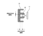
図13は、実施の形態3に係るストッパ22の上面図である。
図13において、上方から見たストッパ22が示される。
FIG. 13 is a top view of the stopper 22 according to the third embodiment.
In FIG. 13, the stopper 22 is shown seen from above.

変位抑制装置16において第1ストッパ、第2ストッパ、第3ストッパ、および対称ストッパなどを含む複数のストッパ22の各々は、シュー23およびアクチュエータ24の組を1つ以上備える。この例において、ストッパ22は、シュー23およびアクチュエータ24の組を3組備える。3組のうちのいずれか1組において、シュー23は、かごガイドレール11の前面に対向する。3組のうちの他の1組において、シュー23は、かごガイドレール11の後面に対向する。3組のうちの残りの1組において、シュー23は、かごガイドレール11の左右の内側面に対向する。各々の組において、アクチュエータ24は、シュー23を移動させることでかごガイドレール11およびシュー23の隙間を変化させる。なお、複数のストッパ22の一部または全部において、シュー23およびアクチュエータ24の組のいずれか1つまたは2つが省略されてもよい。 In the displacement suppressing device 16, each of the plurality of stoppers 22 including a first stopper, a second stopper, a third stopper, a symmetrical stopper, etc. includes one or more sets of a shoe 23 and an actuator 24. In this example, the stopper 22 includes three pairs of shoes 23 and actuators 24. In any one of the three sets, the shoe 23 faces the front surface of the car guide rail 11. In the other one of the three pairs, the shoe 23 faces the rear surface of the car guide rail 11. In the remaining one of the three pairs, the shoes 23 face the left and right inner surfaces of the car guide rail 11. In each set, the actuator 24 changes the gap between the car guide rail 11 and the shoe 23 by moving the shoe 23. Note that in some or all of the plurality of stoppers 22, one or two of the pairs of shoe 23 and actuator 24 may be omitted.

第1ストッパにおける各々の組のシュー23は、第1シューの例である。かごガイドレール11および第1シューは、第1隙間を空けて対向する。第1ストッパにおける各々の組のアクチュエータ24は、第1アクチュエータの例である。第2ストッパにおける各々の組のシュー23は、第2シューの例である。かごガイドレール11および第2シューは、第2隙間を空けて対向する。第2ストッパにおける各々の組のアクチュエータ24は、第2アクチュエータの例である。 Each set of shoes 23 in the first stopper is an example of a first shoe. The car guide rail 11 and the first shoe face each other with a first gap in between. Each set of actuators 24 in the first stop is an example of a first actuator. Each set of shoes 23 in the second stopper is an example of a second shoe. The car guide rail 11 and the second shoe face each other with a second gap in between. Each set of actuators 24 in the second stop is an example of a second actuator.

図14は、実施の形態3に係る変位抑制装置16の構成図である。
図14において、正面から見たかご8が示される。
FIG. 14 is a configuration diagram of the displacement suppressing device 16 according to the third embodiment.
In FIG. 14, the car 8 is shown seen from the front.

かご8において、秤装置25が設けられる。秤装置25は、かご8の下部に設けられる。秤装置25は、かご8における偏荷重を計測する偏荷重計測部の例である。秤装置25は、計測した偏荷重を外部の機器に出力する機能を搭載する。 In the car 8, a weighing device 25 is provided. The weighing device 25 is provided at the bottom of the car 8. The weighing device 25 is an example of an unbalanced load measuring section that measures the unbalanced load on the car 8. The weighing device 25 is equipped with a function of outputting the measured unbalanced load to an external device.

変位抑制装置16は、制御部26を備える。制御部26は、各々のストッパ22におけるアクチュエータ24の動作を制御する部分である。制御部26は、例えばかご8の上部に設けられる。あるいは、制御部26は、例えばエレベーター1の制御盤15に搭載されていてもよい。あるいは、変位抑制装置16は、各々のストッパ22に1対1に対応する個別の制御部26を備えていてもよい。あるいは、変位抑制装置16は、各々のアクチュエータ24に1対1に対応する個別の制御部26を備えてもよい。制御部26は、かご8の偏荷重の計測結果を取得しうるように、秤装置25などの偏荷重計測部に接続される。 The displacement suppressing device 16 includes a control section 26 . The control unit 26 is a part that controls the operation of the actuator 24 in each stopper 22. The control unit 26 is provided, for example, at the top of the car 8. Alternatively, the control unit 26 may be mounted on the control panel 15 of the elevator 1, for example. Alternatively, the displacement suppressing device 16 may include an individual control section 26 corresponding to each stopper 22 on a one-to-one basis. Alternatively, the displacement suppressing device 16 may include an individual control section 26 corresponding to each actuator 24 on a one-to-one basis. The control unit 26 is connected to an unbalanced load measuring unit such as a weighing device 25 so as to obtain the measurement result of the unbalanced load of the car 8.

続いて、変位抑制装置16の動作の例を説明する。 Next, an example of the operation of the displacement suppressing device 16 will be explained.

通常運転において、秤装置25は、かご8における偏荷重を計測する。秤装置25は、計測された偏荷重を制御部26に出力する。 During normal operation, the weighing device 25 measures the unbalanced load on the car 8. The weighing device 25 outputs the measured unbalanced load to the control unit 26.

制御部26は、秤装置25から入力された偏荷重に基づいて、かご8の傾きを算出する。制御部26は、算出されたかご8の傾きに応じて、各々のストッパ22におけるかごガイドレール11との隙間の変化を算出する。制御部26は、算出した隙間の変化に基づいて、各々のストッパ22においてかごガイドレール11との隙間が予め設定された範囲に収まるように各々のアクチュエータ24を動作させる。当該範囲は、地震などの揺れにおけるかご8の変位をかごガイドレール11によって抑制しうるように予め設定された範囲である。 The control unit 26 calculates the inclination of the car 8 based on the unbalanced load input from the weighing device 25. The control unit 26 calculates a change in the gap between each stopper 22 and the car guide rail 11 according to the calculated inclination of the car 8. Based on the calculated change in the gap, the control unit 26 operates each actuator 24 so that the gap between each stopper 22 and the car guide rail 11 falls within a preset range. This range is a range set in advance so that the car guide rail 11 can suppress displacement of the car 8 due to shaking such as an earthquake.

一方、地震時管制運転において、各々のアクチュエータ24は、秤装置25による偏荷重の計測結果に関わらずにかごガイドレール11および各々のシュー23の隙間を狭い状態で維持する。これにより、地震の揺れなどによるかご8の変位は、かごガイドレール11を通じて抑制される。 On the other hand, in the earthquake control operation, each actuator 24 maintains the gap between the car guide rail 11 and each shoe 23 in a narrow state regardless of the measurement result of the unbalanced load by the scale device 25. As a result, displacement of the car 8 due to earthquake shaking or the like is suppressed through the car guide rail 11.

なお、かご8において、図示されない傾斜計測部が設けられていてもよい。傾斜計測部は、かご8の傾きを計測する部分である。傾斜計測部は、例えばかご8の上部または下部などに配置される。傾斜計測部は、例えば傾斜センサ、加速度センサ、またはジャイロセンサなどを備える。傾斜計測部は、かご8の傾きの計測結果を出力する機能を搭載する。 Note that the car 8 may be provided with an inclination measuring section (not shown). The inclination measuring section is a part that measures the inclination of the car 8. The inclination measuring section is arranged, for example, at the top or bottom of the car 8. The tilt measurement unit includes, for example, a tilt sensor, an acceleration sensor, or a gyro sensor. The inclination measuring section is equipped with a function of outputting the measurement result of the inclination of the car 8.

通常運転において、制御部26は、傾斜計測部から入力されたかご8の傾きに応じて、各々のストッパ22におけるかごガイドレール11との隙間の変化を算出する。制御部26は、算出した隙間の変化に基づいて、各々のストッパ22の各々のシュー23においてかごガイドレール11との隙間が予め設定された範囲に収まるように各々のアクチュエータ24を動作させる。 During normal operation, the control unit 26 calculates a change in the gap between each stopper 22 and the car guide rail 11 according to the inclination of the car 8 input from the inclination measurement unit. Based on the calculated change in the gap, the control unit 26 operates each actuator 24 so that the gap between each shoe 23 of each stopper 22 and the car guide rail 11 falls within a preset range.

一方、地震時管制運転において、各々のアクチュエータ24は、傾斜計測部による傾きの計測結果に関わらずにかごガイドレール11および各々のシュー23の隙間を狭い状態で維持する。これにより、地震の揺れなどによるかご8の変位は、かごガイドレール11を通じて抑制される。 On the other hand, in the earthquake control operation, each actuator 24 maintains the gap between the car guide rail 11 and each shoe 23 in a narrow state regardless of the measurement result of the inclination by the inclination measuring section. As a result, displacement of the car 8 due to earthquake shaking or the like is suppressed through the car guide rail 11.

また、かご8において、図示されないロードセルなどの荷重計が設けられていてもよい。荷重計は、例えば少なくともいずれかのガイドシュー18などに設けられる。荷重計は、ガイドシュー18が受けるかごガイドレール11からの水平反力を計測する機器である。ガイドシュー18が受ける水平反力はかご8の傾きに依るので、荷重計によってかご枠17全体の傾きが計測される。すなわち、荷重計は、傾斜計測部の他の例として機能する。荷重系によってかご枠17全体の傾きが計測されるので、例えば制御ケーブルまたはコンペンセーションロープが取り付けられる位置の偏りなどによって生じる傾きも高い精度で計測される。 Furthermore, the car 8 may be provided with a load meter such as a load cell (not shown). The load meter is provided on at least one of the guide shoes 18, for example. The load meter is a device that measures the horizontal reaction force from the car guide rail 11 that the guide shoe 18 receives. Since the horizontal reaction force that the guide shoe 18 receives depends on the inclination of the car 8, the inclination of the entire car frame 17 is measured by a load meter. That is, the load meter functions as another example of the inclination measuring section. Since the inclination of the entire car frame 17 is measured by the load system, inclinations caused by, for example, deviations in the positions where control cables or compensation ropes are attached can also be measured with high precision.

図15は、実施の形態3の第1の変形例に係る変位抑制装置16の構成図である。
図15において、正面から見たかご8が示される。
FIG. 15 is a configuration diagram of a displacement suppressing device 16 according to a first modification of the third embodiment.
In FIG. 15, the car 8 is shown seen from the front.

かご8において、カメラ27が設けられる。カメラ27は、かご8の内部に設けられる。カメラ27は撮影したかご8の内部の画像の画像認識などによってかご8における偏荷重を算出する。この例において、カメラ27は、かご8における偏荷重を計測する偏荷重計測部の例である。制御部26は、偏荷重計測部の例であるカメラ27から入力される偏荷重の情報に基づいて、かご8の傾きを算出する。制御部26は、算出したかご8の傾きに応じて各々のアクチュエータ24を動作させる。 A camera 27 is provided in the car 8. Camera 27 is provided inside car 8. The camera 27 calculates the unbalanced load on the car 8 by image recognition of the photographed image of the inside of the car 8. In this example, the camera 27 is an example of an unbalanced load measuring section that measures the unbalanced load in the car 8. The control unit 26 calculates the inclination of the car 8 based on information on the unbalanced load input from the camera 27, which is an example of an unbalanced load measuring unit. The control unit 26 operates each actuator 24 according to the calculated inclination of the car 8.

図16は、実施の形態3の第2の変形例に係る変位抑制装置16の構成図である。
図16において、上方から見たストッパ22が示される。
FIG. 16 is a configuration diagram of a displacement suppressing device 16 according to a second modification of the third embodiment.
In FIG. 16, the stopper 22 is shown seen from above.

変位抑制装置16は、隙間計測部28を備える。隙間計測部28は、かごガイドレール11およびストッパ22の隙間を計測する部分である。隙間計測部28は、第1ストッパ、第2ストッパ、第3ストッパ、および対称ストッパなどを含む複数のストッパ22の少なくともいずれかのストッパ22について隙間の計測を行う。この例において、隙間計測部28は、第1ストッパおよび第2ストッパについて隙間の計測を行う。 The displacement suppressing device 16 includes a gap measuring section 28 . The gap measuring section 28 is a part that measures the gap between the car guide rail 11 and the stopper 22. The gap measurement unit 28 measures the gap for at least one of the plurality of stoppers 22 including a first stopper, a second stopper, a third stopper, a symmetrical stopper, and the like. In this example, the gap measurement unit 28 measures the gap between the first stopper and the second stopper.

隙間計測部28は、複数の距離センサ29を有する。この例において、2つの距離センサ29が第1ストッパに対応する。一方の距離センサ29は、かごガイドレール11の前面に対向するシュー23と前面との隙間を計測する。他方の距離センサ29は、かごガイドレール11の左右の内側面に対向するシュー23と内側面との隙間を計測する。隙間計測部28の複数の距離センサ29は、第2ストッパに対応して同様に隙間を計測する2つの距離センサ29を含む。隙間計測部28は、複数の距離センサ29によって計測した隙間の各々の大きさを制御部26に出力する。 The gap measurement section 28 has a plurality of distance sensors 29. In this example, two distance sensors 29 correspond to the first stop. One distance sensor 29 measures the gap between the shoe 23 facing the front surface of the car guide rail 11 and the front surface. The other distance sensor 29 measures the gap between the inner surface and the shoe 23 that faces the left and right inner surfaces of the car guide rail 11 . The plurality of distance sensors 29 of the gap measuring section 28 include two distance sensors 29 corresponding to the second stopper and similarly measuring the gap. The gap measurement unit 28 outputs the size of each gap measured by the plurality of distance sensors 29 to the control unit 26.

制御部26は、隙間計測部28から入力された隙間の大きさに応じて、各々のストッパ22の各々のシュー23においてかごガイドレール11との隙間が予め設定された範囲に収まるように各々のアクチュエータ24を動作させる。制御部26は、少なくともいずれかのストッパ22において、例えばかごガイドレール11の前面に対向するシュー23と前面との隙間の大きさの計測値に基づいて、かごガイドレール11の後面に対向するシュー23と後面との隙間の大きさを推定してもよい。このとき、制御部26は、推定した隙間の大きさに応じて、各々のストッパ22の各々のシュー23においてかごガイドレール11との隙間が予め設定された範囲に収まるように各々のアクチュエータ24を動作させる。また、制御部26は、いずれかのストッパ22に設けられる距離センサ29において計測された隙間の大きさに基づいて、かご8の傾きを推定してもよい。このとき、制御部26は、推定した傾きに基づいて各々のアクチュエータ24を動作させる。ここで、制御部26は、隙間計測部28が隙間の大きさを計測していないストッパ22についても、推定した傾きに基づいて各々のアクチュエータ24を動作させてもよい。 The control unit 26 adjusts each shoe 23 of each stopper 22 so that the gap with the car guide rail 11 falls within a preset range according to the size of the gap input from the gap measurement unit 28. Actuator 24 is operated. The control unit 26 controls, in at least one of the stoppers 22, the shoe 23 facing the front surface of the car guide rail 11, based on the measured value of the gap between the front surface and the shoe 23 facing the front surface of the car guide rail 11. The size of the gap between 23 and the rear surface may be estimated. At this time, the control unit 26 controls each actuator 24 so that the gap between each shoe 23 of each stopper 22 and the car guide rail 11 falls within a preset range according to the estimated gap size. make it work. Further, the control unit 26 may estimate the inclination of the car 8 based on the size of the gap measured by the distance sensor 29 provided in one of the stoppers 22. At this time, the control unit 26 operates each actuator 24 based on the estimated inclination. Here, the control unit 26 may operate each actuator 24 based on the estimated inclination even for the stoppers 22 for which the gap measurement unit 28 has not measured the size of the gap.

一方、地震時管制運転において、各々のアクチュエータ24は、隙間計測部28による隙間の計測結果に関わらずにかごガイドレール11および各々のシュー23の隙間を狭い状態で維持する。これにより、地震の揺れなどによるかご8の変位は、かごガイドレール11を通じて抑制される。 On the other hand, in the earthquake control operation, each actuator 24 maintains the gap between the car guide rail 11 and each shoe 23 in a narrow state regardless of the gap measurement result by the gap measurement section 28. As a result, displacement of the car 8 due to earthquake shaking or the like is suppressed through the car guide rail 11.

なお、かご8に取り付けられる制御ケーブルまたはコンペンセーションロープなどは、かご8の位置によって変動する。このため、例えば制御ケーブルなどが取り付けられる位置の偏りなどによってかご8において偏荷重が生じる場合に、かご8の偏荷重もかご8の位置によって同様に変動する。このとき、制御部26は、かご8の位置に基づいてかご8の偏荷重、傾き、またはかごガイドレール11およびストッパ22の隙間などを推定してもよい。制御部26は、かご8の位置に推定の結果に応じて各々のアクチュエータ24を動作させる。 Note that the control cable or compensation rope attached to the car 8 varies depending on the position of the car 8. Therefore, if an uneven load is generated in the car 8 due to, for example, an uneven position where a control cable or the like is attached, the uneven load on the car 8 also varies depending on the position of the car 8. At this time, the control unit 26 may estimate the unbalanced load and inclination of the car 8, the gap between the car guide rail 11 and the stopper 22, etc. based on the position of the car 8. The control unit 26 operates each actuator 24 according to the result of estimating the position of the car 8.

また、変位抑制装置16が昇降体である釣合い錘9に設けられる場合に、釣合い錘9において、変位抑制装置16への電力供給および信号通信などを行う配線が接続されてもよい。あるいは、釣合い錘9は、変位抑制装置16に電力を供給するバッテリーなどを搭載していてもよい。また、変位抑制装置16は、例えば無線によって電力供給および信号通信を受けてもよい。 Further, when the displacement suppressing device 16 is provided on the counterweight 9 which is an elevating body, wiring for supplying power to the displacement suppressing device 16, signal communication, etc. may be connected to the counterweight 9. Alternatively, the counterweight 9 may be equipped with a battery or the like that supplies power to the displacement suppressing device 16. Further, the displacement suppressing device 16 may receive power supply and signal communication, for example, wirelessly.

以上に説明したように、実施の形態3に係る変位抑制装置16において、第1ストッパは、第1シューと、第1アクチュエータと、を備える。第1シューは、第1隙間を空けてガイドレールに対向する。第1アクチュエータは、第1シューを移動させることで第1隙間の大きさを変化させる。第2ストッパは、第2シューと、第2アクチュエータと、を備える。第2シューは、第2隙間を空けてガイドレールに対向する。第2アクチュエータは、第2シューを移動させることで第2隙間の大きさを変化させる。 As described above, in the displacement suppressing device 16 according to the third embodiment, the first stopper includes the first shoe and the first actuator. The first shoe faces the guide rail with a first gap therebetween. The first actuator changes the size of the first gap by moving the first shoe. The second stopper includes a second shoe and a second actuator. The second shoe faces the guide rail with a second gap in between. The second actuator changes the size of the second gap by moving the second shoe.

このような構成において、昇降体の位置、偏荷重、または傾きなどの状態に応じて隙間の大きさが可変となるので、昇降体の走行などが妨げられないように通常運転において隙間の大きさが調整される。これにより、利用者の乗降などによって偏荷重などの昇降体の状態が変動する場合などにおいても、変動した昇降体の状態に応じて地震の揺れなどによる昇降体の変位が抑制される。 In such a configuration, the size of the gap is variable depending on the position of the elevating object, unbalanced load, inclination, etc., so the size of the gap can be adjusted during normal operation so that the movement of the elevating object is not hindered. is adjusted. As a result, even when the state of the elevating object changes due to unbalanced loads due to users getting on and off, etc., the displacement of the elevating object due to earthquake shaking is suppressed in accordance with the changed state of the elevating object.

また、偏荷重計測部は、昇降体の偏荷重を計測する。第1アクチュエータは、偏荷重計測部が計測した偏荷重によって生じる昇降体の傾きに応じて第1隙間の大きさを変化させる。第2アクチュエータは、偏荷重計測部が計測した偏荷重によって生じる昇降体の傾きに応じて第2隙間の大きさを変化させる。
また、傾斜計測部は、昇降体の傾きを計測する。第1アクチュエータは、傾斜計測部が計測した昇降体の傾きに応じて第1隙間の大きさを変化させる。第2アクチュエータは、傾斜計測部が計測した昇降体の傾きに応じて第2隙間の大きさを変化させる。
また、変位抑制装置16は、隙間計測部28を備える。隙間計測部28は、第1隙間または第2隙間の少なくとも一方の大きさを計測する。第1アクチュエータは、隙間計測部28が計測した隙間の大きさに応じて第1隙間の大きさを変化させる。第2アクチュエータは、隙間計測部28が計測した隙間の大きさに応じて第2隙間の大きさを変化させる。
Moreover, the unbalanced load measurement unit measures the unbalanced load of the elevating body. The first actuator changes the size of the first gap in accordance with the inclination of the elevating body caused by the unbalanced load measured by the unbalanced load measuring section. The second actuator changes the size of the second gap in accordance with the inclination of the elevating body caused by the unbalanced load measured by the unbalanced load measuring section.
Further, the inclination measurement unit measures the inclination of the elevating body. The first actuator changes the size of the first gap according to the inclination of the elevating body measured by the inclination measuring section. The second actuator changes the size of the second gap according to the inclination of the elevating body measured by the inclination measuring section.
Further, the displacement suppressing device 16 includes a gap measuring section 28. The gap measurement unit 28 measures the size of at least one of the first gap and the second gap. The first actuator changes the size of the first gap according to the size of the gap measured by the gap measuring section 28. The second actuator changes the size of the second gap according to the size of the gap measured by the gap measurement section 28.

このような構成において、実際に計測された昇降体の状態に応じて隙間の大きさが可変となるので、通常運転においてより高い精度で隙間の大きさが調整される。特に、ガイドレールおよびストッパ22の隙間が計測される場合などに、ガイドレールの変形などの状態を反映した隙間の大きさの調整ができるようになる。 In such a configuration, the size of the gap is variable according to the actually measured state of the elevating body, so the size of the gap can be adjusted with higher precision during normal operation. In particular, when the gap between the guide rail and the stopper 22 is measured, the size of the gap can be adjusted to reflect conditions such as deformation of the guide rail.

続いて、図17を用いて、変位抑制装置16のハードウェア構成の例について説明する。
図17は、実施の形態3に係る変位抑制装置16の主要部のハードウェア構成図である。
Next, an example of the hardware configuration of the displacement suppressing device 16 will be described using FIG. 17.
FIG. 17 is a hardware configuration diagram of the main parts of the displacement suppressing device 16 according to the third embodiment.

変位抑制装置16の各機能は、処理回路により実現し得る。処理回路は、少なくとも1つのプロセッサ100aと少なくとも1つのメモリ100bとを備える。処理回路は、プロセッサ100aおよびメモリ100bと共に、あるいはそれらの代用として、少なくとも1つの専用ハードウェア200を備えてもよい。 Each function of the displacement suppressing device 16 can be realized by a processing circuit. The processing circuit includes at least one processor 100a and at least one memory 100b. The processing circuitry may include at least one dedicated hardware 200 along with or in place of the processor 100a and memory 100b.

処理回路がプロセッサ100aとメモリ100bとを備える場合、変位抑制装置16の各機能は、ソフトウェア、ファームウェア、またはソフトウェアとファームウェアとの組み合わせで実現される。ソフトウェアおよびファームウェアの少なくとも一方は、プログラムとして記述される。そのプログラムはメモリ100bに格納される。プロセッサ100aは、メモリ100bに記憶されたプログラムを読み出して実行することにより、変位抑制装置16の各機能を実現する。 When the processing circuit includes a processor 100a and a memory 100b, each function of the displacement suppressing device 16 is realized by software, firmware, or a combination of software and firmware. At least one of the software and firmware is written as a program. The program is stored in memory 100b. The processor 100a implements each function of the displacement suppressing device 16 by reading and executing programs stored in the memory 100b.

プロセッサ100aは、CPU(Central Processing Unit)、処理装置、演算装置、マイクロプロセッサ、マイクロコンピュータ、DSPともいう。メモリ100bは、例えば、RAM、ROM、フラッシュメモリ、EPROM、EEPROMなどの、不揮発性または揮発性の半導体メモリなどにより構成される。 The processor 100a is also referred to as a CPU (Central Processing Unit), a processing device, an arithmetic device, a microprocessor, a microcomputer, or a DSP. The memory 100b is configured of a nonvolatile or volatile semiconductor memory such as RAM, ROM, flash memory, EPROM, and EEPROM.

処理回路が専用ハードウェア200を備える場合、処理回路は、例えば、単一回路、複合回路、プログラム化したプロセッサ、並列プログラム化したプロセッサ、ASIC、FPGA、またはこれらの組み合わせで実現される。 When the processing circuitry comprises dedicated hardware 200, the processing circuitry is implemented, for example, in a single circuit, a composite circuit, a programmed processor, a parallel programmed processor, an ASIC, an FPGA, or a combination thereof.

変位抑制装置16の各機能は、それぞれ処理回路で実現することができる。あるいは、変位抑制装置16の各機能は、まとめて処理回路で実現することもできる。変位抑制装置16の各機能について、一部を専用ハードウェア200で実現し、他部をソフトウェアまたはファームウェアで実現してもよい。このように、処理回路は、専用ハードウェア200、ソフトウェア、ファームウェア、またはこれらの組み合わせで変位抑制装置16の各機能を実現する。 Each function of the displacement suppressing device 16 can be realized by a processing circuit. Alternatively, each function of the displacement suppressing device 16 can be realized collectively by a processing circuit. Regarding each function of the displacement suppressing device 16, some parts may be realized by the dedicated hardware 200, and other parts may be realized by software or firmware. In this way, the processing circuit realizes each function of the displacement suppressing device 16 using dedicated hardware 200, software, firmware, or a combination thereof.

本開示に係る変位抑制装置は、エレベーターの昇降体に適用できる。 The displacement suppressing device according to the present disclosure can be applied to an elevating body of an elevator.

1 エレベーター、 2 建物、 3 昇降路、 4 機械室、 5 ピット、 6 巻上機、 7 主ロープ、 8 かご、 9 釣合い錘、 10 かごドア、 11 かごガイドレール、 12 釣合い錘ガイドレール、 13 ブラケット、 14 地震感知器、 15 制御盤、 16 変位抑制装置、 17 かご枠、 18 ガイドシュー、 19 上梁、 20 下梁、 21 縦柱、 22 ストッパ、 23 シュー、 24 アクチュエータ、 25 秤装置、 26 制御部、 27 カメラ、 28 隙間計測部、 29 距離センサ、 100a プロセッサ、 100b メモリ、 200 専用ハードウェア 1 elevator, 2 building, 3 hoistway, 4 machine room, 5 pit, 6 hoisting machine, 7 main rope, 8 car, 9 counterweight, 10 car door, 11 car guide rail, 12 counterweight guide rail, 13 bracket , 14 earthquake sensor, 15 control panel, 16 displacement suppressor, 17 car frame, 18 guide shoe, 19 upper beam, 20 lower beam, 21 vertical column, 22 stopper, 23 shoe, 24 actuator, 25 weighing device, 26 control section, 27 camera, 28 gap measurement section, 29 distance sensor, 100a processor, 100b memory, 200 dedicated hardware

Claims (11)

エレベーターのガイドレールに沿って走行する昇降体の上下方向における中央部にある第1位置に設けられ、第1隙間を空けて前記ガイドレールに対向する第1ストッパと、
前記第1位置から上下方向において離れた前記昇降体の第2位置に設けられ、前記第1隙間より大きい第2隙間を空けて前記ガイドレールに対向する第2ストッパと、
前記第1位置に関して上下方向において前記第2位置に対称な前記昇降体の対称位置に設けられ、前記第2隙間と同じ大きさの隙間を空けて前記ガイドレールに対向する対称ストッパと、
を備えるエレベーターの昇降体の変位抑制装置。
a first stopper provided at a first position in the center in the vertical direction of an elevating body running along a guide rail of the elevator, and facing the guide rail with a first gap;
a second stopper provided at a second position of the elevating body vertically away from the first position and facing the guide rail with a second gap larger than the first gap;
a symmetrical stopper provided at a symmetrical position of the elevating body that is symmetrical to the second position in the vertical direction with respect to the first position, and facing the guide rail with a gap the same size as the second gap;
A displacement suppressing device for an elevator lifting body.
前記第1位置から前記第2位置より上下方向において離れた前記昇降体の第3位置に設けられ、前記第2隙間より大きい第3隙間を空けて前記ガイドレールに対向する第3ストッパを備え、
前記第1隙間の大きさ、前記第2隙間の大きさ、および前記第3隙間の大きさは、前記中央部からの遠さの1次関数によって関係づけられる
請求項1に記載のエレベーターの昇降体の変位抑制装置。
a third stopper provided at a third position of the elevating body vertically away from the first position and from the second position, and facing the guide rail with a third gap larger than the second gap;
The elevator lift according to claim 1, wherein the size of the first gap, the size of the second gap, and the size of the third gap are related by a linear function of distance from the center. Body displacement suppression device.
前記第1位置から前記第2位置より上下方向において離れた前記昇降体の第3位置に設けられ、前記第2隙間より大きい第3隙間を空けて前記ガイドレールに対向する第3ストッパ
を備え、
前記第1隙間の大きさ、前記第2隙間の大きさ、および前記第3隙間の大きさは、前記昇降体の偏荷重によって生じる傾きおよび当該傾きによる前記ガイドレールの変形量に基づく前記中央部からの遠さの非線形な関数によって関係づけられる
請求項1に記載のエレベーターの昇降体の変位抑制装置。
a third stopper provided at a third position of the elevating body vertically away from the first position and from the second position, and facing the guide rail with a third gap larger than the second gap;
The size of the first gap, the size of the second gap, and the size of the third gap are determined based on the inclination caused by the unbalanced load of the elevating body and the amount of deformation of the guide rail due to the inclination. The displacement suppressing device for an elevator elevating body according to claim 1, wherein the displacement suppressing device is related by a nonlinear function of distance from the elevator.
前記第1ストッパおよび前記第2ストッパを含む複数のストッパ
を備え、
前記複数のストッパは、前記昇降体において上下方向に並んで設けられ、隣接するストッパとの上下方向の間隔が前記第1位置から離れるほど小さくなるように配置される
請求項1から請求項3のいずれか一項に記載のエレベーターの昇降体の変位抑制装置。
A plurality of stoppers including the first stopper and the second stopper,
The plurality of stoppers are provided in line in the vertical direction on the elevating body, and are arranged such that the distance between the stoppers in the vertical direction becomes smaller as the distance from the first position increases. The displacement suppressing device for an elevator elevating body according to any one of the items.
前記第1ストッパは、
前記第1隙間を空けて前記ガイドレールに対向する第1シューと、
前記第1シューを移動させることで前記第1隙間の大きさを変化させる第1アクチュエータと、
を備え、
前記第2ストッパは、
前記第2隙間を空けて前記ガイドレールに対向する第2シューと、
前記第2シューを移動させることで前記第2隙間の大きさを変化させる第2アクチュエータと、
を備える
請求項1から請求項4のいずれか一項に記載のエレベーターの昇降体の変位抑制装置。
The first stopper is
a first shoe that faces the guide rail with the first gap therebetween;
a first actuator that changes the size of the first gap by moving the first shoe;
Equipped with
The second stopper is
a second shoe that faces the guide rail with the second gap therebetween;
a second actuator that changes the size of the second gap by moving the second shoe;
The displacement suppressing device for an elevator elevating body according to any one of claims 1 to 4 .
前記第1アクチュエータは、前記昇降体の偏荷重を計測する偏荷重計測部が計測した偏荷重によって生じる前記昇降体の傾きに応じて前記第1隙間の大きさを変化させ、
前記第2アクチュエータは、前記偏荷重計測部が計測した偏荷重によって生じる前記昇降体の傾きに応じて前記第2隙間の大きさを変化させる
請求項5に記載のエレベーターの昇降体の変位抑制装置。
The first actuator changes the size of the first gap according to the inclination of the elevating body caused by the unbalanced load measured by an unbalanced load measuring unit that measures the unbalanced load of the elevating body,
The second actuator changes the size of the second gap according to the inclination of the elevating body caused by the unbalanced load measured by the unbalanced load measuring section.
The displacement suppressing device for an elevator elevating body according to claim 5 .
前記第1アクチュエータは、前記昇降体の傾きを計測する傾斜計測部が計測した前記昇降体の傾きに応じて前記第1隙間の大きさを変化させ、
前記第2アクチュエータは、前記傾斜計測部が計測した前記昇降体の傾きに応じて前記第2隙間の大きさを変化させる
請求項5に記載のエレベーターの昇降体の変位抑制装置。
The first actuator changes the size of the first gap according to the inclination of the elevating body measured by a tilt measuring unit that measures the inclination of the elevating body,
The second actuator changes the size of the second gap according to the inclination of the elevating body measured by the inclination measurement unit.
The displacement suppressing device for an elevator elevating body according to claim 5 .
前記第1隙間または前記第2隙間の少なくとも一方の大きさを計測する隙間計測部
を備え、
前記第1アクチュエータは、前記隙間計測部が計測した隙間の大きさに応じて前記第1隙間の大きさを変化させ、
前記第2アクチュエータは、前記隙間計測部が計測した隙間の大きさに応じて前記第2隙間の大きさを変化させる
請求項5に記載のエレベーターの昇降体の変位抑制装置。
A gap measuring unit that measures the size of at least one of the first gap and the second gap,
The first actuator changes the size of the first gap according to the size of the gap measured by the gap measurement unit,
The second actuator changes the size of the second gap according to the size of the gap measured by the gap measurement section.
The displacement suppressing device for an elevator elevating body according to claim 5 .
前記第1ストッパは、前記ガイドレールの前面、後面、および左右の内側面の三面の各々に対向し、
前記第2ストッパは、前記ガイドレールの前面、後面、および左右の内側面の三面の各々に対向し、
前記ガイドレールの前面との間の前記第2隙間は、前記ガイドレールの前面との間の前記第1隙間より大きく、
前記ガイドレールの後面との間の前記第2隙間は、前記ガイドレールの後面との間の前記第1隙間より大きく、
前記ガイドレールの左右の内側面との間の前記第2隙間は、前記ガイドレールの左右の内側面との間の前記第1隙間より大きい
請求項1から請求項8のいずれか一項に記載のエレベーターの昇降体の変位抑制装置。
The first stopper faces each of three surfaces of the guide rail, the front surface, the rear surface, and the left and right inner surfaces,
The second stopper faces each of the front, rear, and left and right inner surfaces of the guide rail,
The second gap with the front surface of the guide rail is larger than the first gap with the front surface of the guide rail,
The second gap with the rear surface of the guide rail is larger than the first gap with the rear surface of the guide rail,
The second gap between the left and right inner surfaces of the guide rail is larger than the first gap between the left and right inner surfaces of the guide rail. Elevator displacement control device.
前記ガイドレールの前面との間の前記第1隙間または前記ガイドレールの後面との間の前記第1隙間の少なくとも一方は、前記ガイドレールの左右の内側面との間の前記第1隙間より小さい
請求項9に記載のエレベーターの昇降体の変位抑制装置。
At least one of the first gap with the front surface of the guide rail or the first gap with the rear surface of the guide rail is smaller than the first gap with the left and right inner surfaces of the guide rail.
The displacement suppressing device for an elevator elevating body according to claim 9 .
前記ガイドレールの前面との間の前記第2隙間または前記ガイドレールの後面との間の前記第2隙間の少なくとも一方は、前記ガイドレールの左右の内側面との間の前記第2隙間より小さい
請求項9または請求項10に記載のエレベーターの昇降体の変位抑制装置。
At least one of the second gap with the front surface of the guide rail or the second gap with the rear surface of the guide rail is smaller than the second gap with the left and right inner surfaces of the guide rail.
The displacement suppressing device for a lifting body of an elevator according to claim 9 or 10 .
JP2022533019A 2020-07-03 2020-07-03 Elevator displacement control device Active JP7435780B2 (en)

Applications Claiming Priority (1)

Application Number Priority Date Filing Date Title
PCT/JP2020/026298 WO2022003984A1 (en) 2020-07-03 2020-07-03 Displacement suppression device for elevating body of elevator

Publications (2)

Publication Number Publication Date
JPWO2022003984A1 JPWO2022003984A1 (en) 2022-01-06
JP7435780B2 true JP7435780B2 (en) 2024-02-21

Family

ID=79315011

Family Applications (1)

Application Number Title Priority Date Filing Date
JP2022533019A Active JP7435780B2 (en) 2020-07-03 2020-07-03 Elevator displacement control device

Country Status (3)

Country Link
JP (1) JP7435780B2 (en)
CN (1) CN115803277A (en)
WO (1) WO2022003984A1 (en)

Citations (4)

* Cited by examiner, † Cited by third party
Publication number Priority date Publication date Assignee Title
JP2001139255A (en) 1999-11-16 2001-05-22 Otis Elevator Co Elevator guide device
JP2006131385A (en) 2004-11-09 2006-05-25 Hitachi Ltd Elevator
JP2011037547A (en) 2009-08-07 2011-02-24 Mitsubishi Electric Corp Method of installing and adjusting guide shoe of elevator
JP2015137170A (en) 2014-01-23 2015-07-30 株式会社日立ビルシステム Elevator device

Family Cites Families (3)

* Cited by examiner, † Cited by third party
Publication number Priority date Publication date Assignee Title
JPS5440816B2 (en) * 1974-05-22 1979-12-05
JPS5110769U (en) * 1974-07-12 1976-01-26
JPS53131641A (en) * 1977-04-19 1978-11-16 Fujitec Co Ltd Roller guide apparatus for elevator cage

Patent Citations (4)

* Cited by examiner, † Cited by third party
Publication number Priority date Publication date Assignee Title
JP2001139255A (en) 1999-11-16 2001-05-22 Otis Elevator Co Elevator guide device
JP2006131385A (en) 2004-11-09 2006-05-25 Hitachi Ltd Elevator
JP2011037547A (en) 2009-08-07 2011-02-24 Mitsubishi Electric Corp Method of installing and adjusting guide shoe of elevator
JP2015137170A (en) 2014-01-23 2015-07-30 株式会社日立ビルシステム Elevator device

Also Published As

Publication number Publication date
WO2022003984A1 (en) 2022-01-06
JPWO2022003984A1 (en) 2022-01-06
CN115803277A (en) 2023-03-14

Similar Documents

Publication Publication Date Title
JP4252330B2 (en) Elevator rope damping device
JP5354575B2 (en) Elevator and elevator control method
EP1591399B1 (en) Elevator equipment
JP7435780B2 (en) Elevator displacement control device
JP6399404B2 (en) Car roll restraining device and elevator roll restraining method for elevator
WO2022003979A1 (en) Elevator ascending/descending body displacement suppression device
JP6569970B2 (en) Car roll suppression device for elevator
JP4850708B2 (en) Elevator control system
JP7064620B2 (en) Elevator equipment for construction
JP7080326B2 (en) Elevator equipment
CN108689274B (en) Weighing device of elevator
JP6727437B2 (en) Elevator equipment
JPH05155560A (en) Device for automatically correcting center of gravity of cage frame
JP6988876B2 (en) Main rope runout suppression device
JPH04361966A (en) Elevator
JP2007168987A (en) Elevator device
JP7052892B1 (en) Elevator car device and elevator
WO2023021651A1 (en) Elevator car and elevator
WO2003078290A1 (en) Elevator winch and elevator device
WO2023119547A1 (en) Elevator
WO2023275939A1 (en) Elevator and diagnostic method for elevator
KR20070024560A (en) Control system for elevator
JP2023157587A (en) Elevator device
KR20240034972A (en) Elevator landing control system
JPH05294585A (en) Elevator with movable rope hitching part

Legal Events

Date Code Title Description
A621 Written request for application examination

Free format text: JAPANESE INTERMEDIATE CODE: A621

Effective date: 20220815

A131 Notification of reasons for refusal

Free format text: JAPANESE INTERMEDIATE CODE: A131

Effective date: 20230704

A601 Written request for extension of time

Free format text: JAPANESE INTERMEDIATE CODE: A601

Effective date: 20230705

A521 Request for written amendment filed

Free format text: JAPANESE INTERMEDIATE CODE: A523

Effective date: 20231013

TRDD Decision of grant or rejection written
A01 Written decision to grant a patent or to grant a registration (utility model)

Free format text: JAPANESE INTERMEDIATE CODE: A01

Effective date: 20240109

A61 First payment of annual fees (during grant procedure)

Free format text: JAPANESE INTERMEDIATE CODE: A61

Effective date: 20240122

R150 Certificate of patent or registration of utility model

Ref document number: 7435780

Country of ref document: JP

Free format text: JAPANESE INTERMEDIATE CODE: R150