CN115803277A - Displacement suppressing device for elevating body of elevator - Google Patents
Displacement suppressing device for elevating body of elevator Download PDFInfo
- Publication number
- CN115803277A CN115803277A CN202080102253.3A CN202080102253A CN115803277A CN 115803277 A CN115803277 A CN 115803277A CN 202080102253 A CN202080102253 A CN 202080102253A CN 115803277 A CN115803277 A CN 115803277A
- Authority
- CN
- China
- Prior art keywords
- gap
- guide rail
- car
- stopper
- size
- Prior art date
- Legal status (The legal status is an assumption and is not a legal conclusion. Google has not performed a legal analysis and makes no representation as to the accuracy of the status listed.)
- Pending
Links
Images


Classifications
-
- B—PERFORMING OPERATIONS; TRANSPORTING
- B66—HOISTING; LIFTING; HAULING
- B66B—ELEVATORS; ESCALATORS OR MOVING WALKWAYS
- B66B11/00—Main component parts of lifts in, or associated with, buildings or other structures
- B66B11/02—Cages, i.e. cars
-
- B—PERFORMING OPERATIONS; TRANSPORTING
- B66—HOISTING; LIFTING; HAULING
- B66B—ELEVATORS; ESCALATORS OR MOVING WALKWAYS
- B66B7/00—Other common features of elevators
- B66B7/02—Guideways; Guides
Abstract
Provided is a displacement suppression device for a vertically movable body of an elevator, which can stably suppress displacement even when the vertically movable body is inclined by an offset load. The displacement suppression device (16) is provided with a 1 st stopper and a 2 nd stopper. The lifting body runs along the guide rail of the elevator (1). The 1 st stopper is provided at the 1 st position of the elevating body. The 1 st stopper is opposed to the guide rail with a 1 st gap. The 2 nd stopper is disposed at the 2 nd position of the elevating body. The 2 nd position is farther from the center of the vertically movable body than the 1 st position. The 2 nd stopper is opposed to the guide rail with a 2 nd gap. The 2 nd gap is larger than the 1 st gap.
Description
Technical Field
The present invention relates to a displacement suppressing device for an elevator hoist.
Background
Documents of the prior art
Patent document
Patent document 1: international publication No. 2005/035419
Disclosure of Invention
Problems to be solved by the invention
However, in the elevator of patent document 1, the seismic plate is provided at one position in the upper part of the car with respect to one guide rail. Therefore, when the vertically movable body such as the car is inclined by an offset load or the like, the effect of suppressing the displacement may be varied.
The present invention has been made to solve the above problems. The invention provides a displacement suppression device of a lifting body of an elevator, which can stably suppress displacement even under the condition that the lifting body inclines due to an offset load.
Means for solving the problems
The displacement suppression device of the present invention includes: a 1 st stopper which is provided at a 1 st position of a lifting body traveling along a guide rail of an elevator and faces the guide rail with a 1 st gap therebetween; and a 2 nd stopper provided at a 2 nd position of the vertically movable body and facing the guide rail with a 2 nd gap larger than the 1 st gap, the 2 nd position being farther from a central portion of the vertically movable body than the 1 st position in the up-down direction.
Effects of the invention
The displacement suppressing device of the present invention can stably suppress the displacement of the vertically movable body even when the vertically movable body is inclined by an offset load.
Drawings
Fig. 1 is a configuration diagram of an elevator according to embodiment 1.
Fig. 2 is a diagram showing an example of an offset load in the car of embodiment 1.
Fig. 3 is a diagram showing an example of displacement caused by an offset load in the car of embodiment 1.
Fig. 4 is a front view of the car of embodiment 1.
Fig. 5 is a horizontal cross-sectional view of the car of embodiment 1.
Fig. 6 is a horizontal sectional view of the stopper of embodiment 1.
Fig. 7 is a diagram illustrating an example of a gap in the displacement suppression device according to embodiment 1.
Fig. 8 is a diagram showing an example of an offset load in the car of embodiment 1.
Fig. 9 is a diagram showing an example of an offset load in the car of embodiment 1.
Fig. 10 is a diagram showing an example of inclination by an offset load in the car of embodiment 2.
Fig. 11 is a diagram showing an example of displacement due to an offset load in the car of embodiment 2.
Fig. 12 is a diagram illustrating an example of a gap in the displacement suppression device according to embodiment 2.
Fig. 13 is a plan view of the stopper according to embodiment 3.
Fig. 14 is a configuration diagram of a displacement suppression device according to embodiment 3.
Fig. 15 is a configuration diagram of a displacement suppressing device according to modification 1 of embodiment 3.
Fig. 16 is a configuration diagram of a displacement suppressing device according to modification 2 of embodiment 3.
Fig. 17 is a hardware configuration diagram of a main part of a displacement suppressing device according to embodiment 3.
Detailed Description
A mode for carrying out the present invention will be described with reference to the accompanying drawings. In the drawings, the same or corresponding portions are denoted by the same reference numerals, and overlapping description is simplified or omitted as appropriate.
Fig. 1 is a configuration diagram of an elevator 1 according to embodiment 1.
An elevator 1 is installed in a building 2 having a plurality of floors. A hoistway 3 is provided in the building 2. The hoistway 3 is a space spanning multiple floors. In the building 2, a machine room 4 is provided in an upper part of a hoistway 3. In the building 2, a pit 5 is provided at the bottom of the hoistway 3.
The elevator 1 includes a hoisting machine 6, a main rope 7, a car 8, and a counterweight 9.
The hoisting machine 6 includes a sheave and a motor. The motor of the hoisting machine 6 is a device for driving and rotating the sheave of the hoisting machine 6. The hoisting machine 6 is installed in the machine room 4, for example.
The main ropes 7 are wound around a sheave of the hoisting machine 6. One end of the main rope 7 is connected to the car 8. The other end of the main rope 7 is connected to a counterweight 9. The elevator 1 may include a plurality of main ropes 7.
The car 8 is a device that transports users and the like between a plurality of floors by traveling in the vertical direction in the hoistway 3. The car 8 includes a car door 10, and the car door 10 is opened and closed so that a user can get in and out. The counterweight 9 is a device that balances the load applied to both sheave sides of the hoisting machine 6 with the car 8 by the main ropes 7. The car 8 and the counterweight 9 are suspended in the hoistway 3 by the main ropes 7. The hoisting machine 6 pulls the main ropes 7, and thereby the car 8 and the counterweight 9 run in opposite directions in the hoistway 3. The car 8 and the counterweight 9 are examples of an elevating body.
The hoistway 3 is provided with a pair of car guide rails 11, a pair of counterweight guide rails 12, and a plurality of brackets 13.
The pair of car guide rails 11 are a pair of guide rails that guide the travel of the car 8 in the hoistway 3. Each car guide rail 11 is disposed along the vertical direction in the hoistway 3. One car guide rail 11 is disposed on the left side of the car 8. The other car guide rail 11 is disposed on the right side of the car 8.
The pair of counterweight guide rails 12 are a pair of guide rails that guide the travel of the counterweight 9 in the hoistway 3. Each counterweight guide rail 12 is disposed along the vertical direction in the hoistway 3. One counterweight guide rail 12 is disposed on the left side of the counterweight 9. The other counterweight guide rail 12 is disposed on the right side of the counterweight 9.
The vertically movable body such as the car 8 or the counterweight 9 travels in the vertical direction along a guide rail such as a car guide rail 11 or a counterweight guide rail 12. Each guide rail for guiding the travel of the vertically movable body is fixed to the hoistway 3 by a plurality of brackets 13.
The elevator 1 is provided with a seismic detector 14 and a control panel 15.
The seismic detector 14 is a part that detects occurrence of an earthquake. The seismic detector 14 is disposed in the pit 5, for example. In this case, the seismic sensor 14 is, for example, a P-wave sensor for detecting an earthquake by a P-wave (Primary wave). Alternatively, the seismic detector 14 is installed in the machine room 4, for example. In this case, the seismic sensor 14 is, for example, an S-wave sensor for detecting an earthquake by S-wave (transverse wave). The seismic detectors 14 may be provided in both the pit 5 and the machine room 4.
The control panel 15 is a device for controlling the operation of the elevator 1. The control panel 15 is installed in the machine room 4, for example. The control panel 15 controls the running of the car 8 and the counterweight 9 by controlling the operation of the hoisting machine 6, for example. The control panel 15 also manages the operation mode of the elevator 1. The operation modes of the elevator 1 include normal operation and controlled operation in an earthquake. The normal operation is an operation mode in which the car 8 is caused to travel in response to a call or the like registered by a user. The earthquake time regulation operation is an operation mode when the occurrence of an earthquake is detected by the earthquake detector 14 in the elevator 1. In the earthquake time control operation, the control panel 15 stops the running car 8 at the nearest floor, for example.
Fig. 2 is a diagram showing an example of an offset load in the car 8 of embodiment 1.
In fig. 2, the car 8 is shown as viewed from the front.
In the car 8, a weight or the like carried by a user or a user may be placed at a position away from the center of gravity of the car 8, thereby generating an offset load. In the example shown in fig. 2, a load biased to the right side of the car 8 is applied. At this time, the car 8 is inclined by the offset load. Here, since the car 8 is suspended by the main ropes 7, it is inclined so as to rotate about the center portion due to an offset load. Here, the central portion is, for example, a height portion including the center of gravity of the car 8. In this example, the car 8 is tilted to the right side by the offset load.
Fig. 3 is a diagram showing an example of displacement due to an offset load in the car 8 of embodiment 1.
In fig. 3, the vertical axis indicates the position in the vertical direction in the car 8. In fig. 3, the horizontal axis represents the displacement of the car 8 in the horizontal direction due to the offset load.
Since the car 8 is inclined so as to rotate about the center portion, the horizontal displacement due to the offset load is small in the center portion of the car 8. On the other hand, the displacement in the horizontal direction due to the offset load becomes larger as the distance from the center portion of the car 8 increases. The upper and lower parts of the car 8 are displaced in opposite directions to each other.
For example, when the car 8 is greatly displaced due to an earthquake or the like, there is a possibility that equipment or the like mounted on a vertically movable body such as the car 8 is affected by vibration. In this case, if damage or the like occurs to the equipment due to the influence of the sway, the operation of the elevator 1 may be affected. The displacement suppressing device 16 is provided in the vertically movable body of the elevator 1 so as to avoid such a situation. The displacement suppressing device 16 suppresses displacement of the vertically movable body in the horizontal direction. When the vertically movable body is inclined by the offset load, as shown in fig. 3, the upper and lower portions of the vertically movable body are displaced more greatly than the central portion. Therefore, even if the displacement of the vertically movable body is suppressed at one point in the vertical direction such as the center portion, there is a possibility that the upper portion or the lower portion of the vertically movable body is excessively displaced. Therefore, the displacement suppression device 16 is provided in consideration of the influence of the displacement due to the inclination due to the offset load, so that the oscillation due to the earthquake can be coped with even when the vertically movable body is inclined due to the offset load.
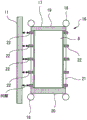
Fig. 4 is a front view of the car 8 of embodiment 1.
The displacement suppression device 16 is provided in the car 8. The car 8 includes a car frame 17 and a plurality of guide shoes 18.
The car frame 17 includes an upper beam 19, a lower beam 20, and a pair of vertical pillars 21. The upper beam 19 is disposed above the car 8 so as to extend between the left and right ends. For example, the main rope 7 is attached to the upper beam 19. The lower beam 20 is disposed at a lower portion of the car 8 so as to extend between the left and right end portions. The pair of vertical columns 21 are members disposed so as to span between the upper beam 19 and the lower beam 20. One vertical column 21 is disposed at the left end of the car 8. The other vertical column 21 is disposed at the right end of the car 8. The left vertical pillar 21 is disposed along the left car guide rail 11 of the car 8. The right vertical column 21 is disposed along the right car guide rail 11 of the car 8.
The guide shoes 18 are portions guided by the pair of car guide rails 11. Each guide shoe 18 faces an arbitrary car guide rail 11. Each guide shoe 18 is attached to the car frame 17, for example. Each guide shoe 18 is disposed at, for example, a left end portion or a right end portion of the upper beam 19 or the lower beam 20.
The displacement suppressing device 16 includes a plurality of stoppers 22. Each stopper 22 is a portion that restricts displacement of the car 8 by the car guide rail 11. The respective stoppers 22 are, for example, the same shape as each other. Each stopper 22 is attached to any of the vertical columns 21. The vertical columns 21 are provided with stoppers 22, for example, of the same number. In each vertical column 21, a plurality of stoppers 22 are arranged at equal intervals in the vertical direction. In each vertical column 21, a plurality of stoppers 22 are disposed vertically symmetrically with respect to the central portion. As the plurality of stoppers 22, 5 stoppers 22 are attached to each vertical column 21. Further, an even number of stoppers 22 may be attached to each vertical column 21 as a plurality of stoppers 22. Further, any stopper 22 may be disposed outside the guide shoe 18 in the vertical direction. That is, the arbitrary stopper 22 may be disposed above the guide shoe 18 disposed on the upper side of the car 8 such as the upper sill 19 or below the guide shoe 18 disposed on the lower side of the car 8 such as the lower sill 20. In this case, the vertical column 21 may extend to the outside of the guide shoe 18 in the vertical direction. Alternatively, a support body that supports the stopper 22 outside the guide shoe 18 may be provided on the car 8.
The center of the car 8 is an example of the 1 st position. In the car 8, a position above the 1 st position is an example of the 2 nd position. In the car 8, a position above the 2 nd position is an example of the 3 rd position. In this example, the spacing between the 2 nd position and the 3 rd position is equal to the spacing between the 1 st position and the 2 nd position. In the car 8, a position vertically symmetrical with respect to the center portion from the 2 nd position is an example of a symmetrical position.
Each stopper 22 faces the surface of the car guide rail 11 with a gap. In addition, the size of the gap shown in fig. 5 and the like is exaggerated for the sake of explanation. The clearance between each stopper 22 and the surface of the car guide rail 11 is set according to the position of the car 8 where the stopper 22 is provided.
In this example, the stopper 22 disposed at the center portion is an example of the 1 st stopper disposed at the 1 st position. The stopper 22 adjacent to the stopper 22 disposed at the center is an example of the 2 nd stopper disposed at the 2 nd position. The stoppers 22 adjacent below the stopper 22 disposed at the central portion are examples of symmetrical stoppers disposed at symmetrical positions. The stopper 22 disposed uppermost in the car 8 is an example of the 3 rd stopper disposed at the 3 rd position.
The 1 st stopper faces the surface of the car guide rail 11 with a 1 st gap. The 2 nd stopper faces the surface of the car guide rail 11 with a 2 nd gap. The 3 rd stopper is opposed to the surface of the car guide rail 11 with a 3 rd gap. The 2 nd gap is a gap larger than the 1 st gap. The 3 rd gap is a larger gap than the 2 nd gap.
Fig. 5 is a horizontal cross-sectional view of the car 8 of embodiment 1.
Fig. 5 shows a cross-sectional view taken along a horizontal plane passing through the center of the car 8.
Each of the vertical pillars 21 is provided at the center in the front-rear direction at the left and right end portions of the car 8.
Each stopper 22 faces each of the front surface, the rear surface, and the left and right inner side surfaces of the car guide rail 11. Here, the left and right inner side surfaces are the side surfaces on the car 8 side.
Fig. 6 is a horizontal sectional view of the stopper 22 of embodiment 1.
Fig. 6 shows a cross-sectional view taken along a horizontal plane passing through any stopper 22 as a representative.
In each stopper 22, the size of the gap between the front surface of the car guide rail 11 and the stopper 22 is smaller than the size of the gap between the left and right inner surfaces of the car guide rail 11 and the stopper 22. The size of the gap between the rear surface of the car guide rail 11 and the stopper 22 is smaller than the size of the gap between the left and right inner surfaces of the car guide rail 11 and the stopper 22.
In each stopper 22, the size of the gap between the front surface of the car guide rail 11 and the stopper 22 is equal to the size of the gap between the rear surface of the car guide rail 11 and the stopper 22. In the stoppers 22 arranged at the same height on the left and right vertical pillars 21, the gaps between the left and right inner surfaces of the car guide rail 11 and the stoppers 22 are equal to each other in size.
In addition, the offset load in the car 8 may occur regardless of the user or the weight carried in by the user. An offset load in the car 8 may be generated by roping of the main ropes 7 or the like, for example. Alternatively, an offset load in the car 8 may be generated by, for example, a positional deviation of the installation control cables or the compensating ropes. In this case, the size of the gap between the front surface of the car guide rail 11 and the stopper 22 may be different from the size of the gap between the rear surface of the car guide rail 11 and the stopper 22. In the stoppers 22 arranged at the same height in each of the left and right vertical pillars 21, the sizes of the gaps between the left and right inner surfaces of the car guide rail 11 and the stoppers 22 may be different from each other.
Fig. 7 is a diagram showing an example of the gap in the displacement reducing device 16 according to embodiment 1.
In fig. 7, the vertical axis indicates the position in the vertical direction in the car 8. In fig. 7, the horizontal axis indicates the size of the gap between the car guide rail 11 and the stopper 22. In fig. 7, a relationship between a gap between the front surface of the car guide rail 11 and the stopper 22 and a position of the stopper 22 in the up-down direction in the car 8 is shown.
In the car 8, the difference between the gap between the stoppers 22 disposed at positions separated from the central portion and the gap between the stoppers 22 disposed at the central portion is proportional to the distance from the central portion. The distance from the center portion is, for example, an absolute value of a height difference from the center portion. That is, the sizes of the 1 st gap, the 2 nd gap, and the 3 rd gap are related to each other by a 1 st order function of distance from the center portion of the car 8, for example. Further, as shown in fig. 7, the relationship between the clearance of the front surface of the car guide rail 11 and the stopper 22 and the position of the stopper 22 in the up-down direction in the car 8 is a symmetric relationship with respect to the central portion.
In this example, the relationship between the clearance between the rear surface of the car guide rail 11 and the stopper 22 and the position of the stopper 22 in the vertical direction in the car 8 is also the same as the relationship shown in fig. 7. The relationship between the gap between the left and right inner surfaces of the car guide rail 11 and the stopper 22 and the position of the stopper 22 in the vertical direction in the car 8 is also the same as that shown in fig. 7.
By having a plurality of stoppers 22 with such gaps set, the displacement suppression device 16 can suppress displacement of the upper portion of the car 8 or the lower portion of the car 8 even when the car 8 is inclined by an offset load. Thus, the displacement suppression device 16 can stably suppress displacement of the car 8 due to shaking caused by an earthquake or the like even when the car 8 is inclined by an offset load.
Fig. 8 and 9 are diagrams showing examples of the offset load in the car 8 of embodiment 1.
In fig. 8 and 9, the car 8 is shown as viewed from above.
In fig. 8, an offset load in the left-right direction is generated. When an offset load in the left-right direction occurs, the car 8 is inclined in the left-right direction. In this case, the displacement inhibitor 16 inhibits the displacement of the car 8 caused by the sway or the like by one of the left and right car guide rails 11.
On the other hand, in fig. 9, an offset load in the front-rear direction is generated. When an offset load in the front-rear direction occurs, the car 8 tilts in the front-rear direction. At this time, the displacement suppression device 16 suppresses displacement of the car 8 caused by sway or the like by both the left and right car guide rails 11. Therefore, the clearance between the surface of the car guide rail 11 and the stopper 22 for suppressing the displacement in the front-rear direction can be made smaller than the clearance between the surface of the car guide rail 11 and the stopper 22 for suppressing the displacement in the left-right direction.
The displacement inhibitor 16 may include a member that continuously connects end portions on the side facing the car guide rail 11 in the vertical direction between the 1 st stopper and the 2 nd stopper, for example. Alternatively, in the displacement inhibitor 16, a part or all of the plurality of stoppers 22 may be a part of a member provided continuously in the vertical direction to the vertical column 21.
The displacement suppressing device 16 may be provided in the counterweight 9 as the vertically movable body. In this case, the displacement suppression device 16 provided in the counterweight 9 functions in the same manner as the displacement suppression device 16 provided in the car 8, thereby suppressing the displacement of the counterweight 9. An offset load in the counterweight 9 may be generated by roping of the main ropes 7 or the like, for example. Alternatively, an offset load in the counterweight 9 may be generated, for example, by an offset of the position where the compensating ropes are installed.
As described above, the displacement suppressing device 16 for the vertically movable body according to embodiment 1 includes the 1 st stopper and the 2 nd stopper. The elevator body travels along the guide rails of the elevator 1. The 1 st stopper is provided at the 1 st position of the elevating body. The 1 st stopper is opposed to the guide rail with a 1 st gap. The 2 nd stopper is provided at the 2 nd position of the elevating body. The 2 nd position is farther from the center of the elevating body than the 1 st position in the vertical direction. The 2 nd stopper is opposed to the guide rail with a 2 nd gap. The 2 nd gap is larger than the 1 st gap.
With such a configuration, even when the vertically movable body is inclined by an offset load, the displacement suppressing device 16 can suppress a displacement in the horizontal direction due to shaking or the like of the upper portion or the lower portion displaced more largely than the central portion of the vertically movable body due to the inclination. Thus, the displacement suppression device 16 can stably suppress the displacement of the vertically movable body due to the shake of the earthquake or the like even when the vertically movable body is inclined by the offset load. That is, since the displacement due to the offset load is smaller at the 1 st position than at the 2 nd position and the 1 st gap is smaller than the 2 nd gap, the displacement of the vertically movable body due to the shake of the earthquake or the like can be stably suppressed. Further, since the 2 nd clearance is larger than the 1 st clearance at the 2 nd position where the displacement by the offset load is larger than the 1 st position, even when the vertically movable body is inclined by the offset load, the contact between the 2 nd stopper and the guide rail in the normal operation can be suppressed. This can suppress the occurrence of abnormal noise, vibration, impact, or the like due to the contact between the guide rail and the stopper 22. Therefore, the comfort of the user riding in the car 8 is not easily impaired. Therefore, the displacement suppression device 16 can suppress displacement of the vertically movable body due to vibration such as an earthquake and suppress contact between the guide rail and the stopper 22 during normal operation, even when the vertically movable body is inclined by an offset load.
Further, the displacement suppressing device 16 is provided with a symmetrical stopper. The symmetrical stopping pieces are arranged at symmetrical positions of the lifting body. The symmetrical position is a position symmetrical to the 2 nd position with respect to the central portion of the elevating body in the up-down direction. The symmetrical stoppers are opposed to the guide rail with a gap of the same size as the No. 2 gap.
With such a configuration, even when one of the upper and lower portions is displaced so as to approach the guide rail due to an inclination caused by an offset load, the displacement suppression device 16 can stably suppress displacement of the vertically movable body due to shaking caused by an earthquake or the like.
Further, the displacement suppressing device 16 includes a 3 rd stopper. The 3 rd stopper is disposed at the 3 rd position. The 3 rd position is farther from the center of the vertically movable body than the 2 nd position in the vertical direction. The 3 rd stopper is opposed to the guide rail with a 3 rd gap. The 3 rd gap is larger than the 2 nd gap. The size of the 1 st gap, the size of the 2 nd gap, and the size of the 3 rd gap are related to each other by a 1 st order function of distance from the central portion.
With such a configuration, the displacement suppressing device 16 can suppress displacement of the vertically movable body due to shaking or the like along the surface of the linear guide rail. Therefore, the displacement suppressing device 16 can suppress displacement of the vertically movable body due to vibration of an earthquake or the like more stably.
The 1 st stopper faces each of the front surface, the rear surface, and the left and right inner side surfaces of the guide rail. The 2 nd stopper faces each of the front surface, the rear surface, and the left and right inner side surfaces of the guide rail. The 2 nd gap with the front surface of the guide rail is larger than the 1 st gap with the front surface of the guide rail. The 2 nd gap with the rear surface of the guide rail is larger than the 1 st gap with the rear surface of the guide rail. The No. 2 clearance between the right and left inner side surfaces of the guide rail is larger than the No. 1 clearance between the right and left inner side surfaces of the guide rail.
With this configuration, the displacement of the vertically movable body is suppressed from 3 directions by the guide rail. This can suppress the displacement more stably.
At least one of the 1 st gap between the guide rail and the front surface and the 1 st gap between the guide rail and the rear surface is smaller than the 1 st gap between the guide rail and the inner side surface.
At least one of the 2 nd gap with the front surface of the guide rail and the 2 nd gap with the rear surface of the guide rail is smaller than the 2 nd gap with the inner side surface of the guide rail.
In such a configuration, the size of the gap for suppressing displacement is adjusted according to the degree of easy inclination of the vertically movable body. Therefore, it is possible to avoid a situation in which the displacement cannot be sufficiently suppressed due to an excessively large gap. Further, it is possible to avoid the stopper 22 from contacting the guide rail due to an excessively small clearance. This can suppress the occurrence of abnormal noise, vibration, impact, or the like due to the contact between the guide rail and the stopper 22. Therefore, the comfort of the user riding on the car 8 is not easily impaired.
The plurality of stoppers 22 arranged in the vertical direction in the vertically movable body such as the car 8 may be arranged at unequal intervals. For example, the plurality of stoppers 22 may be arranged such that the distance from the central portion of the vertically movable body decreases as the distance from the stopper decreases. In this case, the stopper 22 disposed above the central portion has a smaller vertical interval from the stopper 22 adjacent to the upper side than the vertical interval from the stopper 22 adjacent to the lower side. Further, with respect to the stoppers 22 arranged below the central portion, the vertical interval between the stoppers 22 adjacent on the lower side is smaller than the vertical interval between the stoppers 22 adjacent on the upper side.
Since the upper end portion of the vertical column 21 is connected to the upper beam 19 and the lower end portion of the vertical column 21 is connected to the lower beam 20, the horizontal rigidity of the vertical column 21 increases as the distance from the center portion increases. In the position where the rigidity is high, the vertical column 21 is not easily deformed even if the stopper 22 receives a reaction force from the guide rail. Since the vertical column 21 is less likely to be deformed so as to be detached from the guide rail, the effect of suppressing the displacement of the vertically movable body is less likely to be reduced in the stopper 22 provided at a position having a high rigidity. Therefore, the plurality of stoppers 22 arranged to be denser as the distance from the center portion increases can effectively suppress the displacement of the vertically movable body at a position where the rigidity of the vertical column 21 increases.
In embodiment 2, points different from the example disclosed in embodiment 1 will be described in particular detail. As for the features not described in embodiment 2, any features of the example disclosed in embodiment 1 may be adopted.
Fig. 10 is a diagram showing an example of inclination due to an offset load in the car 8 of embodiment 2.
In fig. 10, the car 8 is shown as viewed from the front.
When the car 8 is inclined by an offset load, the car guide rail 11 may be deformed such as bent by a reaction force from the car 8.
Fig. 11 is a diagram showing an example of displacement caused by an offset load in the car 8 of embodiment 2.
In fig. 11, the vertical axis indicates the position in the vertical direction in the car 8. In fig. 11, the horizontal axis represents the displacement of the car 8 in the horizontal direction due to an offset load and the displacement due to deformation of the car guide rail 11.
The clearance between the car guide rail 11 and the stopper 22 varies depending on the difference between the displacement caused by the inclination of the car 8 and the displacement caused by the deformation of the car guide rail 11 due to the inclination. Here, the car guide rail 11 may be curved in the vertical direction.
Fig. 12 is a diagram illustrating an example of the gap in the displacement suppressing device 16 according to embodiment 2.
In fig. 12, the vertical axis indicates the position in the vertical direction in the car 8. In fig. 12, the horizontal axis indicates the size of the gap between the car guide rail 11 and the stopper 22. In fig. 12, a relationship between a gap between the front surface of the car guide rail 11 and the stopper 22 and a position of the stopper 22 in the up-down direction in the car 8 is shown.
In the car 8, the difference in the magnitude between the gap between the stopper 22 disposed at a position away from the central portion and the gap between the stoppers 22 disposed at the central portion follows a monotonically increasing function of the distance from the central portion. Here, the function is a nonlinear function that is set in advance in accordance with the inclination of the car 8 due to the offset load and the amount of deformation of the car guide rail 11 due to the inclination. The function is, for example, a convex function or a concave function relating to the distance from the central portion. That is, when the displacement inhibitor 16 has the 1 st stopper, the 2 nd stopper, and the 3 rd stopper, the sizes of the 1 st gap, the 2 nd gap, and the 3 rd gap are related to the distance from the center of the car 8 according to the function.
In this example, the relationship between the clearance between the rear surface of the car guide rail 11 and the stopper 22 and the position of the stopper 22 in the vertical direction in the car 8 may be the same as the relationship shown in fig. 12. The relationship between the gap between the left and right inner surfaces of the car guide rail 11 and the stopper 22 and the position of the stopper 22 in the vertical direction of the car 8 may be the same as that shown in fig. 12.
As described above, the displacement suppressing device 16 according to embodiment 2 includes the 3 rd stopper. The 3 rd stopper is disposed at the 3 rd position. The 3 rd position is farther from the center of the vertically movable body than the 2 nd position in the vertical direction. The 3 rd stopper is opposed to the guide rail with a 3 rd gap. The 3 rd gap is larger than the 2 nd gap. The size of the 1 st gap, the size of the 2 nd gap, and the size of the 3 rd gap are related to each other as a function of distance from the central portion. The function is a nonlinear function based on the inclination due to the offset load of the elevating body and the amount of deformation of the guide rail due to the inclination.
In such a configuration, the displacement suppressing device 16 can suppress displacement of the vertically movable body due to vibration or the like in consideration of deformation of the guide rail. Therefore, the displacement suppression device 16 can stably suppress the displacement of the vertically movable body due to the shake of the earthquake or the like even when the guide rail is deformed.
In embodiment 3, a point different from the example disclosed in embodiment 1 or embodiment 2 will be described in particular detail. As for the features not described in embodiment 3, any of the features of the examples disclosed in embodiment 1 or embodiment 2 may be employed.
Fig. 13 is a plan view of the stopper 22 according to embodiment 3.
In fig. 13, the stopper 22 is shown as viewed from above.
In the displacement inhibitor 16, the plurality of stoppers 22 including the 1 st stopper, the 2 nd stopper, the 3 rd stopper, the symmetrical stopper, and the like are each provided with 1 or more sets of the shoe 23 and the actuator 24. In this example, the stopper 22 includes 3 sets of shoes 23 and actuators 24. In any 1 of the 3 sets, the shoe 23 is opposed to the front surface of the car guide rail 11. In the other of the 3 groups, the shoe 23 is opposed to the rear surface of the car guide rail 11. In the remaining 1 of the 3 groups, the shoes 23 face the left and right inner side surfaces of the car guide rail 11. In each group, the actuator 24 changes the gap between the car guide rail 11 and the shoe 23 by moving the shoe 23. In addition, in some or all of the plurality of stoppers 22, any 1 group or any 2 groups of the group of the shoe 23 and the actuator 24 may be omitted.
The shoes 23 of each set in the 1 st stop are examples of the 1 st shoe. The car guide rail 11 is opposed to the 1 st shoe with a 1 st gap. The actuators 24 of each group in the 1 st stop are examples of the 1 st actuator. The shoes 23 of each set in the 2 nd stop are examples of the 2 nd shoe. The car guide rail 11 is opposed to the 2 nd shoe with a 2 nd gap. Each set of actuators 24 in the 2 nd stop is an example of a 2 nd actuator.
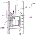
Fig. 14 is a configuration diagram of a displacement suppression device 16 according to embodiment 3.
In fig. 14, the car 8 is shown as viewed from the front.
In the car 8, a weighing device 25 is provided. The weighing device 25 is provided at a lower portion of the car 8. The weighing device 25 is an example of an offset load measuring unit that measures an offset load in the car 8. The weighing device 25 is provided with a function of outputting the measured offset load to an external device.
The displacement suppression device 16 includes a control unit 26. The control unit 26 controls the operation of the actuator 24 in each stopper 22. The control unit 26 is provided, for example, on the upper part of the car 8. Alternatively, the control unit 26 may be mounted on the control panel 15 of the elevator 1, for example. Alternatively, the displacement suppressing device 16 may include independent control units 26 corresponding to the stoppers 22 one by one. Alternatively, the displacement suppression device 16 may include independent control units 26 corresponding to the respective actuators 24 one by one. The control unit 26 is connected to an offset load measuring unit such as the weighing device 25 so as to obtain a measurement result of the offset load of the car 8.
Next, an operation example of the displacement inhibitor 16 will be described.
In normal operation, the weighing device 25 measures the offset load in the car 8. The weighing device 25 outputs the measured offset load to the control unit 26.
The control unit 26 calculates the inclination of the car 8 from the offset load input from the weighing device 25. The control unit 26 calculates a change in the clearance between each stopper 22 and the car guide rail 11 based on the calculated inclination of the car 8. The control unit 26 operates the actuators 24 so that the gaps between the stoppers 22 and the car guide rail 11 are narrowed within a predetermined range in accordance with the calculated change in the gaps. This range is set in advance so that the displacement of the car 8 during shaking due to an earthquake or the like can be suppressed by the car guide rail 11.
On the other hand, during the earthquake time control operation, the actuators 24 maintain the gaps between the car guide rail 11 and the shoes 23 in a narrow state regardless of the measurement result of the offset load by the weighing device 25. Thereby, the displacement of the car 8 due to the shake of the earthquake or the like is suppressed by the car guide rail 11.
In addition, the car 8 may be provided with a not-shown inclination measuring unit. The inclination measuring portion is a portion that measures the inclination of the car 8. The inclination measuring unit is disposed, for example, on the upper or lower portion of the car 8. The inclination measurement unit includes, for example, an inclination sensor, an acceleration sensor, a gyro sensor, and the like. The inclination measuring unit is equipped with a function of outputting the result of measuring the inclination of the car 8.
During normal operation, the control unit 26 calculates a change in the clearance between each stopper 22 and the car guide rail 11 based on the inclination of the car 8 input from the inclination measuring unit. The control unit 26 operates the actuators 24 in accordance with the calculated change in the gap so that the gap between the shoe 23 of each stopper 22 and the car guide rail 11 is narrowed within a predetermined range.
On the other hand, during the earthquake time control operation, the actuators 24 maintain the gaps between the car guide rail 11 and the shoes 23 in a narrow state regardless of the measurement result of the inclination by the inclination measuring unit. Thereby, displacement of the car 8 due to shaking of an earthquake or the like is suppressed by the car guide rail 11.
In the car 8, a load cell such as a load cell not shown may be provided. The load meter is provided on at least one of the guide shoes 18, for example. A load cell is a device that measures the horizontal reaction force from the car guide rail 11 to which the guide shoe 18 is subjected. Since the horizontal reaction force applied to the guide shoe 18 depends on the inclination of the car 8, the inclination of the entire car frame 17 is measured by a load cell. That is, the load meter functions as another example of the inclination measuring unit. Since the inclination of the entire car frame 17 is measured by the load system, it is possible to measure the inclination caused by, for example, positional deviation of the control cable or the compensating rope with high accuracy.
Fig. 15 is a configuration diagram of a displacement suppression device 16 according to modification 1 of embodiment 3.
In fig. 15, the car 8 is shown as viewed from the front.
In the car 8, a camera 27 is provided. The camera 27 is disposed inside the car 8. The camera 27 calculates the offset load in the car 8 by image recognition of the captured internal image of the car 8 or the like. In this example, the camera 27 is an example of an offset load measuring unit that measures an offset load in the car 8. The control unit 26 calculates the inclination of the car 8 based on information of the offset load input from the camera 27 as an example of the offset load measuring unit. The control unit 26 operates the actuators 24 in accordance with the calculated inclination of the car 8.
Fig. 16 is a configuration diagram of a displacement suppression device 16 according to modification 2 of embodiment 3.
In fig. 16, the stopper 22 is shown as viewed from above.
The displacement suppression device 16 includes a gap measurement unit 28. The clearance measuring portion 28 is a portion that measures the clearance between the car guide rail 11 and the stopper 22. The gap measuring unit 28 measures the gap of at least one stopper 22 of the plurality of stoppers 22 including the 1 st stopper, the 2 nd stopper, the 3 rd stopper, the symmetrical stopper, and the like. In this example, the gap measuring unit 28 measures the gap between the 1 st stopper and the 2 nd stopper.
The gap measuring unit 28 includes a plurality of distance sensors 29. In this example, 2 distance sensors 29 correspond to the 1 st stopper. One distance sensor 29 measures a gap between the shoe 23 facing the front surface of the car guide rail 11 and the front surface. The other distance sensor 29 measures a gap between the shoe 23 facing the left and right inner side surfaces of the car guide rail 11 and the inner side surface. The plurality of distance sensors 29 of the gap measuring unit 28 include 2 distance sensors 29 that similarly measure the gap corresponding to the 2 nd stopper. The gap measuring unit 28 outputs the size of each gap measured by the plurality of distance sensors 29 to the control unit 26.
The control unit 26 operates the actuators 24 so that the gaps between the shoes 23 of the stoppers 22 and the car guide rails 11 are narrowed within a predetermined range according to the magnitude of the gap input from the gap measuring unit 28. The control unit 26 may estimate the magnitude of the gap between the shoe 23 facing the rear surface of the car guide rail 11 and the rear surface of the car guide rail 11 from, for example, a measurement value of the magnitude of the gap between the shoe 23 facing the front surface of the car guide rail 11 and the front surface at least at any one of the stoppers 22. At this time, the control unit 26 operates the actuators 24 so that the gaps between the shoes 23 of the stoppers 22 and the car guide rails 11 are narrowed within a predetermined range according to the estimated magnitude of the gaps. The control unit 26 may estimate the inclination of the car 8 based on the size of the gap measured by the distance sensor 29 provided at any stopper 22. At this time, the control unit 26 operates each actuator 24 based on the estimated inclination. Here, the controller 26 may operate the actuators 24 in accordance with the estimated inclination of the stopper 22 whose gap measuring unit 28 does not measure the size of the gap.
On the other hand, during the earthquake time control operation, the actuators 24 maintain the clearances between the car guide rail 11 and the shoes 23 in a narrow state regardless of the measurement results of the clearances by the clearance measurement portions 28. Thereby, the displacement of the car 8 due to the shake of the earthquake or the like is suppressed by the car guide rail 11.
In addition, control cables, compensation ropes, and the like attached to the car 8 vary depending on the position of the car 8. Therefore, for example, when an offset load occurs in the car 8 due to a deviation in the position where the control cable or the like is attached, the offset load of the car 8 similarly varies depending on the position of the car 8. In this case, the control unit 26 may estimate the offset load or inclination of the car 8, the gap between the car guide rail 11 and the stopper 22, or the like, based on the position of the car 8. The control unit 26 operates the actuators 24 based on the result of estimation by the position of the car 8.
When the displacement inhibitor 16 is provided in the counterweight 9 as the ascending/descending body, a wire may be connected to the counterweight 9 and the wire may supply power and communicate signals to the displacement inhibitor 16. Alternatively, the counterweight 9 may be equipped with a battery or the like that supplies electric power to the displacement suppression device 16. The displacement suppressing device 16 may receive power supply and signal communication by wireless, for example.
As described above, in the displacement suppressing device 16 according to embodiment 3, the 1 st stopper includes the 1 st shoe and the 1 st actuator. The 1 st shoe is opposed to the guide rail with a 1 st gap. The 1 st actuator changes the size of the 1 st gap by moving the 1 st shoe. The 2 nd stopper is provided with a 2 nd shoe and a 2 nd actuator. The 2 nd shoe is opposed to the guide rail with a 2 nd gap. The 2 nd actuator changes the size of the 2 nd gap by moving the 2 nd shoe.
In such a configuration, the size of the gap is variable depending on the position of the vertically movable body, the state of the offset load, the inclination, or the like, and therefore the size of the gap can be adjusted during normal operation so as not to interfere with the traveling of the vertically movable body or the like. Thus, even when the state of the vertically movable body changes due to a load, such as an offset load, due to the entrance and exit of a user, the displacement of the vertically movable body due to the earthquake shake can be suppressed according to the changed state of the vertically movable body.
Further, the offset load measuring unit measures an offset load of the lifting body. The 1 st actuator changes the size of the 1 st gap according to the inclination of the ascending/descending body caused by the offset load measured by the offset load measuring unit. The 2 nd actuator changes the size of the 2 nd gap according to the inclination of the ascending/descending body due to the offset load measured by the offset load measuring unit.
Further, the inclination measuring section measures the inclination of the elevating body. The 1 st actuator changes the size of the 1 st gap according to the inclination of the ascending/descending body measured by the inclination measuring unit. The 2 nd actuator changes the size of the 2 nd gap according to the inclination of the elevating body measured by the inclination measuring unit.
The displacement suppression device 16 is also provided with a gap measurement unit 28. The gap measuring unit 28 measures the size of at least one of the 1 st gap and the 2 nd gap. The 1 st actuator changes the size of the 1 st gap according to the size of the gap measured by the gap measuring unit 28. The 2 nd actuator changes the size of the 2 nd gap according to the size of the gap measured by the gap measuring section 28.
In such a configuration, since the size of the gap is variable according to the state of the vertically movable body which is actually measured, the size of the gap can be adjusted with higher accuracy in the normal operation. In particular, when the gap between the guide rail and the stopper 22 is measured, the size of the gap can be adjusted in accordance with the state of deformation of the guide rail.
Next, an example of the hardware configuration of the displacement suppression device 16 will be described with reference to fig. 17.
Fig. 17 is a hardware configuration diagram of a main part of a displacement suppression device 16 according to embodiment 3.
The functions of the displacement suppression means 16 may be implemented by processing circuitry. The processing circuit is provided with at least 1 processor 100a and at least 1 memory 100b. The processing circuit may also be provided with at least one dedicated hardware 200 in addition to the processor 100a and the memory 100b or instead of the processor 100a and the memory 100b.
When the processing circuit includes the processor 100a and the memory 100b, each function of the displacement suppression device 16 is realized by software, firmware, or a combination of software and firmware. At least one of the software and the firmware is described as a program. The program is stored in the memory 100b. The processor 100a realizes each function of the displacement suppressing device 16 by reading out and executing a program stored in the memory 100b.
The processor 100a is also called a CPU (Central Processing Unit), a Processing device, an arithmetic device, a microprocessor, a microcomputer, or a DSP. The Memory 100b is configured by a nonvolatile or volatile semiconductor Memory such as a RAM (Random Access Memory), a ROM (Read Only Memory), a flash Memory, an EPROM (Erasable Programmable Read Only Memory), an EEPROM (Electrically Erasable Programmable Read Only Memory), or the like.
When the processing Circuit includes the dedicated hardware 200, the processing Circuit is realized by, for example, a single Circuit, a composite Circuit, a programmed processor, a parallel programmed processor, an ASIC (Application Specific Integrated Circuit), an FPGA (Field Programmable Gate Array), or a combination thereof.
The respective functions of the displacement suppressing means 16 may be realized by the processing circuit, respectively. Alternatively, the functions of the displacement suppression device 16 may be realized collectively by a processing circuit. The functions of the displacement suppressing device 16 may be partially implemented by dedicated hardware 200, and the other parts may be implemented by software or firmware. In this way, the processing circuitry implements the functions of the displacement suppression means 16 by dedicated hardware 200, software, firmware, or a combination thereof.
Industrial applicability
The displacement suppression device of the present invention can be applied to an elevator body of an elevator.
Description of the reference symbols
1: an elevator; 2: a building; 3: a hoistway; 4: a machine room; 5: a pit; 6: a traction machine; 7: a main rope; 8: a car; 9: a counterweight; 10: a car door; 11: a car guide rail; 12: a counterweight guide rail; 13: a bracket; 14: a seismic detector; 15: a control panel; 16: a displacement restraint device; 17: a car frame; 18: a guide shoe; 19: an upper beam; 20: a lower beam; 21: a longitudinal column; 22: a stopper; 23: a boot; 24: an actuator; 25: a weighing device; 26: a control unit; 27: a camera; 28: a gap measuring section; 29: a distance sensor; 100a: a processor; 100b: a memory; 200: dedicated hardware.
Claims (12)
1. A displacement suppression device for a vertically movable body of an elevator, comprising:
a 1 st stopper provided at a 1 st position of a lifting body traveling along a guide rail of an elevator, and facing the guide rail with a 1 st gap; and
and a 2 nd stopper provided at a 2 nd position of the vertically movable body and facing the guide rail with a 2 nd gap larger than the 1 st gap, the 2 nd position being farther from a central portion of the vertically movable body than the 1 st position in a vertical direction.
2. The displacement suppressing device of the elevating body of an elevator according to claim 1,
the displacement suppressing device for the vertically movable body of the elevator includes a symmetrical stopper provided at a symmetrical position of the vertically movable body which is symmetrical with the 2 nd position with respect to a central portion of the vertically movable body, and facing the guide rail with a gap having the same size as the 2 nd gap.
3. The displacement suppressing device of a lifting body of an elevator according to claim 1 or 2,
the displacement suppressing device for the vertically movable body of the elevator comprises a 3 rd stopper which is provided at a 3 rd position of the vertically movable body and faces the guide rail with a 3 rd gap larger than the 2 nd gap, the 3 rd position being further away from a central portion of the vertically movable body than the 2 nd position in the vertical direction,
the size of the 1 st gap, the size of the 2 nd gap, and the size of the 3 rd gap are related to each other by a 1 st order function of distance from the central portion.
4. The displacement suppressing device of a lifting body of an elevator according to claim 1 or 2,
the displacement suppressing device for the vertically movable body of the elevator comprises a 3 rd stopper which is provided at a 3 rd position of the vertically movable body and faces the guide rail with a 3 rd gap larger than the 2 nd gap, the 3 rd position being further away from a central portion of the vertically movable body than the 2 nd position in the vertical direction,
the size of the 1 st gap, the size of the 2 nd gap, and the size of the 3 rd gap are related to each other by a nonlinear function based on an inclination due to a bias load of the vertically movable body and a deformation amount of the guide rail due to the inclination.
5. The displacement suppressing device of the elevating body of the elevator according to any one of claims 1 to 4, wherein,
the displacement suppressing device for the elevator lifting body comprises a plurality of stoppers including the 1 st stopper and the 2 nd stopper,
the plurality of stoppers are arranged in a vertical direction on the lifting body, and are configured so that the distance between the stoppers and the adjacent stoppers in the vertical direction decreases as the distance from the central part of the lifting body increases.
6. The displacement suppressing device of the elevating body of the elevator according to any one of claims 1 to 5, wherein,
the 1 st stopper includes:
a 1 st shoe opposed to the guide rail with the 1 st gap therebetween; and
a 1 st actuator to change a size of the 1 st gap by moving the 1 st shoe,
the 2 nd stopper includes:
a 2 nd shoe opposed to the guide rail with the 2 nd gap therebetween; and
a 2 nd actuator to change a size of the 2 nd gap by moving the 2 nd shoe.
7. The displacement suppressing device of a lifting body of an elevator according to claim 6,
the 1 st actuator changes the size of the 1 st gap according to the inclination of the ascending/descending body caused by the offset load measured by the offset load measuring unit that measures the offset load of the ascending/descending body,
the 2 nd actuator changes the size of the 2 nd gap according to the inclination of the ascending/descending body due to the offset load measured by the offset load measuring unit.
8. The displacement suppressing device of a lifting body of an elevator according to claim 6,
the 1 st actuator changes the size of the 1 st gap according to the inclination of the lifting body measured by an inclination measuring unit that measures the inclination of the lifting body,
the 2 nd actuator changes the size of the 2 nd gap according to the inclination of the lifting body measured by the inclination measuring unit.
9. The displacement suppressing device of a lifting body of an elevator according to claim 6,
the displacement suppressing device for the elevating body of the elevator comprises a gap measuring part for measuring the size of at least one of the 1 st gap and the 2 nd gap,
the 1 st actuator changes the size of the 1 st gap according to the size of the gap measured by the gap measuring part,
the 2 nd actuator changes the size of the 2 nd gap according to the size of the gap measured by the gap measuring unit.
10. The displacement suppressing device of a lifting body of an elevator according to any one of claims 1 to 9,
the 1 st stopper is opposed to each of three faces of a front surface, a rear surface, and left and right inner side faces of the guide rail,
the 2 nd stopper is opposed to each of three faces of a front surface, a rear surface, and left and right inner side faces of the guide rail,
the 2 nd gap with the front surface of the guide rail is larger than the 1 st gap with the front surface of the guide rail,
the 2 nd gap with the rear surface of the guide rail is larger than the 1 st gap with the rear surface of the guide rail,
the 2 nd gap with the left and right inner side surfaces of the guide rail is larger than the 1 st gap with the left and right inner side surfaces of the guide rail.
11. The displacement suppressing device of the elevating body of the elevator according to claim 10,
at least one of the 1 st gap with the front surface of the guide rail and the 1 st gap with the rear surface of the guide rail is smaller than the 1 st gap with the left and right inner side surfaces of the guide rail.
12. The displacement suppressing device of a lifting body of an elevator according to claim 10 or 11,
at least one of the 2 nd gap with the front surface of the guide rail and the 2 nd gap with the rear surface of the guide rail is smaller than the 2 nd gap with the left and right inner side surfaces of the guide rail.
Applications Claiming Priority (1)
| Application Number | Priority Date | Filing Date | Title |
|---|---|---|---|
| PCT/JP2020/026298 WO2022003984A1 (en) | 2020-07-03 | 2020-07-03 | Displacement suppression device for elevating body of elevator |
Publications (1)
| Publication Number | Publication Date |
|---|---|
| CN115803277A true CN115803277A (en) | 2023-03-14 |
Family
ID=79315011
Family Applications (1)
| Application Number | Title | Priority Date | Filing Date |
|---|---|---|---|
| CN202080102253.3A Pending CN115803277A (en) | 2020-07-03 | 2020-07-03 | Displacement suppressing device for elevating body of elevator |
Country Status (3)
| Country | Link |
|---|---|
| JP (1) | JP7435780B2 (en) |
| CN (1) | CN115803277A (en) |
| WO (1) | WO2022003984A1 (en) |
Family Cites Families (7)
| Publication number | Priority date | Publication date | Assignee | Title |
|---|---|---|---|---|
| JPS5440816B2 (en) * | 1974-05-22 | 1979-12-05 | ||
| JPS5110769U (en) * | 1974-07-12 | 1976-01-26 | ||
| JPS53131641A (en) * | 1977-04-19 | 1978-11-16 | Fujitec Co Ltd | Roller guide apparatus for elevator cage |
| JP2001139255A (en) | 1999-11-16 | 2001-05-22 | Otis Elevator Co | Elevator guide device |
| JP4052304B2 (en) | 2004-11-09 | 2008-02-27 | 株式会社日立製作所 | Elevator |
| JP5355291B2 (en) | 2009-08-07 | 2013-11-27 | 三菱電機株式会社 | Elevator guide shoe installation adjustment method |
| JP2015137170A (en) | 2014-01-23 | 2015-07-30 | 株式会社日立ビルシステム | Elevator device |
-
2020
- 2020-07-03 WO PCT/JP2020/026298 patent/WO2022003984A1/en active Application Filing
- 2020-07-03 JP JP2022533019A patent/JP7435780B2/en active Active
- 2020-07-03 CN CN202080102253.3A patent/CN115803277A/en active Pending
Also Published As
| Publication number | Publication date |
|---|---|
| WO2022003984A1 (en) | 2022-01-06 |
| JP7435780B2 (en) | 2024-02-21 |
| JPWO2022003984A1 (en) | 2022-01-06 |
Similar Documents
| Publication | Publication Date | Title |
|---|---|---|
| JP4252330B2 (en) | Elevator rope damping device | |
| JPH0388687A (en) | Elevator device | |
| EP3584208B1 (en) | Position reference device for elevator | |
| US7631731B2 (en) | Elevator | |
| US11383955B2 (en) | Elevator system control based on building and rope sway | |
| JP7148490B2 (en) | Elevator control method and control system | |
| KR20130143724A (en) | Double deck elevator | |
| JP6399404B2 (en) | Car roll restraining device and elevator roll restraining method for elevator | |
| CN115803277A (en) | Displacement suppressing device for elevating body of elevator | |
| JP3868789B2 (en) | Elevator equipment | |
| KR102135192B1 (en) | Elevator control device and control method | |
| JP7327670B2 (en) | Elevator lifting body displacement control device | |
| CN107021405A (en) | Elevator | |
| JP4761879B2 (en) | elevator | |
| JP6494793B2 (en) | Elevator and elevator operation method | |
| EP1512652A1 (en) | Elevator | |
| JP7047972B2 (en) | Elevator slip detection system | |
| JP2002003118A (en) | Elevator device | |
| CN108689274B (en) | Weighing device of elevator | |
| CN112512948B (en) | Health diagnostic device | |
| WO2023021651A1 (en) | Elevator car and elevator | |
| WO2024042642A1 (en) | Deformation detection system and deformation detection method for elevator guide rail | |
| WO2003078290A1 (en) | Elevator winch and elevator device | |
| CN110770154A (en) | Elevator device | |
| WO2020100306A1 (en) | Elevator |
Legal Events
| Date | Code | Title | Description |
|---|---|---|---|
| PB01 | Publication | ||
| PB01 | Publication | ||
| SE01 | Entry into force of request for substantive examination | ||
| SE01 | Entry into force of request for substantive examination |