WO2022003962A1 - 故障診断装置 - Google Patents
故障診断装置 Download PDFInfo
- Publication number
- WO2022003962A1 WO2022003962A1 PCT/JP2020/026230 JP2020026230W WO2022003962A1 WO 2022003962 A1 WO2022003962 A1 WO 2022003962A1 JP 2020026230 W JP2020026230 W JP 2020026230W WO 2022003962 A1 WO2022003962 A1 WO 2022003962A1
- Authority
- WO
- WIPO (PCT)
- Prior art keywords
- failure diagnosis
- temperature
- unit
- thermal image
- data
- Prior art date
- Legal status (The legal status is an assumption and is not a legal conclusion. Google has not performed a legal analysis and makes no representation as to the accuracy of the status listed.)
- Ceased
Links
Images



Classifications
-
- G—PHYSICS
- G01—MEASURING; TESTING
- G01D—MEASURING NOT SPECIALLY ADAPTED FOR A SPECIFIC VARIABLE; ARRANGEMENTS FOR MEASURING TWO OR MORE VARIABLES NOT COVERED IN A SINGLE OTHER SUBCLASS; TARIFF METERING APPARATUS; MEASURING OR TESTING NOT OTHERWISE PROVIDED FOR
- G01D21/00—Measuring or testing not otherwise provided for
Definitions
- This technology is related to failure diagnosis equipment. In particular, it is related to failure diagnosis of equipment used for equipment related to inspection.
- a contact-type temperature sensor is manually applied to a sensor to be diagnosed, the temperature is visually detected, and a sensor failure diagnosis is performed.
- a contact temperature sensor it is very troublesome to apply a contact temperature sensor to a sensor and compare the temperatures, especially when the number of sensors to be diagnosed is large.
- the temperature may be estimated from the state of the refrigerant, and the number of sensors in the air conditioner is decreasing. Therefore, there is a possibility that the failure diagnosis technique known as the prior art cannot be applied.
- the failure diagnosis technique known as the prior art cannot be applied.
- the failure diagnosis device is a failure diagnosis device that performs failure diagnosis of the object to be diagnosed possessed by the device to be inspected, and is a thermal image processing unit that processes thermal image data including the diagnostic object to derive the measured temperature. And, based on the control data used to control the device to be inspected, the control data processing unit that derives the temperature obtained from the control of the device to be inspected as the control temperature, and the data comparison that calculates the temperature difference between the measured temperature and the control temperature. It is provided with a unit and a failure diagnosis unit that performs a failure diagnosis of a diagnostic object based on the temperature difference calculated by the data comparison unit.
- the failure diagnosis unit has a temperature difference between the measured temperature obtained from the thermal image data including the diagnostic object and the control temperature obtained from the control data used to control the device to be inspected having the diagnostic object. Based on the above, failure diagnosis of the object to be diagnosed can be easily and efficiently performed.
- FIG. It is a figure which shows the configuration example of the air conditioning system 1 which has the failure diagnosis apparatus which concerns on Embodiment 1.
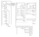
- FIG. It is a figure which shows the structure in each apparatus of the air conditioning system 1 which has the failure diagnosis apparatus which realizes the failure diagnosis of the object to be diagnosed which the inspected apparatus has.
- FIG. It is a figure explaining the flow of the process which concerns on the failure diagnosis performed by the server 100 which concerns on Embodiment 2.
- FIG. It is a figure explaining the positional relationship in the refrigerant circuit of the 1st electron expansion valve 350 in the air conditioner 200 which concerns on Embodiment 2.
- FIG. It is a figure explaining the flow of the process which concerns on the failure diagnosis performed by the server 100 which concerns on Embodiment 3.
- FIG. 1 is a diagram showing a configuration example of an air conditioning system 1 having a failure diagnosis device according to the first embodiment.
- the air conditioning system 1 of the first embodiment is configured by connecting a server 100, an air conditioning device 200, and an operation terminal device 500 so as to be communicable by a telecommunication line 600.
- the telecommunication line 600 may be not only a general public electric line but also a LAN (Local Area Network) or the like. Further, the telecommunication line 600 may be a wireless connection as well as a wired connection.
- the server 100 will be described as a failure diagnosis device.
- the server 100 is a sensor that processes various data included in signals transmitted from the air conditioner 200 and the operation terminal device 500 via the telecommunication line 600, and detects a physical quantity of the air conditioner 200 that is the device to be inspected. Performs failure diagnosis of diagnostic objects such as.
- a failure diagnosis using a temperature sensor that detects a temperature as a physical quantity as a diagnostic object will be described.
- the server 100 acquires data such as the temperature, humidity or weather of the outside air from devices other than the air conditioner 200 and the operation terminal device 500, and includes these data in the failure diagnosis. Processing may be performed.
- the air conditioner 200 of the first embodiment which is the device to be inspected, has an outdoor unit 300 and an indoor unit 400.
- the air conditioner 200 is a device that connects the devices in the outdoor unit 300 and the indoor unit 400 with pipes to form a refrigerant circuit, and circulates the refrigerant in the refrigerant circuit to perform air conditioning in the target space.
- the air conditioner 200 is not limited to this configuration.
- the air conditioner 200 may have a controller, a relay unit, and the like in addition to the outdoor units 300 and 400.
- the air conditioner 200 may circulate a heat medium such as water or brine, which is a fluid other than the refrigerant, in the connected pipe.
- the operation terminal device 500 is a terminal device operated by the user.
- the operation terminal device 500 of the first embodiment sends a signal including data obtained by processing input and imaging by the user to the server 100. Further, the operation terminal device 500 receives a signal including the failure diagnosis result data sent from the server 100, and notifies the user of the diagnosis result.
- the operation terminal device 500 is a device such as a personal computer or a smartphone, but the operation terminal device 500 is not limited thereto.
- the operation terminal device 500 may be an input terminal device such as a thermo camera capable of capturing a thermal image.
- FIG. 2 is a diagram showing a configuration in each device of an air conditioning system 1 having a failure diagnosis device that realizes a failure diagnosis of a diagnosis target possessed by the device to be inspected.
- the server 100 of the first embodiment is a failure diagnosis device for diagnosing whether or not a sensor or the like included in the air conditioner 200 has a failure. Therefore, the server 100 of the first embodiment includes a device information storage unit 110, a server-side data transmission / reception unit 120, and a data processing unit 130.
- the device information storage unit 110 has a storage device, and stores and stores data related to the air conditioner 200.
- the device information storage unit 110 records, stores, and stores data regarding each device of the outdoor unit 300 and the indoor unit 400 in the air conditioner 200 as device information 111.
- the device information 111 is data that can distinguish the same type of device such as a model name and a serial number with respect to the main body of the air conditioner 200.
- the device information storage unit 110 records, stores, and stores data related to the piping configuration as the piping configuration information 112 in association with the device information 111.
- the pipe configuration information 112 is data regarding the positions of pipes, sensors, actuators, and the like in the outdoor unit 300, the indoor unit 400, and the like in the air conditioner 200.
- the device information 111 and the piping configuration information 112 are used by the data processing unit 130 for processing to identify a diagnostic object included in the thermal image.
- the device information storage unit 110 does not have to store all the data from the beginning.
- the device information storage unit 110 may acquire and store data from another device such as the air conditioning device 200, another server, an air conditioning system, or the like.
- the device information storage unit 110 may store and store not only the data in the transmitted signal but also the data obtained by arithmetic processing in the server 100.
- the server-side data transmission / reception unit 120 serves as an interface for signal communication between the data processing unit 130, the air conditioning device 200, and the operation terminal device 500 via the telecommunication line 600.
- the communication of the server-side data transmission / reception unit 120 will be described as being performed between the air conditioner 200 and the operation terminal device 500, but the communication is performed with other devices and systems. You may.
- the data processing unit 130 performs a process of diagnosing whether or not the diagnostic object is out of order based on the data included in the signals sent from the air conditioner 200 and the operation terminal device 500.
- the data processing unit 130 of the first embodiment includes a data comparison unit 131, a failure diagnosis unit 132, a thermal image processing unit 133, a control data processing unit 134, and a result notification unit 135.
- the thermal image processing unit 133 processes the data related to the thermal image sent from the operation terminal device 500, identifies the diagnostic object contained in the thermal image, and acquires the measured temperature of the temperature sensor.
- the measured temperature is the actual temperature detected when the temperature sensor is normal.
- the thermal image processing unit 133 performs a process of acquiring the measured temperature from the thermal image
- the thermal image processing unit 133 performs a process using control data or the like provided from the air conditioner 200 described later to correct the measured temperature. May be good.
- the control data processing unit 134 requests the air conditioner 200 to provide control data regarding the diagnostic object specified by the thermal image processing unit 133. Then, as will be described later, the control data processing unit 134 performs a process of acquiring the control temperature from the control data in the signal sent from the air conditioner 200.
- the control data is data such as a control value used when controlling the device in the air conditioner 200 and a physical quantity value detected by various sensors used for calculating the control value.
- the control temperature is the temperature detected for the diagnostic object estimated from the control data from the air conditioner 200. When the object to be diagnosed is a temperature sensor, the temperature desired to be detected by the temperature sensor is the control temperature.
- the data comparison unit 131 calculates the temperature difference by comparing the measured temperature acquired by the thermal image processing unit 133 with the control temperature acquired by the control data processing unit 134.
- the failure diagnosis unit 132 performs a failure diagnosis of the object to be diagnosed based on the temperature difference calculated by the data comparison unit 131.
- the result notification unit 135 performs a process of notifying the diagnosis result by the failure diagnosis unit 132.
- the result notification unit 135 sends a signal including data related to the diagnosis result to the operation terminal device 500 via the server-side data transmission / reception unit 120.
- the failure diagnosis unit 132 may further include a diagnostic function that has been conventionally performed.
- the data processing unit 130 is composed of, for example, a device such as a control arithmetic processing device such as a CPU (Central Processing Unit), an analog circuit, a microcomputer having a digital circuit, and the like as hardware.
- the device information storage unit 110 is a non-volatile auxiliary capable of storing data for a long period of time, for example, a volatile storage device (not shown) such as a random access memory (RAM) capable of temporarily storing data, or a hard disk. It is composed of devices such as a storage device (not shown).
- the air conditioner 200 includes an outdoor unit 300 and an indoor unit 400.
- the outdoor unit 300 has an outdoor data transmission / reception unit 310, an outdoor device information holding unit 320, and an outdoor control data detection unit 330.
- the indoor unit 400 has an indoor side data transmission / reception unit 410, an indoor side device information holding unit 420, and an indoor side control data detection unit 430.
- the outdoor data transmission / reception unit 310 of the outdoor unit 300 transmits / receives signals including various data between the server 100, another outdoor unit 300, the indoor unit 400, and the operation terminal device 500.
- the outdoor data transmission / reception unit 310 is directly connected to the telecommunication line 600, but the present invention is not limited to this.
- the air conditioner 200 has a communication device for collecting communication of devices in the air conditioner 200 such as a plurality of outdoor units 300, and is connected to the telecommunication line 600 via the communication device to communicate with the server 100 and the server 100. Communication with the operation terminal device 500 may be performed.
- the outdoor device information holding unit 320 holds device-specific information possessed by each outdoor unit 300, such as a model, a model, and a serial number, as data. Since this data is the same as the device information 111 possessed by the server 100, it is referred to as the device information 111.
- the outdoor unit 300 in the air conditioner 200 transmits the device information 111 to the server 100 together with the control data. Thereby, for example, even when the air conditioner 200 has a plurality of devices such as the outdoor unit 300 and the indoor unit 400, the server 100 can uniquely identify the device associated with the control data.
- the outdoor control data detection unit 330 detects data used for sensor failure diagnosis, such as detection values of various sensors of the outdoor unit 300 and control values of actuators, as control data.
- FIG. 2 shows first temperature sensor control data 331, second temperature sensor control data 332, first electronic expansion valve control data 333, and second electronic expansion valve control data 334 as examples of control data. It is not limited to.
- the indoor data transmission / reception unit 410 of the indoor unit 400 transmits / receives signals including various data between the server 100, the outdoor unit 300, the other indoor unit 400, and the operation terminal device 500.
- the indoor data transmission / reception unit 410 will be described as being communication-connected to the outdoor unit 300 of the same refrigerant system, but the present invention is not limited to this.
- the indoor data transmission / reception unit 410 may be directly connected to the telecommunication line 600 and may directly communicate with the server 100 or the like.
- the air conditioner 200 has a communication device that collects the communication of the devices in the air conditioner 200, communicates with the telecommunication line 600 via the communication device, and connects with the server 100 and the operation terminal device 500. Communication may be performed.
- the indoor device information holding unit 420 holds device information 111 unique to each device 400, such as a model, a model, and a serial number, as data.
- the indoor unit 400 in the air conditioner 200 transmits the device information 111 to the server 100 together with the control data.
- the server 100 can uniquely identify the device associated with the control data.
- the indoor control data detection unit 430 detects data used for sensor failure diagnosis, such as detection values of various sensors of the indoor unit 400 and control values of actuators, as control data. Although not particularly shown in FIG. 2, the indoor control data detection unit 430 detects various control data by operating the indoor unit 400, similarly to the outdoor unit 300.
- the operation terminal device 500 includes a terminal-side data transmission / reception unit 510, a device information input unit 520, a thermal image imaging unit 530, and a data display unit 540.
- the terminal-side data transmission / reception unit 510 serves as an interface for signal communication with the server 100 and the air conditioner 200 via the telecommunication line 600.
- the thermal image imaging unit 530 has an infrared camera or the like, and generates thermal image data representing the temperature of the imaged portion captured by the user.
- thermal image data including a pipe or the like located around the diagnostic object is generated together with the diagnostic object.
- the device of the air conditioner 200 that allows the user to perform the failure diagnosis process on the server 100 is specified by the thermal image data and the data related to the device processed by the device information input unit 520.
- the thermal image imaging unit 530 is built in the operation terminal device 500, but the present invention is not limited to this.
- a device capable of capturing a thermal image may be connected to the operation terminal device 500 as an option.
- the thermal image captured by the thermal image imaging unit 530 may be a three-dimensional image or the like.
- the pipe included in the thermal image may be a pipe connecting the outdoor unit 300 and the indoor unit 400.
- the operation terminal device 500 may detect the temperature by a method other than infrared rays by the thermal image imaging unit 530.
- the device information input unit 520 has an input device or the like, and assists the user in inputting data related to the device to be diagnosed.
- the user inputs device-specific information such as a model name or a serial number as data via the device information input unit 520. Since this data is the same as the device information 111 possessed by the server 100, it is referred to as the device information 111.
- the device information input unit 520 has been described as being manually input by the user, but the present invention is not limited to this.
- the device information input unit 520 has a camera or the like as an image pickup device, and processes OCR (image character information acquisition) processing or QR code (registered trademark) of the captured image from the captured image such as characters to process the device information 111. May be obtained.
- the operation terminal device 500 may have the above-mentioned piping configuration information 112, specify a device or the like from the piping configuration represented by the thermal image of the thermal image data, and acquire the device information 111.
- the data display unit 540 has a display device, and displays a thermal image captured by the thermal image imaging unit 530, a failure diagnosis result included in a signal from the server 100, and the like.
- the diagnosis result can be transmitted to the user even if it is not displayed, the failure diagnosis result may not be displayed on the data display unit 540 regardless of the presence or absence of the data display unit 540.
- FIG. 3 is a diagram illustrating a flow of processing related to failure diagnosis performed by the server 100 according to the first embodiment.
- the data processing unit 130 of the server 100 mainly performs the processing related to the failure diagnosis.
- the first temperature sensor of the outdoor unit 300 is a diagnostic object for failure diagnosis.
- the thermal image processing unit 133 of the data processing unit 130 sends a signal including the device information 111 and the thermal image data from the operation terminal device 500
- the thermal image processing unit 133 is imaged based on the device information 111 stored in the device information storage unit 110.
- the device of the diagnostic object is specified (step ST1).
- the thermal image processing unit 133 uses the first temperature sensor, which is the diagnostic object in the thermal image, from the position of the pipe imaged together with the diagnostic object in the thermal image, based on the piping configuration information 112 of the specified device.
- Specify step ST2
- the thermal image processing unit 133 acquires the measured temperature of the first temperature sensor, which is the diagnostic object, based on the thermal image data (step ST3).
- the control data processing unit 134 requests the air conditioner 200 for control data corresponding to the diagnostic object specified by the thermal image processing unit 133 (step ST4).
- the outdoor unit 300 of the air conditioner 200 sends, upon request, a signal including the first temperature sensor control data 331 detected by the outdoor control data detection unit 330 together with the device information 111.
- the first temperature sensor control data 331 is the temperature detected by the first temperature sensor.
- the control data processing unit 134 obtains the device information 111 and the control data from the transmitted signal (step ST5), the control data processing unit 134 acquires the control temperature of the temperature sensor, which is the diagnostic object, based on the control data (step ST6).
- the data comparison unit 131 calculates the temperature difference between the measured temperature and the control temperature (step ST7). Then, the failure diagnosis unit 132 determines whether or not the temperature difference calculated by the data comparison unit 131 exceeds a predetermined reference range (step ST8). Then, when the failure diagnosis unit 132 determines that the temperature difference exceeds the reference range, it diagnoses that the first temperature sensor, which is the object to be diagnosed, has failed (step ST9).
- the large temperature difference indicates that the difference between the control temperature indicating the temperature detected by the first temperature sensor and the actually measured temperature indicating the temperature at the position where the first temperature sensor is actually exposed is large.
- the failure diagnosis unit 132 determines that the temperature difference does not exceed the reference range, it diagnoses that the first temperature sensor, which is the object to be diagnosed, has not failed (step ST10).
- the result notification unit 135 sends a signal including data related to the diagnosis result to the operation terminal device 500 via the server-side data transmission / reception unit 120 (step ST11).
- the thermal image processing unit 133 acquires the measured temperature of the temperature sensor to be diagnosed based on the thermal image data from the operation terminal device 500. do. Further, the control data processing unit 134 acquires the control temperature, which is the temperature detected by the temperature sensor used for controlling the air conditioner 200, based on the control data from the air conditioner 200 which is the device to be inspected.
- the failure diagnosis unit 132 performs a failure diagnosis of the object to be diagnosed from the temperature difference between the measured temperature calculated by the data comparison unit 131 and the control temperature. Therefore, the failure diagnosis can be easily and efficiently performed from the thermal image including the diagnostic object taken by the air conditioner 200. Then, the result notification unit 135 can quickly notify the diagnosis result.
- the device information storage unit 110 stores and stores the device information 111 and the piping configuration information 112 regarding the air conditioner 200 to be inspected, so that the thermal image processing unit 133 can make a diagnosis target from the thermal image data. Objects can be identified automatically and efficiently.
- FIG. 4 is a diagram illustrating a flow of processing related to failure diagnosis performed by the server 100 according to the second embodiment.
- the configuration of the equipment in the air conditioning system 1 in the second embodiment is the same as that in the first embodiment.
- the failure diagnosis device of the second embodiment performs failure diagnosis of equipment installed in the refrigerant circuit.
- the server 100 is a failure diagnosis device and the data processing unit 130 mainly performs the processing related to the failure diagnosis.
- FIG. 5 is a diagram illustrating the positional relationship of the first electronic expansion valve 350 in the refrigerant circuit of the air conditioner 200 according to the second embodiment.
- the first electronic expansion valve 350 included in the outdoor unit 300 which is the device of the air conditioner 200 to be inspected, will be described as a diagnostic object.
- the first electronic expansion valve 350 which is a drive device, is a valve used in the air conditioner 200 to allow the refrigerant to pass through the bypass pipe 351 when the refrigerant is supercooled. Therefore, the opening degree of the first electronic expansion valve 350 is adjusted when the air conditioner 200 supercools the refrigerant in the cooling operation, and the pressure of the refrigerant passing through the bypass pipe 351 is reduced. On the other hand, if the refrigerant is not supercooled, the first electronic expansion valve 350 is closed so that the refrigerant does not pass through the bypass pipe 351.
- the thermal image processing unit 133 takes an image based on the device information 111 of the device information storage unit 110.
- the device of the object is specified (step ST21).
- the thermal image processing unit 133 is a first electron expansion valve which is a diagnostic object in the thermal image from the position of the pipe imaged together with the diagnostic object in the thermal image based on the piping configuration information 112 of the specified device.
- Specify 350 (step ST22).
- the thermal image processing unit 133 acquires the measured temperature of the bypass pipe 351 before and after the first electron expansion valve 350, which is the diagnostic object, based on the thermal image data (step ST23).
- the position of the bypass pipe 351 before and after the first electronic expansion valve 350 is a predetermined position for acquiring the measured temperature of the first electronic expansion valve 350.
- the first electronic expansion valve 350 which is the diagnostic object of the second embodiment, depressurizes the refrigerant according to the opening degree.
- the temperature of the refrigerant is lowered by reducing the pressure. Therefore, in the bypass pipe 351, the temperature of the refrigerant changes before and after passing through the first electronic expansion valve 350 depending on the opening degree of the first electronic expansion valve 350. Therefore, the measured temperature of the first electronic expansion valve 350 is the difference in the pipe temperature of the bypass pipe 351 before and after the passage of the first electronic expansion valve 350 included in the thermal image together with the first electronic expansion valve 350.
- the thermal image processing unit 133 of the second embodiment is a thermal image including the equipment to be diagnosed and the pipes before and after the equipment even if the temperature sensor is not installed on at least one of the equipment to be diagnosed and the pipes before and after the equipment. It is possible to obtain a plurality of measured temperatures from the above and obtain the measured temperatures of the equipment to be diagnosed.
- the first electronic expansion valve 350 when the first electronic expansion valve 350 is operating normally and the opening degree is controlled, a difference occurs in the pipe temperature before and after the first electronic expansion valve 350 in the bypass pipe 351.
- the first electronic expansion valve 350 fails and the first electronic expansion valve 350 is closed, the refrigerant does not flow through the bypass pipe 351 and therefore there is a difference in the pipe temperature before and after the first electronic expansion valve 350. There is no such thing, and it becomes almost 0. Therefore, when the difference in the measured temperature between the pipes before and after the first electronic expansion valve 350 becomes zero, it can be diagnosed that the first electronic expansion valve 350 is out of order.
- the data comparison unit 131 calculates the difference in the measured temperature of the bypass pipe 351 before and after the first electronic expansion valve 350 as the measured temperature of the first electronic expansion valve 350. (Step ST24). Then, the failure diagnosis unit 132 determines whether or not the actually measured temperature of the first electronic expansion valve 350 is 0, which is a predetermined set value (step ST25). Then, when the failure diagnosis unit 132 determines that the measured temperature of the first electronic expansion valve 350 is 0, it diagnoses that the first electronic expansion valve 350, which is the object to be diagnosed, is out of order (step ST26).
- the failure diagnosis unit 132 determines that the measured temperature of the first electronic expansion valve 350 is not 0, it diagnoses that the first electronic expansion valve 350, which is the object to be diagnosed, has not failed (step ST27).
- the failure diagnosis unit 132 has been described as determining whether or not the measured temperature of the first electronic expansion valve 350 is 0, but the measured temperature of the first electronic expansion valve 350 is set to include 0. May be determined if is within the set range.
- the failure diagnosis unit 132 sends a signal including data related to the diagnosis result to the operation terminal device 500 via the server-side data transmission / reception unit 120 (step ST28).
- the thermal image processing unit 133 includes the front and rear pipes of the device to be diagnosed based on the thermal image data from the operation terminal device 500. Obtain the measured temperature.
- the failure diagnosis unit 132 performs a failure diagnosis of the object to be diagnosed from the measured temperature of the first electronic expansion valve 350 calculated by the data comparison unit 131. Therefore, the failure diagnosis can be easily and efficiently performed from the thermal image including the diagnostic object taken by the air conditioner 200. In particular, since the measured temperature at multiple positions can be obtained from the thermal image including the diagnostic object, even if the temperature sensors are not installed at all the positions where the temperature required for failure diagnosis can be obtained, the measured temperature at multiple positions can be obtained. Failure diagnosis can be performed using the measured temperature.
- FIG. 6 is a diagram illustrating a flow of processing related to failure diagnosis performed by the server 100 according to the third embodiment.
- the configuration of the equipment in the air conditioning system 1 in the third embodiment is the same as that in the first embodiment.
- the first electron expansion valve 350 shown in FIG. 5 will be described as being a diagnostic object.
- the server 100 is a failure diagnosis device and the data processing unit 130 mainly performs the processing related to the failure diagnosis.
- the failure diagnosis device of the third embodiment performs a failure diagnosis of the equipment installed in the refrigerant circuit as in the second embodiment.
- the thermal image processing unit 133 takes an image based on the device information 111 of the device information storage unit 110.
- the device of the object is specified (step ST31).
- the thermal image processing unit 133 is a first electron expansion valve which is a diagnostic object in the thermal image from the position of the pipe imaged together with the diagnostic object in the thermal image based on the piping configuration information 112 of the specified device.
- Specify 350 step ST32.
- the thermal image processing unit 133 acquires the measured temperature of the bypass pipe 351 before and after the first electron expansion valve 350, which is the diagnostic object, based on the thermal image data (step ST33).
- the control data processing unit 134 requests the air conditioner 200 for control data corresponding to the diagnostic object specified by the thermal image processing unit 133 (step ST34).
- the outdoor unit 300 of the air conditioner 200 sends, upon request, a signal including the first electronic expansion valve control data 333 detected by the outdoor control data detection unit 330 together with the device information 111.
- the first electronic expansion valve control data 333 pertaining to the first electronic expansion valve 350 is data relating to the opening degree.
- the control data processing unit 134 obtains the device information 111 and the control data from the transmitted signal (step ST35)
- the control data processing unit 134 controls the bypass pipes 351 before and after the first electronic expansion valve 350, which is the diagnostic object, based on the control data. Acquire the temperature (step ST36).
- the measured temperature of the first electronic expansion valve 350 is the difference in the pipe temperature of the bypass pipe 351 before and after the passage of the first electronic expansion valve 350 included in the thermal image together with the first electronic expansion valve 350, as in the second embodiment. do.
- the difference in piping temperature before and after the first electronic expansion valve 350 changes according to the opening degree of the first electronic expansion valve 350. Therefore, the difference in the pipe temperature before and after the first electronic expansion valve 350 can be obtained from the opening degree of the first electronic expansion valve 350, and this temperature controls the bypass pipe 351 before and after the first electronic expansion valve 350. It becomes the temperature. Therefore, if the temperature difference between the measured temperature and the control temperature is different, it can be diagnosed that the first electron expansion valve 350 is out of order.
- the data comparison unit 131 calculates the difference in the measured temperature of the bypass pipe 351 before and after the first electronic expansion valve 350 as the measured temperature of the first electronic expansion valve 350. Further, the data comparison unit 131 calculates the temperature difference between the measured temperature of the first electronic expansion valve 350 and the control temperature (step ST37). Then, the failure diagnosis unit 132 determines whether or not the temperature difference calculated by the data comparison unit 131 exceeds a predetermined reference range (step ST38). Then, when the failure diagnosis unit 132 determines that the temperature difference exceeds the reference range, it diagnoses that the first electron expansion valve 350, which is the object to be diagnosed, has failed (step ST39).
- the failure diagnosis unit 132 determines that the temperature difference does not exceed the reference range, it diagnoses that the first electron expansion valve 350, which is the object to be diagnosed, has not failed (step ST40).
- the reference range may be different depending on the opening degree of the first electronic expansion valve 350.
- the failure diagnosis unit 132 sends a signal including data related to the diagnosis result to the operation terminal device 500 via the server-side data transmission / reception unit 120 (step ST41).
- the thermal image processing unit 133 includes the front and rear pipes of the device to be diagnosed based on the thermal image data from the operation terminal device 500. Obtain the measured temperature. Further, the control data processing unit 134 determines the temperature of the equipment to be diagnosed and the pipes before and after the equipment to be diagnosed estimated from the control of the air conditioner 200 based on the control data from the air conditioner 200 to be inspected. Get a certain control temperature. The failure diagnosis unit 132 performs a failure diagnosis of the object to be diagnosed from the temperature difference between the measured temperature of the first electronic expansion valve 350 calculated by the data comparison unit 131 and the control temperature. Therefore, the failure diagnosis can be easily and efficiently performed from the thermal image including the diagnostic object taken by the air conditioner 200. In particular, since the measured temperature at a plurality of positions can be obtained from the thermal image including the object to be diagnosed, the failure diagnosis is performed using the measured temperature at a plurality of positions even if the temperature sensors are not installed at all the positions. be able to.
- the measured temperature of the first electronic expansion valve 350 and the control temperature are compared with the opening degree of the first electronic expansion valve 350 as the control temperature, but the present invention is not limited to this.
- the failure diagnosis device converts the measured temperature of the first electronic expansion valve 350 into the opening degree related to the measured temperature, and compares the opening degree related to the measured temperature of the first electronic expansion valve 350 with the opening degree related to the control. You may.
- the data comparison unit 131 calculates the temperature difference between the measured temperature and the control temperature, but the present invention is not limited to this.
- the data comparison unit 131 calculates the average temperature averaged over time for the measured temperature acquired by the thermal image processing unit 133 and the control temperature acquired by the control data processing unit 134, and obtains the temperature difference at the average temperature. It may be calculated. By using the time-averaged temperature, it is possible to suppress errors in the obtained measured temperature and the control temperature.
- the failure diagnosis device is the server 100 connected by the telecommunication line 600, but the present invention is not limited to this.
- the operation terminal device 500 may be a failure diagnosis device. Further, the operation terminal device 500 may have the function of the thermal image processing unit 133. Further, a device such as a centralized management device connected to the air conditioner 200 by a dedicated transmission line may be a failure diagnosis device.
- the server 100 which is the failure diagnosis device of the first to third embodiments, has acquired various data from the outdoor unit 300 and the indoor unit 400 of the air conditioner 200, but the present invention is not limited to this.
- the air conditioner 200 has a controller, a relay unit, and the like, data included in the signals sent from these devices may be acquired.
- the object to be diagnosed is a temperature sensor, but the object is not limited to the temperature sensor and can be applied to other sensors.
- the air conditioner 200 includes a compressor that compresses and discharges the refrigerant, and a heat exchanger that condenses and evaporates the refrigerant.
- the condensation temperature of the refrigerant passing through the heat exchanger can be obtained based on the pressure of the refrigerant discharged by the compressor. Therefore, if the failure diagnosis device can acquire the actually measured temperature representing the condensation temperature in the heat exchanger and the control temperature, the failure diagnosis device can perform failure diagnosis of the pressure sensor that detects the pressure of the refrigerant discharged by the compressor.
- the drive device to be diagnosed is an electronic expansion valve, but it can also be applied to other drive devices.
- the compressor can estimate the temperature of the compressor from a controlled rotation speed or the like. Therefore, if the measured temperature and the control temperature of the compressor can be obtained, the failure diagnosis of the compressor can be performed.
- the device to be inspected is the air conditioner 200 and the failure diagnosis is performed on the object to be diagnosed by the air conditioner 200. It is not limited.
- a refrigerating device or a hot water supply device can be applied as the device to be inspected. It can also be applied to other devices to be inspected in which a fluid passes through a pipe to which a diagnostic object is connected.
- 1 air conditioning system 100 server, 110 device information storage unit, 111 device information, 112 piping configuration information, 120 server side data transmission / reception unit, 130 data processing unit, 131 data comparison unit, 132 failure diagnosis unit, 133 thermal image processing unit , 134 control data processing unit, 135 result notification unit, 200 air conditioner, 300 outdoor unit, 310 outdoor data transmission / reception unit, 320 outdoor equipment information holding unit, 330 outdoor control data detection unit, 331 first temperature sensor control Data, 332, 2nd temperature sensor control data, 333, 1st electronic expansion valve control data, 334, 2nd electronic expansion valve control data, 350, 1st electronic expansion valve, 351 bypass piping, 400 indoor unit, 410 indoor data transmission / reception unit, 420 Indoor device information holding unit, 430 Indoor side control data detection unit, 500 Operation terminal device, 510 Terminal side data transmission / reception unit, 520 Equipment information input unit, 530 Thermal image imaging unit, 540 Data display unit, 600 Telecommunications line.
Landscapes
- Physics & Mathematics (AREA)
- General Physics & Mathematics (AREA)
- Air Conditioning Control Device (AREA)
- Testing Or Calibration Of Command Recording Devices (AREA)
Priority Applications (2)
| Application Number | Priority Date | Filing Date | Title |
|---|---|---|---|
| JP2022533002A JP7325640B2 (ja) | 2020-07-03 | 2020-07-03 | 故障診断装置 |
| PCT/JP2020/026230 WO2022003962A1 (ja) | 2020-07-03 | 2020-07-03 | 故障診断装置 |
Applications Claiming Priority (1)
| Application Number | Priority Date | Filing Date | Title |
|---|---|---|---|
| PCT/JP2020/026230 WO2022003962A1 (ja) | 2020-07-03 | 2020-07-03 | 故障診断装置 |
Publications (1)
| Publication Number | Publication Date |
|---|---|
| WO2022003962A1 true WO2022003962A1 (ja) | 2022-01-06 |
Family
ID=79314947
Family Applications (1)
| Application Number | Title | Priority Date | Filing Date |
|---|---|---|---|
| PCT/JP2020/026230 Ceased WO2022003962A1 (ja) | 2020-07-03 | 2020-07-03 | 故障診断装置 |
Country Status (2)
| Country | Link |
|---|---|
| JP (1) | JP7325640B2 (https=) |
| WO (1) | WO2022003962A1 (https=) |
Cited By (3)
| Publication number | Priority date | Publication date | Assignee | Title |
|---|---|---|---|---|
| WO2023162752A1 (ja) * | 2022-02-24 | 2023-08-31 | ダイキン工業株式会社 | 通信装置および空気調和システムの診断装置 |
| CN117387174A (zh) * | 2023-09-25 | 2024-01-12 | 深圳达实智能股份有限公司 | 一种多参数校核及自修复空调机房预警报警方法和系统 |
| WO2026023603A1 (ja) * | 2024-07-25 | 2026-01-29 | クボタ環境エンジニアリング株式会社 | 制御装置、巡回システムおよび巡回方法 |
Families Citing this family (2)
| Publication number | Priority date | Publication date | Assignee | Title |
|---|---|---|---|---|
| JP2025183941A (ja) * | 2024-06-05 | 2025-12-17 | ダイキン工業株式会社 | 状態判定装置、状態判定方法及び状態判定プログラム |
| KR102944880B1 (ko) | 2025-11-07 | 2026-03-27 | 신우씨앤씨 주식회사 | 열화상 카메라를 이용한 항온항습기 관리 시스템 |
Citations (5)
| Publication number | Priority date | Publication date | Assignee | Title |
|---|---|---|---|---|
| JPH09200918A (ja) * | 1996-01-18 | 1997-07-31 | Nissin Electric Co Ltd | 電気機器の内部過熱異常診断方法 |
| JP2004092976A (ja) * | 2002-08-30 | 2004-03-25 | Daikin Ind Ltd | 故障診断装置および空気調和機 |
| JP2010197153A (ja) * | 2009-02-24 | 2010-09-09 | Konica Minolta Holdings Inc | 作業支援装置及び作業支援システム |
| WO2017017791A1 (ja) * | 2015-07-28 | 2017-02-02 | 三菱電機株式会社 | 判定支援装置、判定支援方法及びプログラム |
| JP2019066214A (ja) * | 2017-09-29 | 2019-04-25 | パナソニックIpマネジメント株式会社 | 赤外線検出装置 |
-
2020
- 2020-07-03 WO PCT/JP2020/026230 patent/WO2022003962A1/ja not_active Ceased
- 2020-07-03 JP JP2022533002A patent/JP7325640B2/ja active Active
Patent Citations (5)
| Publication number | Priority date | Publication date | Assignee | Title |
|---|---|---|---|---|
| JPH09200918A (ja) * | 1996-01-18 | 1997-07-31 | Nissin Electric Co Ltd | 電気機器の内部過熱異常診断方法 |
| JP2004092976A (ja) * | 2002-08-30 | 2004-03-25 | Daikin Ind Ltd | 故障診断装置および空気調和機 |
| JP2010197153A (ja) * | 2009-02-24 | 2010-09-09 | Konica Minolta Holdings Inc | 作業支援装置及び作業支援システム |
| WO2017017791A1 (ja) * | 2015-07-28 | 2017-02-02 | 三菱電機株式会社 | 判定支援装置、判定支援方法及びプログラム |
| JP2019066214A (ja) * | 2017-09-29 | 2019-04-25 | パナソニックIpマネジメント株式会社 | 赤外線検出装置 |
Cited By (5)
| Publication number | Priority date | Publication date | Assignee | Title |
|---|---|---|---|---|
| WO2023162752A1 (ja) * | 2022-02-24 | 2023-08-31 | ダイキン工業株式会社 | 通信装置および空気調和システムの診断装置 |
| JP2023122935A (ja) * | 2022-02-24 | 2023-09-05 | ダイキン工業株式会社 | 通信装置および空気調和システムの診断装置 |
| JP7417136B2 (ja) | 2022-02-24 | 2024-01-18 | ダイキン工業株式会社 | 通信装置および空気調和システムの診断装置 |
| CN117387174A (zh) * | 2023-09-25 | 2024-01-12 | 深圳达实智能股份有限公司 | 一种多参数校核及自修复空调机房预警报警方法和系统 |
| WO2026023603A1 (ja) * | 2024-07-25 | 2026-01-29 | クボタ環境エンジニアリング株式会社 | 制御装置、巡回システムおよび巡回方法 |
Also Published As
| Publication number | Publication date |
|---|---|
| JP7325640B2 (ja) | 2023-08-14 |
| JPWO2022003962A1 (https=) | 2022-01-06 |
Similar Documents
| Publication | Publication Date | Title |
|---|---|---|
| JP7325640B2 (ja) | 故障診断装置 | |
| CN114585528B (zh) | 用于休闲旅游车的空调设备 | |
| US12405019B2 (en) | Air conditioning system, abnormality estimation method for air conditioning system, air conditioner, and abnormality estimation method for air conditioner | |
| JP6359423B2 (ja) | 空調システムの制御装置、空調システム、及び空調システムの制御装置の異常判定方法 | |
| JP5787604B2 (ja) | 車両用空気調和装置故障診断システム及び故障診断装置 | |
| US11268721B2 (en) | HVAC system prognostics and diagnostics based on temperature rise or drop | |
| CN106595152B (zh) | 一种空调冷媒循环异常的确定方法、装置及空调 | |
| EP3553426A1 (en) | Data processing method for refrigerant leakage detection | |
| AU2018423601B2 (en) | Failure diagnosis system | |
| CN109654662B (zh) | 检测元件控制方法、装置及空调机组 | |
| CN110567105B (zh) | 一种感温包检测修复方法、装置、空调器及可读存储介质 | |
| JP2001133011A (ja) | 空調機の診断装置 | |
| JP3491449B2 (ja) | 故障診断付き空気調和装置 | |
| US20240175595A1 (en) | Air conditioning system, refrigerant amount estimation method for air conditioning system, air conditioner, and refrigerant amount estimation method for air conditioner | |
| JP7283947B2 (ja) | 検出装置、コントローラ、検出システム、検出方法及びプログラム | |
| WO2016063550A1 (ja) | 空調システムの制御装置、空調システム、及び空調システムの異常判定方法 | |
| CN110657609A (zh) | 冷冻机油劣化判定系统、水分混入判定系统、制冷循环装置以及水分残留检查方法 | |
| JP2022093691A (ja) | 空気調和機 | |
| JP2001141279A (ja) | 空調機の診断装置 | |
| JPH02282673A (ja) | 電子膨張弁の故障診断装置 | |
| CN115638507B (zh) | 空调系统 | |
| CN110107986B (zh) | 温度调节设备的化霜控制方法、装置、系统和空调 | |
| CN111006306B (zh) | 一种多联机 | |
| EP2256423B1 (en) | Multi-type air conditioner and a method for checking operation of indoor electronic expansion valves of indoor units | |
| JP3609560B2 (ja) | 冷凍装置の検査装置 |
Legal Events
| Date | Code | Title | Description |
|---|---|---|---|
| 121 | Ep: the epo has been informed by wipo that ep was designated in this application |
Ref document number: 20943395 Country of ref document: EP Kind code of ref document: A1 |
|
| ENP | Entry into the national phase |
Ref document number: 2022533002 Country of ref document: JP Kind code of ref document: A |
|
| NENP | Non-entry into the national phase |
Ref country code: DE |
|
| 122 | Ep: pct application non-entry in european phase |
Ref document number: 20943395 Country of ref document: EP Kind code of ref document: A1 |