WO2022003962A1 - 故障診断装置 - Google Patents
故障診断装置 Download PDFInfo
- Publication number
- WO2022003962A1 WO2022003962A1 PCT/JP2020/026230 JP2020026230W WO2022003962A1 WO 2022003962 A1 WO2022003962 A1 WO 2022003962A1 JP 2020026230 W JP2020026230 W JP 2020026230W WO 2022003962 A1 WO2022003962 A1 WO 2022003962A1
- Authority
- WO
- WIPO (PCT)
- Prior art keywords
- failure diagnosis
- temperature
- unit
- thermal image
- data
- Prior art date
Links
Images


Classifications
-
- G—PHYSICS
- G01—MEASURING; TESTING
- G01D—MEASURING NOT SPECIALLY ADAPTED FOR A SPECIFIC VARIABLE; ARRANGEMENTS FOR MEASURING TWO OR MORE VARIABLES NOT COVERED IN A SINGLE OTHER SUBCLASS; TARIFF METERING APPARATUS; MEASURING OR TESTING NOT OTHERWISE PROVIDED FOR
- G01D21/00—Measuring or testing not otherwise provided for
Definitions
- This technology is related to failure diagnosis equipment. In particular, it is related to failure diagnosis of equipment used for equipment related to inspection.
- a contact-type temperature sensor is manually applied to a sensor to be diagnosed, the temperature is visually detected, and a sensor failure diagnosis is performed.
- a contact temperature sensor it is very troublesome to apply a contact temperature sensor to a sensor and compare the temperatures, especially when the number of sensors to be diagnosed is large.
- the temperature may be estimated from the state of the refrigerant, and the number of sensors in the air conditioner is decreasing. Therefore, there is a possibility that the failure diagnosis technique known as the prior art cannot be applied.
- the failure diagnosis technique known as the prior art cannot be applied.
- the failure diagnosis device is a failure diagnosis device that performs failure diagnosis of the object to be diagnosed possessed by the device to be inspected, and is a thermal image processing unit that processes thermal image data including the diagnostic object to derive the measured temperature. And, based on the control data used to control the device to be inspected, the control data processing unit that derives the temperature obtained from the control of the device to be inspected as the control temperature, and the data comparison that calculates the temperature difference between the measured temperature and the control temperature. It is provided with a unit and a failure diagnosis unit that performs a failure diagnosis of a diagnostic object based on the temperature difference calculated by the data comparison unit.
- the failure diagnosis unit has a temperature difference between the measured temperature obtained from the thermal image data including the diagnostic object and the control temperature obtained from the control data used to control the device to be inspected having the diagnostic object. Based on the above, failure diagnosis of the object to be diagnosed can be easily and efficiently performed.
- FIG. It is a figure which shows the configuration example of the air conditioning system 1 which has the failure diagnosis apparatus which concerns on Embodiment 1.
- FIG. It is a figure which shows the structure in each apparatus of the air conditioning system 1 which has the failure diagnosis apparatus which realizes the failure diagnosis of the object to be diagnosed which the inspected apparatus has.
- FIG. It is a figure explaining the flow of the process which concerns on the failure diagnosis performed by the server 100 which concerns on Embodiment 2.
- FIG. It is a figure explaining the positional relationship in the refrigerant circuit of the 1st electron expansion valve 350 in the air conditioner 200 which concerns on Embodiment 2.
- FIG. It is a figure explaining the flow of the process which concerns on the failure diagnosis performed by the server 100 which concerns on Embodiment 3.
- FIG. 1 is a diagram showing a configuration example of an air conditioning system 1 having a failure diagnosis device according to the first embodiment.
- the air conditioning system 1 of the first embodiment is configured by connecting a server 100, an air conditioning device 200, and an operation terminal device 500 so as to be communicable by a telecommunication line 600.
- the telecommunication line 600 may be not only a general public electric line but also a LAN (Local Area Network) or the like. Further, the telecommunication line 600 may be a wireless connection as well as a wired connection.
- the server 100 will be described as a failure diagnosis device.
- the server 100 is a sensor that processes various data included in signals transmitted from the air conditioner 200 and the operation terminal device 500 via the telecommunication line 600, and detects a physical quantity of the air conditioner 200 that is the device to be inspected. Performs failure diagnosis of diagnostic objects such as.
- a failure diagnosis using a temperature sensor that detects a temperature as a physical quantity as a diagnostic object will be described.
- the server 100 acquires data such as the temperature, humidity or weather of the outside air from devices other than the air conditioner 200 and the operation terminal device 500, and includes these data in the failure diagnosis. Processing may be performed.
- the air conditioner 200 of the first embodiment which is the device to be inspected, has an outdoor unit 300 and an indoor unit 400.
- the air conditioner 200 is a device that connects the devices in the outdoor unit 300 and the indoor unit 400 with pipes to form a refrigerant circuit, and circulates the refrigerant in the refrigerant circuit to perform air conditioning in the target space.
- the air conditioner 200 is not limited to this configuration.
- the air conditioner 200 may have a controller, a relay unit, and the like in addition to the outdoor units 300 and 400.
- the air conditioner 200 may circulate a heat medium such as water or brine, which is a fluid other than the refrigerant, in the connected pipe.
- the operation terminal device 500 is a terminal device operated by the user.
- the operation terminal device 500 of the first embodiment sends a signal including data obtained by processing input and imaging by the user to the server 100. Further, the operation terminal device 500 receives a signal including the failure diagnosis result data sent from the server 100, and notifies the user of the diagnosis result.
- the operation terminal device 500 is a device such as a personal computer or a smartphone, but the operation terminal device 500 is not limited thereto.
- the operation terminal device 500 may be an input terminal device such as a thermo camera capable of capturing a thermal image.
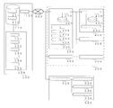
- FIG. 2 is a diagram showing a configuration in each device of an air conditioning system 1 having a failure diagnosis device that realizes a failure diagnosis of a diagnosis target possessed by the device to be inspected.
- the server 100 of the first embodiment is a failure diagnosis device for diagnosing whether or not a sensor or the like included in the air conditioner 200 has a failure. Therefore, the server 100 of the first embodiment includes a device information storage unit 110, a server-side data transmission / reception unit 120, and a data processing unit 130.
- the device information storage unit 110 has a storage device, and stores and stores data related to the air conditioner 200.
- the device information storage unit 110 records, stores, and stores data regarding each device of the outdoor unit 300 and the indoor unit 400 in the air conditioner 200 as device information 111.
- the device information 111 is data that can distinguish the same type of device such as a model name and a serial number with respect to the main body of the air conditioner 200.
- the device information storage unit 110 records, stores, and stores data related to the piping configuration as the piping configuration information 112 in association with the device information 111.
- the pipe configuration information 112 is data regarding the positions of pipes, sensors, actuators, and the like in the outdoor unit 300, the indoor unit 400, and the like in the air conditioner 200.
- the device information 111 and the piping configuration information 112 are used by the data processing unit 130 for processing to identify a diagnostic object included in the thermal image.
- the device information storage unit 110 does not have to store all the data from the beginning.
- the device information storage unit 110 may acquire and store data from another device such as the air conditioning device 200, another server, an air conditioning system, or the like.
- the device information storage unit 110 may store and store not only the data in the transmitted signal but also the data obtained by arithmetic processing in the server 100.
- the server-side data transmission / reception unit 120 serves as an interface for signal communication between the data processing unit 130, the air conditioning device 200, and the operation terminal device 500 via the telecommunication line 600.
- the communication of the server-side data transmission / reception unit 120 will be described as being performed between the air conditioner 200 and the operation terminal device 500, but the communication is performed with other devices and systems. You may.
- the data processing unit 130 performs a process of diagnosing whether or not the diagnostic object is out of order based on the data included in the signals sent from the air conditioner 200 and the operation terminal device 500.
- the data processing unit 130 of the first embodiment includes a data comparison unit 131, a failure diagnosis unit 132, a thermal image processing unit 133, a control data processing unit 134, and a result notification unit 135.
- the thermal image processing unit 133 processes the data related to the thermal image sent from the operation terminal device 500, identifies the diagnostic object contained in the thermal image, and acquires the measured temperature of the temperature sensor.
- the measured temperature is the actual temperature detected when the temperature sensor is normal.
- the thermal image processing unit 133 performs a process of acquiring the measured temperature from the thermal image
- the thermal image processing unit 133 performs a process using control data or the like provided from the air conditioner 200 described later to correct the measured temperature. May be good.
- the control data processing unit 134 requests the air conditioner 200 to provide control data regarding the diagnostic object specified by the thermal image processing unit 133. Then, as will be described later, the control data processing unit 134 performs a process of acquiring the control temperature from the control data in the signal sent from the air conditioner 200.
- the control data is data such as a control value used when controlling the device in the air conditioner 200 and a physical quantity value detected by various sensors used for calculating the control value.
- the control temperature is the temperature detected for the diagnostic object estimated from the control data from the air conditioner 200. When the object to be diagnosed is a temperature sensor, the temperature desired to be detected by the temperature sensor is the control temperature.
- the data comparison unit 131 calculates the temperature difference by comparing the measured temperature acquired by the thermal image processing unit 133 with the control temperature acquired by the control data processing unit 134.
- the failure diagnosis unit 132 performs a failure diagnosis of the object to be diagnosed based on the temperature difference calculated by the data comparison unit 131.
- the result notification unit 135 performs a process of notifying the diagnosis result by the failure diagnosis unit 132.
- the result notification unit 135 sends a signal including data related to the diagnosis result to the operation terminal device 500 via the server-side data transmission / reception unit 120.
- the failure diagnosis unit 132 may further include a diagnostic function that has been conventionally performed.
- the data processing unit 130 is composed of, for example, a device such as a control arithmetic processing device such as a CPU (Central Processing Unit), an analog circuit, a microcomputer having a digital circuit, and the like as hardware.
- the device information storage unit 110 is a non-volatile auxiliary capable of storing data for a long period of time, for example, a volatile storage device (not shown) such as a random access memory (RAM) capable of temporarily storing data, or a hard disk. It is composed of devices such as a storage device (not shown).
- the air conditioner 200 includes an outdoor unit 300 and an indoor unit 400.
- the outdoor unit 300 has an outdoor data transmission / reception unit 310, an outdoor device information holding unit 320, and an outdoor control data detection unit 330.
- the indoor unit 400 has an indoor side data transmission / reception unit 410, an indoor side device information holding unit 420, and an indoor side control data detection unit 430.
- the outdoor data transmission / reception unit 310 of the outdoor unit 300 transmits / receives signals including various data between the server 100, another outdoor unit 300, the indoor unit 400, and the operation terminal device 500.
- the outdoor data transmission / reception unit 310 is directly connected to the telecommunication line 600, but the present invention is not limited to this.
- the air conditioner 200 has a communication device for collecting communication of devices in the air conditioner 200 such as a plurality of outdoor units 300, and is connected to the telecommunication line 600 via the communication device to communicate with the server 100 and the server 100. Communication with the operation terminal device 500 may be performed.
- the outdoor device information holding unit 320 holds device-specific information possessed by each outdoor unit 300, such as a model, a model, and a serial number, as data. Since this data is the same as the device information 111 possessed by the server 100, it is referred to as the device information 111.
- the outdoor unit 300 in the air conditioner 200 transmits the device information 111 to the server 100 together with the control data. Thereby, for example, even when the air conditioner 200 has a plurality of devices such as the outdoor unit 300 and the indoor unit 400, the server 100 can uniquely identify the device associated with the control data.
- the outdoor control data detection unit 330 detects data used for sensor failure diagnosis, such as detection values of various sensors of the outdoor unit 300 and control values of actuators, as control data.
- FIG. 2 shows first temperature sensor control data 331, second temperature sensor control data 332, first electronic expansion valve control data 333, and second electronic expansion valve control data 334 as examples of control data. It is not limited to.
- the indoor data transmission / reception unit 410 of the indoor unit 400 transmits / receives signals including various data between the server 100, the outdoor unit 300, the other indoor unit 400, and the operation terminal device 500.
- the indoor data transmission / reception unit 410 will be described as being communication-connected to the outdoor unit 300 of the same refrigerant system, but the present invention is not limited to this.
- the indoor data transmission / reception unit 410 may be directly connected to the telecommunication line 600 and may directly communicate with the server 100 or the like.
- the air conditioner 200 has a communication device that collects the communication of the devices in the air conditioner 200, communicates with the telecommunication line 600 via the communication device, and connects with the server 100 and the operation terminal device 500. Communication may be performed.
- the indoor device information holding unit 420 holds device information 111 unique to each device 400, such as a model, a model, and a serial number, as data.
- the indoor unit 400 in the air conditioner 200 transmits the device information 111 to the server 100 together with the control data.
- the server 100 can uniquely identify the device associated with the control data.
- the indoor control data detection unit 430 detects data used for sensor failure diagnosis, such as detection values of various sensors of the indoor unit 400 and control values of actuators, as control data. Although not particularly shown in FIG. 2, the indoor control data detection unit 430 detects various control data by operating the indoor unit 400, similarly to the outdoor unit 300.
- the operation terminal device 500 includes a terminal-side data transmission / reception unit 510, a device information input unit 520, a thermal image imaging unit 530, and a data display unit 540.
- the terminal-side data transmission / reception unit 510 serves as an interface for signal communication with the server 100 and the air conditioner 200 via the telecommunication line 600.
- the thermal image imaging unit 530 has an infrared camera or the like, and generates thermal image data representing the temperature of the imaged portion captured by the user.
- thermal image data including a pipe or the like located around the diagnostic object is generated together with the diagnostic object.
- the device of the air conditioner 200 that allows the user to perform the failure diagnosis process on the server 100 is specified by the thermal image data and the data related to the device processed by the device information input unit 520.
- the thermal image imaging unit 530 is built in the operation terminal device 500, but the present invention is not limited to this.
- a device capable of capturing a thermal image may be connected to the operation terminal device 500 as an option.
- the thermal image captured by the thermal image imaging unit 530 may be a three-dimensional image or the like.
- the pipe included in the thermal image may be a pipe connecting the outdoor unit 300 and the indoor unit 400.
- the operation terminal device 500 may detect the temperature by a method other than infrared rays by the thermal image imaging unit 530.
- the device information input unit 520 has an input device or the like, and assists the user in inputting data related to the device to be diagnosed.
- the user inputs device-specific information such as a model name or a serial number as data via the device information input unit 520. Since this data is the same as the device information 111 possessed by the server 100, it is referred to as the device information 111.
- the device information input unit 520 has been described as being manually input by the user, but the present invention is not limited to this.
- the device information input unit 520 has a camera or the like as an image pickup device, and processes OCR (image character information acquisition) processing or QR code (registered trademark) of the captured image from the captured image such as characters to process the device information 111. May be obtained.
- the operation terminal device 500 may have the above-mentioned piping configuration information 112, specify a device or the like from the piping configuration represented by the thermal image of the thermal image data, and acquire the device information 111.
- the data display unit 540 has a display device, and displays a thermal image captured by the thermal image imaging unit 530, a failure diagnosis result included in a signal from the server 100, and the like.
- the diagnosis result can be transmitted to the user even if it is not displayed, the failure diagnosis result may not be displayed on the data display unit 540 regardless of the presence or absence of the data display unit 540.
- FIG. 3 is a diagram illustrating a flow of processing related to failure diagnosis performed by the server 100 according to the first embodiment.
- the data processing unit 130 of the server 100 mainly performs the processing related to the failure diagnosis.
- the first temperature sensor of the outdoor unit 300 is a diagnostic object for failure diagnosis.
- the thermal image processing unit 133 of the data processing unit 130 sends a signal including the device information 111 and the thermal image data from the operation terminal device 500
- the thermal image processing unit 133 is imaged based on the device information 111 stored in the device information storage unit 110.
- the device of the diagnostic object is specified (step ST1).
- the thermal image processing unit 133 uses the first temperature sensor, which is the diagnostic object in the thermal image, from the position of the pipe imaged together with the diagnostic object in the thermal image, based on the piping configuration information 112 of the specified device.
- Specify step ST2
- the thermal image processing unit 133 acquires the measured temperature of the first temperature sensor, which is the diagnostic object, based on the thermal image data (step ST3).
- the control data processing unit 134 requests the air conditioner 200 for control data corresponding to the diagnostic object specified by the thermal image processing unit 133 (step ST4).
- the outdoor unit 300 of the air conditioner 200 sends, upon request, a signal including the first temperature sensor control data 331 detected by the outdoor control data detection unit 330 together with the device information 111.
- the first temperature sensor control data 331 is the temperature detected by the first temperature sensor.
- the control data processing unit 134 obtains the device information 111 and the control data from the transmitted signal (step ST5), the control data processing unit 134 acquires the control temperature of the temperature sensor, which is the diagnostic object, based on the control data (step ST6).
- the data comparison unit 131 calculates the temperature difference between the measured temperature and the control temperature (step ST7). Then, the failure diagnosis unit 132 determines whether or not the temperature difference calculated by the data comparison unit 131 exceeds a predetermined reference range (step ST8). Then, when the failure diagnosis unit 132 determines that the temperature difference exceeds the reference range, it diagnoses that the first temperature sensor, which is the object to be diagnosed, has failed (step ST9).
- the large temperature difference indicates that the difference between the control temperature indicating the temperature detected by the first temperature sensor and the actually measured temperature indicating the temperature at the position where the first temperature sensor is actually exposed is large.
- the failure diagnosis unit 132 determines that the temperature difference does not exceed the reference range, it diagnoses that the first temperature sensor, which is the object to be diagnosed, has not failed (step ST10).
- the result notification unit 135 sends a signal including data related to the diagnosis result to the operation terminal device 500 via the server-side data transmission / reception unit 120 (step ST11).
- the thermal image processing unit 133 acquires the measured temperature of the temperature sensor to be diagnosed based on the thermal image data from the operation terminal device 500. do. Further, the control data processing unit 134 acquires the control temperature, which is the temperature detected by the temperature sensor used for controlling the air conditioner 200, based on the control data from the air conditioner 200 which is the device to be inspected.
- the failure diagnosis unit 132 performs a failure diagnosis of the object to be diagnosed from the temperature difference between the measured temperature calculated by the data comparison unit 131 and the control temperature. Therefore, the failure diagnosis can be easily and efficiently performed from the thermal image including the diagnostic object taken by the air conditioner 200. Then, the result notification unit 135 can quickly notify the diagnosis result.
- the device information storage unit 110 stores and stores the device information 111 and the piping configuration information 112 regarding the air conditioner 200 to be inspected, so that the thermal image processing unit 133 can make a diagnosis target from the thermal image data. Objects can be identified automatically and efficiently.
- FIG. 4 is a diagram illustrating a flow of processing related to failure diagnosis performed by the server 100 according to the second embodiment.
- the configuration of the equipment in the air conditioning system 1 in the second embodiment is the same as that in the first embodiment.
- the failure diagnosis device of the second embodiment performs failure diagnosis of equipment installed in the refrigerant circuit.
- the server 100 is a failure diagnosis device and the data processing unit 130 mainly performs the processing related to the failure diagnosis.
- FIG. 5 is a diagram illustrating the positional relationship of the first electronic expansion valve 350 in the refrigerant circuit of the air conditioner 200 according to the second embodiment.
- the first electronic expansion valve 350 included in the outdoor unit 300 which is the device of the air conditioner 200 to be inspected, will be described as a diagnostic object.
- the first electronic expansion valve 350 which is a drive device, is a valve used in the air conditioner 200 to allow the refrigerant to pass through the bypass pipe 351 when the refrigerant is supercooled. Therefore, the opening degree of the first electronic expansion valve 350 is adjusted when the air conditioner 200 supercools the refrigerant in the cooling operation, and the pressure of the refrigerant passing through the bypass pipe 351 is reduced. On the other hand, if the refrigerant is not supercooled, the first electronic expansion valve 350 is closed so that the refrigerant does not pass through the bypass pipe 351.
- the thermal image processing unit 133 takes an image based on the device information 111 of the device information storage unit 110.
- the device of the object is specified (step ST21).
- the thermal image processing unit 133 is a first electron expansion valve which is a diagnostic object in the thermal image from the position of the pipe imaged together with the diagnostic object in the thermal image based on the piping configuration information 112 of the specified device.
- Specify 350 (step ST22).
- the thermal image processing unit 133 acquires the measured temperature of the bypass pipe 351 before and after the first electron expansion valve 350, which is the diagnostic object, based on the thermal image data (step ST23).
- the position of the bypass pipe 351 before and after the first electronic expansion valve 350 is a predetermined position for acquiring the measured temperature of the first electronic expansion valve 350.
- the first electronic expansion valve 350 which is the diagnostic object of the second embodiment, depressurizes the refrigerant according to the opening degree.
- the temperature of the refrigerant is lowered by reducing the pressure. Therefore, in the bypass pipe 351, the temperature of the refrigerant changes before and after passing through the first electronic expansion valve 350 depending on the opening degree of the first electronic expansion valve 350. Therefore, the measured temperature of the first electronic expansion valve 350 is the difference in the pipe temperature of the bypass pipe 351 before and after the passage of the first electronic expansion valve 350 included in the thermal image together with the first electronic expansion valve 350.
- the thermal image processing unit 133 of the second embodiment is a thermal image including the equipment to be diagnosed and the pipes before and after the equipment even if the temperature sensor is not installed on at least one of the equipment to be diagnosed and the pipes before and after the equipment. It is possible to obtain a plurality of measured temperatures from the above and obtain the measured temperatures of the equipment to be diagnosed.
- the first electronic expansion valve 350 when the first electronic expansion valve 350 is operating normally and the opening degree is controlled, a difference occurs in the pipe temperature before and after the first electronic expansion valve 350 in the bypass pipe 351.
- the first electronic expansion valve 350 fails and the first electronic expansion valve 350 is closed, the refrigerant does not flow through the bypass pipe 351 and therefore there is a difference in the pipe temperature before and after the first electronic expansion valve 350. There is no such thing, and it becomes almost 0. Therefore, when the difference in the measured temperature between the pipes before and after the first electronic expansion valve 350 becomes zero, it can be diagnosed that the first electronic expansion valve 350 is out of order.
- the data comparison unit 131 calculates the difference in the measured temperature of the bypass pipe 351 before and after the first electronic expansion valve 350 as the measured temperature of the first electronic expansion valve 350. (Step ST24). Then, the failure diagnosis unit 132 determines whether or not the actually measured temperature of the first electronic expansion valve 350 is 0, which is a predetermined set value (step ST25). Then, when the failure diagnosis unit 132 determines that the measured temperature of the first electronic expansion valve 350 is 0, it diagnoses that the first electronic expansion valve 350, which is the object to be diagnosed, is out of order (step ST26).
- the failure diagnosis unit 132 determines that the measured temperature of the first electronic expansion valve 350 is not 0, it diagnoses that the first electronic expansion valve 350, which is the object to be diagnosed, has not failed (step ST27).
- the failure diagnosis unit 132 has been described as determining whether or not the measured temperature of the first electronic expansion valve 350 is 0, but the measured temperature of the first electronic expansion valve 350 is set to include 0. May be determined if is within the set range.
- the failure diagnosis unit 132 sends a signal including data related to the diagnosis result to the operation terminal device 500 via the server-side data transmission / reception unit 120 (step ST28).
- the thermal image processing unit 133 includes the front and rear pipes of the device to be diagnosed based on the thermal image data from the operation terminal device 500. Obtain the measured temperature.
- the failure diagnosis unit 132 performs a failure diagnosis of the object to be diagnosed from the measured temperature of the first electronic expansion valve 350 calculated by the data comparison unit 131. Therefore, the failure diagnosis can be easily and efficiently performed from the thermal image including the diagnostic object taken by the air conditioner 200. In particular, since the measured temperature at multiple positions can be obtained from the thermal image including the diagnostic object, even if the temperature sensors are not installed at all the positions where the temperature required for failure diagnosis can be obtained, the measured temperature at multiple positions can be obtained. Failure diagnosis can be performed using the measured temperature.
- FIG. 6 is a diagram illustrating a flow of processing related to failure diagnosis performed by the server 100 according to the third embodiment.
- the configuration of the equipment in the air conditioning system 1 in the third embodiment is the same as that in the first embodiment.
- the first electron expansion valve 350 shown in FIG. 5 will be described as being a diagnostic object.
- the server 100 is a failure diagnosis device and the data processing unit 130 mainly performs the processing related to the failure diagnosis.
- the failure diagnosis device of the third embodiment performs a failure diagnosis of the equipment installed in the refrigerant circuit as in the second embodiment.
- the thermal image processing unit 133 takes an image based on the device information 111 of the device information storage unit 110.
- the device of the object is specified (step ST31).
- the thermal image processing unit 133 is a first electron expansion valve which is a diagnostic object in the thermal image from the position of the pipe imaged together with the diagnostic object in the thermal image based on the piping configuration information 112 of the specified device.
- Specify 350 step ST32.
- the thermal image processing unit 133 acquires the measured temperature of the bypass pipe 351 before and after the first electron expansion valve 350, which is the diagnostic object, based on the thermal image data (step ST33).
- the control data processing unit 134 requests the air conditioner 200 for control data corresponding to the diagnostic object specified by the thermal image processing unit 133 (step ST34).
- the outdoor unit 300 of the air conditioner 200 sends, upon request, a signal including the first electronic expansion valve control data 333 detected by the outdoor control data detection unit 330 together with the device information 111.
- the first electronic expansion valve control data 333 pertaining to the first electronic expansion valve 350 is data relating to the opening degree.
- the control data processing unit 134 obtains the device information 111 and the control data from the transmitted signal (step ST35)
- the control data processing unit 134 controls the bypass pipes 351 before and after the first electronic expansion valve 350, which is the diagnostic object, based on the control data. Acquire the temperature (step ST36).
- the measured temperature of the first electronic expansion valve 350 is the difference in the pipe temperature of the bypass pipe 351 before and after the passage of the first electronic expansion valve 350 included in the thermal image together with the first electronic expansion valve 350, as in the second embodiment. do.
- the difference in piping temperature before and after the first electronic expansion valve 350 changes according to the opening degree of the first electronic expansion valve 350. Therefore, the difference in the pipe temperature before and after the first electronic expansion valve 350 can be obtained from the opening degree of the first electronic expansion valve 350, and this temperature controls the bypass pipe 351 before and after the first electronic expansion valve 350. It becomes the temperature. Therefore, if the temperature difference between the measured temperature and the control temperature is different, it can be diagnosed that the first electron expansion valve 350 is out of order.
- the data comparison unit 131 calculates the difference in the measured temperature of the bypass pipe 351 before and after the first electronic expansion valve 350 as the measured temperature of the first electronic expansion valve 350. Further, the data comparison unit 131 calculates the temperature difference between the measured temperature of the first electronic expansion valve 350 and the control temperature (step ST37). Then, the failure diagnosis unit 132 determines whether or not the temperature difference calculated by the data comparison unit 131 exceeds a predetermined reference range (step ST38). Then, when the failure diagnosis unit 132 determines that the temperature difference exceeds the reference range, it diagnoses that the first electron expansion valve 350, which is the object to be diagnosed, has failed (step ST39).
- the failure diagnosis unit 132 determines that the temperature difference does not exceed the reference range, it diagnoses that the first electron expansion valve 350, which is the object to be diagnosed, has not failed (step ST40).
- the reference range may be different depending on the opening degree of the first electronic expansion valve 350.
- the failure diagnosis unit 132 sends a signal including data related to the diagnosis result to the operation terminal device 500 via the server-side data transmission / reception unit 120 (step ST41).
- the thermal image processing unit 133 includes the front and rear pipes of the device to be diagnosed based on the thermal image data from the operation terminal device 500. Obtain the measured temperature. Further, the control data processing unit 134 determines the temperature of the equipment to be diagnosed and the pipes before and after the equipment to be diagnosed estimated from the control of the air conditioner 200 based on the control data from the air conditioner 200 to be inspected. Get a certain control temperature. The failure diagnosis unit 132 performs a failure diagnosis of the object to be diagnosed from the temperature difference between the measured temperature of the first electronic expansion valve 350 calculated by the data comparison unit 131 and the control temperature. Therefore, the failure diagnosis can be easily and efficiently performed from the thermal image including the diagnostic object taken by the air conditioner 200. In particular, since the measured temperature at a plurality of positions can be obtained from the thermal image including the object to be diagnosed, the failure diagnosis is performed using the measured temperature at a plurality of positions even if the temperature sensors are not installed at all the positions. be able to.
- the measured temperature of the first electronic expansion valve 350 and the control temperature are compared with the opening degree of the first electronic expansion valve 350 as the control temperature, but the present invention is not limited to this.
- the failure diagnosis device converts the measured temperature of the first electronic expansion valve 350 into the opening degree related to the measured temperature, and compares the opening degree related to the measured temperature of the first electronic expansion valve 350 with the opening degree related to the control. You may.
- the data comparison unit 131 calculates the temperature difference between the measured temperature and the control temperature, but the present invention is not limited to this.
- the data comparison unit 131 calculates the average temperature averaged over time for the measured temperature acquired by the thermal image processing unit 133 and the control temperature acquired by the control data processing unit 134, and obtains the temperature difference at the average temperature. It may be calculated. By using the time-averaged temperature, it is possible to suppress errors in the obtained measured temperature and the control temperature.
- the failure diagnosis device is the server 100 connected by the telecommunication line 600, but the present invention is not limited to this.
- the operation terminal device 500 may be a failure diagnosis device. Further, the operation terminal device 500 may have the function of the thermal image processing unit 133. Further, a device such as a centralized management device connected to the air conditioner 200 by a dedicated transmission line may be a failure diagnosis device.
- the server 100 which is the failure diagnosis device of the first to third embodiments, has acquired various data from the outdoor unit 300 and the indoor unit 400 of the air conditioner 200, but the present invention is not limited to this.
- the air conditioner 200 has a controller, a relay unit, and the like, data included in the signals sent from these devices may be acquired.
- the object to be diagnosed is a temperature sensor, but the object is not limited to the temperature sensor and can be applied to other sensors.
- the air conditioner 200 includes a compressor that compresses and discharges the refrigerant, and a heat exchanger that condenses and evaporates the refrigerant.
- the condensation temperature of the refrigerant passing through the heat exchanger can be obtained based on the pressure of the refrigerant discharged by the compressor. Therefore, if the failure diagnosis device can acquire the actually measured temperature representing the condensation temperature in the heat exchanger and the control temperature, the failure diagnosis device can perform failure diagnosis of the pressure sensor that detects the pressure of the refrigerant discharged by the compressor.
- the drive device to be diagnosed is an electronic expansion valve, but it can also be applied to other drive devices.
- the compressor can estimate the temperature of the compressor from a controlled rotation speed or the like. Therefore, if the measured temperature and the control temperature of the compressor can be obtained, the failure diagnosis of the compressor can be performed.
- the device to be inspected is the air conditioner 200 and the failure diagnosis is performed on the object to be diagnosed by the air conditioner 200. It is not limited.
- a refrigerating device or a hot water supply device can be applied as the device to be inspected. It can also be applied to other devices to be inspected in which a fluid passes through a pipe to which a diagnostic object is connected.
- 1 air conditioning system 100 server, 110 device information storage unit, 111 device information, 112 piping configuration information, 120 server side data transmission / reception unit, 130 data processing unit, 131 data comparison unit, 132 failure diagnosis unit, 133 thermal image processing unit , 134 control data processing unit, 135 result notification unit, 200 air conditioner, 300 outdoor unit, 310 outdoor data transmission / reception unit, 320 outdoor equipment information holding unit, 330 outdoor control data detection unit, 331 first temperature sensor control Data, 332, 2nd temperature sensor control data, 333, 1st electronic expansion valve control data, 334, 2nd electronic expansion valve control data, 350, 1st electronic expansion valve, 351 bypass piping, 400 indoor unit, 410 indoor data transmission / reception unit, 420 Indoor device information holding unit, 430 Indoor side control data detection unit, 500 Operation terminal device, 510 Terminal side data transmission / reception unit, 520 Equipment information input unit, 530 Thermal image imaging unit, 540 Data display unit, 600 Telecommunications line.
Abstract
開示に係る故障診断装置は、被点検装置が有する診断対象物の故障診断を行う故障診断装置であって、診断対象物を含む熱画像のデータを処理して実測温度を導く熱画像処理部と、被点検装置の制御に用いられる制御データに基づいて、被点検装置の制御から得られる温度を制御温度として導く制御データ処理部と、実測温度と制御温度との温度差を算出するデータ比較部と、データ比較部が算出した温度差に基づいて、診断対象物の故障診断を行う故障診断部とを備えるものである。
Description
この技術は、故障診断装置に関するものである。特に、点検に係る装置に用いられる機器などの故障診断に係るものである。
従来、空気調和装置などの装置の運転を点検する技術として、運転の変化を利用するものがある(たとえば、特許文献1参照)。この技術は、点検対象となる被点検装置において正常な運転が行われたときの運転情報と点検における運転情報との相違に基づいて、装置およびその構成機器の点検を行うものである。ここで、この技術の適用には、空気調和装置が有するセンサなどの機器が故障していないことが前提となる。
そこで、従来、人手により、診断対象物となるセンサに対して接触型温度センサを当て、目視により、温度を検出し、センサの故障診断が行われる。しかしながら、センサに対して接触型温度センサを当てて、温度を比較するのは、特に診断するセンサの数が多くなると非常に手間がかかる。
最近の空気調和装置などにおいては、冷媒の状態から温度を推測することがあり、空気調和装置が有するセンサの数は減少してきている。このため、従来技術として知られてきている故障診断技術が適用できなくなる可能性がある。また、被点検装置において、点検に必要な温度が検出可能な配管などに接触型センサを当て、作業者が温度を確認する作業が必要となる。このため、非常に効率が悪くなる。
さらに、従来技術は、制御に使われている冷凍サイクルの一部を利用して行うことが多いが、様々な故障診断を行うにあたり、冷凍サイクルに関わりのある多数の温度を利用することが必須となる。このような場合、習熟度の高い作業者は、必要なポイントを効率よく調査することができる。しかしながら、習熟度の低い作業者は、温度の計測を行うポイントが多くなることがあり、効率が悪くなる。
そこで、上記のような課題を解決し、故障診断を容易にして効率よく行うことができる故障診断装置を提供することを目的とする。
この開示に係る故障診断装置は、被点検装置が有する診断対象物の故障診断を行う故障診断装置であって、診断対象物を含む熱画像のデータを処理して実測温度を導く熱画像処理部と、被点検装置の制御に用いられる制御データに基づいて、被点検装置の制御から得られる温度を制御温度として導く制御データ処理部と、実測温度と制御温度との温度差を算出するデータ比較部と、データ比較部が算出した温度差に基づいて、診断対象物の故障診断を行う故障診断部とを備えるものである。
この開示によれば、故障診断部が、診断対象物を含む熱画像のデータから得られる実測温度と診断対象物を有する被点検装置の制御に用いられる制御データから得られる制御温度との温度差に基づき、診断対象物の故障診断を容易に効率よく行うことができる。
以下、実施の形態に係る故障診断装置について、図面などを参照しながら説明する。以下の図面において、同一の符号を付したものは、同一またはこれに相当するものであり、以下に記載する実施の形態の全文において共通することとする。また、図面では各構成部材の大きさの関係が実際のものとは異なる場合がある。そして、明細書全文に表わされている構成要素の形態は、あくまでも例示であって、明細書に記載された形態に限定するものではない。特に構成要素の組み合わせは、各実施の形態における組み合わせのみに限定するものではなく、他の実施の形態に記載した構成要素を別の実施の形態に適用することができる。また、添字で区別などしている複数の同種の装置または機器などについて、特に区別したり、特定したりする必要がない場合には、添字などを省略して記載する場合がある。
実施の形態1.
[空気調和システム1の構成]
図1は、実施の形態1に係る故障診断装置を有する空気調和システム1の構成例を示す図である。図1に示すように、実施の形態1の空気調和システム1は、サーバ100、空気調和装置200および操作端末装置500を電気通信回線600で通信可能に接続して構成される。ここで、電気通信回線600は、一般的な公衆電気回線だけでなく、LAN(Local Area Network)などでもよい。また、電気通信回線600は、有線接続だけでなく、無線接続でもよい。
[空気調和システム1の構成]
図1は、実施の形態1に係る故障診断装置を有する空気調和システム1の構成例を示す図である。図1に示すように、実施の形態1の空気調和システム1は、サーバ100、空気調和装置200および操作端末装置500を電気通信回線600で通信可能に接続して構成される。ここで、電気通信回線600は、一般的な公衆電気回線だけでなく、LAN(Local Area Network)などでもよい。また、電気通信回線600は、有線接続だけでなく、無線接続でもよい。
実施の形態1では、サーバ100が故障診断装置であるものとして説明する。サーバ100は、空気調和装置200および操作端末装置500から電気通信回線600を介して送られる信号に含まれる各種データを処理し、被点検装置である空気調和装置200が有する、物理量を検出するセンサなどの診断対象物の故障診断を行う。実施の形態1では、物理量として温度を検出する温度センサを診断対象物とする故障診断について説明する。特に限定するものではないが、サーバ100は、空気調和装置200および操作端末装置500以外の装置から、外気の温度、湿度または天候などのデータを取得し、これらのデータを含めて故障診断に係る処理を行ってもよい。
被点検装置となる実施の形態1の空気調和装置200は、室外機300および室内機400を有する。空気調和装置200は、室外機300および室内機400内の機器を配管で接続して冷媒回路を構成し、冷媒回路内に冷媒を循環させて対象空間の空気調和を行う装置である。ただし、空気調和装置200は、この構成に限定するものではない。たとえば、空気調和装置200は、室外機300および400以外に、コントローラ、中継ユニットなどを有する構成でもよい。また、空気調和装置200は、接続した配管内において、水、ブラインなど、冷媒以外の流体となる熱媒体を循環などさせてもよい。
操作端末装置500は、利用者が操作する端末装置である。実施の形態1の操作端末装置500は、利用者が入力および撮像などを処理して得られたデータを含む信号をサーバ100に送る。また、操作端末装置500は、サーバ100から送られる故障診断結果のデータを含む信号を受信し、利用者に診断結果を通知する。ここで、操作端末装置500は、パーソナルコンピュータ、スマートフォンなどの装置とするが、これに限定されるものではない。たとえば、操作端末装置500は、熱画像を撮像することができるサーモカメラなどの入力端末装置としてもよい。
図2は、被点検装置が有する診断対象物の故障診断を実現する故障診断装置を有する空気調和システム1の各装置における構成を示す図である。
[サーバ100の構成]
前述したように、実施の形態1のサーバ100は、空気調和装置200が有するセンサなどが故障しているかどうかを診断する故障診断装置となる。このため、実施の形態1のサーバ100は、機器情報保存部110、サーバ側データ送受信部120およびデータ処理部130を備える。
前述したように、実施の形態1のサーバ100は、空気調和装置200が有するセンサなどが故障しているかどうかを診断する故障診断装置となる。このため、実施の形態1のサーバ100は、機器情報保存部110、サーバ側データ送受信部120およびデータ処理部130を備える。
機器情報保存部110は、記憶装置を有し、空気調和装置200に関するデータを記憶し、保存する。特に、機器情報保存部110は、空気調和装置200における室外機300および室内機400が有す各機器に関するデータを、機器情報111として記録および記憶し、保存する。機器情報111は、空気調和装置200の本体に関し、たとえば、型名、製造番号などの同種の機器を区別することができるデータである。また、機器情報保存部110は、配管の構成に関するデータを配管構成情報112として、機器情報111と対応付けて記録および記憶し、保存する。配管構成情報112は、空気調和装置200内の室外機300および室内機400などにおける配管、センサおよびアクチュエータなどの位置に関するデータである。ここでは、機器情報111および配管構成情報112は、データ処理部130が熱画像に含まれる診断対象物特定する処理に用いられる。ここで、機器情報保存部110は、すべてのデータを最初から保存しておかなくてもよい。たとえば、機器情報保存部110は、空気調和装置200など他の装置、他のサーバ、空気調和システムなどからデータを取得し、保存してもよい。また、機器情報保存部110は、送られた信号中のデータだけでなく、サーバ100において演算処理などして得られたデータを記憶し、保存してもよい。
サーバ側データ送受信部120は、電気通信回線600を介して、データ処理部130と空気調和装置200および操作端末装置500との信号通信を行うインターフェースとなる。ここで、特に断らない限り、サーバ側データ送受信部120の通信は、空気調和装置200および操作端末装置500との間で行うものとして説明するが、他の装置およびシステムとの間で通信を行ってもよい。
データ処理部130は、空気調和装置200および操作端末装置500から送られる信号に含まれるデータに基づいて、診断対象物が故障しているかどうかを診断する処理を行う。実施の形態1のデータ処理部130は、データ比較部131、故障診断部132、熱画像処理部133、制御データ処理部134および結果通知部135を有する。
熱画像処理部133は、操作端末装置500から送られる熱画像に係るデータを処理し、熱画像内に含まれる診断対象物を特定し、温度センサの実測温度を取得する処理を行う。診断対象物が温度センサである場合、実測温度は、温度センサが正常である場合に検出される実温度となる。ここで、熱画像処理部133は、熱画像から実測温度を取得する処理を行う際、後述する空気調和装置200から提供される制御データなどを利用した処理を行って、実測温度を補正してもよい。
制御データ処理部134は、熱画像処理部133が特定した診断対象物に関する制御データの提供を、空気調和装置200に対して要求する。そして、制御データ処理部134は、後述するように、空気調和装置200から送られる信号中の制御データから制御温度を取得する処理を行う。制御データは、空気調和装置200内の機器を制御する際に用いられた制御値および制御値の算出などに用いられる各種センサが検出した物理量の値などのデータである。制御温度は、空気調和装置200からの制御データから推定される診断対象物に関して検出された温度となる。診断対象物が温度センサの場合は、温度センサが検出したい温度が制御温度となる。
データ比較部131は、熱画像処理部133が取得した実測温度と制御データ処理部134が取得した制御温度とを比較して温度差を算出する。故障診断部132は、データ比較部131が算出した温度差に基づいて、診断対象物の故障診断を行う。結果通知部135は、故障診断部132は、診断した結果を通知する処理を行う。実施の形態1では、結果通知部135は、診断結果に係るデータを含む信号を、サーバ側データ送受信部120を介して、操作端末装置500に送る。ここで、故障診断部132は、従来行われていた診断機能をさらに含むものであってもよい。
ここで、データ処理部130は、ハードウェアとしては、たとえば、CPU(Central Processing Unit)などの制御演算処理装置、アナログ回路、デジタル回路などを有するマイクロコンピュータなどの装置で構成されている。また、機器情報保存部110は、たとえば、データを一時的に記憶できるランダムアクセスメモリ(RAM)などの揮発性記憶装置(図示せず)、ハードディスクなど、データを長期的に記憶できる不揮発性の補助記憶装置(図示せず)などの装置で構成されている。
[空気調和装置200の構成]
図1および図2に示すように、空気調和装置200は、室外機300と室内機400とを備える。室外機300は、室外側データ送受信部310、室外側機器情報保持部320および室外側制御データ検出部330を有する。また、室内機400は、室内側データ送受信部410、室内側機器情報保持部420および室内側制御データ検出部430を有する。
図1および図2に示すように、空気調和装置200は、室外機300と室内機400とを備える。室外機300は、室外側データ送受信部310、室外側機器情報保持部320および室外側制御データ検出部330を有する。また、室内機400は、室内側データ送受信部410、室内側機器情報保持部420および室内側制御データ検出部430を有する。
室外機300の室外側データ送受信部310は、サーバ100、他の室外機300、室内機400および操作端末装置500との間で、各種データを含む信号を送受信する。ここで、図2では、室外側データ送受信部310は、電気通信回線600と直接的に接続されているが、これに限定するものではない。たとえば、空気調和装置200が、複数の室外機300など、空気調和装置200内の機器の通信をまとめる通信装置を有し、通信装置を介して、電気通信回線600と通信接続し、サーバ100および操作端末装置500との通信を行うようにしてもよい。
室外側機器情報保持部320は、形式、機種、製造番号など、各室外機300が有する機器固有の情報をデータとして保持する。このデータは、サーバ100が有する機器情報111と同様のデータであるため、機器情報111とする。空気調和装置200内の室外機300は、制御データとともに、機器情報111をサーバ100に送信する。これにより、たとえば、空気調和装置200が、室外機300および室内機400などの機器を複数有する場合でも、サーバ100は、制御データと関連づけられた機器を一意に特定することができる。
室外側制御データ検出部330は、室外機300が有する各種センサの検出値およびアクチュエータの制御値など、センサ故障診断に用いるデータを制御データとして検出する。図2は、制御データの例として、第1温度センサ制御データ331、第2温度センサ制御データ332、第1電子膨張弁制御データ333および第2電子膨張弁制御データ334を示しているが、これに限定するものではない。
室内機400の室内側データ送受信部410は、サーバ100、室外機300、他の室内機400および操作端末装置500との間で、各種データを含む信号を送受信する。ここで、室内側データ送受信部410は、同じ冷媒系統の室外機300と通信接続されているものとして説明するが、これに限定するものではない。たとえば、室内側データ送受信部410は、電気通信回線600と直接的に接続され、サーバ100などと直接的に通信を行ってもよい。また、たとえば、空気調和装置200が空気調和装置200内の機器の通信をまとめる通信装置を有し、通信装置を介して、電気通信回線600と通信接続し、サーバ100および操作端末装置500との通信を行うようにしてもよい。
室内側機器情報保持部420は、形式、機種、製造番号など、各室内機400が有する機器固有の機器情報111をデータとして保持する。空気調和装置200内の室内機400は、機器情報111を、制御データとともにサーバ100に送信する。これにより、サーバ100は、制御データと関連づけられた機器を一意に特定することができる。
室内側制御データ検出部430は、室内機400が有する各種センサの検出値およびアクチュエータの制御値など、センサ故障診断に用いるデータを制御データとして検出する。図2では、特に図示していないが、室外機300と同様に、室内側制御データ検出部430は、室内機400の運転により、各種制御データを検出する。
[操作端末装置500の構成]
図2に示すように、操作端末装置500は、端末側データ送受信部510、機器情報入力部520、熱画像撮像部530およびデータ表示部540を備える。端末側データ送受信部510は、電気通信回線600を介して、サーバ100および空気調和装置200と信号通信を行うインターフェースとなる。
図2に示すように、操作端末装置500は、端末側データ送受信部510、機器情報入力部520、熱画像撮像部530およびデータ表示部540を備える。端末側データ送受信部510は、電気通信回線600を介して、サーバ100および空気調和装置200と信号通信を行うインターフェースとなる。
熱画像撮像部530は、赤外線カメラなどを有し、利用者が撮像した撮影した部分の温度を表す熱画像のデータを生成する。実施の形態1では、診断対象物とともに、診断対象物の周辺に位置する配管などを含む熱画像のデータが生成される。熱画像データと機器情報入力部520が処理した機器に関するデータとにより、利用者がサーバ100に故障診断処理を行わせる空気調和装置200の機器を特定する。ここで、図2では、熱画像撮像部530が操作端末装置500に内蔵されているが、これに限定するものではない。たとえば、オプションとして熱画像を撮像可能な装置が、操作端末装置500に接続されていてもよい。ここで、熱画像撮像部530が撮影する熱画像は、3次元画像などでもよい。また、熱画像に含まれる配管は、室外機300と室内機400とを接続する配管などでもよい。また、操作端末装置500は、熱画像撮像部530による赤外線以外の方法で温度を検出してもよい。
機器情報入力部520は、入力装置などを有し、利用者が診断対象物となる機器に関するデータを入力する支援を行う。利用者は、機器情報入力部520を介して、形名または製造番号などの機器固有の情報をデータとして入力する。このデータは、サーバ100が有する機器情報111と同様のデータであるため、機器情報111とする。ここで、機器情報入力部520は、利用者が手入力するものとして説明したが、これに限定するものではない。たとえば、機器情報入力部520は、撮像装置であるカメラなどを有し、文字などの撮像画像からOCR(画像文字情報取得)処理または撮像画像のQRコード(登録商標)を処理して機器情報111を取得してもよい。また、操作端末装置500が、前述した配管構成情報112を有し、熱画像データの熱画像が表す配管構成から機器などを特定し、機器情報111を取得してもよい。
データ表示部540は、表示装置を有し、熱画像撮像部530が撮像した熱画像、サーバ100からの信号に含まれる故障診断結果などを表示する。ここで、表示でなくても利用者に診断結果を伝えることができる場合には、データ表示部540の有無に関わらず、データ表示部540に故障診断結果を表示させなくてもよい。
図3は、実施の形態1に係るサーバ100が行う故障診断に係る処理の流れを説明する図である。ここで、実施の形態1では、サーバ100のデータ処理部130が、主として故障診断に係る処理を行うものとして説明する。ここでは、室外機300が有する第1温度センサが故障診断を行う診断対象物であるものとして説明する。
データ処理部130の熱画像処理部133は、操作端末装置500から機器情報111および熱画像データを含む信号が送られると、機器情報保存部110に保存された機器情報111に基づいて、撮像された診断対象物の機器を特定する(ステップST1)。そして、熱画像処理部133は、特定した機器の配管構成情報112に基づいて、熱画像内における診断対象物とともに撮像された配管の位置などから熱画像における診断対象物である第1温度センサを特定する(ステップST2)。そして、熱画像処理部133は、熱画像のデータに基づいて、診断対象物である第1温度センサの実測温度を取得する(ステップST3)。
制御データ処理部134は、空気調和装置200に熱画像処理部133が特定した診断対象物に対応する制御データを要求する(ステップST4)。空気調和装置200の室外機300では、要求に応じて、室外側制御データ検出部330が検出した第1温度センサ制御データ331を含む信号を、機器情報111とともに送る。ここでは、第1温度センサ制御データ331は、第1温度センサが検出した温度となる。制御データ処理部134は、送られた信号から機器情報111および制御データを得ると(ステップST5)、制御データに基づいて、診断対象物である温度センサの制御温度を取得する(ステップST6)。
データ比較部131は、実測温度と制御温度との温度差を算出する(ステップST7)。そして、故障診断部132は、データ比較部131が算出した温度差が、あらかじめ定められた基準範囲を超えているかどうかを判定する(ステップST8)。そして、故障診断部132は、温度差が基準範囲を超えていると判定すると、診断対象物である第1温度センサが故障していると診断する(ステップST9)。温度差が大きいことは、第1温度センサが検出したとする温度を表す制御温度と第1温度センサが実際に晒されている位置における温度を表す実測温度との差が大きいことを示す。一方、故障診断部132は、温度差が基準範囲を超えていないと判定すると、診断対象物である第1温度センサが故障していないと診断する(ステップST10)。
結果通知部135は、診断結果に係るデータを含む信号を、サーバ側データ送受信部120を介して、操作端末装置500に送る(ステップST11)。
以上のように、実施の形態1の故障診断装置によれば、操作端末装置500からの熱画像のデータに基づいて、熱画像処理部133が、診断対象物となる温度センサの実測温度を取得する。また、制御データ処理部134が、被点検装置となる空気調和装置200からの制御データに基づき、空気調和装置200の制御に用いられた温度センサの検出した温度である制御温度を取得する。データ比較部131が算出した実測温度と制御温度との温度差から故障診断部132が診断対象物の故障診断を行う。したがって、空気調和装置200において撮影された診断対象物を含む熱画像から、容易に効率よく故障診断を行うことができる。そして、結果通知部135により、診断結果をすばやく通知することができる。
また、機器情報保存部110が、被点検装置となる空気調和装置200に関する機器情報111および配管構成情報112を記憶し、保存することで、熱画像処理部133が、熱画像のデータから診断対象物を自動的に効率よく特定することができる。
実施の形態2.
図4は、実施の形態2に係るサーバ100が行う故障診断に係る処理の流れを説明する図である。実施の形態2における空気調和システム1における機器の構成は、実施の形態1と同様である。実施の形態2の故障診断装置は、冷媒回路に設置された機器の故障診断を行うものである。実施の形態2においてもサーバ100が故障診断装置であり、データ処理部130が、主として故障診断に係る処理を行うものとして説明する。
図4は、実施の形態2に係るサーバ100が行う故障診断に係る処理の流れを説明する図である。実施の形態2における空気調和システム1における機器の構成は、実施の形態1と同様である。実施の形態2の故障診断装置は、冷媒回路に設置された機器の故障診断を行うものである。実施の形態2においてもサーバ100が故障診断装置であり、データ処理部130が、主として故障診断に係る処理を行うものとして説明する。
図5は、実施の形態2に係る空気調和装置200における第1電子膨張弁350の冷媒回路における位置関係を説明する図である。ここでは、被点検装置となる空気調和装置200の機器である室外機300が有する第1電子膨張弁350が診断対象物であるものとして説明する。駆動機器である第1電子膨張弁350は、空気調和装置200において、冷媒を過冷却する際にバイパス配管351に冷媒を通過させるために用いられる弁である。したがって、第1電子膨張弁350は、空気調和装置200が冷房運転において冷媒を過冷却する際には開度が調整され、バイパス配管351を通過する冷媒を減圧する。一方、第1電子膨張弁350は、冷媒を過冷却しない場合には、バイパス配管351に冷媒を通過させないように閉止される。
図4に示すように、熱画像処理部133は、操作端末装置500から機器情報111および熱画像データを含む信号が送られると、機器情報保存部110の機器情報111に基づき、撮像された診断対象物の機器を特定する(ステップST21)。そして、熱画像処理部133は、特定した機器の配管構成情報112に基づいて、熱画像内における診断対象物とともに撮像された配管の位置などから熱画像における診断対象物である第1電子膨張弁350を特定する(ステップST22)。そして、熱画像処理部133は、熱画像のデータに基づいて、診断対象物である第1電子膨張弁350の前後におけるバイパス配管351に関する実測温度を取得する(ステップST23)。第1電子膨張弁350の前後におけるバイパス配管351の位置は、第1電子膨張弁350の実測温度を取得するために、あらかじめ定められた位置である。
ここで、実施の形態2における診断対象物となる機器の実測温度について説明する。実施の形態2の診断対象物である第1電子膨張弁350は、開度に応じて冷媒を減圧する。冷媒は、減圧することで温度が下がる。このため、バイパス配管351において、第1電子膨張弁350の開度によって、第1電子膨張弁350の通過前後で冷媒の温度が変化する。そこで、第1電子膨張弁350の実測温度は、第1電子膨張弁350とともに熱画像に含まれる第1電子膨張弁350の通過前後のバイパス配管351の配管温度の差とする。このように、実施の形態2の熱画像処理部133は、診断対象物となる機器および機器前後の配管の少なくとも一方に温度センサが設置されていなくても、機器の前後の配管を含む熱画像から複数の実測温度を得て、診断対象物となる機器の実測温度を取得することができる。
たとえば、第1電子膨張弁350が正常に動作しており、開度が制御されている場合には、バイパス配管351において、第1電子膨張弁350の前後の配管温度に差が発生する。一方、第1電子膨張弁350が故障し、第1電子膨張弁350が閉止しているときは、バイパス配管351に冷媒が流れないため、第1電子膨張弁350の前後の配管温度に差がなく、ほぼ0となる。したがって、第1電子膨張弁350の前後の配管における実測温度の差が0になると、第1電子膨張弁350が故障していると診断することができる。
データ比較部131は、第1電子膨張弁350の前後におけるバイパス配管351に関する実測温度の差を、第1電子膨張弁350の実測温度として算出する。(ステップST24)。そして、故障診断部132は、第1電子膨張弁350の実測温度が、あらかじめ定められた設定値である0であるかどうかを判定する(ステップST25)。そして、故障診断部132は、第1電子膨張弁350の実測温度が0であると判定すると、診断対象物である第1電子膨張弁350が故障していると診断する(ステップST26)。一方、故障診断部132は、第1電子膨張弁350の実測温度が0でないと判定すると、診断対象物である第1電子膨張弁350が故障していないと診断する(ステップST27)。ここでは、故障診断部132が、第1電子膨張弁350の実測温度が0であるかどうかを判定するものとして説明したが、0を含む範囲を設定して第1電子膨張弁350の実測温度が設定範囲内にあるかどうかを判定してもよい。
故障診断部132は、診断結果に係るデータを含む信号を、サーバ側データ送受信部120を介して、操作端末装置500に送る(ステップST28)。
以上のように、実施の形態2の故障診断装置によれば、操作端末装置500からの熱画像のデータに基づいて、熱画像処理部133が、診断対象物となる機器の前後の配管を含む実測温度を取得する。データ比較部131が算出した第1電子膨張弁350の実測温度から故障診断部132が診断対象物の故障診断を行う。したがって、空気調和装置200において撮影された診断対象物を含む熱画像から容易に効率よく故障診断を行うことができる。特に、診断対象物を含む熱画像から複数の位置における実測温度を得ることができるため、故障診断に必要な温度を得られる位置のすべてに温度センサが設置されていなくても、複数の位置の実測温度を用いて故障診断を行うことができる。
実施の形態3.
図6は、実施の形態3に係るサーバ100が行う故障診断に係る処理の流れを説明する図である。実施の形態3における空気調和システム1における機器の構成は、実施の形態1と同様である。そして、図5に示す第1電子膨張弁350が診断対象物であるものとして説明する。実施の形態3においてもサーバ100が故障診断装置であり、データ処理部130が、主として故障診断に係る処理を行うものとして説明する。実施の形態3の故障診断装置は、実施の形態2と同様に、冷媒回路に設置された機器の故障診断を行うものである。
図6は、実施の形態3に係るサーバ100が行う故障診断に係る処理の流れを説明する図である。実施の形態3における空気調和システム1における機器の構成は、実施の形態1と同様である。そして、図5に示す第1電子膨張弁350が診断対象物であるものとして説明する。実施の形態3においてもサーバ100が故障診断装置であり、データ処理部130が、主として故障診断に係る処理を行うものとして説明する。実施の形態3の故障診断装置は、実施の形態2と同様に、冷媒回路に設置された機器の故障診断を行うものである。
図6に示すように、熱画像処理部133は、操作端末装置500から機器情報111および熱画像データを含む信号が送られると、機器情報保存部110の機器情報111に基づき、撮像された診断対象物の機器を特定する(ステップST31)。そして、熱画像処理部133は、特定した機器の配管構成情報112に基づいて、熱画像内における診断対象物とともに撮像された配管の位置などから熱画像における診断対象物である第1電子膨張弁350を特定する(ステップST32)。そして、熱画像処理部133は、熱画像のデータに基づいて、診断対象物である第1電子膨張弁350の前後におけるバイパス配管351に関する実測温度を取得する(ステップST33)。
制御データ処理部134は、空気調和装置200に熱画像処理部133が特定した診断対象物に対応する制御データを要求する(ステップST34)。空気調和装置200の室外機300では、要求に応じて、室外側制御データ検出部330が検出した第1電子膨張弁制御データ333を含む信号を、機器情報111とともに送る。ここでは、第1電子膨張弁350に係る第1電子膨張弁制御データ333は、開度に関するデータとなる。制御データ処理部134は、送られた信号から機器情報111および制御データを得ると(ステップST35)、制御データに基づき、診断対象物である第1電子膨張弁350の前後におけるバイパス配管351に関する制御温度を取得する(ステップST36)。
ここで、実施の形態3における診断対象物となる機器の実測温度と制御温度とについて説明する。第1電子膨張弁350の実測温度は、実施の形態2と同様に、第1電子膨張弁350とともに熱画像に含まれる第1電子膨張弁350の通過前後のバイパス配管351の配管温度の差とする。ここで、第1電子膨張弁350の前後の配管温度の差は、第1電子膨張弁350の開度に応じて変化する。このため、第1電子膨張弁350の開度から第1電子膨張弁350の前後の配管温度の差を得ることができ、この温度が、第1電子膨張弁350の前後におけるバイパス配管351に関する制御温度となる。したがって、実測温度と制御温度との温度差が異なると、第1電子膨張弁350が故障していると診断することができる。
データ比較部131は、第1電子膨張弁350の前後におけるバイパス配管351に関する実測温度の差を、第1電子膨張弁350の実測温度として算出する。また、データ比較部131は、第1電子膨張弁350の実測温度と制御温度との温度差を算出する(ステップST37)。そして、故障診断部132は、データ比較部131が算出した温度差が、あらかじめ定められた基準範囲を超えているかどうかを判定する(ステップST38)。そして、故障診断部132は、温度差が基準範囲を超えていると判定すると、診断対象物である第1電子膨張弁350が故障していると診断する(ステップST39)。一方、故障診断部132は、温度差が基準範囲を超えていないと判定すると、診断対象物である第1電子膨張弁350が故障していないと診断する(ステップST40)。ここで、実施の形態3においては、第1電子膨張弁350の開度によって、基準範囲が異なるようにしてもよい。
故障診断部132は、診断結果に係るデータを含む信号を、サーバ側データ送受信部120を介して、操作端末装置500に送る(ステップST41)。
以上のように、実施の形態3の故障診断装置によれば、操作端末装置500からの熱画像のデータに基づいて、熱画像処理部133が、診断対象物となる機器の前後の配管を含む実測温度を取得する。また、制御データ処理部134が、被点検装置となる空気調和装置200からの制御データに基づき、空気調和装置200の制御から推定される診断対象物となる機器および機器の前後の配管の温度である制御温度を取得する。データ比較部131が算出した第1電子膨張弁350の実測温度と制御温度との温度差から故障診断部132が診断対象物の故障診断を行う。したがって、空気調和装置200において撮影された診断対象物を含む熱画像から、容易に効率よく故障診断を行うことができる。特に、診断対象物を含む熱画像から複数の位置における実測温度を得ることができるため、すべての位置に温度センサが設置されていなくても、複数の位置の実測温度を用いて故障診断を行うことができる。
ここで、実施の形態3の故障診断装置では、第1電子膨張弁350の開度を制御温度として、第1電子膨張弁350の実測温度と制御温度とを比較したが、これに限定しない。故障診断装置は、第1電子膨張弁350の実測温度を、実測温度に係る開度に変換して、第1電子膨張弁350の実測温度に係る開度と制御に係る開度とを比較してもよい。
実施の形態4.
上述した実施の形態1~実施の形態3では、データ比較部131は、実測温度と制御温度との温度差を算出したが、これに限定するものではない。たとえば、データ比較部131は、熱画像処理部133が取得した実測温度および制御データ処理部134が取得した制御温度について、それぞれ時間平均した平均の温度を算出して、平均の温度における温度差を算出してもよい。時間平均した温度とすることで、得られる実測温度および制御温度の誤差を抑えることができる。
上述した実施の形態1~実施の形態3では、データ比較部131は、実測温度と制御温度との温度差を算出したが、これに限定するものではない。たとえば、データ比較部131は、熱画像処理部133が取得した実測温度および制御データ処理部134が取得した制御温度について、それぞれ時間平均した平均の温度を算出して、平均の温度における温度差を算出してもよい。時間平均した温度とすることで、得られる実測温度および制御温度の誤差を抑えることができる。
実施の形態1~実施の形態3の故障診断装置は、電気通信回線600で接続されたサーバ100であったが、これに限定するものではない。操作端末装置500が故障診断装置であってもよい。また、熱画像処理部133の機能を操作端末装置500が有していてもよい。さらに、空気調和装置200と専用の伝送線で接続された集中管理装置などの装置が故障診断装置であってもよい。
また、実施の形態1~実施の形態3の故障診断装置であるサーバ100は、空気調和装置200の室外機300および室内機400から各種データを取得したが、これに限定するものではない。空気調和装置200がコントローラ、中継ユニットなどを有する場合は、これらの装置から送られる信号に含まれるデータを取得してもよい。
上述した実施の形態1の故障診断装置では、診断対象物を温度センサとしたが、温度センサに限定するものではなく、他のセンサにも適用することができる。たとえば、空気調和装置200は、冷媒を圧縮して吐出する圧縮機並びに冷媒の凝縮および蒸発を行う熱交換器を有する。冷媒回路においては、圧縮機が吐出する冷媒の圧力に基づいて、熱交換器を通過する冷媒の凝縮温度を求めることができる。そこで、故障診断装置は、熱交換器における凝縮温度を表す実測温度と制御温度とを取得することができれば、圧縮機が吐出する冷媒の圧力を検出する圧力センサの故障診断を行うことができる。
また、上述した実施の形態2および実施の形態3の故障診断装置では、診断対象物となる駆動機器を電子膨張弁としたが、他の駆動機器にも適用することができる。たとえば、空気調和装置200において、圧縮機は、制御される回転数などにより圧縮機の温度が推定可能である。そこで、圧縮機の実測温度と制御温度とを取得することができれば、圧縮機の故障診断を行うことができる。
前述した実施の形態1および実施の形態2の故障診断装置は、被点検装置を空気調和装置200とし、空気調和装置200の診断対象物に対して故障診断を行うことについて説明したが、これに限定するものではない。たとえば、冷凍装置または給湯装置などを被点検装置として適用することができる。また、診断対象物が接続された配管を流体が通過する他の被点検装置にも適用することができる。
1 空気調和システム、100 サーバ、110 機器情報保存部、111 機器情報、112 配管構成情報、120 サーバ側データ送受信部、130 データ処理部、131 データ比較部、132 故障診断部、133 熱画像処理部、134 制御データ処理部、135 結果通知部、200 空気調和装置、300 室外機、310 室外側データ送受信部、320 室外側機器情報保持部、330 室外側制御データ検出部、331 第1温度センサ制御データ、332 第2温度センサ制御データ、333 第1電子膨張弁制御データ、334 第2電子膨張弁制御データ、350 第1電子膨張弁、351 バイパス配管、400 室内機、410 室内側データ送受信部、420 室内側機器情報保持部、430 室内側制御データ検出部、500 操作端末装置、510 端末側データ送受信部、520 機器情報入力部、530 熱画像撮像部、540 データ表示部、600 電気通信回線。
Claims (9)
- 被点検装置が有する診断対象物の故障診断を行う故障診断装置であって、
前記診断対象物を含む熱画像のデータを処理して実測温度を導く熱画像処理部と、
前記被点検装置の制御に用いられる制御データに基づいて、前記被点検装置の制御から得られる温度を制御温度として導く制御データ処理部と、
前記実測温度と前記制御温度との温度差を算出するデータ比較部と、
前記データ比較部が算出した前記温度差に基づいて、前記診断対象物の故障診断を行う故障診断部と
を備える故障診断装置。 - 前記診断対象物はセンサであり、前記制御温度は、前記被点検装置の制御に用いられる前記センサが検出した物理量の値から導き出される温度である請求項1に記載の故障診断装置。
- 前記診断対象物は駆動機器であり、前記制御温度は、前記駆動機器の制御に基づいて推定される前記駆動機器の温度である請求項1に記載の故障診断装置。
- 前記被点検装置は流体を流れる配管を有し、前記駆動機器は前記配管と接続して前記流体の流路に設置され、
前記熱画像処理部および前記制御データ処理部は、前記流体の流れに対して前記駆動機器の上流側および下流側における前記配管の前記実測温度および前記制御温度を導き、
前記故障診断部は、前記駆動機器の前記故障診断を行う請求項3に記載の故障診断装置。 - 前記被点検装置は空気調和装置であり、
前記空気調和装置が有する機器に関するデータである機器情報と前記機器内における配管構成に関するデータである配管構成情報とが関連付けられて記憶されて保存される機器情報保存部を備え、
前記熱画像処理部は、前記熱画像のデータと対応した前記機器情報に基づいて、前記機器情報に関連付けられた前記配管構成情報から前記熱画像内の前記診断対象物を特定する請求項4に記載の故障診断装置。 - データ比較部は、前記実測温度および前記制御温度を時間平均した温度に基づいて、前記温度差を算出する請求項1~請求項5のいずれか一項に記載の故障診断装置。
- 被点検装置が有する診断対象物の故障診断を行う故障診断装置であって、
前記診断対象物を含む熱画像のデータを処理して実測温度を導く熱画像処理部と、
前記熱画像処理部の前記熱画像内において定められた位置の前記実測温度とあらかじめ設定された設定値とに基づいて、前記診断対象物の故障診断を行う故障診断部と
を備える故障診断装置。 - 前記診断対象物は駆動機器である請求項7に記載の故障診断装置。
- 前記故障診断部の診断結果を通知する結果通知部を備える請求項1~請求項8のいずれか一項に記載の故障診断装置。
Priority Applications (2)
| Application Number | Priority Date | Filing Date | Title |
|---|---|---|---|
| JP2022533002A JP7325640B2 (ja) | 2020-07-03 | 2020-07-03 | 故障診断装置 |
| PCT/JP2020/026230 WO2022003962A1 (ja) | 2020-07-03 | 2020-07-03 | 故障診断装置 |
Applications Claiming Priority (1)
| Application Number | Priority Date | Filing Date | Title |
|---|---|---|---|
| PCT/JP2020/026230 WO2022003962A1 (ja) | 2020-07-03 | 2020-07-03 | 故障診断装置 |
Publications (1)
| Publication Number | Publication Date |
|---|---|
| WO2022003962A1 true WO2022003962A1 (ja) | 2022-01-06 |
Family
ID=79314947
Family Applications (1)
| Application Number | Title | Priority Date | Filing Date |
|---|---|---|---|
| PCT/JP2020/026230 WO2022003962A1 (ja) | 2020-07-03 | 2020-07-03 | 故障診断装置 |
Country Status (2)
| Country | Link |
|---|---|
| JP (1) | JP7325640B2 (ja) |
| WO (1) | WO2022003962A1 (ja) |
Cited By (1)
| Publication number | Priority date | Publication date | Assignee | Title |
|---|---|---|---|---|
| WO2023162752A1 (ja) * | 2022-02-24 | 2023-08-31 | ダイキン工業株式会社 | 通信装置および空気調和システムの診断装置 |
Citations (5)
| Publication number | Priority date | Publication date | Assignee | Title |
|---|---|---|---|---|
| JPH09200918A (ja) * | 1996-01-18 | 1997-07-31 | Nissin Electric Co Ltd | 電気機器の内部過熱異常診断方法 |
| JP2004092976A (ja) * | 2002-08-30 | 2004-03-25 | Daikin Ind Ltd | 故障診断装置および空気調和機 |
| JP2010197153A (ja) * | 2009-02-24 | 2010-09-09 | Konica Minolta Holdings Inc | 作業支援装置及び作業支援システム |
| WO2017017791A1 (ja) * | 2015-07-28 | 2017-02-02 | 三菱電機株式会社 | 判定支援装置、判定支援方法及びプログラム |
| JP2019066214A (ja) * | 2017-09-29 | 2019-04-25 | パナソニックIpマネジメント株式会社 | 赤外線検出装置 |
-
2020
- 2020-07-03 WO PCT/JP2020/026230 patent/WO2022003962A1/ja active Application Filing
- 2020-07-03 JP JP2022533002A patent/JP7325640B2/ja active Active
Patent Citations (5)
| Publication number | Priority date | Publication date | Assignee | Title |
|---|---|---|---|---|
| JPH09200918A (ja) * | 1996-01-18 | 1997-07-31 | Nissin Electric Co Ltd | 電気機器の内部過熱異常診断方法 |
| JP2004092976A (ja) * | 2002-08-30 | 2004-03-25 | Daikin Ind Ltd | 故障診断装置および空気調和機 |
| JP2010197153A (ja) * | 2009-02-24 | 2010-09-09 | Konica Minolta Holdings Inc | 作業支援装置及び作業支援システム |
| WO2017017791A1 (ja) * | 2015-07-28 | 2017-02-02 | 三菱電機株式会社 | 判定支援装置、判定支援方法及びプログラム |
| JP2019066214A (ja) * | 2017-09-29 | 2019-04-25 | パナソニックIpマネジメント株式会社 | 赤外線検出装置 |
Cited By (3)
| Publication number | Priority date | Publication date | Assignee | Title |
|---|---|---|---|---|
| WO2023162752A1 (ja) * | 2022-02-24 | 2023-08-31 | ダイキン工業株式会社 | 通信装置および空気調和システムの診断装置 |
| JP2023122935A (ja) * | 2022-02-24 | 2023-09-05 | ダイキン工業株式会社 | 通信装置および空気調和システムの診断装置 |
| JP7417136B2 (ja) | 2022-02-24 | 2024-01-18 | ダイキン工業株式会社 | 通信装置および空気調和システムの診断装置 |
Also Published As
| Publication number | Publication date |
|---|---|
| JP7325640B2 (ja) | 2023-08-14 |
| JPWO2022003962A1 (ja) | 2022-01-06 |
Similar Documents
| Publication | Publication Date | Title |
|---|---|---|
| CN107084494B (zh) | 电子膨胀阀的故障检测方法、检测装置和多联式空调系统 | |
| JP6359423B2 (ja) | 空調システムの制御装置、空調システム、及び空調システムの制御装置の異常判定方法 | |
| CN109654662B (zh) | 检测元件控制方法、装置及空调机组 | |
| JP5787604B2 (ja) | 車両用空気調和装置故障診断システム及び故障診断装置 | |
| CN110567105B (zh) | 一种感温包检测修复方法、装置、空调器及可读存储介质 | |
| US11268721B2 (en) | HVAC system prognostics and diagnostics based on temperature rise or drop | |
| EP3553426A1 (en) | Data processing method for refrigerant leakage detection | |
| US11248849B2 (en) | Detecting loss of charge in HVAC systems | |
| AU2018423601B2 (en) | Failure diagnosis system | |
| JP3491449B2 (ja) | 故障診断付き空気調和装置 | |
| US11788753B2 (en) | HVAC system fault prognostics and diagnostics | |
| WO2022003962A1 (ja) | 故障診断装置 | |
| WO2016063550A1 (ja) | 空調システムの制御装置、空調システム、及び空調システムの異常判定方法 | |
| CN110107986B (zh) | 温度调节设备的化霜控制方法、装置、系统和空调 | |
| KR20070017269A (ko) | 멀티 에어컨시스템의 배관점검운전방법 및 배관점검방법 | |
| JP2001141279A (ja) | 空調機の診断装置 | |
| JPH02282673A (ja) | 電子膨張弁の故障診断装置 | |
| CN111006306B (zh) | 一种多联机 | |
| CN110657609B (zh) | 冷冻机油劣化判定系统、水分混入判定系统、制冷循环装置以及水分残留检查方法 | |
| JP7283947B2 (ja) | 検出装置、コントローラ、検出システム、検出方法及びプログラム | |
| EP2256423B1 (en) | Multi-type air conditioner and a method for checking operation of indoor electronic expansion valves of indoor units | |
| JP3609560B2 (ja) | 冷凍装置の検査装置 | |
| US20240142125A1 (en) | Air conditioning system, abnormality estimation method for air conditioning system, air conditioner, and abnormality estimation method for air conditioner | |
| CN106052017A (zh) | 空调器工程安装的诊断控制方法及装置 | |
| WO2023197711A1 (zh) | 多联机空调系统、故障定位方法及故障诊断模型训练方法 |
Legal Events
| Date | Code | Title | Description |
|---|---|---|---|
| 121 | Ep: the epo has been informed by wipo that ep was designated in this application |
Ref document number: 20943395 Country of ref document: EP Kind code of ref document: A1 |
|
| ENP | Entry into the national phase |
Ref document number: 2022533002 Country of ref document: JP Kind code of ref document: A |
|
| NENP | Non-entry into the national phase |
Ref country code: DE |
|
| 122 | Ep: pct application non-entry in european phase |
Ref document number: 20943395 Country of ref document: EP Kind code of ref document: A1 |