WO2021261395A1 - アクチュエータ、および、流体制御装置 - Google Patents
アクチュエータ、および、流体制御装置 Download PDFInfo
- Publication number
- WO2021261395A1 WO2021261395A1 PCT/JP2021/023199 JP2021023199W WO2021261395A1 WO 2021261395 A1 WO2021261395 A1 WO 2021261395A1 JP 2021023199 W JP2021023199 W JP 2021023199W WO 2021261395 A1 WO2021261395 A1 WO 2021261395A1
- Authority
- WO
- WIPO (PCT)
- Prior art keywords
- flat plate
- frame body
- actuator
- opening
- peripheral end
- Prior art date
- Legal status (The legal status is an assumption and is not a legal conclusion. Google has not performed a legal analysis and makes no representation as to the accuracy of the status listed.)
- Ceased
Links
Images



Classifications
-
- F—MECHANICAL ENGINEERING; LIGHTING; HEATING; WEAPONS; BLASTING
- F04—POSITIVE - DISPLACEMENT MACHINES FOR LIQUIDS; PUMPS FOR LIQUIDS OR ELASTIC FLUIDS
- F04B—POSITIVE-DISPLACEMENT MACHINES FOR LIQUIDS; PUMPS
- F04B43/00—Machines, pumps, or pumping installations having flexible working members
- F04B43/02—Machines, pumps, or pumping installations having flexible working members having plate-like flexible members, e.g. diaphragms
- F04B43/04—Pumps having electric drive
- F04B43/043—Micropumps
- F04B43/046—Micropumps with piezoelectric drive
-
- B—PERFORMING OPERATIONS; TRANSPORTING
- B06—GENERATING OR TRANSMITTING MECHANICAL VIBRATIONS IN GENERAL
- B06B—METHODS OR APPARATUS FOR GENERATING OR TRANSMITTING MECHANICAL VIBRATIONS OF INFRASONIC, SONIC, OR ULTRASONIC FREQUENCY, e.g. FOR PERFORMING MECHANICAL WORK IN GENERAL
- B06B1/00—Methods or apparatus for generating mechanical vibrations of infrasonic, sonic, or ultrasonic frequency
- B06B1/02—Methods or apparatus for generating mechanical vibrations of infrasonic, sonic, or ultrasonic frequency making use of electrical energy
- B06B1/06—Methods or apparatus for generating mechanical vibrations of infrasonic, sonic, or ultrasonic frequency making use of electrical energy operating with piezoelectric effect or with electrostriction
-
- F—MECHANICAL ENGINEERING; LIGHTING; HEATING; WEAPONS; BLASTING
- F04—POSITIVE - DISPLACEMENT MACHINES FOR LIQUIDS; PUMPS FOR LIQUIDS OR ELASTIC FLUIDS
- F04B—POSITIVE-DISPLACEMENT MACHINES FOR LIQUIDS; PUMPS
- F04B43/00—Machines, pumps, or pumping installations having flexible working members
- F04B43/02—Machines, pumps, or pumping installations having flexible working members having plate-like flexible members, e.g. diaphragms
- F04B43/04—Pumps having electric drive
Definitions
- the present invention relates to an actuator having a structure in which a flat plate is vibrated by a driving body such as a piezoelectric element.
- Patent Document 1 discloses a pump.
- the pump of Patent Document 1 includes a diaphragm, a frame body, and a connecting portion.
- the frame is arranged so as to surround the diaphragm, and is connected to the outer edge of the diaphragm by a connecting portion.
- the portion other than the connecting portion between the diaphragm and the frame is a gap, and the connecting portion has a beam shape.
- the connecting portion vibratesly supports the diaphragm with respect to the frame body. That is, the actuator is realized by the diaphragm, the frame body, and the connecting portion.
- the connecting portion has a first portion, a second portion, and a third portion.
- the first part has a shape extending in the radial direction (direction from the center of the diaphragm toward the outside of the diaphragm). One end of the first portion in the extending direction is connected to the outer circumference of the diaphragm. The other end of the first portion in the extending direction connects to the second portion.
- the second part has a shape that extends along the outer circumference of the diaphragm.
- the substantially center of the second portion in the extending direction is connected to the first portion, and both ends in the extending direction are connected to the frame body via the third portion extending in the radial direction described above.
- an object of the present invention is to realize an actuator that can easily secure the rigidity required for the connecting portion and can be easily miniaturized.
- the actuator of the present invention includes a frame body, a first flat plate, and a plurality of connecting members.
- the frame has a polygonal opening.
- the first flat plate is arranged inside the opening, is fitted with a drive body, and is circular.
- the plurality of connecting members are arranged between the first flat plate and the frame inside the opening, and connect the outer peripheral end of the first flat plate and the frame so as to leave a part of the opening.
- the connecting member comprises a first portion and a second portion.
- the first portion has a shape extending in a direction away from the first flat plate with the outer peripheral end of the first flat plate as one end, one end in the extending direction is connected to the outer peripheral end, and the other end in the extending direction is connected to the second portion. do.
- the second portion has a shape extending in a direction different from that of the first portion. Both ends in the extending direction of the second portion connect to different sides of the plurality of sides of the inner peripheral end of the frame formed by the polygonal
- the opening (gap) between the connecting member and the frame can be increased without increasing the outer shape.
- the large opening (void) prevents the width of the second portion from becoming narrow when the connecting member is formed.
- FIG. 1 is an exploded perspective view of the fluid control device 10 including the actuator 11 according to the first embodiment.
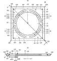
- FIG. 2A is a plan view of the actuator 11 according to the first embodiment, and
- FIG. 2B is a cross-sectional view taken along the line AA.
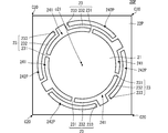
- FIG. 3 is a plan view of an actuator having a conventional configuration.
- FIG. 4 is a plan view of the actuator according to the second embodiment.
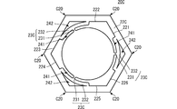
- FIG. 5 is a plan view of the actuator according to the third embodiment.
- FIG. 6 is a plan view of the actuator according to the fourth embodiment.
- FIG. 1 is an exploded perspective view of the fluid control device 10 including the actuator 11 according to the first embodiment.
- FIG. 2A is a plan view of the actuator 11 according to the first embodiment, and
- FIG. 2B is a cross-sectional view taken along the line AA.
- FIG. 3 is a plan view of an actuator having a conventional configuration. In FIGS. 2A and 3, the description of the drive body is omitted. Further, in each figure, in order to make the configurations of the actuator 11 and the fluid control device 10 easy to understand, the shapes of the respective components are exaggerated partially or as a whole.
- the actuator 11 includes a flat plate member 20 and a drive body 30.
- the drive body 30 is, for example, a piezoelectric element, and is mounted on the flat plate member 20. More specifically, the drive body 30 is mounted on the main surface 201 of the central flat plate 21 of the flat plate member 20, which will be described in detail later.
- the flat plate member 20 is made of a metal plate or the like, and has a main surface 201 and a main surface 202.
- the flat plate member 20 includes a central flat plate 21, a frame body 22, and a plurality of connecting members 23.
- the central flat plate 21, the frame body 22, and the plurality of connecting members 23 are integrally formed by using, for example, one flat plate.
- the central flat plate 21 is a flat plate, and the shape of the central flat plate 21 in a plan view (shape seen in the thickness direction (z-axis direction)) is circular. As described above, the drive body 30 is mounted on the main surface 201 of the central flat plate 21.
- the central flat plate 21 corresponds to the "first flat plate" of the present invention.
- the frame body 22 is a flat plate, and the shape of the frame body 22 in a plan view is a square.
- An opening is formed in the frame body 22.
- the opening penetrates the flat plate constituting the frame 22 in the thickness direction (z-axis direction).
- the opening is square in plan view.
- the shape of the opening is similar to the outer shape of the frame body 22, and the center of the frame body 22 and the center of the opening coincide with each other.
- the close pairs of the corners C20 of the frame 22 and the corners C24 of the openings are in the same direction with respect to this center.
- the frame body 22 includes four inner peripheral ends 221, 222, 223, 224.
- the inner peripheral end 221 and the inner peripheral end 223 are parallel, the inner peripheral end 222 and the inner peripheral end 224 are parallel, the inner peripheral end 221 and the inner peripheral end 223, and the inner peripheral end 222 and the inner peripheral end 224. Is orthogonal to.
- One end of the inner peripheral end 221 is connected to one end of the inner peripheral end 222, the other end of the inner peripheral end 222 is connected to one end of the inner peripheral end 223, and the other end of the inner peripheral end 223 is the inner end.
- the connection portion of these inner peripheral ends becomes the corner portion C24 of the above-mentioned opening.
- the central flat plate 21 is arranged inside the opening of the frame body 22. At this time, the center of the opening coincides with the center o21 of the central flat plate 21. Since the area of the central flat plate 21 is smaller than the area of the opening of the frame body 22, even if the central flat plate 21 is arranged inside the opening of the frame body 22, it is between the outer peripheral end of the central flat plate 21 and the frame body 22. Leaves an opening.
- the plurality of connecting members 23 each have a beam shape.
- the plurality of connecting members 23 are arranged in the opening between the central flat plate 21 and the frame body.
- the plurality of connecting members 23 are arranged at intervals along the outer circumference of the central flat plate 21.
- the central flat plate 21 is supported in a state where bending vibration is possible with respect to the frame body 22 via a plurality of connecting members 23.
- Each of the plurality of connecting members 23 includes a first portion 231 and a second portion 232, and a third portion 233.
- the first portion 231 has a shape extending along the radial direction r. As shown in FIG. 2B, the radial direction r is a direction toward the outside from the center o21 of the central flat plate 21.
- the second portion 232 has an arc shape extending along the outer circumference of the central flat plate 21.
- the third portion 233 has a shape extending along the radial direction r.
- One end of the first portion 231 in the extending direction is connected to the outer peripheral end of the central flat plate 21.
- the other end of the first portion 231 in the extending direction is connected to approximately the center of the second portion 232 in the extending direction.
- Both ends of the second portion 232 in the extending direction are connected to different inner peripheral ends via the third portion 233.
- one end of one second portion 232 is connected to the inner peripheral end 221 and the other end is connected to the inner peripheral end 222.
- One end of one second portion 232 connects to the inner peripheral end 222 and the other end connects to the inner peripheral end 223.
- One end of one second portion 232 connects to the inner peripheral end 223 and the other end connects to the inner peripheral end 224.
- One end of one second portion 232 connects to the inner peripheral end 224 and the other end connects to the inner peripheral end 221.
- the plurality of connecting members 23 have an opening 241 configured to include a region on the central flat plate 21 side of the second portion 232 and an opening of a region on the frame body 22 side of the second portion 232.
- the central flat plate 21 and the frame body 22 are connected so as to have 242.
- the opening 242 has a shape including the corner portion C24 of the opening, and a larger opening area than the conventional configuration can be realized without increasing the shape of the frame body 22.
- the opening on the frame body 22P side with respect to the second portion 232 is arcuate along the second portion 232.
- the distance (opening width) w242 between the second portion 232 and the corner portion C24 of the opening is the width w232 of the second portion 232. Greater than.
- the area of the opening 242 of the flat plate member 20 of the present application is larger than the area of the opening 242P of the conventional flat plate member 20. Further, except for both ends in the extending direction of the second portion 232, the separation distance between the second portion 232 and the frame body 22 is larger than the separation distance between the conventional second portion 232 and the frame body 22P.
- the opening 242 is easy to form, and the width of the second portion 232 is particularly large when one flat plate is processed to form the opening 242, and particularly when one metal plate is etched to form the opening 242.
- the opening 242 can be formed while suppressing the narrowing. That is, in the conventional configuration, as in the configuration of the present invention, if an attempt is made to reliably form the opening 242P without changing the shape of the frame body 22P, the width of the second portion 232 becomes narrow. However, by forming the opening 242 as in the present invention, it is possible to prevent the width of the second portion 232 from becoming narrow.
- the flat plate member 20 can easily secure the rigidity required for the connecting member 23, and can be easily miniaturized.
- the rigidity required for the connecting member 23 is, for example, a rigidity that does not break the connecting member 23 up to a predetermined condition when the fluid control device 10 including the flat plate member 20 is dropped.
- the width of the opening 241 (distance between the central flat plate 21 and the second portion 232) w241 is preferably about the same as the width w232 of the second portion 232.
- the outer shape of the flat plate member 20 can be made as small as possible while suppressing the area of the central flat plate 21 from becoming small, and the opening 241 can be formed more reliably.
- each connecting member 23 overlaps with a straight line connecting the center o21 and the corner portion C24. That is, the plurality of connecting members 23 are arranged at equal intervals along the outer circumference of the central flat plate 21.
- the central flat plate 21 can be efficiently supported with respect to the frame body 22.
- the length of the third portion 233 connected to both ends of the second portion 232 can be made the same.
- a support mechanism having good axial symmetry can be realized, and the central flat plate 21 can be supported while preventing vibration leakage to the frame body 22.
- the vibration displacement of the frame body 22 can be suppressed to 10% or less of the central flat plate 21.
- the distance from the connection position to the first portion 231 to the connection to one inner peripheral end of the frame body 22 and the connection position to the first portion 231 to the frame body 22 The distance to connect to one inner peripheral end is the same.
- a support mechanism having good axial symmetry can be realized, and the central flat plate 21 can be supported while preventing vibration leakage to the frame body 22.
- the vibration displacement of the frame body 22 can be suppressed to 10% or less of the central flat plate 21.
- the extending direction of the first portion 231 and the extending direction of the portion connected to the first portion 231 in the second portion 232 are orthogonal to each other.
- the shape of the second portion 232 is the same, the shape of the flat plate member 20 can be made smaller than when the first portion 231 and the second portion 232 are not orthogonal to each other.
- the second portion 232 has a shape along the outer circumference of the central flat plate 21.
- the shape of the flat plate member 20 can be made smaller than the other shapes, assuming that the length of the second portion 232 is the same.
- the fluid control device 10 can be configured by using the actuator 11 having the above configuration.
- the fluid control device 10 includes an actuator 11, a second flat plate 40, and a side wall member 50.
- the second flat plate 40 is arranged on the main surface 202 side of the central flat plate 21, the frame body 22, and the connecting member 23 of the actuator 11.
- the second flat plate 40 includes a plurality of through holes 400.
- the plurality of through holes 400 are arranged at positions overlapping the central flat plate 21 in a plan view.
- the side wall member 50 is an annular shape having a hollow 500, and is arranged between the flat plate member 20 of the actuator 11 and the second flat plate 40.
- the hollow 500 has substantially the same shape as the opening formed by the inner peripheral end of the frame body 22.
- the side wall member 50 is connected to the frame body 22 and the second flat plate 40.
- the pump chamber communicates with the external space on the second flat plate 40 side of the fluid control device 10 by a plurality of through holes 400. Further, the pump chamber communicates with the external space on the actuator 11 side of the fluid control device 10 by the plurality of openings 241 and 242.
- FIG. 4 is a plan view of the actuator according to the second embodiment.
- the actuator and the fluid control device according to the second embodiment are different from the actuator 11 and the fluid control device 10 according to the first embodiment in the configuration of the flat plate member 20A.
- Other configurations of the actuator and the fluid control device according to the second embodiment are the same as those of the actuator 11 and the fluid control device 10 according to the first embodiment, and the description of the same parts will be omitted.
- the flat plate member 20A includes a plurality of connecting members 23A.
- the plurality of connecting members 23A each include a first portion 231 and a second portion 232.
- the plurality of connecting members 23A do not include the third portion 233. That is, both ends of the second portion 232 in the extending direction are directly connected to different inner peripheral ends of the frame body 22, respectively.
- the actuator according to the second embodiment can be made smaller than the actuator 11 according to the first embodiment while exhibiting the same operation and effect as the actuator 11 according to the first embodiment.
- FIG. 5 is a plan view of the actuator according to the third embodiment.
- the actuator and the fluid control device according to the third embodiment are different from the actuator 11 and the fluid control device 10 according to the first embodiment in the configuration of the flat plate member 20B.
- Other configurations of the actuator and the fluid control device according to the third embodiment are the same as those of the actuator 11 and the fluid control device 10 according to the first embodiment, and the description of the same parts will be omitted.
- the frame body 22B is rectangular, and the opening (the portion surrounded by the inner peripheral ends 221, 222, 223, 224) formed by the frame body 22B is also rectangular. Specifically, the length L2 in the direction parallel to the inner peripheral ends 222 and 224 is larger than the length L1 in the direction parallel to the inner peripheral ends 221 and 223.
- the actuator according to the third embodiment can exert the same action and effect as the actuator 11 according to the first embodiment.
- FIG. 6 is a plan view of the actuator according to the fourth embodiment.
- the actuator and the fluid control device according to the fourth embodiment are different from the actuator and the fluid control device according to the second embodiment in the configuration of the flat plate member 20C.
- the other configurations of the actuator and the fluid control device according to the fourth embodiment are the same as those of the actuator and the fluid control device according to the second embodiment, and the description of the same parts will be omitted.
- the frame body 22C is a regular hexagon, and the opening (the portion surrounded by the inner peripheral ends 221, 222, 223, 224, 225, 226) is also a regular hexagon.
- the three connecting members 23C are connected to different inner peripheral ends of the frame body 22C, respectively.
- the second portion 232 of one connecting member 23C is connected to the inner peripheral end 221 and the inner peripheral end 226.
- the second portion 232 of one connecting member 23C is connected to the inner peripheral end 222 and the inner peripheral end 223.
- the second portion 232 of one connecting member 23C is connected to the inner peripheral end 224 and the inner peripheral end 225.
- the actuator according to the fourth embodiment can exert the same action and effect as the actuator according to the second embodiment. That is, the frame is not limited to a square, but may be another regular polygon. Furthermore, the frame is not limited to a regular polygon, but may be a polygon. This configuration is also applied to a configuration in which the corner portion C20 is R-chamfered.
- connection with the frame has a shape with corners.
- these connections may have an R-chamfered shape.
- the configuration in which the side wall member 50 is connected to the main surface 202 side of the frame body is shown.
- another fixing member may be connected to the main surface 201 side of the frame body, or both the main surface 202 side and the main surface 201 side may be connected to the other fixing member.
- Fluid control device 11 Actuator 20: Flat plate member 20A: Flat plate member 20B: Flat plate member 20C: Flat plate member 21: Central flat plate 22, 22B, 22C, 22P: Frame body 23, 23A, 23C: Connecting member 30: Drive body 40: Second flat plate 50: Side wall member 201, 202: Main surface 221, 222, 223, 224, 225, 226: Inner peripheral end 231: First part 232: Second part 233: Third part 241 242, 242P : Opening 400: Through hole 500: Hollow
Landscapes
- Engineering & Computer Science (AREA)
- Mechanical Engineering (AREA)
- General Engineering & Computer Science (AREA)
- Reciprocating Pumps (AREA)
- Apparatuses For Generation Of Mechanical Vibrations (AREA)
- Actuator (AREA)
Priority Applications (4)
| Application Number | Priority Date | Filing Date | Title |
|---|---|---|---|
| JP2022531937A JP7364078B2 (ja) | 2020-06-23 | 2021-06-18 | アクチュエータ、および、流体制御装置 |
| CN202180043966.1A CN115702291A (zh) | 2020-06-23 | 2021-06-18 | 致动器和流体控制装置 |
| US18/063,185 US12467446B2 (en) | 2020-06-23 | 2022-12-08 | Actuator and fluid control apparatus |
| JP2023172425A JP7626180B2 (ja) | 2020-06-23 | 2023-10-04 | アクチュエータ、および、流体制御装置 |
Applications Claiming Priority (2)
| Application Number | Priority Date | Filing Date | Title |
|---|---|---|---|
| JP2020-107697 | 2020-06-23 | ||
| JP2020107697 | 2020-06-23 |
Related Child Applications (1)
| Application Number | Title | Priority Date | Filing Date |
|---|---|---|---|
| US18/063,185 Continuation US12467446B2 (en) | 2020-06-23 | 2022-12-08 | Actuator and fluid control apparatus |
Publications (1)
| Publication Number | Publication Date |
|---|---|
| WO2021261395A1 true WO2021261395A1 (ja) | 2021-12-30 |
Family
ID=79281282
Family Applications (1)
| Application Number | Title | Priority Date | Filing Date |
|---|---|---|---|
| PCT/JP2021/023199 Ceased WO2021261395A1 (ja) | 2020-06-23 | 2021-06-18 | アクチュエータ、および、流体制御装置 |
Country Status (4)
| Country | Link |
|---|---|
| US (1) | US12467446B2 (https=) |
| JP (2) | JP7364078B2 (https=) |
| CN (1) | CN115702291A (https=) |
| WO (1) | WO2021261395A1 (https=) |
Citations (2)
| Publication number | Priority date | Publication date | Assignee | Title |
|---|---|---|---|---|
| WO2016181833A1 (ja) * | 2015-05-08 | 2016-11-17 | 株式会社村田製作所 | ポンプ、流体制御装置 |
| WO2019013164A1 (ja) * | 2017-07-14 | 2019-01-17 | 株式会社村田製作所 | 振動構造、振動装置、および触覚提示装置 |
Family Cites Families (15)
| Publication number | Priority date | Publication date | Assignee | Title |
|---|---|---|---|---|
| JPS6431480A (en) * | 1987-07-27 | 1989-02-01 | Nec Corp | Piezoelectric vibration plate |
| CA2654688C (en) * | 2006-12-09 | 2011-07-26 | Murata Manufacturing Co., Ltd. | Piezoelectric pump |
| JP5170073B2 (ja) * | 2009-12-24 | 2013-03-27 | セイコーエプソン株式会社 | 接合体の形成方法、接合体およびインクジェット記録ヘッド |
| KR101244643B1 (ko) * | 2010-04-30 | 2013-03-18 | 주식회사 리한도어 | 엑추에이터 어셈블리 |
| EP2698537B1 (en) | 2011-04-11 | 2018-10-17 | Murata Manufacturing Co., Ltd. | Actuator-support structure and pump device |
| JP5682513B2 (ja) * | 2011-09-06 | 2015-03-11 | 株式会社村田製作所 | 流体制御装置 |
| JP5692468B2 (ja) * | 2012-08-10 | 2015-04-01 | 株式会社村田製作所 | ブロア |
| TWI552838B (zh) * | 2013-06-24 | 2016-10-11 | 研能科技股份有限公司 | 微型氣壓動力裝置 |
| EP3604810B1 (en) * | 2014-02-21 | 2023-06-28 | Murata Manufacturing Co., Ltd. | Fluid control device and pump |
| WO2016063136A1 (en) * | 2014-10-21 | 2016-04-28 | Handa Hisayuki | System and method for efficient cryogenic carbon dioxide capture from flue gas |
| CN205779588U (zh) * | 2016-06-24 | 2016-12-07 | 研能科技股份有限公司 | 压电致动器结构 |
| WO2019124029A1 (ja) * | 2017-12-22 | 2019-06-27 | 株式会社村田製作所 | ポンプ |
| US11536260B2 (en) * | 2018-09-17 | 2022-12-27 | Microjet Technology Co., Ltd. | Micro-electromechanical system pump |
| CN111629842B (zh) * | 2018-12-27 | 2021-09-10 | 株式会社村田制作所 | 振动构造体和振动产生装置 |
| JP7120196B2 (ja) * | 2019-09-30 | 2022-08-17 | 株式会社村田製作所 | 流体制御装置 |
-
2021
- 2021-06-18 JP JP2022531937A patent/JP7364078B2/ja active Active
- 2021-06-18 CN CN202180043966.1A patent/CN115702291A/zh active Pending
- 2021-06-18 WO PCT/JP2021/023199 patent/WO2021261395A1/ja not_active Ceased
-
2022
- 2022-12-08 US US18/063,185 patent/US12467446B2/en active Active
-
2023
- 2023-10-04 JP JP2023172425A patent/JP7626180B2/ja active Active
Patent Citations (2)
| Publication number | Priority date | Publication date | Assignee | Title |
|---|---|---|---|---|
| WO2016181833A1 (ja) * | 2015-05-08 | 2016-11-17 | 株式会社村田製作所 | ポンプ、流体制御装置 |
| WO2019013164A1 (ja) * | 2017-07-14 | 2019-01-17 | 株式会社村田製作所 | 振動構造、振動装置、および触覚提示装置 |
Also Published As
| Publication number | Publication date |
|---|---|
| US12467446B2 (en) | 2025-11-11 |
| CN115702291A (zh) | 2023-02-14 |
| JP7626180B2 (ja) | 2025-02-04 |
| JP2024001137A (ja) | 2024-01-09 |
| JPWO2021261395A1 (https=) | 2021-12-30 |
| JP7364078B2 (ja) | 2023-10-18 |
| US20230108606A1 (en) | 2023-04-06 |
Similar Documents
| Publication | Publication Date | Title |
|---|---|---|
| EP3109472B1 (en) | Fluid control device and pump | |
| US11725646B2 (en) | Fluid control device | |
| WO2012140967A1 (ja) | アクチュエータ支持構造およびポンプ装置 | |
| US12313054B2 (en) | Fluid control device | |
| JP7400939B2 (ja) | 流体制御装置 | |
| JP7364078B2 (ja) | アクチュエータ、および、流体制御装置 | |
| JP7639897B2 (ja) | アクチュエータ、および、流体制御装置 | |
| US20230140980A1 (en) | Fluid control device | |
| JP7616233B2 (ja) | 流体制御装置 | |
| JP7243829B2 (ja) | 流体制御装置 | |
| WO2024135219A1 (ja) | 流体制御装置 | |
| JP7243830B2 (ja) | 流体制御装置 | |
| WO2025197618A1 (ja) | アクチュエータおよび流体制御装置 | |
| WO2025197617A1 (ja) | アクチュエータおよび流体制御装置 | |
| JP6637862B2 (ja) | 強化レンズマウント | |
| CN114746650B (zh) | 致动器以及流体控制装置 | |
| JP5764110B2 (ja) | 振動モータ | |
| JP7677853B2 (ja) | 超音波トランスデューサ | |
| US20240264428A1 (en) | Mirror device | |
| CN118466008A (zh) | 镜装置 | |
| WO2025121405A1 (ja) | バルブおよび流体制御装置 | |
| WO2025163706A1 (ja) | Memsトランスデューサ | |
| JP2012202571A (ja) | 復水器 | |
| JPWO2021261395A5 (https=) | ||
| JP2007000799A (ja) | 振動抑制装置 |
Legal Events
| Date | Code | Title | Description |
|---|---|---|---|
| 121 | Ep: the epo has been informed by wipo that ep was designated in this application |
Ref document number: 21829753 Country of ref document: EP Kind code of ref document: A1 |
|
| ENP | Entry into the national phase |
Ref document number: 2022531937 Country of ref document: JP Kind code of ref document: A |
|
| NENP | Non-entry into the national phase |
Ref country code: DE |
|
| 122 | Ep: pct application non-entry in european phase |
Ref document number: 21829753 Country of ref document: EP Kind code of ref document: A1 |