WO2021260810A1 - 検出装置及び乗客コンベア - Google Patents
検出装置及び乗客コンベア Download PDFInfo
- Publication number
- WO2021260810A1 WO2021260810A1 PCT/JP2020/024662 JP2020024662W WO2021260810A1 WO 2021260810 A1 WO2021260810 A1 WO 2021260810A1 JP 2020024662 W JP2020024662 W JP 2020024662W WO 2021260810 A1 WO2021260810 A1 WO 2021260810A1
- Authority
- WO
- WIPO (PCT)
- Prior art keywords
- sensor
- detection
- chain
- signal
- detection light
- Prior art date
- Legal status (The legal status is an assumption and is not a legal conclusion. Google has not performed a legal analysis and makes no representation as to the accuracy of the status listed.)
- Ceased
Links
Images


Classifications
-
- B—PERFORMING OPERATIONS; TRANSPORTING
- B66—HOISTING; LIFTING; HAULING
- B66B—ELEVATORS; ESCALATORS OR MOVING WALKWAYS
- B66B29/00—Safety devices of escalators or moving walkways
Definitions
- the present disclosure relates to a detection device for detecting chain elongation and a passenger conveyor.
- Patent Document 1 describes a device for detecting the elongation of a chain on a passenger conveyor.
- the device described in Patent Document 1 includes a distance sensor.
- the distance sensor is located on the side of the step. The light from the distance sensor is emitted horizontally and hits the side of the step.
- the detection device emits a first sensor that emits a first detection light and outputs a first signal according to the reflected light of the first detection light, and a second detection light that emits the second detection light.
- a second sensor that outputs a second signal according to the reflected light of light, a support device that supports the first sensor and the second sensor, and is attached to and detachable from a specific fixed object provided on the passenger conveyor, and the first sensor.
- a detection means for detecting the elongation of the chain based on the first signal from and the second signal from the second sensor.
- the first detection light is emitted downward from the first sensor so as to pass between the skirt guard and the step placed in the normal position from above while the support device is fixed to the fixing target.
- the second detection light radiates downward from the second sensor at a position away from the skirt guard from the first detection light so as to hit the step placed in the normal position from above with the support device fixed to the fixing target. Will be done.
- the passenger conveyor includes a skirt guard, a step for moving the side of the skirt guard, a chain connected to the step, and a detection device for detecting the elongation of the chain.
- the detection device emits a first sensor that emits the first detection light and outputs a first signal according to the reflected light of the first detection light, and emits a second detection light and the reflected light of the second detection light.
- a second sensor that outputs a second signal according to the above, and a detection means that detects the elongation of the chain based on the first signal from the first sensor and the second signal from the second sensor are provided.
- the first detection light is emitted downward from the first sensor so as to pass between the skirt guard and the step placed in the normal position from above.
- the second detection light is emitted downward from the second sensor at a position away from the skirt guard from the first detection light so as to hit the step arranged at the normal position from above.
- chain elongation can be easily detected even on an existing passenger conveyor.
- FIG. It is a figure which shows the example of the passenger conveyor in Embodiment 1.
- FIG. It is a top view which shows the example of a step and the internal structure of a skirt guard. It is a figure for demonstrating the inspection method of a step chain by a maintenance person. It is a figure which shows the AA cross section of FIG. It is a figure which shows the example of the detection device. It is a top view which shows the state of a step when the step chain is not stretched. It is a figure which shows the example of the signal from the sensor obtained when a step moves in the state shown in FIG. It is a top view which shows the state of a step when an extension occurs in a step chain.
- FIG. 1 is a diagram showing an example of a passenger conveyor according to the first embodiment.
- FIG. 1 shows an escalator as an example of a passenger conveyor.
- Other examples of passenger conveyors, such as moving walkways, are omitted in detail.
- Step 1 moves between the skirt guards 2.
- the inner panel 3 extends diagonally upward from the skirt guard 2.
- the stainless steel or glass panel 4 extends upward from the inner panel 3.
- the passenger on step 1 grabs the moving handrail 5.
- the moving handrail 5 moves along the edge of the panel 4.
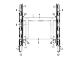
- FIG. 2 is a plan view showing an example of the internal structure of step 1 and the skirt guard 2.
- the passenger conveyor is provided with a pair of step chains 6 for towing step 1.
- a large number of step shafts 7 are provided between the step chains 6.
- Step 1 is provided on each step axis 7.
- a large number of steps 1 are connected to the step chain 6.
- Step 1 includes a tread plate 8, a support frame 9, and a pair of rollers 10. Passengers get on the tread plate 8. A gap G1 is formed between the tread plate 8 and the skirt guard 2.
- the support frame 9 supports the tread plate 8 from below.
- the support frame 9 is fixed to the step shaft 7 below the tread plate 8.
- the roller 10 is rotatably provided on the support frame 9.
- the passenger conveyor is provided with a pair of rails 11 and a pair of rails 12.
- the roller 10 in step 1 rolls on the rail 11. Further, as shown in FIG. 2, a large number of rollers 13 are rotatably provided on the step chain 6. The roller 13 rolls on the rail 12.
- the posture of step 1 is controlled by the rail 11 and the rail 12.
- the roller 13 may be rotatably provided on the step shaft 7.
- the step chain 6 is stretched due to wear or the like. If the step chain 6 is extended, the step 1 may come into contact with the skirt guard 2. Further, if the step 1 comes into contact with the skirt guard 2, the step chain 6 may be damaged. Therefore, the elevator maintenance staff periodically inspects whether or not the step chain 6 is stretched.
- FIG. 3 is a diagram for explaining an inspection method of the step chain 6 by a maintenance person.
- FIG. 3 is a view of the entrance / exit at the bottom of the passenger conveyor as viewed from above.
- the maintenance staff uses a detection device 15 for detecting the elongation of the step chain 6.
- the detection device 15 is a device used by maintenance personnel at various sites. Therefore, it is preferable that the detection device 15 has a size that is easy for maintenance personnel to carry.
- FIG. 4 is a diagram showing a cross section taken along the line AA of FIG.
- FIG. 5 is a diagram showing an example of the detection device 15.
- the detection device 15 includes a sensor 16, a sensor 17, a support device 18, a control device 19, and a notification device 20.
- the sensor 16 is, for example, a reflection type photoelectric sensor.
- the sensor 16 emits the detection light.
- the detection light emitted from the sensor 16 is indicated by an arrow B1.
- the sensor 16 receives the reflected light of the emitted detection light.
- the sensor 16 outputs an on signal according to the received reflected light. For example, the sensor 16 outputs an on signal when it receives a reflected light in an amount larger than a specific threshold value.
- the sensor 17 is, for example, a reflection type photoelectric sensor.
- the sensor 17 emits the detection light.
- the detection light emitted from the sensor 17 is indicated by an arrow B2.
- the sensor 17 receives the reflected light of the emitted detection light.
- the sensor 17 outputs an on signal according to the received reflected light. For example, the sensor 17 outputs an on signal when it receives a reflected light in an amount larger than a specific threshold value.
- the sensor 16 and the sensor 17 are supported by the support device 18.
- the support device 18 can be attached to and detached from, for example, the skirt guard 2. If the skirt guard 2 is made of an iron plate, the support device 18 may include a magnet 18a. As another example, the support device 18 may include a suction cup. 3 and 4 show a state in which the support device 18 is fixed to the skirt guard 2. At least a part of the detection device 15 is arranged directly above step 1.
- step 1 moves to the side of the skirt guard 2.
- the detection light from the sensor 16 is radiated downward from the sensor 16 so as to pass between the skirt guard 2 and the step 1 arranged at the normal position.
- the normal position is a position where step 1 is arranged by design.
- the detection light from the sensor 16 is radiated vertically downward so that the distance L1 from the skirt guard 2 is 0.5 mm.
- the detection light from the sensor 17 is radiated downward from the sensor 17 so as to hit the end of step 1 arranged at the normal position from above.
- the detected light from the sensor 17 passes through a position farther from the skirt guard 2 than the detected light from the sensor 16.
- the detection light from the sensor 17 is radiated vertically downward so that the distance L2 from the skirt guard 2 is 4 mm.
- the control device 19 has a function of detecting the elongation of the step chain 6 based on the on signal from the sensor 16 and the on signal from the sensor 17.
- the control device 19 includes a storage unit 21, a calculation unit 22, a determination unit 23, a detection unit 24, and a notification control unit 25.
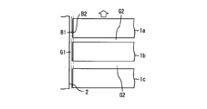
- FIG. 6 is a plan view showing the state of step 1 when the step chain 6 is not stretched.
- step 1 is arranged in the normal position.
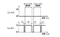
- FIG. 7 is a diagram showing an example of signals from sensors 16 and 17 obtained when step 1 moves in the state shown in FIG. The arrow shown in FIG. 6 indicates the moving direction of step 1.
- step chain 6 If the step chain 6 is not stretched, the detected light from the sensor 16 passes between the skirt guard 2 and the step 1. Therefore, as shown in FIG. 7, the on signal is not output from the sensor 16.
- a gap G2 is formed between adjacent steps 1. If the step chain 6 is not stretched, the steps 1 are arranged at equal intervals. Further, if the step 1 is arranged in the normal position, the detection light from the sensor 17 continues to hit the end portion of the step 1 while the step 1 passes below the detection device 15. Therefore, the on signal is periodically output from the sensor 17 as shown in FIG. That is, the time t0 at which the on signal is output is always constant. Similarly, the time t1 is always constant. The time t1 is the time from when the on signal is no longer output until the next on signal is output.
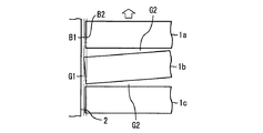
- FIG. 8 is a plan view showing the state of step 1 when the step chain 6 is stretched.
- FIG. 8 shows an example in which the step chains 6 arranged on both sides of the step 1 are stretched.
- FIG. 9 is a diagram showing an example of signals from sensors 16 and 17 obtained when step 1 moves in the state shown in FIG.
- step 1a, step 1b, and step 1c are three consecutive steps in a plurality of steps 1.
- step 1b and step 1c When elongation occurs in the portion of the step chain 6 arranged between step 1b and step 1c, the gap G2 between step 1b and step 1c widens. No inclination occurs in step 1b and step 1c. Therefore, the detection light from the sensor 16 does not hit step 1.
- the detection light from the sensor 16 passes between the skirt guard 2 and step 1. As shown in FIG. 9, the on signal is not output from the sensor 16.
- step 1b the time from when the detection light from the sensor 17 does not hit step 1b to when it hits step 1c becomes long. That is, in the example shown in FIGS. 8 and 9, the time t1 immediately after the passage of step 1b is longer than the time t1 immediately before the passage of step 1b. The time t1 immediately after the passage of step 1b is longer than the time t1 immediately after the passage of step 1c.
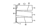
- FIG. 10 is a plan view showing the state of step 1 when the step chain 6 is stretched.
- FIG. 10 shows an example in which the step chain 6 arranged on one side of the step 1 is stretched. Further, FIG. 10 shows an example in which step 1b is tilted so that the right end portion of step 1b is displaced rearward due to the extension of the step chain 6 on one side.
- the direction of step 1 is based on the direction of the person who rides on step 1 while facing the traveling direction.
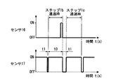
- FIG. 11 is a diagram showing an example of signals from sensors 16 and 17 obtained when step 1 moves in the state shown in FIG.
- step 1b When step 1b is tilted as shown in FIG. 10, when step 1b passes below the detection device 15, the detection light from the sensor 16 hits step 1b. Therefore, when the rear end of step 1b passes below the detection device 15, the on signal is output from the sensor 16.
- the gap G2 between step 1a and step 1b is narrowed, and the gap G2 between step 1b and step 1c is widened. Therefore, the time from when the detection light from the sensor 17 does not hit step 1a to when it hits step 1b is shortened. The time from when the detection light from the sensor 17 does not hit step 1b to when it hits step 1c becomes long. That is, in the example shown in FIGS. 10 and 11, the time t1 immediately before the passage of step 1b is shorter than the time t1 shown in FIG. On the other hand, the time t1 immediately after the passage of step 1b is longer than the time t1 shown in FIG.
- FIG. 12 is a plan view showing the state of step 1 when the step chain 6 is stretched.
- FIG. 12 shows an example in which the step chain 6 arranged on one side of the step 1 is stretched. Further, FIG. 12 shows an example in which step 1b is tilted so that the left end portion of step 1b is displaced rearward due to the extension of the step chain 6 on one side.
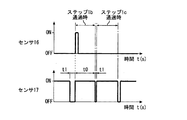
- FIG. 13 is a diagram showing an example of signals from sensors 16 and 17 obtained when step 1 moves in the state shown in FIG.
- step 1b When step 1b is tilted as shown in FIG. 12, when step 1b passes below the detection device 15, the detection light from the sensor 16 hits step 1b. Therefore, when the front end of step 1b passes below the detection device 15, the on signal is output from the sensor 16.
- the gap G2 between step 1a and step 1b widens, and the gap G2 between step 1b and step 1c narrows. Therefore, the time from when the detection light from the sensor 17 does not hit step 1a to when it hits step 1b becomes long.
- the time from when the detection light from the sensor 17 does not hit step 1b to when it hits step 1c is shortened. That is, in the example shown in FIGS. 12 and 13, the time t1 immediately before the passage of step 1b is longer than the time t1 shown in FIG. On the other hand, the time t1 immediately after the passage of step 1b is shorter than the time t1 shown in FIG.
- FIG. 14 is a flowchart showing an operation example of the detection device 15.
- the calculation unit 22 calculates the time when the ON signal is not output from the sensor 17, that is, the time t1 (S101).
- the storage unit 21 stores a specific reference range for time t1.
- the determination unit 23 determines whether or not the time t1 calculated by the calculation unit 22 is within the reference range (S102). For example, the storage unit 21 stores the time t2 as the lower limit value of the time t1.
- the storage unit 21 stores the time t3 as the upper limit value of the time t1. In such a case, the determination unit 23 determines in S102 whether or not the time t1 calculated by the calculation unit 22 satisfies the equation (1). t2 ⁇ t1 ⁇ t3 ... (1)
- step 1 is moving below the detection device 15 in the state shown in FIG. 6, the determination unit 23 determines that the time t1 is within the reference range. When the determination unit 23 determines Yes in S102, it determines whether or not an ON signal is output from the sensor 16 (S103). If step 1 is moving below the detection device 15 in the state shown in FIG. 6, the on signal is not output from the sensor 16. Therefore, it is determined as No in S103. If No is determined in S103, the detection unit 24 does not detect that the step chain 6 is stretched (S104).
- the time t1 calculated by the calculation unit 22 is out of the reference range, it is determined as No in S102.
- step 1 is moving below the detection device 15 in the state shown in FIG. 8, FIG. 10, or FIG. 12, it is determined as No in S102.
- No is determined in S102 immediately after step 1b passes below the detection device 15.
- No is determined in S102 immediately before and immediately after step 1b passes below the detection device 15.
- No is determined in S102 immediately before and immediately after step 1b passes below the detection device 15.
- the detection unit 24 detects the elongation of the step chain 6 (S105).
- the determination unit 23 determines Yes in S103. If it is determined to be Yes in S103, the detection unit 24 detects the elongation of the step chain 6 (S105).
- FIG. 14 shows an example in which the processing of S103 is performed after the processing of S102.
- the processing of S103 may be performed before the processing of S102.
- the determination unit 23 determines whether or not the ON signal is output from the sensor 16 after S101. In this determination, if step 1 is moving below the detection device 15 in the state shown in FIG. 10 or FIG. 12, it is determined to be Yes. On the other hand, if step 1 is moving below the detection device 15 in the state shown in FIG. 8, it is not determined as Yes in this determination. When the step 1 moves below the detection device 15 in the state shown in FIG. 8, the elongation is detected in S105 when the time t1 deviates from the reference range.
- the processing of S102 is performed after the processing of S103, it can be detected separately whether the step chains 6 on both sides are stretched or the step chains 6 on one side are stretched.
- the notification unit 20 notifies that the extension of the step chain 6 is detected by the detection unit 24 (S106).
- the lamp is attached to the support device 18 as the alarm 20.
- the notification control unit 25 turns on the lamp in S106.
- the sensor 16 emits the detection light from above step 1.
- the sensor 17 emits the detection light from above step 1.
- the detection unit 24 detects the elongation of the step chain 6 based on the on signal from the sensor 16 and the on signal from the sensor 17. Therefore, the maintenance staff can detect the elongation of the step chain 6 by attaching the detection device 15 to, for example, the skirt guard 2. With the detection device 15, the elongation of the step chain 6 can be easily detected even with the existing passenger conveyor.
- control device 19 may be provided in other terminals carried by maintenance personnel.
- FIG. 15 is a diagram showing another example of the detection device 15.
- FIG. 15 is a diagram corresponding to the cross section taken along the line AA of FIG.
- the detection device 15 includes a sensor 16, a sensor 17, a support device 18, a control device 19, and a level 26.
- the detection device 15 may further include a notification device 20.
- the support device 18 includes a fixing member 27, a support member 28, and an adjusting mechanism 29.
- the fixing member 27 is removable from the inner panel 3.
- the inner panel 3 is an example of a member extending upward from the skirt guard 2.
- the fixing member 27 may be attached to and detached from a member arranged above the skirt guard 2, for example, the panel 4.
- the support device 18 may be attached to and detached from another fixing target.
- the sensor 16 and the sensor 17 are provided on the support member 28.
- the fixing member 27 and the support member 28 are connected by an adjusting mechanism 29.
- the adjusting mechanism 29 is a mechanism for adjusting the orientation of the support member 28. That is, in the example shown in FIG. 15, with the fixing member 27 fixed to the inner panel 3, the direction of the detection light emitted from the sensor 16 and the direction of the detection light emitted from the sensor 17 are adjusted by the adjusting mechanism 29. Can be adjusted.
- the level 26 is for visually recognizing that the plane orthogonal to the detection light from the sensor 16 is horizontally arranged.
- the detection light from the sensor 16 and the detection light from the sensor 17 are parallel to each other.
- the maintenance staff can confirm by looking at the level 26 that the detection light from the sensor 16 and the detection light from the sensor 17 are radiated vertically downward.
- the detection device 15 may include a level 26.
- the detection device 15 is arranged above the step 1 in which the step 1 moves horizontally.
- the detection device 15 may be arranged above step 1 which moves diagonally upward or diagonally downward.
- the sensor 17 is adjusted so that the on signal is periodically output from the sensor 17 when the step 1 arranged at the normal position passes below the detection device 15.
- each part indicated by reference numerals 21 to 25 indicates a function of the control device 19.
- FIG. 16 is a diagram showing an example of hardware resources of the control device 19.
- the control device 19 includes a processing circuit 30 including, for example, a processor 31 and a memory 32 as hardware resources.
- the function of the storage unit 21 is realized by the memory 32.
- As the memory 32 a semiconductor memory or the like can be adopted.
- the control device 19 realizes the functions of the respective parts shown by the reference numerals 22 to 25 by executing the program stored in the memory 32 by the processor 31.
- FIG. 17 is a diagram showing another example of the hardware resource of the control device 19.
- the control device 19 includes, for example, a processing circuit 30 including a processor 31, a memory 32, and dedicated hardware 33.
- FIG. 17 shows an example in which a part of the functions of the control device 19 is realized by the dedicated hardware 33. All the functions of the control device 19 may be realized by the dedicated hardware 33.
- the dedicated hardware 33 a single circuit, a composite circuit, a programmed processor, a parallel programmed processor, an ASIC, an FPGA, or a combination thereof can be adopted.
Landscapes
- Escalators And Moving Walkways (AREA)
Priority Applications (3)
| Application Number | Priority Date | Filing Date | Title |
|---|---|---|---|
| JP2022519615A JP7097534B2 (ja) | 2020-06-23 | 2020-06-23 | 検出装置及び乗客コンベア |
| CN202080102147.5A CN115916684B (zh) | 2020-06-23 | 2020-06-23 | 检测装置以及乘客输送机 |
| PCT/JP2020/024662 WO2021260810A1 (ja) | 2020-06-23 | 2020-06-23 | 検出装置及び乗客コンベア |
Applications Claiming Priority (1)
| Application Number | Priority Date | Filing Date | Title |
|---|---|---|---|
| PCT/JP2020/024662 WO2021260810A1 (ja) | 2020-06-23 | 2020-06-23 | 検出装置及び乗客コンベア |
Publications (1)
| Publication Number | Publication Date |
|---|---|
| WO2021260810A1 true WO2021260810A1 (ja) | 2021-12-30 |
Family
ID=79282297
Family Applications (1)
| Application Number | Title | Priority Date | Filing Date |
|---|---|---|---|
| PCT/JP2020/024662 Ceased WO2021260810A1 (ja) | 2020-06-23 | 2020-06-23 | 検出装置及び乗客コンベア |
Country Status (3)
| Country | Link |
|---|---|
| JP (1) | JP7097534B2 (https=) |
| CN (1) | CN115916684B (https=) |
| WO (1) | WO2021260810A1 (https=) |
Cited By (1)
| Publication number | Priority date | Publication date | Assignee | Title |
|---|---|---|---|---|
| JP7757494B1 (ja) | 2024-09-17 | 2025-10-21 | 東芝エレベータ株式会社 | 測定装置および測定システム |
Citations (2)
| Publication number | Priority date | Publication date | Assignee | Title |
|---|---|---|---|---|
| JPS62113122U (https=) * | 1986-12-19 | 1987-07-18 | ||
| JP2016016926A (ja) * | 2014-07-08 | 2016-02-01 | 東芝エレベータ株式会社 | 乗客コンベアの間隙異常判定装置 |
Family Cites Families (4)
| Publication number | Priority date | Publication date | Assignee | Title |
|---|---|---|---|---|
| JP6058755B1 (ja) * | 2015-07-09 | 2017-01-11 | 東芝エレベータ株式会社 | 乗客コンベア用チェーン伸び検出装置および乗客コンベア |
| JP6655488B2 (ja) * | 2016-07-06 | 2020-02-26 | 株式会社日立製作所 | 乗客コンベアまたは乗客コンベアのステップの異常検出装置 |
| WO2018229901A1 (ja) * | 2017-06-14 | 2018-12-20 | 三菱電機株式会社 | 乗客コンベア用踏段チェーンの監視システム |
| WO2019016884A1 (ja) * | 2017-07-19 | 2019-01-24 | 三菱電機株式会社 | 乗客コンベアの異常検出装置 |
-
2020
- 2020-06-23 WO PCT/JP2020/024662 patent/WO2021260810A1/ja not_active Ceased
- 2020-06-23 CN CN202080102147.5A patent/CN115916684B/zh active Active
- 2020-06-23 JP JP2022519615A patent/JP7097534B2/ja active Active
Patent Citations (2)
| Publication number | Priority date | Publication date | Assignee | Title |
|---|---|---|---|---|
| JPS62113122U (https=) * | 1986-12-19 | 1987-07-18 | ||
| JP2016016926A (ja) * | 2014-07-08 | 2016-02-01 | 東芝エレベータ株式会社 | 乗客コンベアの間隙異常判定装置 |
Cited By (2)
| Publication number | Priority date | Publication date | Assignee | Title |
|---|---|---|---|---|
| JP7757494B1 (ja) | 2024-09-17 | 2025-10-21 | 東芝エレベータ株式会社 | 測定装置および測定システム |
| JP2026054948A (ja) * | 2024-09-17 | 2026-03-30 | 東芝エレベータ株式会社 | 測定装置および測定システム |
Also Published As
| Publication number | Publication date |
|---|---|
| JP7097534B2 (ja) | 2022-07-08 |
| CN115916684A (zh) | 2023-04-04 |
| CN115916684B (zh) | 2023-07-28 |
| JPWO2021260810A1 (https=) | 2021-12-30 |
Similar Documents
| Publication | Publication Date | Title |
|---|---|---|
| US9181066B2 (en) | Passenger conveyor | |
| JP6170220B1 (ja) | 診断装置 | |
| KR102435681B1 (ko) | 컨베이어 벨트의 마모확인 장치, 화재 예측 시스템, 작업자의 접근 감지 시스템, 자동교정이 가능한 표면상태 검출장치, 및 이를 이용한 컨베이어 벨트의 통합 관리 시스템 | |
| JP6816923B1 (ja) | 異常検出装置 | |
| KR102435683B1 (ko) | 컨베이어 벨트의 마모확인 장치, 화재 예측 시스템, 작업자의 접근 감지 시스템, 자동교정이 가능한 표면상태 검출장치, 및 이를 이용한 컨베이어 벨트의 통합 관리 시스템 | |
| US10766747B2 (en) | Abnormality detection apparatus for passenger conveyor | |
| JP7024046B1 (ja) | 診断システム | |
| JP2012006721A (ja) | 乗客コンベアの安全装置 | |
| JP5660624B2 (ja) | 乗客コンベアの異常検出装置 | |
| JP6692305B2 (ja) | 乗客コンベアの自動隙間測定装置および乗客コンベアの自動隙間測定方法 | |
| JP7097534B2 (ja) | 検出装置及び乗客コンベア | |
| CN109476464A (zh) | 乘客输送机的运行异常检测装置和乘客输送机的运行异常检测方法 | |
| JP2015051836A (ja) | 乗客コンベア | |
| JP6011568B2 (ja) | 乗客コンベアの人検知装置 | |
| JP6878630B1 (ja) | 診断システム | |
| TWI827757B (zh) | 具有用於登記使用者的裝置之乘客運輸系統及用於登記此種乘客運輸系統的使用者之方法 | |
| JP2019089630A (ja) | 乗客コンベア | |
| JP2018039611A (ja) | 乗客コンベア | |
| JP7134155B2 (ja) | ステップ踏板浮き上がり検知装置及びステップ踏板浮き上がり検知システム | |
| JP7114658B2 (ja) | 乗客コンベアのチェーン伸び検出装置及び反射型光センサの設置方法 | |
| CN210794558U (zh) | 一种在线检测输送装置及输送系统 | |
| EP4477609B1 (en) | AUTOMATIC CONVEYOR AND METHOD FOR AUTOMATIC STARTING OF DETERMINING THE PRESENCE OF EXTERNAL OBJECTS ON AN AUTOMATIC CONVEYOR | |
| JP7276993B2 (ja) | 乗客コンベアおよび異常検知方法 | |
| WO2016027342A1 (ja) | 乗客コンベアの手摺異常検出システム | |
| JPH07277657A (ja) | マンコンベア用移動手摺の検査装置 |
Legal Events
| Date | Code | Title | Description |
|---|---|---|---|
| 121 | Ep: the epo has been informed by wipo that ep was designated in this application |
Ref document number: 20941797 Country of ref document: EP Kind code of ref document: A1 |
|
| ENP | Entry into the national phase |
Ref document number: 2022519615 Country of ref document: JP Kind code of ref document: A |
|
| NENP | Non-entry into the national phase |
Ref country code: DE |
|
| 122 | Ep: pct application non-entry in european phase |
Ref document number: 20941797 Country of ref document: EP Kind code of ref document: A1 |