WO2021260764A1 - 空気調和機および空気調和システム - Google Patents
空気調和機および空気調和システム Download PDFInfo
- Publication number
- WO2021260764A1 WO2021260764A1 PCT/JP2020/024362 JP2020024362W WO2021260764A1 WO 2021260764 A1 WO2021260764 A1 WO 2021260764A1 JP 2020024362 W JP2020024362 W JP 2020024362W WO 2021260764 A1 WO2021260764 A1 WO 2021260764A1
- Authority
- WO
- WIPO (PCT)
- Prior art keywords
- failure
- sign
- data
- air
- vibration
- Prior art date
- Legal status (The legal status is an assumption and is not a legal conclusion. Google has not performed a legal analysis and makes no representation as to the accuracy of the status listed.)
- Ceased
Links
Images




Classifications
-
- F—MECHANICAL ENGINEERING; LIGHTING; HEATING; WEAPONS; BLASTING
- F24—HEATING; RANGES; VENTILATING
- F24F—AIR-CONDITIONING; AIR-HUMIDIFICATION; VENTILATION; USE OF AIR CURRENTS FOR SCREENING
- F24F11/00—Control or safety arrangements
- F24F11/30—Control or safety arrangements for purposes related to the operation of the system, e.g. for safety or monitoring
- F24F11/32—Responding to malfunctions or emergencies
-
- F—MECHANICAL ENGINEERING; LIGHTING; HEATING; WEAPONS; BLASTING
- F24—HEATING; RANGES; VENTILATING
- F24F—AIR-CONDITIONING; AIR-HUMIDIFICATION; VENTILATION; USE OF AIR CURRENTS FOR SCREENING
- F24F11/00—Control or safety arrangements
- F24F11/30—Control or safety arrangements for purposes related to the operation of the system, e.g. for safety or monitoring
- F24F11/32—Responding to malfunctions or emergencies
- F24F11/38—Failure diagnosis
Definitions
- the present disclosure relates to an air conditioner and an air conditioner system equipped with a blower that sends air to the air-conditioned space.
- such an air conditioner may be installed in a place where workers do not stay for a long time. Therefore, unlike the air conditioner for home use, it is often difficult for the user to detect the failure of the air conditioner for business use. Therefore, commercial air conditioners are often inspected on a regular basis.
- Failure of the air conditioner includes failure of the compressor, crack of the piping, and failure of the blower motor. Recently, various methods for detecting such various failures have been proposed (see, for example, Patent Document 1).
- blower motor failure not only makes it impossible to perform air conditioning by stopping the air conditioner, but also affects the surroundings by the generation of abnormal noise and abnormal vibration. It ends up.
- One of the causes of blower motor failure is bearing wear. Bearing wear progresses in proportion to the drive time of the fan motor, which causes abnormal noise and abnormal vibration. Conventionally, such abnormalities are confirmed visually and audibly to the air conditioner during regular inspections.
- conventional air conditioners for business use may be installed in warehouses or engine rooms where people do not normally enter, and the air conditioners are regularly inspected only once or twice a year. It may not be possible. In that case, the detection of signs of failure such as abnormal noise and abnormal vibration caused by bearing wear may be delayed, and eventually the air conditioner may stop unexpectedly.
- the present disclosure has been made in view of the above-mentioned problems in the prior art, and an object of the present disclosure is to provide an air conditioner and an air conditioner system capable of detecting a sign of a failure of a blower motor at an early stage.
- the air conditioner according to the present disclosure has a motor, a blower that sends air to the air-conditioned space by driving the motor, a state detection sensor that detects the sound and vibration of the motor as measurement data, and the state detection sensor.
- the noise removing unit that generates state data by removing unnecessary components including information on vibration compares the state data with the initial data that is the state data during normal operation, and based on the comparison result, the above. It has a comparative determination unit for determining whether or not there is a sign of failure of the motor, and a storage unit for storing the initial data.
- the air conditioning system includes the plurality of said air conditioners and a centralized management device for managing the plurality of the air conditioners, and the centralized management device includes state data of the plurality of the air conditioners. Based on the above, it is determined whether or not there is a sign of failure of the motor.
- unnecessary components are removed from the measurement data detected by the state detection sensor to generate state data, and the state data and the initial data are compared. As a result, it is possible to determine whether or not abnormal noise and abnormal vibration have occurred in the motor, so that a sign of failure can be detected at an early stage.
- FIG. It is a circuit diagram which shows an example of the structure of the air conditioner which concerns on Embodiment 1.
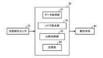
- FIG. It is a functional block diagram which shows an example of the structure of the control device of FIG.
- It is a hardware block diagram which shows an example of the structure of the control device of FIG.
- It is a hardware configuration diagram which shows the other example of the configuration of the control device of FIG.
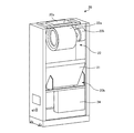
- It is a perspective view which shows an example of the indoor unit of the air conditioner which concerns on Embodiment 1.
- FIG. It is a block diagram which shows an example of the structure of the air conditioning system which concerns on Embodiment 2.
- Embodiment 1 The air conditioner according to the first embodiment will be described.
- the refrigerant is circulated in the refrigerant circuit, and heat is transferred between the outside air and the indoor air through the refrigerant to heat or cool the target space for air conditioning. Is to do.
- FIG. 1 is a circuit diagram showing an example of the configuration of the air conditioner according to the first embodiment.
- the air conditioner 100 includes an outdoor unit 10 and an indoor unit 20.
- a refrigerant circuit in which the refrigerant circulates is configured.
- the compressor 11, the flow path switching device 12, the outdoor heat exchanger 13, the expansion valve 14, and the indoor heat exchanger 21 are connected to each other via a refrigerant pipe.
- the outdoor unit 10 includes a compressor 11, a flow path switching device 12, an outdoor heat exchanger 13, an outdoor blower 15, and an expansion valve 14.
- the compressor 11 sucks in the low-temperature low-pressure refrigerant, compresses the sucked refrigerant, and discharges it in a high-temperature and high-pressure state.
- the compressor 11 is composed of an inverter compressor whose capacity, which is a transmission amount per unit time, is controlled by changing the operating frequency.
- the operating frequency of the compressor 11 is controlled by a control device 30 described later.
- the flow path switching device 12 is, for example, a four-way valve, and switches between cooling operation and heating operation by switching the flow direction of the refrigerant.
- the flow path switching device 12 switches to the state shown by the solid line in FIG. 1, that is, the discharge side of the compressor 11 and the outdoor heat exchanger 13 are connected to each other.
- the flow path switching device 12 switches to the state shown by the broken line in FIG. 1, that is, the suction side of the compressor 11 and the outdoor heat exchanger 13 are connected during the heating operation.
- the switching of the flow path in the flow path switching device 12 is controlled by the control device 30.
- the outdoor heat exchanger 13 is, for example, a fin-and-tube type heat exchanger that exchanges heat between the outdoor air supplied by the outdoor blower 15 and the refrigerant.
- the outdoor heat exchanger 13 functions as a condenser that dissipates the heat of the refrigerant to the outdoor air and condenses the refrigerant during the cooling operation. Further, the outdoor heat exchanger 13 functions as an evaporator that evaporates the refrigerant during the heating operation and cools the outdoor air by the heat of vaporization at that time.
- the outdoor blower 15 is driven by a motor (not shown) to supply outdoor air to the outdoor heat exchanger 13.
- the rotation speed of the outdoor blower 15 is controlled by the control device 30. By controlling the rotation speed, the amount of air blown to the outdoor heat exchanger 13 is adjusted.
- the expansion valve 14 is a throttle device (flow rate control means) and decompresses the refrigerant to expand it.
- the expansion valve 14 is composed of, for example, an electronic expansion valve or a valve capable of controlling the opening degree.
- the opening degree of the expansion valve 14 is controlled by the control device 30.
- the indoor unit 20 has an indoor heat exchanger 21 and an indoor blower 22.
- the indoor heat exchanger 21 exchanges heat between the indoor air supplied by the indoor blower 22 and the refrigerant. As a result, cooling air or heating air supplied to the indoor space is generated.
- the indoor heat exchanger 21 functions as an evaporator during the cooling operation, and cools the air in the air-conditioned space for cooling. Further, the indoor heat exchanger 21 functions as a condenser during the heating operation, and heats the air in the air-conditioned space to heat the room.
- the indoor blower 22 is driven by a fan motor 22b (see FIG. 5) to supply air to the indoor heat exchanger 21.
- the rotation speed of the indoor blower 22 is controlled by the control device 30. By controlling the rotation speed, the amount of air blown to the indoor heat exchanger 21 is adjusted.
- the indoor unit 20 is provided with a state detection sensor 23.
- the state detection sensor 23 is provided in the vicinity of the fan motor 22b of the indoor blower 22 and detects sounds and vibrations generated around the fan motor 22b. The detection result regarding the sound and vibration detected by the state detection sensor 23 is supplied to the control device 30 as measurement data.
- Control device 30 The control device 30 is housed in, for example, an electric component box 24 (see FIG. 5) described later, and controls various devices provided in the outdoor unit 10 and the indoor unit 20.
- the control device 30 may be provided in either the outdoor unit 10 or the indoor unit 20, but in the first embodiment, the control device 30 is provided in the indoor unit 20.
- the control device 30 controls the entire air conditioner 100 including the compressor 11, the flow path switching device 12, the expansion valve 14, the outdoor blower 15, and the indoor blower 22. Further, in the first embodiment, the control device 30 performs failure sign detection processing based on the detection result by the state detection sensor 23. The details of the failure sign detection process will be described later.
- FIG. 2 is a functional block diagram showing an example of the configuration of the control device of FIG.
- the control device 30 includes a data acquisition unit 31, a noise removal unit 32, a comparison determination unit 33, and a storage unit 34.
- the control device 30 is composed of an arithmetic unit such as a microcomputer that realizes various functions by executing software, or hardware such as a circuit device corresponding to various functions.
- the data acquisition unit 31 acquires the sound and vibration detected by the state detection sensor 23 as measurement data.
- the acquired measurement data is supplied to the noise removing unit 32.
- the noise removal unit 32 performs frequency analysis for extracting the frequency component of the measurement data from the measurement data acquired by the data acquisition unit 31. Further, the noise removing unit 32 uses the noise data to remove unnecessary components when detecting a failure sign from the measured data for which frequency analysis has been performed, and generates state data.
- the noise data is data including information on sound and vibration generated from the surrounding environment other than the sound and vibration of the fan motor 22b itself. Details of the noise data and the state data will be described later.
- the comparison determination unit 33 compares the state data, which is the measurement data for which frequency analysis has been performed, with the initial data when performing the failure sign detection process described later. Then, the comparison determination unit 33 determines whether or not there is a sign of failure of the fan motor 22b according to the comparison result.
- the initial data is data showing the sound and vibration of the fan motor 22b itself when the fan motor 22b is operating normally. Details of the initial data will be described later.
- the storage unit 34 stores various information used in each unit of the control device 30.
- the storage unit 34 stores noise data, initial data, and a threshold value.
- the threshold value is a value used when the comparison determination unit 33 determines the presence or absence of a failure sign. The details of the threshold value will be described later.
- FIG. 3 is a hardware configuration diagram showing an example of the configuration of the control device of FIG.
- the control device 30 in FIG. 2 is composed of a processing circuit 41 as shown in FIG.
- each function of the data acquisition unit 31, the noise removal unit 32, the comparison determination unit 33, and the storage unit 34 is realized by the processing circuit 41.
- the processing circuit 41 may be, for example, a single circuit, a composite circuit, a programmed processor, a parallel programmed processor, an ASIC (Application Specific Integrated Circuit), or an FPGA (Field-Programmable Gate). Array), or a combination of these.
- the control device 30 may realize the functions of each of the data acquisition unit 31, the noise removal unit 32, the comparison determination unit 33, and the storage unit 34 by the processing circuit 41, or the functions of each unit may be realized by one processing circuit 41. It may be realized.
- FIG. 4 is a hardware configuration diagram showing another example of the configuration of the control device of FIG.
- the control device 30 of FIG. 2 is composed of a processor 42 and a memory 43 as shown in FIG.
- each function of the data acquisition unit 31, the noise removal unit 32, the comparison determination unit 33, and the storage unit 34 is realized by the processor 42 and the memory 43.
- the functions of the data acquisition unit 31, the noise removal unit 32, the comparison determination unit 33, and the storage unit 34 are realized by software, firmware, or a combination of software and firmware. Will be done.
- the software and firmware are described as a program and stored in the memory 43.
- the processor 42 realizes the functions of each part by reading and executing the program stored in the memory 43.
- Examples of the memory 43 include non-volatile or volatile semiconductor memories such as RAM (RandomAccessMemory), ROM (ReadOnlyMemory), flash memory, EPROM (ErasableandProgrammableROM) and EEPROM (ElectricallyErasableandProgrammableROM). Is used. Further, as the memory 43, for example, a detachable recording medium such as a magnetic disk, a flexible disk, an optical disk, a CD (Compact Disc), an MD (Mini Disc), and a DVD (Digital Versatile Disc) may be used.
- RAM RandomAccessMemory
- ROM ReadOnlyMemory
- flash memory EPROM (ErasableandProgrammableROM) and EEPROM (ElectricallyErasableandProgrammableROM).
- EPROM ErasableandProgrammableROM
- EEPROM ElectricallyErasableandProgrammableROM
- the notification means 40 is connected to the control device 30.
- the notification means 40 notifies the determination result of the failure sign detection process by the comparison determination unit 33 of the control device 30.
- the notification means 40 may be provided in the air conditioner 100, or may be an information terminal such as an external PC (Personal Computer).
- FIG. 5 is a perspective view showing an example of an indoor unit of the air conditioner according to the first embodiment.
- the indoor unit 20 includes an indoor heat exchanger 21, an indoor blower 22, an electric component box 24, and the like inside the housing. Further, an air outlet 20a for blowing out air is provided in the upper part of the indoor unit 20. A suction port 20b for sucking air is provided on the front surface of the indoor unit 20.
- the indoor heat exchanger 21 is arranged so as to incline diagonally upward from the back to the front, and is installed so as to divide the internal space into the suction port 20b side and the air outlet 20a side.
- the indoor blower 22 is, for example, a sirocco fan or a turbo fan, and has a blower element 22a for sending air and a fan motor 22b connected to the blower element 22a.
- the blowing element 22a is for sending out air such as a propeller.
- the fan motor 22b rotates and drives the blower element 22a by the supplied electric power.
- the indoor blower 22 (blower element 22a and fan motor 22b) is arranged on the air outlet 20a side of the indoor heat exchanger 21 and at the upper part in the housing.
- the electric component box 24 is equipped with the above-mentioned control device 30 and various electric components.
- the electrical component box 24 is arranged, for example, in the lower part of the housing below the indoor heat exchanger 21.
- the air conditioner 100 can also perform various operations that can be performed by a general air conditioner such as a dry operation or a ventilation operation.
- the air conditioner 100 is not limited to this example, and can also perform various operations capable of a general air conditioner such as a heating operation, a ventilation operation, and a defrosting operation.
- the flow path switching device 12 is switched to the state shown by the solid line in FIG. That is, the flow path switching device 12 is switched so that the discharge side of the compressor 11 and the outdoor heat exchanger 13 are connected, and the suction side of the compressor 11 and the indoor heat exchanger 21 are connected.
- the high temperature and high pressure gas state refrigerant is discharged from the compressor 11.
- the high-temperature and high-pressure gas refrigerant discharged from the compressor 11 flows into the outdoor heat exchanger 13 that functions as a condenser via the flow path switching device 12.
- the outdoor heat exchanger 13 heat exchange is performed between the high-temperature and high-pressure gas refrigerant that has flowed in and the outdoor air supplied by a blower (not shown).
- a blower not shown
- the high-pressure liquid refrigerant flowing out of the outdoor heat exchanger 13 expands at the expansion valve 14 and becomes a two-phase state refrigerant in which a low-pressure gas refrigerant and a low-pressure liquid refrigerant are mixed.
- the two-phase refrigerant flows into the indoor heat exchanger 21 that functions as an evaporator.
- heat exchange is performed between the flowing two-phase state refrigerant and the heat medium flowing through the heat medium circulation circuit.
- the liquid refrigerant of the two-phase refrigerant evaporates to become a low-pressure gas refrigerant.
- the low-pressure gas refrigerant flowing out of the indoor heat exchanger 21 flows into the compressor 11 via the flow path switching device 12, is compressed, becomes a high-temperature high-pressure gas refrigerant, and is discharged from the compressor 11 again.
- the refrigerant circulates in the refrigerant circuit as shown by the solid line arrow in FIG.
- the flow path switching device 12 is switched to the state shown by the broken line in FIG. That is, the flow path switching device 12 is switched so that the discharge side of the compressor 11 and the indoor heat exchanger 21 are connected, and the suction side of the compressor 11 and the outdoor heat exchanger 13 are connected.
- the high temperature and high pressure gas state refrigerant is discharged from the compressor 11.
- the high-temperature and high-pressure gas refrigerant discharged from the compressor 11 flows into the indoor heat exchanger 21 that functions as a condenser via the flow path switching device 12.
- the indoor heat exchanger 21 heat exchange is performed between the high-temperature and high-pressure gas refrigerant that has flowed in and the heat medium that flows through the heat medium circulation circuit.
- the high-temperature and high-pressure gas refrigerant condenses into a high-pressure liquid refrigerant.
- the high-pressure liquid refrigerant flowing out of the indoor heat exchanger 21 expands at the expansion valve 14 and becomes a two-phase state refrigerant in which a low-pressure gas refrigerant and a low-pressure liquid refrigerant are mixed.
- the two-phase refrigerant flows into the outdoor heat exchanger 13 that functions as an evaporator.
- heat exchange is performed between the flowing two-phase state refrigerant and the outdoor air supplied by a blower (not shown).
- the liquid refrigerant of the two-phase refrigerant evaporates to become a low-pressure gas refrigerant.
- the low-pressure gas refrigerant flowing out of the outdoor heat exchanger 13 flows into the compressor 11 via the flow path switching device 12, is compressed, becomes a high-temperature and high-pressure gas refrigerant, and is discharged from the compressor 11 again.
- the refrigerant circulates in the refrigerant circuit as shown by the broken line arrow in FIG.
- one of the failures of the air conditioner 100 is the failure of the fan motor 22b of the indoor blower 22, and the cause of the failure is, for example, the wear of the bearing.
- the bearing wears abnormal noise and abnormal vibration are generated from the fan motor 22b.
- Sound and vibration have unique frequency components, and if the two sounds and vibrations are the same, the frequency components of the two sounds and vibrations are also the same. On the other hand, if the two sounds and vibrations are not the same, that is, they contain different sound and vibration components, the frequency components of the two sounds and vibrations will be different. That is, the sound and vibration generated by the failure of the fan motor 22b have different frequency components as compared with the sound and vibration during normal operation. Therefore, it is possible to determine the change from the normal operation of the fan motor 22b based on the frequency components of the sound and vibration generated by the fan motor 22b.
- the fan motor 22b fails and abnormal noise and abnormal vibration occur, the signal level of the sound and vibration becomes higher than that in the normal operation. Therefore, it is possible to determine the presence or absence of abnormal noise and abnormal vibration based on the magnitude of the signal level of sound and vibration.
- the presence or absence of a failure sign of the fan motor 22b can be determined based on the information on the frequency components of sound and vibration. Therefore, in the first embodiment, the sound and vibration generated by the fan motor 22b are detected, and based on the frequency information obtained from the measurement data as the detection result, air conditioning such as a failure of the fan motor 22b of the indoor blower 22 is performed. Detects a sign of failure of the machine 100.
- the failure sign detection process is performed by the control device 30. First, the data acquisition unit 31 of the control device 30 acquires the sound and vibration detected by the state detection sensor 23 as measurement data.
- the measurement data obtained by using the state detection sensor 23 includes not only the sound and vibration generated from the fan motor 22b but also the sound and vibration generated from the surrounding environment as external noise.
- the failure sign detection process is performed using the measurement data including unnecessary components such as external noise, the sound and vibration of the fan motor 22b itself cannot be discriminated. Therefore, the accuracy of detecting the failure sign of the fan motor 22b is lowered. Therefore, the noise removing unit 32 removes unnecessary components including external noise from the acquired measurement data.
- Noise data is used when removing unnecessary components from measurement data.
- Noise data is data that includes sound and vibration information about external noise.
- the noise data is data including information on the sound and vibration of the surrounding environment obtained by using the state detection sensor 23 in a state where the fan motor 22b (air conditioner 100) is stopped.
- the noise data is obtained by performing frequency analysis on the data obtained by using the state detection sensor 23.
- the noise removal unit 32 When removing unnecessary components from the measurement data, the noise removal unit 32 performs frequency analysis on the measurement data and extracts the frequency components of the measurement data. Then, the noise removing unit 32 subtracts the noise data read from the storage unit 34 from the measurement data obtained by the frequency analysis. As a result, only the external noise component is removed from the measurement data, and the state data including only the frequency component for the sound and vibration of the fan motor 22b is generated.
- the comparison determination unit 33 compares the state data and the initial data for each of sound and vibration. Then, the comparison determination unit 33 determines whether or not there is a sign of failure of the fan motor 22b based on the comparison result.
- the initial data is data obtained by removing external noise from the measurement data detected by the state detection sensor 23 when the fan motor 22b is operating normally, such as at the time of installation.
- the initial data is stored in advance in the storage unit 34 in a state where the frequency analysis has been performed.
- the threshold value stored in advance in the storage unit 34 is used.
- the threshold value is a value set for the magnitude of the frequency component in the state data.
- the threshold is set, for example, to 10% of the magnitude of each frequency component in the initial data.
- the comparison determination unit 33 In both sound and vibration, the comparison determination unit 33 normally operates the fan motor 22b when the difference between the magnitude of each frequency component in the state data and the magnitude of each frequency component in the initial data is equal to or less than the threshold value. Judge that That is, in this case, the comparison determination unit 33 determines that the fan motor 22b has "no failure sign".
- the comparison determination unit 33 determines that the fan motor 22b is normal when the difference between the magnitude of each frequency component in the state data and the magnitude of each frequency component in the initial data exceeds the threshold value in both sound and vibration. Judges that it behaves differently. That is, in this case, the comparison determination unit 33 determines that the fan motor 22b has "a sign of failure".
- the comparison determination unit 33 is not a clear failure sign when the difference between the magnitude of each frequency component in the state data and the magnitude of each frequency component in the initial data exceeds the threshold value in either sound or vibration. However, it is judged that there is a possibility of leading to a failure sign. That is, the subfold, the comparison determination unit 33 determines that the fan motor 22b is a "grace of failure sign".
- the control device 30 When it is determined that there is a sign of failure, the control device 30 notifies by the notification means 40 that there is a sign of failure of the fan motor 22b at the time when it is determined that there is a sign of failure. Further, when it is determined that "the grace of the failure sign", the control device 30 notifies by the notification means 40 that the failure sign may occur, for example, at the time of periodic inspection.
- unnecessary components are removed from the measurement data detected by the state detection sensor 23 to generate state data, and the state data and the initial data are compared. To. By comparing the state data and the initial data in this way, it is possible to determine whether or not abnormal noise and abnormal vibration have occurred in the fan motor 22b, so that a sign of failure can be detected at an early stage. Can be done.
- the air conditioner 100 as a result of comparison between the state data and the initial data, if the difference between the size of the state data and the initial data is equal to or less than the threshold value in both sound and vibration, it is determined that there is no sign of failure. Further, when the difference exceeds the threshold value in both sound and vibration, it is judged that there is a sign of failure. Further, when the difference exceeds the threshold value in either sound or vibration, it is judged to be a grace of failure sign. As described above, in the first embodiment, it is possible to determine the presence or absence of a failure sign of the fan motor 22b only by comparing the state data and the initial data with respect to the sound and the vibration.
- the notification means 40 When the air conditioner 100 determines that there is a sign of failure, the notification means 40 is used to notify that there is a sign of failure. Further, when it is determined that the failure sign is a grace period, the notification means 40 is used to notify that the failure sign may occur at the time of inspection. As a result, when there is a possibility of failure, it is immediately notified that there is a sign of failure, and although it does not lead to failure immediately, if there is a possibility of failure, it is notified at the time of inspection. Will be done. Therefore, the failure sign of the fan motor 22b can be appropriately notified to the operator as needed.
- noise data including information on sound and vibration generated from the surrounding environment when unnecessary components are removed from the measurement data is used.
- the sound and vibration caused by something other than the fan motor 22b included in the measurement data are removed, so that the sound and vibration of the fan motor 22b itself can be appropriately extracted.
- Embodiment 2 Next, the second embodiment will be described.
- the measurement data detected by the respective air conditioners 100 are compared and the failure sign detection process is performed. It differs from the first embodiment.
- the same reference numerals are given to the parts common to the first embodiment, and detailed description thereof will be omitted.
- FIG. 6 is a block diagram showing an example of the configuration of the air conditioning system according to the second embodiment.
- the air conditioner system 1000 includes a plurality of air conditioners 100 and a centralized management device 200 for managing these air conditioners 100.
- the centralized management device 200 includes a management side control device 210.
- the management side control device 210 is connected to the control devices 30 of the plurality of air conditioners 100, and performs failure sign detection processing based on the measurement data measured by the plurality of air conditioners 100.
- failure sign detection processing The failure sign detection process according to the second embodiment will be described.
- the failure sign detection process is performed by the management side control device 210 of the centralized management device 200.
- the management side control device 210 receives the state data generated by the control device 30 of each air conditioner 100. Then, the management side control device 210 compares the received state data, and determines whether or not there is a failure sign of the fan motor 22b based on the comparison result.
- the data are compared using the threshold value as in the first embodiment.
- the threshold value in this case is set to 10% of the size of each frequency component in the reference state data, for example, with reference to the state data in a certain air conditioner 100.
- the management side control device 210 determines that there is no sign of failure when the difference between the two state data is equal to or less than the threshold value in both sound and vibration. Further, the management side control device 210 determines that "there is a failure sign" when the difference between the two state data exceeds the threshold value in both sound and vibration. Further, when the difference between the two state data exceeds the threshold value in either sound or vibration, the management side control device 210 determines that it is a "grace of failure sign".
- the failure sign detection process may be performed by a method of comparing the state data and the initial data as described in the first embodiment. This makes it possible to more reliably detect a failure sign of the fan motor 22b.
- the air conditioning system 1000 it is determined whether or not there is a sign of failure of the fan motor 22b based on the state data of the plurality of air conditioners 100. As a result, it is possible to determine whether or not there is a failure sign of the fan motor 22b without preparing initial data which is state data during normal operation, so that failure sign detection processing can be easily performed. ..
- the present disclosure is not limited to the above-described embodiments 1 and 2, and various modifications and applications can be made without departing from the gist of the present disclosure. It is possible.
- the failure sign detection process is described as being performed on the fan motor 22b of the indoor blower 22, but this is not limited to this example.
- the failure sign detection process can also be performed on, for example, the fan motor of the outdoor blower 15 provided in the outdoor unit 10.
Landscapes
- Engineering & Computer Science (AREA)
- Chemical & Material Sciences (AREA)
- Combustion & Propulsion (AREA)
- Mechanical Engineering (AREA)
- General Engineering & Computer Science (AREA)
- Health & Medical Sciences (AREA)
- Biomedical Technology (AREA)
- Air Conditioning Control Device (AREA)
Priority Applications (2)
| Application Number | Priority Date | Filing Date | Title |
|---|---|---|---|
| PCT/JP2020/024362 WO2021260764A1 (ja) | 2020-06-22 | 2020-06-22 | 空気調和機および空気調和システム |
| JP2022531257A JPWO2021260764A1 (cg-RX-API-DMAC7.html) | 2020-06-22 | 2020-06-22 |
Applications Claiming Priority (1)
| Application Number | Priority Date | Filing Date | Title |
|---|---|---|---|
| PCT/JP2020/024362 WO2021260764A1 (ja) | 2020-06-22 | 2020-06-22 | 空気調和機および空気調和システム |
Publications (1)
| Publication Number | Publication Date |
|---|---|
| WO2021260764A1 true WO2021260764A1 (ja) | 2021-12-30 |
Family
ID=79282690
Family Applications (1)
| Application Number | Title | Priority Date | Filing Date |
|---|---|---|---|
| PCT/JP2020/024362 Ceased WO2021260764A1 (ja) | 2020-06-22 | 2020-06-22 | 空気調和機および空気調和システム |
Country Status (2)
| Country | Link |
|---|---|
| JP (1) | JPWO2021260764A1 (cg-RX-API-DMAC7.html) |
| WO (1) | WO2021260764A1 (cg-RX-API-DMAC7.html) |
Cited By (4)
| Publication number | Priority date | Publication date | Assignee | Title |
|---|---|---|---|---|
| CN114413055A (zh) * | 2022-01-20 | 2022-04-29 | 济南轨道交通集团有限公司 | 一种地铁隧道风机连锁风阀的运维装置和方法 |
| CN114857762A (zh) * | 2022-03-01 | 2022-08-05 | 青岛海尔空调器有限总公司 | 用于控制空调的方法及装置、空调 |
| CN116734393A (zh) * | 2023-05-19 | 2023-09-12 | 青岛海尔空调器有限总公司 | 用于控制空调器的方法及装置、空调器、存储介质 |
| KR102754728B1 (ko) * | 2024-02-16 | 2025-01-22 | 오토시맨틱스 주식회사 | 공기조화기의 이상여부를 감지하는 방법 및 장치 |
Families Citing this family (1)
| Publication number | Priority date | Publication date | Assignee | Title |
|---|---|---|---|---|
| CN115095953B (zh) * | 2022-06-16 | 2024-04-09 | 青岛海信日立空调系统有限公司 | 一种故障诊断模型的训练方法及装置 |
Citations (5)
| Publication number | Priority date | Publication date | Assignee | Title |
|---|---|---|---|---|
| JPH0599475A (ja) * | 1991-10-08 | 1993-04-20 | Daikin Ind Ltd | 空気調和機における騒音診断装置 |
| JP2004125641A (ja) * | 2002-10-03 | 2004-04-22 | Toshiba Eng Co Ltd | 異常音検出装置 |
| JP2004132683A (ja) * | 2002-08-09 | 2004-04-30 | Daikin Ind Ltd | 故障診断システム、検診装置、及びデータサーバ |
| JP2019060539A (ja) * | 2017-09-26 | 2019-04-18 | 株式会社富士通ゼネラル | 空気調和装置 |
| WO2019186663A1 (ja) * | 2018-03-26 | 2019-10-03 | 三菱電機株式会社 | 診断装置および閾値作成方法 |
Family Cites Families (2)
| Publication number | Priority date | Publication date | Assignee | Title |
|---|---|---|---|---|
| JPH07103540A (ja) * | 1993-09-30 | 1995-04-18 | Mitsubishi Electric Corp | データ収集装置および空気調和システムのメンテナンスツール |
| JP7056164B2 (ja) * | 2018-01-18 | 2022-04-19 | マツダ株式会社 | ドライバ状態判定装置 |
-
2020
- 2020-06-22 WO PCT/JP2020/024362 patent/WO2021260764A1/ja not_active Ceased
- 2020-06-22 JP JP2022531257A patent/JPWO2021260764A1/ja active Pending
Patent Citations (5)
| Publication number | Priority date | Publication date | Assignee | Title |
|---|---|---|---|---|
| JPH0599475A (ja) * | 1991-10-08 | 1993-04-20 | Daikin Ind Ltd | 空気調和機における騒音診断装置 |
| JP2004132683A (ja) * | 2002-08-09 | 2004-04-30 | Daikin Ind Ltd | 故障診断システム、検診装置、及びデータサーバ |
| JP2004125641A (ja) * | 2002-10-03 | 2004-04-22 | Toshiba Eng Co Ltd | 異常音検出装置 |
| JP2019060539A (ja) * | 2017-09-26 | 2019-04-18 | 株式会社富士通ゼネラル | 空気調和装置 |
| WO2019186663A1 (ja) * | 2018-03-26 | 2019-10-03 | 三菱電機株式会社 | 診断装置および閾値作成方法 |
Cited By (5)
| Publication number | Priority date | Publication date | Assignee | Title |
|---|---|---|---|---|
| CN114413055A (zh) * | 2022-01-20 | 2022-04-29 | 济南轨道交通集团有限公司 | 一种地铁隧道风机连锁风阀的运维装置和方法 |
| CN114413055B (zh) * | 2022-01-20 | 2024-04-16 | 济南轨道交通集团有限公司 | 一种地铁隧道风机连锁风阀的运维装置和方法 |
| CN114857762A (zh) * | 2022-03-01 | 2022-08-05 | 青岛海尔空调器有限总公司 | 用于控制空调的方法及装置、空调 |
| CN116734393A (zh) * | 2023-05-19 | 2023-09-12 | 青岛海尔空调器有限总公司 | 用于控制空调器的方法及装置、空调器、存储介质 |
| KR102754728B1 (ko) * | 2024-02-16 | 2025-01-22 | 오토시맨틱스 주식회사 | 공기조화기의 이상여부를 감지하는 방법 및 장치 |
Also Published As
| Publication number | Publication date |
|---|---|
| JPWO2021260764A1 (cg-RX-API-DMAC7.html) | 2021-12-30 |
Similar Documents
| Publication | Publication Date | Title |
|---|---|---|
| CN207395264U (zh) | 制冷循环装置以及制冷循环系统 | |
| JP6797278B2 (ja) | 冷凍サイクル装置及び冷凍サイクルシステム | |
| JP6143977B1 (ja) | 冷凍サイクル装置及び冷凍サイクルシステム | |
| JP6253853B1 (ja) | 冷凍サイクル装置 | |
| CN112105876A (zh) | 制冷剂泄漏判定装置、空调机以及制冷剂泄漏判定方法 | |
| KR102701595B1 (ko) | 공기 조화기 및 그 제어 방법 | |
| US12152798B2 (en) | Air-conditioning apparatus | |
| US11397021B2 (en) | Outdoor unit, indoor unit, and air conditioner | |
| JPWO2019244280A1 (ja) | 空気調和装置および運転状態判定方法 | |
| JP7433043B2 (ja) | 空気調和システム | |
| JP2015005677A (ja) | 電子機器装置およびその筐体 | |
| JP6815377B2 (ja) | 空気調和機用ユニット及び空気調和機 | |
| JP2010190484A (ja) | 電子機器冷却装置 | |
| CN106642530A (zh) | 控制方法及空调器 | |
| JP7668902B2 (ja) | 空調システムおよび空調管理システム | |
| JPH11248300A (ja) | 空気調和装置 | |
| JPWO2020049633A1 (ja) | 空気調和機の室外機 | |
| JP2021139580A (ja) | 給気システム | |
| JP7471521B2 (ja) | 冷凍サイクル装置 | |
| JP7499981B2 (ja) | 冷凍サイクル装置 | |
| KR20210113153A (ko) | 공기 조화기 | |
| WO2019198176A1 (ja) | 空気調和装置の室内機 | |
| WO2024038532A1 (ja) | 空気調和機 | |
| CN121701982A (zh) | 空气源热泵空调机组 | |
| KR20250179162A (ko) | 공기조화기 및 그 제어 방법 |
Legal Events
| Date | Code | Title | Description |
|---|---|---|---|
| 121 | Ep: the epo has been informed by wipo that ep was designated in this application |
Ref document number: 20942115 Country of ref document: EP Kind code of ref document: A1 |
|
| ENP | Entry into the national phase |
Ref document number: 2022531257 Country of ref document: JP Kind code of ref document: A |
|
| NENP | Non-entry into the national phase |
Ref country code: DE |
|
| 122 | Ep: pct application non-entry in european phase |
Ref document number: 20942115 Country of ref document: EP Kind code of ref document: A1 |