WO2021256303A1 - 着座検知装置、着座検知方法、及び、プログラム - Google Patents
着座検知装置、着座検知方法、及び、プログラム Download PDFInfo
- Publication number
- WO2021256303A1 WO2021256303A1 PCT/JP2021/021384 JP2021021384W WO2021256303A1 WO 2021256303 A1 WO2021256303 A1 WO 2021256303A1 JP 2021021384 W JP2021021384 W JP 2021021384W WO 2021256303 A1 WO2021256303 A1 WO 2021256303A1
- Authority
- WO
- WIPO (PCT)
- Prior art keywords
- transmitter
- seating
- detection device
- vehicle
- space
- Prior art date
- Legal status (The legal status is an assumption and is not a legal conclusion. Google has not performed a legal analysis and makes no representation as to the accuracy of the status listed.)
- Ceased
Links
Images


Classifications
-
- B—PERFORMING OPERATIONS; TRANSPORTING
- B60—VEHICLES IN GENERAL
- B60R—VEHICLES, VEHICLE FITTINGS, OR VEHICLE PARTS, NOT OTHERWISE PROVIDED FOR
- B60R21/00—Arrangements or fittings on vehicles for protecting or preventing injuries to occupants or pedestrians in case of accidents or other traffic risks
- B60R21/01—Electrical circuits for triggering passive safety arrangements, e.g. airbags, safety belt tighteners, in case of vehicle accidents or impending vehicle accidents
- B60R21/015—Electrical circuits for triggering passive safety arrangements, e.g. airbags, safety belt tighteners, in case of vehicle accidents or impending vehicle accidents including means for detecting the presence or position of passengers, passenger seats or child seats, and the related safety parameters therefor, e.g. speed or timing of airbag inflation in relation to occupant position or seat belt use
- B60R21/01512—Passenger detection systems
- B60R21/0153—Passenger detection systems using field detection presence sensors
-
- B—PERFORMING OPERATIONS; TRANSPORTING
- B60—VEHICLES IN GENERAL
- B60N—SEATS SPECIALLY ADAPTED FOR VEHICLES; VEHICLE PASSENGER ACCOMMODATION NOT OTHERWISE PROVIDED FOR
- B60N2/00—Seats specially adapted for vehicles; Arrangement or mounting of seats in vehicles
- B60N2/002—Seats provided with an occupancy detection means mounted therein or thereon
- B60N2/0021—Seats provided with an occupancy detection means mounted therein or thereon characterised by the type of sensor or measurement
-
- B—PERFORMING OPERATIONS; TRANSPORTING
- B60—VEHICLES IN GENERAL
- B60R—VEHICLES, VEHICLE FITTINGS, OR VEHICLE PARTS, NOT OTHERWISE PROVIDED FOR
- B60R21/00—Arrangements or fittings on vehicles for protecting or preventing injuries to occupants or pedestrians in case of accidents or other traffic risks
-
- G—PHYSICS
- G01—MEASURING; TESTING
- G01S—RADIO DIRECTION-FINDING; RADIO NAVIGATION; DETERMINING DISTANCE OR VELOCITY BY USE OF RADIO WAVES; LOCATING OR PRESENCE-DETECTING BY USE OF THE REFLECTION OR RERADIATION OF RADIO WAVES; ANALOGOUS ARRANGEMENTS USING OTHER WAVES
- G01S15/00—Systems using the reflection or reradiation of acoustic waves, e.g. sonar systems
- G01S15/02—Systems using the reflection or reradiation of acoustic waves, e.g. sonar systems using reflection of acoustic waves
- G01S15/04—Systems determining presence of a target
-
- G—PHYSICS
- G01—MEASURING; TESTING
- G01S—RADIO DIRECTION-FINDING; RADIO NAVIGATION; DETERMINING DISTANCE OR VELOCITY BY USE OF RADIO WAVES; LOCATING OR PRESENCE-DETECTING BY USE OF THE REFLECTION OR RERADIATION OF RADIO WAVES; ANALOGOUS ARRANGEMENTS USING OTHER WAVES
- G01S15/00—Systems using the reflection or reradiation of acoustic waves, e.g. sonar systems
- G01S15/02—Systems using the reflection or reradiation of acoustic waves, e.g. sonar systems using reflection of acoustic waves
- G01S15/06—Systems determining the position data of a target
- G01S15/08—Systems for measuring distance only
-
- B—PERFORMING OPERATIONS; TRANSPORTING
- B60—VEHICLES IN GENERAL
- B60N—SEATS SPECIALLY ADAPTED FOR VEHICLES; VEHICLE PASSENGER ACCOMMODATION NOT OTHERWISE PROVIDED FOR
- B60N2210/00—Sensor types, e.g. for passenger detection systems or for controlling seats
- B60N2210/10—Field detection presence sensors
- B60N2210/26—Ultrasonic, e.g. sonar
-
- B—PERFORMING OPERATIONS; TRANSPORTING
- B60—VEHICLES IN GENERAL
- B60R—VEHICLES, VEHICLE FITTINGS, OR VEHICLE PARTS, NOT OTHERWISE PROVIDED FOR
- B60R21/00—Arrangements or fittings on vehicles for protecting or preventing injuries to occupants or pedestrians in case of accidents or other traffic risks
- B60R21/01—Electrical circuits for triggering passive safety arrangements, e.g. airbags, safety belt tighteners, in case of vehicle accidents or impending vehicle accidents
- B60R21/015—Electrical circuits for triggering passive safety arrangements, e.g. airbags, safety belt tighteners, in case of vehicle accidents or impending vehicle accidents including means for detecting the presence or position of passengers, passenger seats or child seats, and the related safety parameters therefor, e.g. speed or timing of airbag inflation in relation to occupant position or seat belt use
- B60R21/01512—Passenger detection systems
- B60R21/0153—Passenger detection systems using field detection presence sensors
- B60R21/01536—Passenger detection systems using field detection presence sensors using ultrasonic waves
Definitions
- This disclosure relates to a technique for detecting the presence or absence of personnel or the presence or absence of sitting.
- Patent Documents 1 to 4 Conventionally, a technique for detecting the presence or absence of personnel or the presence or absence of sitting is known (see, for example, Patent Documents 1 to 4).
- Japanese Unexamined Patent Publication No. 2006-69454 Japanese Unexamined Patent Publication No. 11-15970 Japanese Unexamined Patent Publication No. 2000-16233 Japanese Unexamined Patent Publication No. 2019-138671
- Patent Documents 1 and 2 has a problem that it is necessary to embed sensors for each seat to be detected. Further, the technique described in Patent Document 3 has a problem that one set of sensors can detect only the presence or absence of one seat. Further, the technique described in Patent Document 4 has a problem that the memory load is relatively high because it is necessary to perform image processing using a camera.
- this disclosure is made in view of the above problem, and it is not necessary to embed a sensor for each seat to be detected, and one set of sensors can be used to determine whether or not there are two or more seats or whether or not there are seats. It is an object of the present invention to provide a seating detection device that can be detected and does not require image processing using a camera.
- the seating detection device is arranged in a space having a plurality of seats, and has one or more receivers for receiving sounds generated in or outside the space, and the one or more receivers.
- the acoustic characteristic analysis unit that calculates the time characteristic or frequency characteristic of the sound in the space from the signal received by the receiver, and the time characteristic or the frequency characteristic calculated by the acoustic characteristic analysis unit. It is equipped with a detection unit that detects the presence or absence of personnel or the presence or absence of seating and outputs the detection result.
- the seating detection method is a seating detection method performed by a seating detection device including one transmitter, one or more receivers, an acoustic characteristic analysis unit, and a detection unit.
- One transmitter sequentially transmits a predetermined sound in space
- the one or more receivers sequentially receive a reflected wave of the predetermined sound transmitted by the one transmitter, and the acoustic characteristics.
- the analysis unit shows each of a transmission signal showing the waveform of the predetermined sound transmitted by the one transmitter and a reflected wave waveform of the predetermined sound received by the one or more receivers 1.
- the detection unit calculates by the acoustic characteristic analysis unit.
- the program according to one aspect of the present disclosure is a program for causing a seating detection device including one transmitter, one or more receivers, an acoustic characteristic analysis unit, and a detection unit to execute a seating detection process.
- the one transmitter sequentially transmits a predetermined sound in the space
- the one or more receivers reflect the predetermined sound transmitted by the one transmitter.
- Waves are sequentially received
- the acoustic characteristic analysis unit receives a transmission signal indicating the waveform of the predetermined sound transmitted by the one transmitter, and the predetermined sound received by the one or more receivers.
- the time characteristic or frequency characteristic of the sound in the vehicle interior space in the vehicle by the predetermined sound is sequentially calculated, and the detection unit.
- the time characteristic or frequency characteristic of the sound in the vehicle interior space due to the predetermined sound transmitted by the transmitter at the first timing calculated by the acoustic characteristic analysis unit, and the second by the transmitter Based on the difference between the time characteristic and the frequency characteristic of the sound in the vehicle interior space due to the predetermined sound transmitted at the timing, the presence / absence of personnel or the presence / absence of seating in the space is detected, and the detection result is output. Including processing.
- the seating detection device it is not necessary to embed sensors for each seat to be detected, and one set of sensors has the presence or absence of two or more seats or seating.
- a seating detection device that can detect the presence or absence of a seat and does not require image processing using a camera.
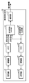
- FIG. 1 is a block diagram showing a configuration of a seating detection device according to the first embodiment.
- FIG. 2 is a plan view schematically showing a state in which the seating detection device according to the first embodiment is installed in the vehicle.
- FIG. 3 is a waveform diagram showing an example of a transmission signal according to the first embodiment.
- FIG. 4 is a waveform diagram showing an example of an impulse response generated by the acoustic characteristic analysis unit according to the first embodiment.
- FIG. 5 is a block diagram showing a configuration of a detection unit according to the first embodiment.
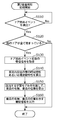
- FIG. 6 is a flowchart of the first seating detection process according to the first embodiment.
- FIG. 7 is a block diagram showing the configuration of the seating detection device according to the second embodiment.
- FIG. 8 is a block diagram showing the configuration of the seating detection device according to the third embodiment.
- FIG. 9 is a block diagram showing the configuration of the seating detection device according to the fourth embodiment.
- FIG. 10 is a plan view schematically showing a vehicle equipped with the seating detection device according to the fourth embodiment.
- FIG. 11 is a schematic diagram showing an example of the correspondence between the learning model according to the fourth embodiment, the teacher data used for the training, the conditions satisfied by the teacher data, and the correct answer label attached to the teacher data.
- FIG. 12 is a flowchart of the second seating detection process according to the fourth embodiment.
- the seating detection device is arranged in a space having a plurality of seats, and has one or more receivers for receiving sounds generated in or outside the space, and the one or more receivers.
- the acoustic characteristic analysis unit that calculates the time characteristic or frequency characteristic of the sound in the space from the signal received by the receiver, and the time characteristic or the frequency characteristic calculated by the acoustic characteristic analysis unit. It is equipped with a detection unit that detects the presence or absence of personnel or the presence or absence of seating and outputs the detection result.
- the presence or absence of personnel or the presence or absence of seating in the space is reflected in the time characteristics or frequency characteristics of the sound in the space having a plurality of seats.
- the seating detection device it is not necessary to embed sensors for each seat to be detected, and it is possible to detect the presence or absence of two or more seats or the presence or absence of seating with one set of sensors.
- a seating detection device that does not require image processing using a camera.
- the space includes one transmitter that transmits a predetermined sound
- the one or more receivers receive the reflected wave of the predetermined sound
- the acoustic characteristic analysis unit receives the predetermined sound.
- the time characteristic or the frequency characteristic of the predetermined sound is calculated from the sound signal of the above and the signal received by the one or more receivers, and the detection unit is calculated by the acoustic characteristic analysis unit.
- the presence / absence of the personnel or the presence / absence of the seat may be detected based on the difference between the characteristic or the frequency characteristic.
- the movement is a relatively minute movement such as a movement of a person accompanying breathing.
- the time characteristic or the frequency characteristic corresponding to the first timing and the time characteristic or the frequency characteristic corresponding to the second timing calculated by the acoustic characteristic analysis unit.
- the sound transmitted by the one transmitter may be ultrasonic waves.
- the one transmitter may be located at a place where sound can be transmitted to all the seats in the space.
- the space is an internal space in the vehicle, and at least one of the one transmitter and the one or more receivers is a place deviated from the center line extending in the traveling direction of the vehicle.
- the one transmitter may not be located at a position of line symmetry with respect to the center line as the target axis with respect to at least one of the one or more receivers.
- the reception timing of the reflected wave by the person can be different from each other. Therefore, it is possible to distinguish between one of the above two seats and the other seat and detect the presence or absence of seating.
- the space is a vehicle
- the seat arrangement is symmetrically installed, it is possible to detect the presence or absence of personnel or seating in all seats.
- the space may be a vehicle, and the one transmitter and the one or more receivers may be located in the overhead console of the vehicle.
- the seating detection device is in a position overlooking all seats, so that it is possible to more effectively detect the presence or absence of personnel or seating.
- the one or more receivers are a plurality of receivers
- the acoustic characteristic analysis unit is at least two of a plurality of received signals indicating the waveform of the reflected wave received by the plurality of receivers.
- the time characteristic or the frequency characteristic is calculated by performing the directivity control using one.
- the detection unit further includes the time characteristic or the frequency characteristic of the predetermined sound transmitted by the one transmitter at the first timing calculated by the acoustic characteristic analysis unit, and the transmitter. If there is a difference of a predetermined value or more between the time characteristic or the frequency characteristic due to the predetermined sound transmitted at the second timing, the time characteristic or the frequency characteristic in which the difference is generated is generated.
- the seating position may be calculated from the position on the time axis in.
- the one transmitter and at least one of the one or more receivers may be a speaker and a microphone used in the vehicle emergency call system, respectively.
- the detection unit uses the communication device used in the vehicle emergency call system to transmit the detected information regarding the presence or absence of sitting in the space to the emergency call center linked with the vehicle emergency call system. You may do so.
- the seating detection method is a seating detection method performed by a seating detection device including one transmitter, one or more receivers, an acoustic characteristic analysis unit, and a detection unit.
- One transmitter sequentially transmits a predetermined sound in space
- the one or more receivers sequentially receive a reflected wave of the predetermined sound transmitted by the one transmitter, and the acoustic characteristics.
- the analysis unit shows each of a transmission signal showing the waveform of the predetermined sound transmitted by the one transmitter and a reflected wave waveform of the predetermined sound received by the one or more receivers 1.
- the detection unit calculates by the acoustic characteristic analysis unit.
- the presence or absence of personnel or the presence or absence of seating in the space is reflected in the time characteristics or frequency characteristics of the sound in the space having a plurality of seats.
- a seating detection device that does not require image processing using a camera is provided.
- the program according to one aspect of the present disclosure is a program for causing a seating detection device including one transmitter, one or more receivers, an acoustic characteristic analysis unit, and a detection unit to execute a seating detection process.
- the one transmitter sequentially transmits a predetermined sound in the space
- the one or more receivers reflect the predetermined sound transmitted by the one transmitter.
- Waves are sequentially received
- the acoustic characteristic analysis unit receives a transmission signal indicating the waveform of the predetermined sound transmitted by the one transmitter, and the predetermined sound received by the one or more receivers.
- the time characteristic or frequency characteristic of the sound in the vehicle interior space in the vehicle by the predetermined sound is sequentially calculated, and the detection unit.
- the time characteristic or frequency characteristic of the sound in the vehicle interior space due to the predetermined sound transmitted by the transmitter at the first timing calculated by the acoustic characteristic analysis unit, and the second by the transmitter Based on the difference between the time characteristic and the frequency characteristic of the sound in the vehicle interior space due to the predetermined sound transmitted at the timing, the presence / absence of personnel or the presence / absence of seating in the space is detected, and the detection result is output. Including processing.
- the presence or absence of personnel or the presence or absence of seating in the space is reflected in the time characteristic or frequency characteristic of the sound in the space having a plurality of seats.
- the comprehensive or specific embodiment of the present disclosure may be realized by a recording medium such as a system, a method, an integrated circuit, a computer program or a computer-readable CD-ROM, and the system, the method, the integrated circuit, the computer. It may be realized by any combination of a program and a recording medium.
- This seating detection device is installed in a space having a plurality of seats, and detects the presence or absence of personnel or the presence or absence of seating in the space.
- the space having a plurality of seats may be, for example, a vehicle which is a passenger car, a vehicle for a large number of passengers, a bus, a train, an aircraft, an indoor space, or the like.
- a space having a plurality of seats will be described as a vehicle that is a passenger car.
- the space having a plurality of seats does not have to be limited to a vehicle that is a passenger car.
- FIG. 1 is a block diagram showing a configuration of a seating detection device 10 according to a first embodiment.
- the seating detection device 10 includes a transmitter 11, a receiver 12, an acoustic characteristic analysis unit 13, a detection unit 14, an amplifier 15, an amplifier 16, and an ADC 17 (ADC: Analog to Digital). It includes a Converter), a DAC 18 (DAC: Digital to Analog Converter), and a transmission signal generation unit 19.
- ADC Analog to Digital
- DAC Digital to Analog Converter
- the transmitter 11 converts the input electric signal into a sound, and transmits the converted sound into the vehicle in which the seating detection device 10 is installed.
- the sound converted by the transmitter 11 that is, the sound transmitted by the transmitter 11 will be described as ultrasonic waves, but the sound transmitted by the transmitter is not necessarily limited to ultrasonic waves. There is no need to.
- the transmitter 11 is realized by, for example, a speaker. Further, the transmitter 11 may be realized by, for example, a piezoelectric element. The transmitter 11 transmits a predetermined ultrasonic wave by inputting a transmission signal described later.
- the receiver 12 receives the sound transmitted by the transmitter 11 and its reflected wave, converts the received sound and its reflected wave into a received signal composed of an analog electric signal, and outputs the converted received signal. ..
- the sound received by the receiver 12 and its reflected wave will be described as ultrasonic waves, but the sound received by the receiver 12 and its reflected wave are not necessarily ultrasonic waves. It does not have to be limited to.
- the receiver 12 is realized by, for example, a microphone. Further, the receiver 12 may be realized by, for example, a piezoelectric element. When the transmitter 11 and the receiver 12 are realized by a piezoelectric element, the transmitter 11 and the receiver 12 may be realized by a single piezoelectric element that operates in a time-division manner.
- the seating detection device 10 is described here as having one receiver 12, the seating detection device 10 is not necessarily limited to the configuration including one receiver, and the seating detection device 10 is not necessarily limited to the configuration including one receiver. It may be configured to include.
- FIG. 2 is a plan view schematically showing how the seating detection device 10 is installed in the vehicle 30.
- FIG. 2 illustrates a part of the structure in the vehicle 30, which cannot be directly visually recognized, as if it can be visually recognized.
- the seating detection device 10 is installed in the overhead console 32 located on the ceiling of the vehicle 30. More specifically, the seating detection device 10 is installed in the overhead console 32 at a position deviated from the center line extending in the traveling direction of the vehicle 30.
- the seating detection device 10 By installing the seating detection device 10 at the above position, the distance until the ultrasonic wave transmitted from the transmitter 11 is reflected by the seat 31A and reaches the receiver 12, and the ultrasonic wave transmitted from the transmitter 11 Is reflected by the seat 31B and reaches the receiver 12, the ultrasonic wave transmitted from the transmitter 11 is reflected by the seat 31C and reaches the receiver 12, and the distance from the transmitter 11
- the distance from which the transmitted ultrasonic waves are reflected by the seat 31D to reach the receiver 12 can be different from each other.
- the transmission signal generation unit 19 generates a transmission signal indicating a predetermined ultrasonic waveform output by the transmitter 11, and outputs the generated transmission signal to the acoustic characteristic analysis unit 13 and the DAC 18.
- the transmission signal generation unit 19 will be described as generating a transmission signal composed of a digital signal.
- the transmission signal generation unit 19 is realized, for example, by a microprocessor (not shown) included in the seating detection device 10 executing a program stored in a memory (not shown) included in the seating detection device 10.
- FIG. 3 is a waveform diagram showing an example of a transmission signal output by the transmission signal generation unit 19.
- the horizontal axis is time
- the vertical axis in the waveform shown on the upper side is the amplitude of the transmission signal
- the vertical axis in the waveform shown on the lower side is the frequency of the transmission signal.
- the transmission signal is an 86 ms signal consisting of a 43 ms signaled period consisting of a sweep sine wave signal and a 43 ms non-signal period.
- the transmission signal generation unit 19 continuously and sequentially outputs a transmission signal including a signaled period and a non-signal period.
- the DAC 18 converts a transmission signal, which is a digital signal generated by the transmission signal generation unit 19, into an analog signal, and outputs a transmission signal composed of the converted analog signal to the amplifier 16.
- the amplifier 16 amplifies the transmission signal converted into an analog signal by the DAC 18, and outputs the amplified transmission signal to the transmitter 11. As a result, the transmitter 11 transmits a predetermined ultrasonic wave. As described above, the transmission signal generation unit 19 continuously outputs sequential transmission signals. Therefore, the transmitter 11 continuously and sequentially transmits predetermined ultrasonic waves.
- the amplifier 15 amplifies the received signal consisting of the analog signal output from the receiver 12, and outputs the amplified received signal to the ADC 17.
- the ADC 17 converts the received signal composed of the amplified analog signal output from the amplifier 16 into a digital signal, and outputs the received signal composed of the converted digital signal to the acoustic characteristic analysis unit 13.
- predetermined ultrasonic waves are continuously and sequentially transmitted from the transmitter 11. Therefore, the receiver 12 continuously and sequentially receives a predetermined ultrasonic wave and its reflected wave. Therefore, the received signals corresponding to each of the predetermined ultrasonic waves transmitted from the transmitter 11 are continuously and sequentially output from the ADC 17.
- the acoustic characteristic analysis unit 13 calculates the time characteristic or frequency characteristic of the sound in the space inside the vehicle 30, that is, the space having a plurality of seats, from the signal received by the receiver 12. More specifically, the acoustic characteristic analysis unit 13 inputs each of the transmission signals sequentially output from the transmission signal generation unit 19 and each of the received signals sequentially output from the ADC 17, and the transmission signal is sequentially input. For each of the above, the impulse response of a predetermined ultrasonic wave in the vehicle 30 is sequentially calculated from the transmission signal and the reception signal corresponding to the transmission signal, and the calculated impulse response is sequentially output to the detection unit 14.
- the impulse response of a predetermined ultrasonic wave in the vehicle 30 calculated by the acoustic characteristic analysis unit 13 is an example of the time characteristic or the frequency characteristic of the sound in the space in the vehicle 30.
- the time characteristic or frequency characteristic of the sound in the vehicle 30 calculated by the acoustic characteristic analysis unit 13 will be described as being the impulse response of a predetermined ultrasonic wave in the vehicle 30, but the acoustic characteristic analysis unit 13 calculates.
- the time characteristic or frequency characteristic of sound in the vehicle 30 is not necessarily limited to the impulse response of a predetermined ultrasonic wave in the vehicle 30.
- the acoustic characteristic analysis unit 13 is realized by, for example, a microprocessor (not shown) included in the seating detection device 10 executing a program stored in a memory (not shown) included in the seating detection device 10.
- FIG. 4 is a waveform diagram showing an example of the impulse response generated by the acoustic characteristic analysis unit 13.
- the horizontal axis is time and the vertical axis is signal level.
- the positions of the reflection components by the seat 31D on the time axis are different from each other. This is because, as described above, the distance until the ultrasonic wave transmitted from the transmitter 11 is reflected by the seat 31A and reaches the receiver 12, and the ultrasonic wave transmitted from the transmitter 11 is reflected by the seat 31B.
- the position on the time axis in the impulse response corresponds to the length of the path from the transmitter to the place where the movement of the person is occurring to the receiver.
- the acoustic characteristic analysis unit 13 Fourier transforms the transmitted signal and the received signal, calculates the ratio of the signal strength for each frequency to the transmitted signal and the received signal after the Fourier transform, and calculates each frequency.
- the impulse response may be calculated by performing an inverse Fourier transform on the ratio of the signal strength.
- the detection unit 14 detects the presence or absence of personnel or the presence or absence of seating in the vehicle 30 based on the time characteristics or frequency characteristics of the sound in the space inside the vehicle 30 calculated by the acoustic characteristic analysis unit 13, and outputs the detection result. do. More specifically, the detection unit 14 receives an impulse response sequentially calculated by the acoustic characteristic analysis unit 13, and the impulse response of a predetermined ultrasonic wave transmitted by the transmitter 11 at the first timing (hereinafter, "" The vehicle is based on the difference between the "first impulse response") and the impulse response of a predetermined ultrasonic wave transmitted by the transmitter at the second timing (hereinafter, also referred to as "second impulse response").
- the detection unit 14 is realized, for example, by a microprocessor (not shown) included in the seating detection device 10 executing a program stored in a memory (not shown) included in the seating detection device 10.
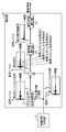
- FIG. 5 is a block diagram showing the configuration of the detection unit 14.
- FIG. 5 is superimposed on a schematic waveform diagram of signals output from the main components of the detection unit 14.
- the horizontal axis is time and the vertical axis is signal level.
- the detection unit 14 includes an impulse response holding unit 21, a difference calculation unit 22, an absolute value calculation unit 23, and a change position calculation unit 24.
- the impulse response holding unit 21 stores each of the impulse responses sequentially calculated by the acoustic characteristic analysis unit 13.
- the difference calculation unit 22 sets the newly input impulse response as the first impulse response, and the impulse response is stored by the impulse response holding unit 21.
- One of them for example, the impulse response input immediately before the first impulse response
- the difference signal indicating the difference is output to the absolute value calculation unit 23.
- the positions of the reflection components by the seat 31D on the time axis are different from each other. Therefore, for example, when a person is seated in the seat 31A, the movement of the person (for example, the movement accompanying breathing) determines the position on the time axis of the reflection component by the seat 31A in the difference signal. There is a difference of more than the value.
- the position of the seat is located at the position on the time axis in the difference signal, which is a difference of a predetermined value or more generated in the difference signal. It will be reflected.
- the absolute value calculation unit 23 calculates the absolute value of the input difference signal, and calculates the change position of the difference absolute value signal indicating the absolute value of the calculated difference signal. Output to unit 24.
- the change position calculation unit 24 detects sitting in the vehicle 30 based on the difference absolute value signal, and outputs detection information indicating the detection result. More specifically, the change position calculation unit 24 detects that there is seating when a difference of a predetermined value or more occurs in the difference absolute value signal, outputs seating information indicating that there is seating, and determines. When there is no difference greater than or equal to the value, no seating is detected and seating information indicating no seating is output.
- the change position calculation unit 24 determines the seating position from the position on the time axis in the difference absolute value signal in which the difference occurs.
- the calculated and output seating information includes information indicating the calculated seating position.
- the change position calculation unit 24 is not limited to calculating the seating information only by one difference absolute value signal, and may use the average value, the maximum value, the change frequency, and the like of the past multiple times difference absolute value signal. .. Moreover, you may judge by machine learning using these information as a feature quantity.
- Correct answer label for whether or not each of the data of a large number of difference absolute value signals such as the difference absolute value signal acquired in the past, the average value, the maximum value, and the change frequency of the difference absolute value signal of multiple times in the past is seated in the learning phase.
- a learning model is constructed using the data with the above as teacher data, and the trained model is output.
- at least one of the difference absolute value signal acquired by the seating detection device, the average value, the maximum value, and the change frequency of the difference absolute value signals of the past multiple times is input to the trained model generated as input information.
- the machine learning algorithm is not particularly limited as long as the above output result is achieved. For example, it may be typically used for supervised learning such as logistic regression or support vector machine, or it may be deep learning using a neural network that can discover features by itself.
- the seating detection device 10 having the above configuration performs a first seating detection process for detecting seating in the vehicle 30.
- FIG. 6 is a flowchart of the first seating detection process.
- a transmission signal is output from the transmission signal generation unit 19 in a state where the impulse response calculated by the acoustic characteristic analysis unit 13 in the past is stored in the impulse response holding unit 21. It will be started.
- the transmitter 11 transmits a predetermined ultrasonic wave into the vehicle 30 (step S10).
- the receiver 12 When a predetermined ultrasonic wave is transmitted from the transmitter 11, the receiver 12 receives the ultrasonic wave and the reflected wave of the ultrasonic wave, and outputs a received signal (step S20).
- the acoustic characteristic analysis unit 13 uses a predetermined ultrasonic vehicle from the transmission signal output by the transmission signal generation unit 19 and the reception signal output by the receiver 12.
- the impulse response within 30 is calculated (step S30), and the calculated impulse response is output.
- the difference calculation unit 22 uses the impulse response as the first impulse response and is stored in the impulse response holding unit 21 by the acoustic characteristic analysis unit 13 in the past.
- the calculated impulse response is used as the second impulse response, the difference between the first impulse response and the second impulse response is calculated, and a difference signal indicating the calculated difference is output.
- the absolute value calculation unit 23 calculates the absolute value of the difference signal output from the difference calculation unit 22, and outputs the difference absolute value signal indicating the absolute value of the calculated difference signal (step S40).
- the change position calculation unit 24 checks whether or not the difference of the predetermined value or more is generated in the difference absolute value signal (step S50).
- step S50 when a difference of a predetermined value or more occurs (step S50: Yes), the change position calculation unit 24 further determines the position on the time axis in the absolute value difference signal where the difference occurs. From, the seating position is calculated (step S60). Then, the change position calculation unit 24 outputs the fact that there is seating and the seating information indicating the seating position (step S70).
- step S50 when a difference of a predetermined value or more does not occur (step S50: No), the change position calculation unit 24 outputs a seating signal indicating that there is no seating (step S80).
- step S70 When the process of step S70 is completed and the process of step S80 is completed, the seating detection device 10 ends the first seating detection process.
- the seating detection device 10 having the above configuration, it is not necessary to embed sensors (transmitter 11 and receiver 12 here) for each seat (here, seats 31A to 31D) to be detected.
- one set of sensors here, transmitter 11 and receiver 12
- the seating detection device 10 calculates the impulse response in the vehicle 30 by ultrasonic waves.
- ultrasonic waves have less noise in the vehicle than sound waves. Therefore, the seating detection device 10 can detect the presence / absence of a person or the presence / absence of a seat with higher accuracy than the seating detection device having a configuration for calculating an impulse response in a vehicle by sound waves.
- the seating detection device 10 detects the presence / absence of personnel or the presence / absence of seating depending on the presence / absence of movement of a person. Therefore, it is possible to detect the presence / absence or sitting of a person regardless of the shape and posture of the person. Furthermore, it is possible to suppress erroneous detection of the presence / absence of personnel or the presence / absence of seating due to a non-moving object such as luggage placed on a seat.
- the seating detection device 10 does not need to embed sensors for each seat to be detected. Therefore, it is possible to detect the presence / absence of personnel or the presence / absence of seating regardless of the deformation of the seat (for example, the deformation of the shape of the seat from the shape of the chair to the shape of the mat), the storage state of a part of the seat, and the like. ..
- the seating detection device 10 can detect the presence / absence of personnel or the presence / absence of seating even in an area that cannot be directly visually recognized from the installation position.
- the seating detection device 10 can output, for example, the calculated seating signal to an ECU (Electronic Control Unit) that controls the vehicle 30.
- ECU Electronic Control Unit
- the ECU that controls the vehicle 30 can prevent, for example, the airbag from being unnecessarily opened with respect to a seat that is not seated.
- the ECU that controls the vehicle 30 can, for example, turn off the seat heater for a seat that is not seated to suppress battery consumption.
- the ECU that controls the vehicle 30 can suppress unnecessary air conditioning from the air conditioner, for example, for a seat that is not seated.
- This seating detection device is a vehicle corresponding to the vehicle emergency call system (hereinafter, also referred to as "vehicle according to the second embodiment"), that is, a vehicle provided with a speaker, a microphone, and a communication device used in the vehicle emergency call system. Will be installed in.
- vehicle emergency call system is, for example, e-Call.
- FIG. 7 is a block diagram showing the configuration of the seating detection device 10A according to the second embodiment.
- the transmitter 11 is changed to the transmitter 51
- the receiver 12 is changed to the receiver 52
- the detection unit 14 is changed from the seating detection device 10 according to the first embodiment. Is changed to the detection unit 14A.
- the transmitter 51 is a speaker used in an emergency call system and has the same function as the transmitter 11. That is, the transmitter 51 is shared as a transmitter of the seating detection device 10A and as a speaker used in the emergency call system.
- the receiver 52 is a microphone used in the emergency call system and has the same function as the receiver 12. That is, the receiver 52 is shared as a receiver of the seating detection device 10A and as a microphone used in the emergency call system.
- the detection unit 14A has the following additional functions in addition to the functions of the detection unit 14.
- the additional function is the presence / absence or seating of personnel in the vehicle according to the second embodiment, which is detected by using the communication device 50 used in the vehicle emergency call system when a predetermined condition is satisfied. It is a function to send information related to the presence or absence to the emergency call center.
- the predetermined condition may be, for example, a condition in which it is determined by the emergency call system that the vehicle according to the second embodiment has caused an accident, or, for example, by the emergency call system, the second embodiment. It may be a condition that it is determined that the person who gets on the vehicle has a sudden illness.
- the speaker and the microphone are shared between the seating detection device 10A and the emergency call system. Therefore, the number of speakers and the number of microphones mounted on the vehicle according to the second embodiment can be suppressed.
- an emergency situation has occurred, such as when the vehicle according to the second embodiment causes an accident, or when a person riding on the vehicle according to the second embodiment suddenly becomes ill.
- information regarding the presence or absence of personnel or the presence or absence of seating can be transmitted to the emergency call center.
- FIG. 8 is a block diagram showing the configuration of the seating detection device 10B according to the second embodiment.
- the receiver 12 is changed from the receiver 12A to the receiver 12N, and the amplifier 15 is changed from the amplifier 15A to the amplifier 15N.
- the ADC 17 is changed to ADC 17A to ADC 17N, and the directivity control unit 60 is added to the configuration.
- Each of the receiver 12A to the receiver 12N has the same function as the receiver 12.
- the amplifiers 15A to 15N each have the same function as the amplifier 15.
- Each of ADC17A to ADC17N has the same function as ADC17.
- the number of receivers 12 is changed from 1 to K
- the number of amplifiers 15 is changed from 1 to K
- the number of ADCs 17 is changed from 1 to K from the seating detection device 10. It is modified and configured as follows.
- K is shown as if it is an integer of 3 or more in FIG. 8, if K is an integer of 2 or more, it is not necessarily an integer of 3 or more as shown in FIG. It does not have to be limited to.
- the directivity control unit 60 is specified by inputting K received signals output from each of the ADCs 17A to 17N and performing directivity control using at least two of the input K received signals.
- the received signal emphasizing the reflected wave component from the direction of is calculated, and the calculated received signal emphasizing the reflected wave component from a specific direction is output to the transmission signal generation unit 19.
- the directivity control unit 60 is realized by, for example, a microprocessor (not shown) included in the seating detection device 10B executing a program stored in a memory (not shown) included in the seating detection device 10B.
- the seating position can be calculated more accurately than the seating detection device 10 according to the first embodiment.
- the seating detection device according to the fourth embodiment will be described focusing on the differences from the seating detection device 10.
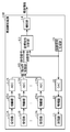
- FIG. 9 is a block diagram showing the configuration of the seating detection device 10C according to the fourth embodiment.
- the transmitter 11, the amplifier 16, the DAC 18, and the transmission signal generation unit 19 are deleted from the seating detection device 10 according to the first embodiment, and the door sensor 20 is used.
- Conditional learning model storage unit 70 is added, the acoustic characteristic analysis unit 13 is changed to the acoustic characteristic analysis unit 13C, and the detection unit 14 is changed to the detection unit 14C.
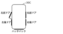
- FIG. 10 is a plan view schematically showing a vehicle 30C equipped with a seating detection device 10C.
- the seating detection device 10C is mounted on the vehicle 30C including the left front door, the right front door, the left rear door, the right rear door, and the hatchback, and is mounted on the vehicle 30C.
- Left front door, right front door, left rear door, right rear door, or the sound generated when the hatchback (hereinafter, simply referred to as "door") closes is used to detect the presence or absence of personnel or the presence or absence of seating. explain.
- the seating detection device according to the fourth embodiment is mounted on a structure having a function of generating sound in a space having a plurality of seats
- the seating detection device is not necessarily mounted on the structure of the vehicle 30C. It does not have to be limited, and the sound used to detect the presence / absence of personnel or the presence / absence of seating does not have to be limited to the sound generated when the door is closed.
- the seating detection device 10C will be described as being mounted on the vehicle 30C, but at least if the receiver 12 is mounted on the vehicle 30C, all the components of the seating detection device 10C are necessarily vehicles. It does not have to be mounted on the 30C.
- the door sensor 20 detects the open / closed state of each of the left front door, the right front door, the left rear door, the right rear door, and the hatchback.
- the acoustic characteristic analysis unit 13C calculates the time characteristic or frequency characteristic of the sound in the space inside the vehicle 30C, that is, the space having a plurality of seats, from the signal received by the receiver 12. More specifically, the acoustic characteristic analysis unit 13C inputs the door open / closed state detection result output from the door sensor 20 and the received signal output from the ADC 17, and the door open / closed state is detected from the door open / closed state detection result. Detects the closing event and acquires the received signals before and after the door closing event. Then, the acoustic characteristic analysis unit 13C calculates the time characteristic or the frequency characteristic of the sound in the space in the vehicle 30C from the acquired received signal.
- the door closing event changes from an open state to a closed state at least one of the left front door, the right front door, the left rear door, the right rear door, and the hatchback.
- the door closing event which refers to an event to be performed, occurs, for example, when the occupant of the vehicle 30C gets on or off the vehicle.
- the conditional learning model storage unit 70 stores a plurality of machine learning models (hereinafter, also simply referred to as “learning models”) trained under different conditions.
- Each of the plurality of learning models is trained in advance with the correct answer level attached to each of the time characteristics or frequency characteristics of the sound in the vehicle 30C output from the acoustic characteristic analysis unit 13C as teacher data.
- the conditions different from each other are at least the condition that the door closing event of the left front door occurs when all the other doors are closed, and the door closing event of the right front door when all the other doors are closed.
- the plurality of learning models stored in the conditional learning model storage unit 70 are trained using at least teacher data satisfying the condition that the door closing event of the left front door occurs while all the other doors are closed.
- FIG. 11 shows the correspondence between the teacher data used for training, the conditions satisfied by the teacher data, and the correct answer level attached to the teacher data for each of the plurality of learning models stored in the condition-based learning model storage unit 70. It is a schematic diagram which shows an example of a relationship.
- the detection unit 14C detects the presence / absence of personnel or the presence / absence of seating in the vehicle 30C based on the time characteristics or frequency characteristics of the sound in the space inside the vehicle 30C calculated by the acoustic characteristic analysis unit 13C, and outputs the detection result. do. More specifically, the detection unit 14C includes a discriminator 14C, and the discriminator 14C is used to analyze the time characteristics or frequency characteristics of the sound in the space in the vehicle 30C calculated by the acoustic characteristic analysis unit 13C, and the acoustic characteristic analysis.
- the presence / absence of personnel or the presence / absence of seating in the vehicle 30 output from the classifier 14C is acquired, and the presence / absence of personnel or the presence / absence of seating in the acquired vehicle 30 is obtained. Output.
- the condition is satisfied.
- a training model trained using teacher data satisfying the conditions corresponding to the input door closing event is acquired.
- the classifier 14C inputs the time characteristic or the frequency characteristic of the sound of the space in the input vehicle 30C into the acquired learning model, and the presence / absence of personnel or the presence / absence of seating in the vehicle 30 output from the learning model. Is acquired, and the presence / absence of personnel or the presence / absence of seating in the acquired vehicle 30 is output.
- the seating detection device 10C having the above configuration performs a second seating detection process for detecting seating in the vehicle 30C.
- FIG. 12 is a flowchart of the second seating detection process.
- the acoustic characteristic analysis unit 13C starts an attempt to detect the door closing event (step S110).
- step S110 when the acoustic characteristic analysis unit 13C detects a door closing event (step S110: No is repeated, then step S110: Yes), all the doors other than the door subject to the detected door closing event. Check if is closed (step S120).
- step S120 when all the doors other than the door targeted for the detected door closing event are closed (step S120: Yes), the acoustic characteristic analysis unit 13C receives signals before and after the detected door closing event. (Step S130).
- the acoustic characteristic analysis unit 13C calculates the time characteristics or frequency characteristics of the sound in the space inside the vehicle 30C from the acquired received signals (step S140).
- the detection unit 14C was trained using the teacher data satisfying the conditions corresponding to the door closing event detected by the acoustic characteristic analysis unit 13C.
- the learning model the presence / absence of personnel or the presence / absence of seating in the vehicle 30 is acquired (step S150).
- step S120 when at least one of the doors other than the door targeted for the detected door closing event is not closed (step S120: No), and when the process of step S150 is completed, the seating detection device 10C Ends the second seating detection process.
- the seating detection device 10C having the above configuration, it is possible to detect the presence / absence of personnel or the presence / absence of seating by using the sound generated when the door is closed.
- the seating detection device has been described above based on the first to third embodiments, but the present disclosure is not limited to these embodiments, and the purpose of the present disclosure is not limited to these embodiments. As long as it does not deviate from the above, various modifications that can be conceived by those skilled in the art are applied to these embodiments, and embodiments constructed by combining components in different embodiments are also within the scope of one or more embodiments of the present disclosure. May be included in.
- the seating detection device 10 has been described as being installed at a position in the overhead console 32 that is deviated from the center line extending in the traveling direction of the vehicle 30.
- the seating detection device 10 is located at a position where the ultrasonic waves transmitted from the transmitter 11 can be reflected by the seats and reach the receiver 12 with respect to at least one of the seats 31A to 31D. If this is the case, it is not necessarily limited to the example in which the vehicle 30 is installed at a position deviated from the center line extending in the traveling direction in the overhead console 32.
- the position of the seating detection device 10 is not necessarily limited, but the distance until the ultrasonic wave transmitted from the transmitter 11 is reflected by the seat 31A and reaches the receiver 12 (hereinafter, "first distance”). (Also also referred to as)), the distance until the ultrasonic wave transmitted from the transmitter 11 is reflected by the seat 31B and reaches the receiver 12 (hereinafter, also referred to as a “second distance”), and the transmission from the transmitter 11. The distance until the ultrasonic waves are reflected by the seat 31C and reach the receiver 12 (hereinafter, also referred to as "third distance”) and the ultrasonic waves transmitted from the transmitter 11 are reflected by the seat 31D.
- the seat in the vehicle is located at a position of line symmetry about the center line extending in the traveling direction of the vehicle. Therefore, in order to make the first distance, the second distance, the third distance, and the fourth distance different from each other in the vehicle 30, for example, among the transmitter 11 and the receiver 12. At least one is located at a position deviated from the center line extending in the traveling direction of the vehicle 30, and the transmitter 11 is not located at a position symmetrical with respect to the receiver 12 with the center line as the target axis. It is realized by.
- the difference calculation unit 22 uses the newly input impulse response as the first impulse response and the impulse response input immediately before the first impulse response as the second impulse response.
- the impulse response it has been described that the difference between the first impulse response and the second impulse response is calculated.
- the first impulse response and the second impulse response are ultrasonic impulse responses transmitted by the transmitter 11 at different timings from each other, they are not necessarily the newly input impulse response and the immediately preceding impulse response. It does not have to be limited to the example of the impulse response input to.
- the first impulse response and the second impulse response are, for example, the newly input impulse response as the first impulse response, and the impulse response in the unmanned vehicle 30 calculated in advance by the acoustic characteristic analysis unit 13. May be used as the second impulse response.
- the transmission signal generated by the transmission signal generation unit 19 has been described as being a signal composed of a sweep sine wave.
- the transmitted signal need not be limited to a signal consisting of a sweep sine wave.
- the transmission signal may be, for example, a signal composed of white noise, or may be, for example, a signal composed of band noise or a sine wave.
- the signaled period and the non-signaled period are not limited to 43 ms, and the signaled period and the non-signaled period may have different lengths from each other.
- the detection unit 14 is described as being configured to include the absolute value calculation unit 23.
- the difference calculation unit 22 calculates the calculated difference signal in the change position calculation unit 24, and the change position calculation unit 24 receives the difference signal from the difference calculation unit 22 based on the difference signal.
- the seating in the vehicle 30 is detected, and the detection information indicating the detection result is output.
- the change position calculation unit 24 detects that there is a seat, outputs the seating information indicating that there is a seat, and outputs the seating information indicating that there is a seat. When there is no difference between the above, it is detected that there is no seating, and the seating information indicating that there is no seating is output. Further, when a difference of a predetermined value or more occurs in the difference signal, the change position calculation unit 24 calculates the seating position from the position on the time axis in the difference signal in which the difference occurs and outputs it.
- the seating information to be performed includes information indicating the calculated seating position.
- the receiver 12 may be, for example, a digital MEMS (Micro Electro Mechanical System) microphone.
- the amplifier 15 and the ADC 17 are unnecessary.
- an example of a vehicle having a plurality of seats has been described as an example of a space having a plurality of seats, but the space having a plurality of seats is limited to the example of a vehicle having a plurality of seats. It is not necessary, and it may be a moving body other than a vehicle which is a passenger car.
- the seating detection device 10 can also be applied to, for example, seating detection in a multi-person vehicle, a bus, a train, an aircraft, or the like, which is a moving body other than a passenger car. For vehicles, buses, trains, aircraft, etc. with a large number of passengers, crew members are currently patrolling to confirm seating, etc., but by applying the seating detection device 10, the number of patrols by crew members, etc. will be reduced. It is also possible to reduce the risk of infectious diseases such as coronavirus.
- the space having a plurality of seats does not have to be limited to a moving body, and may be another place, for example, a room having seats such as a movie theater.
- the seating detection device 10C has been described as detecting the presence / absence of personnel or the presence / absence of seating by using the sound generated when the door of the vehicle 30C is closed.
- the sound used by the seating detection device 10C to detect the presence / absence of personnel or the presence / absence of seating is a sound generated inside or outside the vehicle 30C, it is not necessarily a sound generated when the door of the vehicle 30C is closed. It does not have to be limited to.
- the sound used by the seating detection device 10C to detect the presence / absence of a person or the presence / absence of seating may be the storage sound of the door mirror or the external noise of the vehicle 30C.
- the type of sound used by the seating detection device 10C to detect the presence / absence of personnel or the presence / absence of seating is not particularly limited, and may be, for example, an audible sound or an ultrasonic wave. good.
- One aspect of the present disclosure is not only the seating detection device according to the first to fourth embodiments, but also a seating detection method using a characteristic component included in the seating detection device as a step. good. Further, one aspect of the present disclosure may be a program for causing a device including a computer to execute each characteristic step included in the seating detection method. Also, one aspect of the present disclosure may be a computer-readable non-temporary recording medium on which such a program is recorded.
- the present disclosure can be widely used as a seating detection device or the like for detecting the presence or absence of personnel or the presence or absence of seating in a space having a plurality of seats.
Landscapes
- Engineering & Computer Science (AREA)
- Mechanical Engineering (AREA)
- Radar, Positioning & Navigation (AREA)
- Physics & Mathematics (AREA)
- Remote Sensing (AREA)
- Aviation & Aerospace Engineering (AREA)
- Transportation (AREA)
- Computer Networks & Wireless Communication (AREA)
- Acoustics & Sound (AREA)
- General Physics & Mathematics (AREA)
- Seats For Vehicles (AREA)
- Geophysics And Detection Of Objects (AREA)
- Measurement Of Velocity Or Position Using Acoustic Or Ultrasonic Waves (AREA)
Priority Applications (4)
| Application Number | Priority Date | Filing Date | Title |
|---|---|---|---|
| EP21827043.7A EP4169775B1 (en) | 2020-06-18 | 2021-06-04 | Seating detection device, seating detection method, and program |
| CN202180007613.6A CN114868036A (zh) | 2020-06-18 | 2021-06-04 | 就座检测装置、就座检测方法及程序 |
| JP2022531673A JPWO2021256303A1 (https=) | 2020-06-18 | 2021-06-04 | |
| US17/840,071 US12128843B2 (en) | 2020-06-18 | 2022-06-14 | Occupied seat detection device, occupied seat detection method, and non-transitory computer-readable recording medium |
Applications Claiming Priority (2)
| Application Number | Priority Date | Filing Date | Title |
|---|---|---|---|
| JP2020-105431 | 2020-06-18 | ||
| JP2020105431 | 2020-06-18 |
Related Child Applications (1)
| Application Number | Title | Priority Date | Filing Date |
|---|---|---|---|
| US17/840,071 Continuation US12128843B2 (en) | 2020-06-18 | 2022-06-14 | Occupied seat detection device, occupied seat detection method, and non-transitory computer-readable recording medium |
Publications (1)
| Publication Number | Publication Date |
|---|---|
| WO2021256303A1 true WO2021256303A1 (ja) | 2021-12-23 |
Family
ID=79267878
Family Applications (1)
| Application Number | Title | Priority Date | Filing Date |
|---|---|---|---|
| PCT/JP2021/021384 Ceased WO2021256303A1 (ja) | 2020-06-18 | 2021-06-04 | 着座検知装置、着座検知方法、及び、プログラム |
Country Status (5)
| Country | Link |
|---|---|
| US (1) | US12128843B2 (https=) |
| EP (1) | EP4169775B1 (https=) |
| JP (1) | JPWO2021256303A1 (https=) |
| CN (1) | CN114868036A (https=) |
| WO (1) | WO2021256303A1 (https=) |
Families Citing this family (2)
| Publication number | Priority date | Publication date | Assignee | Title |
|---|---|---|---|---|
| DE102022122348B4 (de) * | 2022-09-05 | 2024-07-25 | Bayerische Motoren Werke Aktiengesellschaft | Vorrichtung und Verfahren zur exakten Sitzbelegungserkennung |
| JPWO2024121957A1 (https=) * | 2022-12-07 | 2024-06-13 |
Citations (8)
| Publication number | Priority date | Publication date | Assignee | Title |
|---|---|---|---|---|
| JPH11151970A (ja) | 1997-09-09 | 1999-06-08 | Yazaki Corp | 車両乗員検知装置 |
| JP2000016233A (ja) | 1998-07-07 | 2000-01-18 | Matsushita Electric Ind Co Ltd | 座席用人体検出装置 |
| JP2006069454A (ja) | 2004-09-06 | 2006-03-16 | Matsushita Electric Ind Co Ltd | 車両用着座判定装置およびそのプログラム |
| JP2006090730A (ja) * | 2004-09-21 | 2006-04-06 | Secom Co Ltd | センシング装置 |
| JP2012190329A (ja) * | 2011-03-11 | 2012-10-04 | Sumitomo Electric Ind Ltd | 配置場所評価装置、侵入検知システム、配置場所評価方法および配置場所評価プログラム |
| WO2015074685A1 (en) * | 2013-11-20 | 2015-05-28 | Fundació Barcelona Media | Method and system for intrusion and fire detection |
| JP2015179524A (ja) * | 2010-06-29 | 2015-10-08 | クゥアルコム・インコーポレイテッドQualcomm Incorporated | 持続波超音波信号を使用したタッチレス感知およびジェスチャー認識 |
| JP2019138671A (ja) | 2018-02-06 | 2019-08-22 | ミツミ電機株式会社 | カメラおよび乗員検知システム |
Family Cites Families (22)
| Publication number | Priority date | Publication date | Assignee | Title |
|---|---|---|---|---|
| JPH01237483A (ja) * | 1988-03-18 | 1989-09-21 | Matsushita Electric Ind Co Ltd | 超音波式侵入者検知器 |
| GB9206360D0 (en) * | 1992-03-24 | 1992-05-06 | Rover Group | A device for and a method of surveillance of a space |
| US6397136B1 (en) * | 1997-02-06 | 2002-05-28 | Automotive Technologies International Inc. | System for determining the occupancy state of a seat in a vehicle |
| JPH0689782A (ja) * | 1992-09-07 | 1994-03-29 | Hitachi Cable Ltd | 照明自動点滅装置 |
| JPH0920193A (ja) * | 1995-07-07 | 1997-01-21 | Nippon Seiko Kk | 車両内乗員位置検出装置 |
| KR100272906B1 (ko) * | 1995-09-08 | 2000-11-15 | 제발트 알로이스 | 부분 공간의 탐지 및 감시 방법 |
| US6029105A (en) | 1996-09-09 | 2000-02-22 | Trw Automotive Electronics & Components Gmbh & Co. Kg | Method and apparatus for detecting and monitoring a partial space |
| JP3417274B2 (ja) * | 1997-10-27 | 2003-06-16 | 松下電工株式会社 | 人体検出装置 |
| US6327221B1 (en) * | 1999-09-20 | 2001-12-04 | Honeywell International Inc. | Steered beam ultrasonic sensor for object location and classification |
| JP2001116556A (ja) * | 1999-10-15 | 2001-04-27 | Matsushita Electric Ind Co Ltd | 緊急通報システム |
| EP1482763A3 (en) * | 2003-05-26 | 2008-08-13 | Matsushita Electric Industrial Co., Ltd. | Sound field measurement device |
| JP2005030838A (ja) * | 2003-07-09 | 2005-02-03 | Sumitomo Osaka Cement Co Ltd | 監視装置及び監視方法 |
| JP4595666B2 (ja) * | 2005-05-13 | 2010-12-08 | パナソニック電工株式会社 | 車両用安全システム |
| JP4955381B2 (ja) * | 2006-12-25 | 2012-06-20 | 関西電力株式会社 | 超音波画像化方法及び超音波画像化装置 |
| KR100947117B1 (ko) * | 2007-12-13 | 2010-03-10 | 한국전자통신연구원 | 이동체의 위치 추적 시스템 및 방법 |
| JP5370132B2 (ja) * | 2009-12-22 | 2013-12-18 | 株式会社デンソー | 障害物検出装置 |
| US9157898B1 (en) * | 2010-03-22 | 2015-10-13 | Lutron Electronics Co., Inc. | Ultrasonic receiving circuit |
| JP2012122806A (ja) * | 2010-12-07 | 2012-06-28 | Panasonic Corp | 移動体検出装置 |
| JP5292422B2 (ja) * | 2011-02-24 | 2013-09-18 | 株式会社東芝 | 車載用頭部位置検出装置、車載用表示装置及び運転支援装置 |
| JP6003181B2 (ja) * | 2012-04-20 | 2016-10-05 | マツダ株式会社 | 自動車用侵入検知装置 |
| KR102567188B1 (ko) * | 2017-12-20 | 2023-08-16 | 현대자동차주식회사 | 차량 및 그 제어 방법 |
| JP6716621B2 (ja) * | 2018-03-07 | 2020-07-01 | セコム株式会社 | 物体判定装置及びセンサ装置 |
-
2021
- 2021-06-04 WO PCT/JP2021/021384 patent/WO2021256303A1/ja not_active Ceased
- 2021-06-04 JP JP2022531673A patent/JPWO2021256303A1/ja active Pending
- 2021-06-04 EP EP21827043.7A patent/EP4169775B1/en active Active
- 2021-06-04 CN CN202180007613.6A patent/CN114868036A/zh active Pending
-
2022
- 2022-06-14 US US17/840,071 patent/US12128843B2/en active Active
Patent Citations (8)
| Publication number | Priority date | Publication date | Assignee | Title |
|---|---|---|---|---|
| JPH11151970A (ja) | 1997-09-09 | 1999-06-08 | Yazaki Corp | 車両乗員検知装置 |
| JP2000016233A (ja) | 1998-07-07 | 2000-01-18 | Matsushita Electric Ind Co Ltd | 座席用人体検出装置 |
| JP2006069454A (ja) | 2004-09-06 | 2006-03-16 | Matsushita Electric Ind Co Ltd | 車両用着座判定装置およびそのプログラム |
| JP2006090730A (ja) * | 2004-09-21 | 2006-04-06 | Secom Co Ltd | センシング装置 |
| JP2015179524A (ja) * | 2010-06-29 | 2015-10-08 | クゥアルコム・インコーポレイテッドQualcomm Incorporated | 持続波超音波信号を使用したタッチレス感知およびジェスチャー認識 |
| JP2012190329A (ja) * | 2011-03-11 | 2012-10-04 | Sumitomo Electric Ind Ltd | 配置場所評価装置、侵入検知システム、配置場所評価方法および配置場所評価プログラム |
| WO2015074685A1 (en) * | 2013-11-20 | 2015-05-28 | Fundació Barcelona Media | Method and system for intrusion and fire detection |
| JP2019138671A (ja) | 2018-02-06 | 2019-08-22 | ミツミ電機株式会社 | カメラおよび乗員検知システム |
Non-Patent Citations (1)
| Title |
|---|
| See also references of EP4169775A4 |
Also Published As
| Publication number | Publication date |
|---|---|
| US12128843B2 (en) | 2024-10-29 |
| EP4169775B1 (en) | 2026-04-29 |
| CN114868036A (zh) | 2022-08-05 |
| JPWO2021256303A1 (https=) | 2021-12-23 |
| US20220314917A1 (en) | 2022-10-06 |
| EP4169775A1 (en) | 2023-04-26 |
| EP4169775A4 (en) | 2023-11-29 |
Similar Documents
| Publication | Publication Date | Title |
|---|---|---|
| CN105835804B (zh) | 用于监测车辆后部乘客就坐区域的方法和设备 | |
| JP7510346B2 (ja) | 車両内生理学的感知のための装置、システムおよび方法 | |
| US9240176B2 (en) | Active noise control system and method | |
| US10252640B2 (en) | Seatbelt and child seat anchor based occupancy detection system | |
| US8284041B2 (en) | Method and apparatus for in-vehicle presence detection and driver alerting | |
| US9743213B2 (en) | Enhanced auditory experience in shared acoustic space | |
| US9747917B2 (en) | Position directed acoustic array and beamforming methods | |
| EP3886090B1 (en) | In-cabin acoustic-based passenger occupancy and situation state assessment | |
| EP3042795A3 (en) | System and method to detect an unattended occupant in a vehicle and take safety countermeasures | |
| CN109070836A (zh) | 基于座椅安全带及儿童座椅锚固件的占用检测系统 | |
| CN107113498A (zh) | 声音处理装置 | |
| WO2021256303A1 (ja) | 着座検知装置、着座検知方法、及び、プログラム | |
| EP3618465B1 (en) | Vehicle communication system and method of operating vehicle communication systems | |
| US9390713B2 (en) | Systems and methods for filtering sound in a defined space | |
| US12228641B2 (en) | Ultrasonic breathing sensor and sensing method for vehicle occupant monitoring | |
| CN116420177A (zh) | 具有存在识别系统的车辆和用于针对被遗忘在车辆内的生命体发出警告的方法 | |
| US10422874B2 (en) | Method and system for spatial modeling of an interior of a vehicle | |
| US12472939B2 (en) | Agent apparatus | |
| KR20220165931A (ko) | 차량용 능동소음제어장치 | |
| KR102317494B1 (ko) | 차량 하차 확인 장치, 이를 이용한 차량 하차 확인 시스템 및 방법 | |
| JPWO2021256303A5 (https=) | ||
| WO2019040043A1 (en) | OCCUPANCY DETECTION SYSTEM BASED ON SEAT BELT AND CHILD SEAT ANCHORAGE | |
| US20250259616A1 (en) | Method for diagnosing failure of active noise cancelling system for mobile vehicles | |
| CN118436376A (zh) | 用于监测车辆乘员的方法及声换能器的控制器 | |
| JP2023180483A (ja) | マイクシステム |
Legal Events
| Date | Code | Title | Description |
|---|---|---|---|
| 121 | Ep: the epo has been informed by wipo that ep was designated in this application |
Ref document number: 21827043 Country of ref document: EP Kind code of ref document: A1 |
|
| ENP | Entry into the national phase |
Ref document number: 2022531673 Country of ref document: JP Kind code of ref document: A |
|
| NENP | Non-entry into the national phase |
Ref country code: DE |
|
| ENP | Entry into the national phase |
Ref document number: 2021827043 Country of ref document: EP Effective date: 20230118 |