WO2021256274A1 - メタンガス分解方法、メタンガス分解装置 - Google Patents
メタンガス分解方法、メタンガス分解装置 Download PDFInfo
- Publication number
- WO2021256274A1 WO2021256274A1 PCT/JP2021/021148 JP2021021148W WO2021256274A1 WO 2021256274 A1 WO2021256274 A1 WO 2021256274A1 JP 2021021148 W JP2021021148 W JP 2021021148W WO 2021256274 A1 WO2021256274 A1 WO 2021256274A1
- Authority
- WO
- WIPO (PCT)
- Prior art keywords
- gas
- methane
- treated
- tube
- methane gas
- Prior art date
- Legal status (The legal status is an assumption and is not a legal conclusion. Google has not performed a legal analysis and makes no representation as to the accuracy of the status listed.)
- Ceased
Links
Images









Classifications
-
- B—PERFORMING OPERATIONS; TRANSPORTING
- B01—PHYSICAL OR CHEMICAL PROCESSES OR APPARATUS IN GENERAL
- B01D—SEPARATION
- B01D53/00—Separation of gases or vapours; Recovering vapours of volatile solvents from gases; Chemical or biological purification of waste gases, e.g. engine exhaust gases, smoke, fumes, flue gases, aerosols
- B01D53/34—Chemical or biological purification of waste gases
- B01D53/46—Removing components of defined structure
- B01D53/72—Organic compounds not provided for in groups B01D53/48 - B01D53/70, e.g. hydrocarbons
-
- B—PERFORMING OPERATIONS; TRANSPORTING
- B01—PHYSICAL OR CHEMICAL PROCESSES OR APPARATUS IN GENERAL
- B01J—CHEMICAL OR PHYSICAL PROCESSES, e.g. CATALYSIS OR COLLOID CHEMISTRY; THEIR RELEVANT APPARATUS
- B01J19/00—Chemical, physical or physico-chemical processes in general; Their relevant apparatus
- B01J19/08—Processes employing the direct application of electric or wave energy, or particle radiation; Apparatus therefor
-
- H—ELECTRICITY
- H05—ELECTRIC TECHNIQUES NOT OTHERWISE PROVIDED FOR
- H05H—PLASMA TECHNIQUE; PRODUCTION OF ACCELERATED ELECTRICALLY-CHARGED PARTICLES OR OF NEUTRONS; PRODUCTION OR ACCELERATION OF NEUTRAL MOLECULAR OR ATOMIC BEAMS
- H05H1/00—Generating plasma; Handling plasma
- H05H1/24—Generating plasma
-
- Y—GENERAL TAGGING OF NEW TECHNOLOGICAL DEVELOPMENTS; GENERAL TAGGING OF CROSS-SECTIONAL TECHNOLOGIES SPANNING OVER SEVERAL SECTIONS OF THE IPC; TECHNICAL SUBJECTS COVERED BY FORMER USPC CROSS-REFERENCE ART COLLECTIONS [XRACs] AND DIGESTS
- Y02—TECHNOLOGIES OR APPLICATIONS FOR MITIGATION OR ADAPTATION AGAINST CLIMATE CHANGE
- Y02C—CAPTURE, STORAGE, SEQUESTRATION OR DISPOSAL OF GREENHOUSE GASES [GHG]
- Y02C20/00—Capture or disposal of greenhouse gases
- Y02C20/20—Capture or disposal of greenhouse gases of methane
Definitions
- the present invention relates to a methane gas decomposition method and a methane gas decomposition apparatus.
- FIG. 10 is a drawing schematically showing the configuration of the methane removal system.
- the methane removal system 100 is a system that decomposes methane contained in the gas to be treated, and includes a gas pipe 102 to be treated, a catalyst 104 for removing methane oxidation, a plasma generation means 105, and a control means 106.
- the processed gas pipe 102 is set inside the processed gas passage 102a for discharging the processed gas Eg from the processed gas discharge source 101.
- the catalyst 104 for removing methane oxidation is housed in a layer in a catalyst accommodating portion 104a set in the gas passage 102a to be treated, and is arranged to remove the gas Eg to be treated flowing in the gas passage 102a to be treated. ing.
- the plasma generating means 105 includes an external electrode 108a, an internal electrode 108b, and a power supply source 107.
- the external electrode 108a is arranged on the outer peripheral surface of the gas pipe 102 to be treated so as to surround the catalyst accommodating portion 104a, and has a tubular shape.
- the internal electrode 108b is arranged at a position corresponding to the catalyst accommodating portion 104a in the gas passage 102a to be treated.
- One terminal of the power supply source 107 is electrically connected to the internal electrode 108b.
- the other terminal of the power supply source 107 and the external electrode 108a are grounded.
- the plasma generation means 105 supplies electric power to the internal electrode 108b by the electric power supply source 107 to generate atmospheric pressure plasma at a place where the catalyst 104 for removing methane oxidation accommodated in the catalyst accommodating portion 104a exists.
- the gas to be treated Eg flowing in the gas passage 102a to be treated is turned into plasma in the catalyst accommodating portion 104a, and the generated plasma activates the catalyst 104 for removing methane oxidation.
- the methane contained in the gas to be treated Eg is decomposed into carbon dioxide by the synergistic effect of the action of the activated catalyst for removing methane oxidation 104 and the action of the generated plasma.
- the largest amount of methane emitted is from livestock, etc. as flatulence and burp.
- the amount of methane emitted from one cow is said to be about 300 liters a day.
- the atmospheric concentration of methane emitted from livestock such as cattle raised in the barn is about 20 ppm.
- Patent Document 1 describes that methane could be decomposed by passing a gas to be treated having a methane concentration of 3000 ppm. However, it cannot be said that the technology for almost completely decomposing low-concentration methane such as several hundred ppm or less has been sufficiently established at this time.
- an object of the present invention is to provide a technique capable of decomposing methane by a simple method even for a gas to be treated containing methane at a low concentration of several hundred ppm or less.
- the temperature of the gas to be treated is raised by passing the gas to be treated, which is a mixture of methane gas in air, in the atmospheric pressure plasma space formed by the dielectric barrier discharge. It is characterized by decomposing methane.
- the gas to be treated may be allowed to flow into the atmospheric pressure plasma space in a state of being heated to 200 ° C. or higher.
- the decomposition rate of methane is improved by passing the gas to be treated containing methane gas through the atmospheric pressure plasma space at a high temperature of 200 ° C. or higher. That is, according to the above method, the decomposition rate of methane gas can be increased.
- the gas to be treated may be passed through the atmospheric pressure plasma space in a humidified state.
- the decomposition rate of methane is improved by passing the gas to be treated including methane gas through the atmospheric pressure plasma space in a humidified state. That is, according to the above method, the decomposition rate of methane gas can be increased.
- the methane gas decomposition apparatus is A tube body including a tube wall made of a dielectric and a tube body A pair of electrodes arranged across the tube wall, A power supply that applies a high frequency voltage to the pair of electrodes, A gas inlet for introducing a gas to be treated, which is a mixture of methane gas in air inside the tube, and a gas inlet.
- a gas discharge port that discharges the gas to be processed that has passed through the atmospheric pressure plasma space formed inside the tube body by applying the high frequency voltage to the pair of electrodes to the outside of the tube body. It is characterized by being equipped with.
- the methane gas decomposition device in the space inside the tube through which the gas to be processed flows, the direction orthogonal to the tube axis direction of the tube and the direction from the tube wall toward the axis (for convenience, "diameter" An atmospheric pressure plasma space is formed over almost the entire area of "direction"). Therefore, since almost all of the introduced gas to be treated passes through the atmospheric pressure plasma space, the methane contained in the gas to be treated is efficiently decomposed.
- the pair of electrodes includes a first electrode formed on the outer surface of the tube wall and a second electrode formed inside the tube body by extending along the tube axis direction of the tube body. It may be configured to include.
- the pair of electrodes includes a first electrode formed on a part of the outer surface of the tube wall and the tube wall having a position facing the first electrode via the inside of the tube body. It may be configured to include a second electrode formed on a part of the outer surface.
- the pair of electrodes has a first electrode formed on a part of the outer surface of the tube wall and the tube wall at a position separated from the first electrode in the tube axis direction of the tube body. It may be configured to include a second electrode formed on a part of the outer surface of the above.
- the tube wall of the tube body located on the outside of the end portion of the atmospheric pressure plasma space formed inside the tube body on the gas discharge port side in the tube axis direction of the tube body is 230. It is preferably °C or higher.
- the temperature of the gas to be treated flowing in the atmospheric pressure plasma space can be set to 200 ° C. or higher, and the decomposition rate of methane can be increased.
- the temperature of the tube wall can be controlled, for example, by the electric power applied to the electrodes from the power source.
- another heater may be provided.
- methane can be decomposed by a simple method even for a gas to be treated containing methane at a low concentration of several hundred ppm or less.
- FIG. 3 is a cross-sectional view taken along the line A1-A1 in FIG. 1A. It is a top view schematically showing another configuration of 1st Embodiment of a methane gas decomposition apparatus.
- FIG. 2 is a cross-sectional view taken along the line A1-A1 in FIG. 2A. It is sectional drawing which shows typically another structure of 1st Embodiment of a methane gas decomposition apparatus. It is sectional drawing which shows typically another structure of 1st Embodiment of a methane gas decomposition apparatus.
- FIG. 3 is a cross-sectional view taken along the line A1-A1 in FIG. 3A. It is a top view schematically showing another configuration of the 2nd Embodiment of a methane gas decomposition apparatus.
- FIG. 3 is a cross-sectional view taken along the line A1-A1 in FIG. 4A. It is a top view which shows typically the structure of the 3rd Embodiment of a methane gas decomposition apparatus.
- FIG. 3 is a cross-sectional view taken along the line A1-A1 in FIG. 4A.
- FIG. 5 is a cross-sectional view taken along the line A1-A1 in FIG. 5A. It is sectional drawing which shows typically another structure of the 3rd Embodiment of a methane gas decomposition apparatus. It is a top view which shows typically the structure of the 4th Embodiment of a methane gas decomposition apparatus.
- 6 is a cross-sectional view taken along the line A1-A1 in FIG. 6A.
- FIG. 6 is a cross-sectional view taken along the line A2-A2 in FIG. 6A. It is a top view schematically showing another configuration of the 4th Embodiment of a methane gas decomposition apparatus. It is a top view which shows typically the method of the cooling process in an Example.
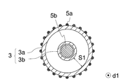
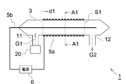
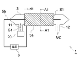
- FIG. 1A and 1B are drawings schematically showing the configuration of the first embodiment of the methane gas decomposition apparatus.
- FIG. 1B is a sectional view taken along line A1-A1 in FIG. 1A.
- the methane gas decomposition device 1 includes a tube body 3 and a pair of electrodes (5a, 5b).
- the tubular body 3 exhibits a double tubular structure. More specifically, as shown in FIG. 1B, the tube body 3 has a cylindrical shape and is arranged coaxially with the outer tube 3a located on the outside and the outer tube 3a inside the outer tube 3a. It has an inner tube 3b having a cylindrical shape having an inner diameter smaller than that of 3a.
- One electrode 5a (corresponding to the "first electrode”) is arranged on the outer wall of the outer tube 3a.
- the electrode 5a has a mesh shape.
- a rod-shaped electrode 5b (corresponding to the "second electrode") extending along the tube axial direction d1 of the tube body 3 is inserted inside the inner tube 3b.
- a discharge space S1 having a ring shape (here, an annular shape) when viewed from the pipe axis direction d1 is formed between the outer tube 3a and the inner tube 3b.
- the outer tube 3a and the inner tube 3b are made of a dielectric material such as quartz glass or ceramics.
- the electrodes (5a, 5b) are made of a metal material such as stainless steel, aluminum, copper, tungsten, or nickel.
- the pipe body 3 has two openings, each of which corresponds to the gas introduction port 11 and the gas discharge port 12.
- the gas introduction port 11 is an opening for introducing the treated gas G1 supplied from the gas supply source 20 in which methane gas is mixed with air into the inside of the pipe body 3.
- the gas supply source 20 is a mechanism for sending the gas to be treated G1 in the space requiring treatment of the atmosphere containing methane gas to the methane gas decomposition device 1, and is composed of, for example, a blower or a duct.
- the gas introduction port 11 is provided as an opening at a part of the outer pipe 3a, and is connected to the discharge space S1 located outside the inner pipe 3b. That is, the gas to be processed G1 supplied from the gas supply source 20 flows into the discharge space S1 through the gas introduction port 11.
- the gas discharge port 12 is arranged at a position separated from the gas introduction port 11 with respect to the pipe axial direction d1.
- the gas discharge port 12 is arranged at a position separated from the region where the electrode 5a is formed with respect to the pipe axis direction d1 with respect to the gas introduction port 11.
- the gas discharge port 12 is provided as an opening at a part of the outer pipe 3a, and is connected to the discharge space S1 located outside the inner pipe 3b.
- the methane gas decomposition device 1 includes a power source 6.
- the power supply 6 is connected to the electrodes 5a and 5b, and has a configuration in which a predetermined voltage is applied between both electrodes (5a, 5b).
- the applied voltage and frequency supplied from the power supply 6 are within a range in which a dielectric barrier discharge can be caused in the tube 3 by applying a voltage between the electrodes (5a, 5b). Just do it.
- the applied voltage supplied from the power supply 6 is preferably in the range of 3 kVpp or more and 50 kVpp or less.
- the frequency of the applied voltage supplied from the power supply 6 is preferably in the range of 1 kHz or more and 1000 kHz or less, and more preferably in the range of 1 kHz or more and 150 kHz or less.
- the reason why the upper limit is preferably 150 kHz is that the frequency detected by the noise terminal voltage in the EMC standard is 150 kHz or more. In this way, a high frequency voltage is applied between both electrodes (5a, 5b) from the power supply 6.
- the electrode 5a has a ground voltage and the electrode 5b has a high voltage. This reduces the risk of electric shock due to the high voltage of the electrodes exposed to the outside.
- a dielectric barrier discharge occurs in the tube body 3. That is, a dielectric barrier discharge is generated with respect to the gas to be treated G1 flowing in the discharge space S1 to generate plasma. That is, the discharge space S1 forms the atmospheric pressure plasma space.
- Oxygen contained in the gas to be treated G1 passes through the atmospheric pressure plasma space to show the reaction of the following equation (1).
- AP means that energy from atmospheric pressure plasma is applied.
- a part of the oxygen atom O generated by the formula (1) reacts with the oxygen molecule contained in the gas to be treated G1 to generate ozone (O 3) by the following formula (2).
- M in the formula (2) indicates the third body of the reaction (the same applies hereinafter).
- Methane contained in the gas to be treated G1 reacts with O (3 P) in the O atom and is converted into a methyl radical (CH 3 ) by the following equation (3). Further, the water vapor (H 2 O) contained in the gas to be treated G1 is decomposed by plasma to generate hydroxyl radical (OH) by the following equation (4). Further, the methane contained in the gas to be treated G1 also reacts with the hydroxyl radical (OH) as shown in the following equation (5). As the hydroxyl radical used in the reaction of the formula (5), the hydroxyl radical generated by the formula (4) is more dominant, but a part of the hydroxyl radical generated by the formula (3) is also included. CH 4 + O ( 3 P) ⁇ CH 3 + OH .... (3) H 2 O + AP ⁇ H + OH ...... (4) CH 4 + OH ⁇ CH 3 + H 2 O .... (5)
- the methyl radical (CH 3 ) obtained by the decomposition is further decomposed into more stable carbon monoxide (CO) and carbon dioxide (CO 2) through various reactions.
- the gas to be treated G1 flows through the discharge space S1 (atmospheric pressure plasma space), it is converted into the treated gas G2 in which the concentration of methane contained in the gas to be treated G1 is reduced. After this treatment, the gas G2 is discharged from the gas discharge port 12. This result will be described later with reference to Examples.
- the electrode 5a arranged on the tube wall of the outer tube 3a is not limited to the mesh shape.
- the electrode 5a may have a block shape arranged so as to cover the tube wall of the outer tube 3a in the circumferential direction.
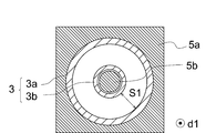
- 2A and 2B are drawings schematically showing the configuration of the methane gas decomposition apparatus of this other aspect according to FIGS. 1A and 1B, and FIG. 2B corresponds to the cross-sectional view taken along the line A1-A1 in FIG. 2A. do.
- the electrode 5a has a block shape having a cylindrical opening in the center, and the tubular body 3 is inserted into the opening.
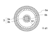
- the electrode 5a may have a curved side surface and may be configured to cover the outer wall of the outer tube 3a of the tubular body 3 in the circumferential direction (see FIG. 2C).
- the electrode 5a does not necessarily have to completely cover the tube wall of the outer tube 3a in the circumferential direction, and may be configured not to cover a part of the tube wall of the outer tube 3a, for example, as shown in FIG. 2D. No.
- the electrode 5a may have a configuration in which a mesh shape and a block shape are combined.
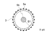
- FIG. 3A and 3B are drawings schematically showing the configuration of the second embodiment of the methane gas decomposition apparatus.
- FIG. 3B is a sectional view taken along line A1-A1 in FIG. 3A.
- the tube body 3 is composed of a single tube body.
- the electrode 5a is arranged on the outer wall of the tube body 3, and the electrode 5b is arranged so as to extend along the tube axis direction d1 of the tube body 3 at a position inside the tube body 3.
- the discharge space S1 is formed inside the tube body 3.
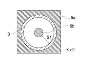
- the electrode 5a arranged on the outer wall of the tube 3 is not limited to the mesh shape, and for example, as shown in FIGS. 4A and 4B, the electrode 5a covers the outer wall of the tube 3 in the circumferential direction. It may have a block shape arranged in the above.
- 4A and 4B are drawings schematically showing the configuration of the methane gas decomposition apparatus of this other aspect according to FIGS. 3A and 3B, and FIG. 4B corresponds to the cross-sectional view taken along the line A1-A1 in FIG. 4A. do.
- the electrode 5a may have a curved surface shape and may be configured to cover the outer wall of the tube 3 in the circumferential direction, or may be a part of the outer wall of the tube 3. It may be a configuration that does not cover.
- FIG. 5A and 5B are drawings schematically showing the configuration of the third embodiment of the methane gas decomposition apparatus.
- FIG. 5B is a sectional view taken along line A1-A1 in FIG. 5A.
- the tube body 3 is composed of a single tube body. Further, in the present embodiment, the tube body 3 has a rectangular tubular shape having a pair of flat surfaces (7a, 7b) facing each other when viewed from the tube axis direction d1 (see FIG. 5B).
- both of the pair of electrodes (5a, 5b) are arranged on the outer wall of the tube body 3.
- One electrode 5a is arranged on the flat surface 7a, and the other electrode 5b is arranged on the flat surface 7b. That is, the mutual electrodes (5a, 5b) are separated by the tube body 3.
- the electrodes (5a, 5b) may have a mesh shape or a film shape.
- the pipe body 3 may have a circular shape when viewed from the pipe axis direction d1.
- both electrodes (5a, 5b) extend in the tube axial direction d1 while exhibiting a shape along the curved surface of the outer wall of the tube 3, and mutually pass through the tube 3. Separated.
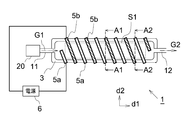
- FIG. 6A to 6C are drawings schematically showing the configuration of the fourth embodiment of the methane gas decomposition apparatus.
- 6B is a sectional view taken along line A1-A1 in FIG. 6A
- FIG. 6C is a sectional view taken along line A2-A2 in FIG. 6A.
- the tube body 3 is composed of a single tube body.
- the electrodes 5a and 5b are respectively arranged on the outer wall of the tube body 3, and both are arranged alternately in a spiral shape when viewed in a direction orthogonal to the tube axis direction d1. ing. That is, as shown in FIGS. 6A to 6C, the place where the electrode arranged on the pipe wall on the + d2 side of the pipe body 3 becomes the electrode 5a and the place where the electrode 5b becomes, depending on the position related to the pipe axis direction d1. Is a mode in which and is changed. The same applies to the electrodes arranged on the tube wall on the ⁇ d2 side of the tube body 3.
- the electrodes 5a and 5b are arranged in a state of being formed along the surface of the tube wall of the tube body 3 and in a state of being separated from each other along the tube axial direction d1. It does not matter if it is done. In this case, the electrodes 5a and 5b are arranged so as to be separated from each other along the tube axis direction d1.
- the space sandwiched between the electrodes 5a and 5b in the tube axial direction d1 forms the atmospheric pressure plasma space inside the tube body 3. That is, the atmospheric pressure plasma space is discretely arranged along the tube axis direction d1.
- the gas to be treated G1 flows through each atmospheric pressure plasma space, it is decomposed in the same manner as in the first embodiment, and the gas is discharged as the treated gas G2 having a reduced methane content concentration. It is discharged from the outlet 12.
- An atmospheric pressure plasma space was formed inside the body 3. Specifically, a high frequency voltage having an applied voltage of 15 to 18 kVpp, a frequency of 40 to 50 kHz, and a pulse width of 1.8 ⁇ sec was applied between both electrodes (5a, 5b).
- the treated gas G2 discharged from the gas discharge port 12 is introduced into a sampling bag (manufactured by GL Sciences), and FTIR (Fourier transform infrared spectroscopy) is applied to the treated gas G2 contained in the sampling bag. Component analysis was performed using.
- thermocouple a value measured by a thermocouple was adopted as the temperature of the outer wall of the pipe body 3 outside the formation portion of the electrode 5a at the position closest to the gas discharge port 12 in the pipe axis direction d1.
- cooling water W1 having a water temperature of 15 ° C. was passed through the inner pipe 3b in order to cool the gas to be treated G1 (see FIG. 8A).
- Example 1 in which the cooling, heating, and humidifying treatments were not performed, when the mutual results were compared, the case of Example 1 in which the flow rate of the gas to be treated was 3 L / min, which was the smallest. It was confirmed that almost 100% of the methane contained in the gas to be treated G1 could be decomposed.
- the description of "almost 100%” here means that it is below the detection limit and does not consider the order of 0.01 ppm or less (10 ppb or less).
- Example 4 methane contained in the gas to be treated G1 could be decomposed by about 20%. That is, from the results of Examples 1 to 4, it was confirmed that methane can be decomposed even when the concentration of methane contained in the gas to be treated G1 is as low as 100 ppm.
- Example 3 when Example 3 and Example 5 in which the flow rates of the gas to be treated G1 are both 10 L / min are compared, Example 5 in which the cooling treatment for the gas to be treated G1 is subjected to the cooling treatment is compared with Example 3. It was confirmed that the decomposition performance of methane was significantly reduced. Similarly, comparing Example 4 and Example 6 in which the flow rates of the gas to be treated G1 are both 20 L / min, Example 6 in which the cooling treatment for the gas to be treated G1 is cooled is methane as compared with Example 4. It was confirmed that the decomposition performance was significantly reduced.
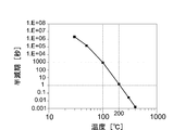
- FIG. 9 is a graph showing the relationship between the thermal decomposition rate (half-life) of ozone and the temperature. According to FIG. 9, it can be seen that the half-life of ozone is about 1000 seconds at 100 ° C. and the half-life of ozone is about 1 second at 200 ° C. That is, it can be seen that when ozone is heated to 200 ° C. or higher, ozone is decomposed within 1 second to generate O (3 P).
- the temperature T1 of the outer wall of the tube 3 outside the formation portion of the electrode 5a at the position closest to the gas discharge port 12 is less than 200 ° C. In view of this (see Table 2), it is probable that the temperature of the treated gas G2 did not exceed 200 ° C., and ozone that was not thermally decomposed remained in the treated gas G2. On the other hand, in Examples 3 and 4, in view of the fact that the temperature T1 of the outer wall of the tube 3 outside the formation portion of the electrode 5a at the position closest to the gas discharge port 12 is 230 ° C. or higher (see Table 2).
- the temperature T1 of the portion of the tube 3 corresponding to the outside of the end position on the gas discharge port 12 side of the atmospheric pressure plasma space is 230 ° C. or higher, the temperature is within the atmospheric pressure plasma space. It is considered that the temperature of the gas to be processed G1 passing through the above can be set to 200 ° C. or higher.
- Example 7 in which the heat treatment to the gas to be treated G1 is heat-treated is higher than that in Example 2. Furthermore, it was confirmed that the decomposition performance of methane was improved. More specifically, in the case of Example 2, 24.0 ppm of methane remained in the treated gas G2, whereas according to Example 7 in which the heat-treated gas G1 was heat-treated. The concentration of methane contained in the treated gas G2 was below the detection limit.
- Example 3 Compared Example 3 and Example 8 in which the flow rates of the gas to be treated G1 are both 10 L / min, Example 8 in which the heat treatment to the gas to be treated G1 is heat-treated is more methane than Example 3. It was confirmed that the disassembly performance was improved. Similarly, comparing Example 4 and Example 9 in which the flow rates of the gas to be treated G1 are both 20 L / min, Example 9 in which the heat treatment to the gas to be treated G1 is heat-treated is more methane than Example 4. It was confirmed that the disassembly performance was improved.
- the temperature of the gas to be treated G1 becomes high at the time of passing through the atmospheric pressure plasma space (in the discharge space S1), and as a result, the decomposition of ozone described in the above equation (6) is performed. It is considered that the rate of the reaction and the decomposition reaction of methane described in the above equation (3) was accelerated, and the decomposition rate of methane was improved.
- Example 10 in which the gas to be treated G1 is humidified is higher than that in Example 3. Furthermore, it was confirmed that the decomposition performance of methane was improved. More specifically, in the case of Example 3, 52.9 ppm of methane remained in the treated gas G2, whereas according to Example 10 in which the treated gas G1 was humidified. The concentration of methane contained in the treated gas G2 was 31.9 ppm.
- Methane gas decomposition device 3 Tube body 3a: Outer tube 3b: Inner tube 5a: Electrode (first electrode) 5b: Electrode (second electrode) 6: Power supply 7a: Flat surface 7b: Flat surface 11: Gas inlet 12: Gas discharge port 20: Gas supply source 30: Electric furnace 31: Container 32: Introduction pipe 33: Outlet pipe 100: Methane removal system 101: Processed Gas discharge source 102: Gas pipe 102a to be treated: Gas path 104 to be treated: Catalyst 104a for removing methane oxidation: Catalyst accommodating portion 105: Plasma generating means 106: Control means 107: Power supply source 108a: External electrode 108b: Internal electrode G1 : Processed gas G2: Treated gas S1: Discharge space W1: Cooling water W2: Water d1: Pipe axis direction
Landscapes
- Chemical & Material Sciences (AREA)
- Engineering & Computer Science (AREA)
- Chemical Kinetics & Catalysis (AREA)
- Health & Medical Sciences (AREA)
- Plasma & Fusion (AREA)
- Physics & Mathematics (AREA)
- General Chemical & Material Sciences (AREA)
- Oil, Petroleum & Natural Gas (AREA)
- Environmental & Geological Engineering (AREA)
- Analytical Chemistry (AREA)
- Biomedical Technology (AREA)
- Spectroscopy & Molecular Physics (AREA)
- General Health & Medical Sciences (AREA)
- Toxicology (AREA)
- Organic Chemistry (AREA)
- Physical Or Chemical Processes And Apparatus (AREA)
- Plasma Technology (AREA)
- Treating Waste Gases (AREA)
Abstract
数百ppm以下といった低濃度にメタンを含む被処理ガスであっても、簡便な方法でメタンを分解することのできる技術を提供する。 本発明のメタンガス分解方法は、誘電体バリア放電によって形成された大気圧プラズマ空間内に、メタンガスが空気に混在されてなる被処理ガスを通流させることで昇温し、メタンを分解する方法である。
Description
本発明は、メタンガス分解方法及びメタンガス分解装置に関する。
地球温暖化が進んでいる現在、地球温暖化の原因となる温室効果ガスとして、二酸化炭素、メタン、フロンガス等が知られている。二酸化炭素の排出量が一番多いが、次いでメタンが多い。メタンの地球温暖化係数は二酸化炭素の約20~70倍とも言われており、温暖化への影響は大きい。また近年メタン濃度は上がり続けている事情もあり、排出されるメタンを効率よく分解する技術は、今後の地球環境を鑑みた場合には必要なものとなり得る。
従来、メタンを分解する技術として、下記特許文献1に開示されたメタン除去システムが存在する。図10は、そのメタン除去システムの構成を模式的に示す図面である。
メタン除去システム100は、被処理ガス中に含まれるメタンを分解するシステムであり、被処理ガス管102、メタン酸化除去用触媒104、プラズマ生成手段105、及び制御手段106を備えている。
被処理ガス管102は、被処理ガス排出源101からの被処理ガスEgを排出するための被処理ガス路102a内部に設定されている。メタン酸化除去用触媒104は、被処理ガス路102a内に設定された触媒収容部104aに層状に収容されており、被処理ガス路102a内を流通する被処理ガスEgを除去するために配置されている。
プラズマ生成手段105は、外部電極108aと、内部電極108bと、電力供給源107とを備えている。外部電極108aは、触媒収容部104aを囲むように被処理ガス管102の外周面に配設され、筒形状を呈する。内部電極108bは、被処理ガス路102a内における触媒収容部104aに対応する位置に配設されている。電力供給源107の一方の端子は、内部電極108bに電気的に接続されている。なお、電力供給源107の他方の端子及び外部電極108aは接地されている。
プラズマ生成手段105は、電力供給源107によって内部電極108bに電力を供給することにより、触媒収容部104a内に収容されたメタン酸化除去用触媒104が存在する箇所に、大気圧プラズマを生成する。これにより、被処理ガス路102a内を流通する被処理ガスEgが触媒収容部104aにおいてプラズマ化されるとともに、生成したプラズマによってメタン酸化除去用触媒104が活性化する。そして、被処理ガスEgに含まれるメタンは、活性化したメタン酸化除去用触媒104による作用と生成したプラズマによる作用との相乗効果によって二酸化炭素に分解される。
環境に放出されるメタン発生源として、排出量が最も多いのは家畜等からおならやゲップとして排出されるとされている。例えば、牛一頭から排出されるメタンの量は、1日約300リットルともいわれる。一方で、畜舎に飼育されている牛等の家畜から排出されるメタンの雰囲気濃度は、20ppm程度である。
特許文献1では、メタン濃度が3000ppmである被処理ガスを通流させることで、メタンが分解できたことが記載されている。しかし、数百ppm以下といった低濃度のメタンをほぼ完全に分解処理する技術は、現時点において充分に確立されているとは言えない。
メタンを高濃度(例えば数千ppm以上、数%以下程度)に含む被処理ガスからメタンを分解する場合には、被処理ガスを単に燃焼させる方法が最も簡便且つ効果的であると考えられる。しかし、このような燃焼処理による方法の場合には、残存ガスに数百ppm以下のメタンが含まれることが多く、このような低濃度にメタンガスが含まれる被処理ガスに対して燃焼処理を行うことでメタンを分解するのは、投入エネルギー量に対するメタン分解量の観点からは現実的な方法とはいえない。
本発明は、上記の課題に鑑み、数百ppm以下といった低濃度にメタンを含む被処理ガスであっても、簡便な方法でメタンを分解することのできる技術を提供することを目的とする。
本発明に係るメタンガス分解方法は、誘電体バリア放電によって形成された大気圧プラズマ空間内に、メタンガスが空気に混在されてなる被処理ガスを通流させることで当該被処理ガスを昇温し、メタンを分解することを特徴とする。
本発明者の鋭意研究により、上記の方法によれば、100ppmといった極めて低濃度にメタンを含有する被処理ガスに対して、メタンを分解できることが立証された。
また、コロナ放電と異なり、誘電体バリア放電の場合には、誘電体で囲まれた領域内の広い範囲に放電を生じさせることができる。このため、導入された被処理ガスのほぼ全量を大気圧プラズマ空間内に通流させることができる。これにより、プラズマ処理されずに通過する被処理ガスの量を極力少なくすることができる。
上記方法において、前記被処理ガスを200℃以上に加温した状態で前記大気圧プラズマ空間内に通流させるものとしても構わない。
本発明者の鋭意研究により、メタンガスを含む被処理ガスを、200℃以上の高温下で大気圧プラズマ空間に対して通流させることで、メタンの分解率が向上することが確認された。すなわち、上記の方法によれば、メタンガスの分解率を高めることができる。
上記の方法において、前記被処理ガスを加湿した状態で前記大気圧プラズマ空間内に通流させるものとしても構わない。
本発明者の鋭意研究により、メタンガスを含む被処理ガスを加湿した状態で大気圧プラズマ空間に対して通流させることで、メタンの分解率が向上することが確認された。すなわち、上記の方法によれば、メタンガスの分解率を高めることができる。
本発明に係るメタンガス分解装置は、
誘電体からなる管壁を含む管体と、
前記管壁を挟んで配置された一対の電極と、
前記一対の電極に高周波電圧を印加する電源と、
前記管体の内側にメタンガスが空気に混在されてなる被処理ガスを導入するガス導入口と、
前記一対の電極に前記高周波電圧が印加されることで前記管体の内側に形成された大気圧プラズマ空間内を通流した前記被処理ガスを、前記管体の外側に排出するガス排出口とを備えたことを特徴とする。
誘電体からなる管壁を含む管体と、
前記管壁を挟んで配置された一対の電極と、
前記一対の電極に高周波電圧を印加する電源と、
前記管体の内側にメタンガスが空気に混在されてなる被処理ガスを導入するガス導入口と、
前記一対の電極に前記高周波電圧が印加されることで前記管体の内側に形成された大気圧プラズマ空間内を通流した前記被処理ガスを、前記管体の外側に排出するガス排出口とを備えたことを特徴とする。
上記のメタンガス分解装置によれば、管体の内側の被処理ガスが通流する空間内において、管体の管軸方向に直交する方向であって管壁から軸心に向かう方向(便宜上「径方向」と称する。)のほぼ全域にわたって、大気圧プラズマ空間が形成される。このため、導入された被処理ガスのほぼ全量が大気圧プラズマ空間を通過するため、被処理ガスに含まれるメタンが効率的に分解される。
上記メタンガス分解装置において、電極の配置態様や管体の形状は、種々の設計が可能である。
例えば、前記一対の電極は、前記管壁の外表面に形成された第一電極と、前記管体の内側に前記管体の管軸方向に沿って延伸して形成された第二電極とを含んで構成されているものとしても構わない。
また、例えば、前記一対の電極は、前記管壁の外表面の一部に形成された第一電極と、前記管体の内側を介して前記第一電極に対向する位置に係る前記管壁の外表面の一部に形成された第二電極とを含んで構成されているものとしても構わない。
また、例えば、前記一対の電極は、前記管壁の外表面の一部に形成された第一電極と、前記第一電極に対して前記管体の管軸方向に離間した位置において前記管壁の外表面の一部に形成された第二電極とを含んで構成されているものとしても構わない。
また、前記管体の内側に形成された前記大気圧プラズマ空間の、前記管体の管軸方向に係る前記ガス排出口側の端部の、外側に位置する前記管体の前記管壁が230℃以上であるのが好適である。
かかる構成によれば、大気圧プラズマ空間内を通流する被処理ガスの温度を200℃以上にすることができ、メタンの分解率を高めることができる。管壁の温度は、例えば電源から電極に投入する電力によって制御できる。なお、別のヒータが設けられても構わない。
本発明によれば、数百ppm以下といった低濃度にメタンを含む被処理ガスであっても、簡便な方法でメタンの分解が可能となる。
本発明に係るメタンガス分解方法及びメタンガス分解装置につき、図面を参照して説明する。なお、以下の各図面は、模式的に図示されたものであり、図面上の寸法比と実際の寸法比は必ずしも一致していない。また、各図面間においても、寸法比は必ずしも一致していない。
[第一実施形態]
図1A及び図1Bは、メタンガス分解装置の第一実施形態の構成を模式的に示す図面である。図1Bは、図1A内のA1-A1線断面図である。
図1A及び図1Bは、メタンガス分解装置の第一実施形態の構成を模式的に示す図面である。図1Bは、図1A内のA1-A1線断面図である。
メタンガス分解装置1は、管体3と、一対の電極(5a,5b)とを備える。本実施形態では、管体3は二重管構造を呈している。より詳細には、図1Bに示すように、管体3は、円筒形状を呈し外側に位置する外側管3aと、外側管3aの内側において外側管3aと同軸上に配置されており、外側管3aよりも内径が小さい円筒形状を呈した内側管3bとを有する。
外側管3aの外壁には、一方の電極5a(「第一電極」に対応する。)が配設されている。本実施形態では、この電極5aはメッシュ形状を呈している。また、内側管3bの内側には、管体3の管軸方向d1に沿って延在する棒状の電極5b(「第二電極」に対応する。)が挿通されている。外側管3aと内側管3bとの間には、管軸方向d1から見たときに環形状(ここでは円環形状)を呈する放電空間S1が形成される。
外側管3a及び内側管3bは、例えば石英ガラス、セラミックス等の誘電体材料で構成される。電極(5a,5b)は、例えばステンレス、アルミニウム、銅、タングステン、ニッケル等の金属材料で構成される。
図1Aに示すように、管体3には、2箇所に開口部が形成されており、それぞれがガス導入口11とガス排出口12に対応する。ガス導入口11は、ガス供給源20から供給された、メタンガスが空気に混在されてなる被処理ガスG1を、管体3の内側に導入する開口部である。ガス供給源20は、メタンガスを含む雰囲気の処理が必要な空間内の被処理ガスG1をメタンガス分解装置1に送り出す機構であり、例えば、ブロアやダクトで構成される。
ガス導入口11は、外側管3aの一部箇所に開口部として設けられており、内側管3bの外側に位置する上記放電空間S1に連絡されている。すなわち、ガス供給源20から供給された被処理ガスG1は、ガス導入口11を通じて放電空間S1内に流入される。
ガス排出口12は、管軸方向d1に関して、ガス導入口11から離間した位置に配置されている。本実施形態では、ガス排出口12は、ガス導入口11を基準として、管軸方向d1に関して、電極5aが形成されている領域を隔てた位置に配置されている。ガス排出口12は、ガス導入口11と同様に、外側管3aの一部箇所に開口部として設けられており、内側管3bの外側に位置する上記放電空間S1に連絡されている。
メタンガス分解装置1は、電源6を備える。電源6は、電極5aと電極5bとに接続されており、両電極(5a,5b)間に所定の電圧を印加する構成である。電源6から供給される印加電圧、及び、周波数としては、電極(5a,5b)間に電圧が印加されることで、管体3内において誘電体バリア放電を起こさせることが可能な範囲であればよい。具体的には、電源6から供給される印加電圧としては、3kVpp以上、50kVpp以下の範囲内であることが好ましい。また、電源6から供給される印加電圧の周波数としては、1kHz以上、1000kHz以下の範囲内であることが好ましく、1kHz以上、150kHz以下の範囲内であることがより好ましい。上限が150kHzであることが好ましいとした理由は、EMC規格での雑音端子電圧で検出される周波数が150kHz以上であることによる。このように電源6からは両電極(5a,5b)間に高周波の電圧が印加される。
なお、電源6は、電極5aが接地電圧、電極5bが高電圧となるように電圧を印加するのが好ましい。これにより、外部に露出される側の電極が高電圧となることによる感電のリスクが低下する。
電源6から上記の電圧が両電極(5a,5b)間に印加されると、管体3内において誘電体バリア放電が生じる。すなわち、放電空間S1内を通流する被処理ガスG1に対して誘電体バリア放電が生じ、プラズマ化する。すなわち、放電空間S1が大気圧プラズマ空間を形成する。
被処理ガスG1に含まれる酸素は、大気圧プラズマ空間内を通流することで、下記(1)式の反応を示す。なお、下記(1)式においてAPは、大気圧プラズマによるエネルギーが加えられることを意味する。
O2 + AP → O + O ‥‥(1)
O2 + AP → O + O ‥‥(1)
(1)式で生成された一部の酸素原子Oは、被処理ガスG1に含まれる酸素分子と反応し、下記(2)式によってオゾン(O3)を生成する。なお、(2)式中のMは反応の第三体を示す(以下同様)。
O+ O2 + M → O3 + M ‥‥(2)
O+ O2 + M → O3 + M ‥‥(2)
被処理ガスG1に含まれるメタンは、O原子中のO(3P)と反応し、下記(3)式によってメチルラジカル(CH3)に変化する。また、被処理ガスG1に含まれる水蒸気(H2O)は、プラズマにより分解されて下記(4)式によってヒドロキシラジカル(OH)を生成する。更に、被処理ガスG1に含まれるメタンは、下記(5)式のように、ヒドロキシラジカル(OH)とも反応する。なお、(5)式の反応で利用されるヒドロキシラジカルとしては、(4)式で生成されたものがより支配的であるが、(3)式で生成されたヒドロキシラジカルも一部含まれる。
CH4 + O(3P) → CH3 + OH ‥‥(3)
H2O + AP → H + OH ‥‥(4)
CH4 + OH → CH3 + H2O ‥‥(5)
CH4 + O(3P) → CH3 + OH ‥‥(3)
H2O + AP → H + OH ‥‥(4)
CH4 + OH → CH3 + H2O ‥‥(5)
分解によって得られたメチルラジカル(CH3)は、更にさまざまな反応を経て、より安定した一酸化炭素(CO)や二酸化炭素(CO2)に分解される。
すなわち、放電空間S1(大気圧プラズマ空間)内を被処理ガスG1が通流することで、被処理ガスG1に含まれるメタンの濃度が低下した処理後ガスG2に変換される。この処理後ガスG2は、ガス排出口12から排出される。この結果は、実施例を参照して後述される。
なお、本実施形態において、外側管3aの管壁に配設された電極5aは、メッシュ形状には限られない。例えば、図2A及び図2Bに示すように、電極5aは、外側管3aの管壁を周方向に覆うように配設されたブロック形状を呈していても構わない。図2A及び図2Bは、この別態様のメタンガス分解装置の構成を、図1A及び図1Bにならって模式的に示す図面であり、図2Bは、図2A内のA1-A1線断面図に対応する。
なお、図2Bに示す例では、電極5aが中央部に円筒状の開口を有したブロック形状を呈し、前記開口内に管体3が挿通されている構成が想定されている。しかし、電極5aは、側面が曲面形状を呈し、管体3の外側管3aの外壁を周方向に覆うような構成であっても構わない(図2C参照)。更に、電極5aは、必ずしも外側管3aの管壁を周方向に完全に覆う必要はなく、例えば図2Dに示すように、外側管3aの管壁の一部を覆わない構成であっても構わない。
更に、図2Eに示すように、電極5aは、メッシュ形状とブロック形状とが組み合わされてなる構成であっても構わない。
[第二実施形態]
メタンガス分解装置の第二実施形態につき、第一実施形態と異なる箇所を中心に説明する。なお、以下の各実施形態では、第一実施形態と同一の要素については同一の符号を付すことで、その説明が適宜省略される。
メタンガス分解装置の第二実施形態につき、第一実施形態と異なる箇所を中心に説明する。なお、以下の各実施形態では、第一実施形態と同一の要素については同一の符号を付すことで、その説明が適宜省略される。
図3A及び図3Bは、メタンガス分解装置の第二実施形態の構成を模式的に示す図面である。図3Bは、図3A内のA1-A1線断面図である。
本実施形態では、第一実施形態とは異なり、管体3は単一の管体で構成される。電極5aは、管体3の外壁に配設され、電極5bは、管体3の内側の位置において管体3の管軸方向d1に沿って延在するように配設される。放電空間S1は、管体3の内側に形成される。
本実施形態の構成においても、電源6から両電極(5a,5b)間に電圧が印加されると、管体3内において誘電体バリア放電が生じ、放電空間S1内が大気圧プラズマ空間を形成する。被処理ガスG1に含まれるメタンは、大気圧プラズマ空間内を通流することで、第一実施形態と同様に分解され、メタン含有濃度が低下した処理後ガスG2としてガス排出口12から排出される。
本実施形態においても、管体3の外壁に配設された電極5aは、メッシュ形状には限られず、例えば、図4A及び図4Bに示すように、管体3の外壁を周方向に覆うように配設されたブロック形状を呈していても構わない。図4A及び図4Bは、この別態様のメタンガス分解装置の構成を、図3A及び図3Bにならって模式的に示す図面であり、図4Bは、図4A内のA1-A1線断面図に対応する。この場合においても、第一実施形態と同様に、電極5aは、曲面形状を呈して管体3の外壁を周方向に覆うような構成であっても構わないし、管体3の外壁の一部を覆わない構成であっても構わない。
[第三実施形態]
メタンガス分解装置の第三実施形態につき、第一実施形態と異なる箇所を中心に説明する。
メタンガス分解装置の第三実施形態につき、第一実施形態と異なる箇所を中心に説明する。
図5A及び図5Bは、メタンガス分解装置の第三実施形態の構成を模式的に示す図面である。図5Bは、図5A内のA1-A1線断面図である。
本実施形態では、第一実施形態とは異なり、管体3は単一の管体で構成される。また、本実施形態では、管体3は、管軸方向d1から見たときに、対向する一対の平坦面(7a,7b)を有する、矩形筒状を呈している(図5B参照)。
本実施形態では、一対の電極(5a,5b)の双方が管体3の外壁に配設されている。一方の電極5aは平坦面7a上に配設され、他方の電極5bは平坦面7b上に配設されている。すなわち、相互の電極(5a,5b)は、管体3を介して隔てられている。なお、電極(5a,5b)は、いずれもメッシュ形状であっても構わないし、膜形状であっても構わない。
本実施形態の構成においても、電源6から両電極(5a,5b)間に電圧が印加されると、管体3内において誘電体バリア放電が生じ、放電空間S1内が大気圧プラズマ空間を形成する。被処理ガスG1に含まれるメタンは、大気圧プラズマ空間内を通流することで、第一実施形態と同様に分解され、メタン含有濃度が低下した処理後ガスG2としてガス排出口12から排出される。
なお、本実施形態において、管体3は、管軸方向d1から見たときに円形状であっても構わない。この場合、図5Cに示すように、両電極(5a,5b)は、管体3の外壁の曲面に沿うような形状を呈しつつ管軸方向d1に延在し、相互に管体3を介して隔てられている。
[第四実施形態]
メタンガス分解装置の第四実施形態につき、第一実施形態と異なる箇所を中心に説明する。
メタンガス分解装置の第四実施形態につき、第一実施形態と異なる箇所を中心に説明する。
図6A~図6Cは、メタンガス分解装置の第四実施形態の構成を模式的に示す図面である。図6Bは、図6A内のA1-A1線断面図であり、図6Cは、図6A内のA2-A2線断面図である。
本実施形態では、第一実施形態とは異なり、管体3は単一の管体で構成される。また、本実施形態では、電極5a及び電極5bが、それぞれ管体3の外壁に配設されると共に、管軸方向d1に対して直交する方向に見たときに両者がスパイラル状に交互配置されている。すなわち、図6A~図6Cに示すように、管軸方向d1に係る位置に応じて、管体3の+d2側の管壁に配置された電極が電極5aになる場所と、電極5bになる場所とが変化する態様である。管体3の-d2側の管壁に配置された電極についても同様である。
本実施形態の構成においても、電源6から両電極(5a,5b)間に電圧が印加されると、管体3内において誘電体バリア放電が生じ、放電空間S1内が大気圧プラズマ空間を形成する。被処理ガスG1に含まれるメタンは、大気圧プラズマ空間内を通流することで、第一実施形態と同様に分解され、メタン含有濃度が低下した処理後ガスG2としてガス排出口12から排出される。
別の態様として、図7に示すように、電極5aと電極5bとは、それぞれ管体3の管壁の表面に沿って形成された状態で、管軸方向d1に沿って離間した状態で配置されているものとしても構わない。この場合、電極5aと電極5bとは、それぞれが相互に管軸方向d1に沿って離間した状態で配置されている。
この構成の場合には、管体3の内側において、管軸方向d1に関して電極5aと電極5bとで挟まれた空間が大気圧プラズマ空間を形成する。すなわち、大気圧プラズマ空間が管軸方向d1に沿って離散的に配置される。しかし、かかる構成であっても、各大気圧プラズマ空間内を被処理ガスG1が通流することで、第一実施形態と同様に分解され、メタン含有濃度が低下した処理後ガスG2としてガス排出口12から排出される。
以下、実施例を参照して本発明を説明するが、本発明はこれらの実施例に制限されない。
[実験条件の説明]
以下、実験条件について説明する。
以下、実験条件について説明する。
(実験系)
第一実施形態で上述したメタンガス分解装置1を用いて実験を行った。実験系の各寸法は以下の通りである。
外側管3a:内径12mm、肉厚1mm、石英ガラス製
内側管3b:内径6.5mm、肉厚0.85mm、石英ガラス製
電極5a:管軸方向d1に沿って300mmの領域に配設、ニッケル製
電極5b:内側管3bの軸心に沿って挿通し、少なくとも電極5aが形成されている領域を含む領域に配設、SUS(ステンレス)製
第一実施形態で上述したメタンガス分解装置1を用いて実験を行った。実験系の各寸法は以下の通りである。
外側管3a:内径12mm、肉厚1mm、石英ガラス製
内側管3b:内径6.5mm、肉厚0.85mm、石英ガラス製
電極5a:管軸方向d1に沿って300mmの領域に配設、ニッケル製
電極5b:内側管3bの軸心に沿って挿通し、少なくとも電極5aが形成されている領域を含む領域に配設、SUS(ステンレス)製
ガス導入口11から、空気とメタンの混合ガス(メタンの濃度は100ppm)からなる被処理ガスG1を導入し、電源6から各電極(5a,5b)に対して300Wの電力を供給して管体3内部に大気圧プラズマ空間を形成した。具体的には、印加電圧15~18kVpp、周波数40~50kHz、パルス幅1.8μ秒の高周波電圧が両電極(5a,5b)間に印加された。
ガス排出口12から排出された処理後ガスG2を、サンプリングバッグ(ジーエルサイエンス社製)に導入し、サンプリングバッグ内に収容された処理後ガスG2に対してFTIR(フーリエ変換赤外分光法)を用いて成分分析を行った。
(被処理ガスG1)
被処理ガスG1は、FTIR分析によって表1に示される条件の成分を有するものが採用された。なお、表1には、被処理ガスG1内の空気に含まれる窒素(N2)、酸素(O2)、及びアルゴン(Ar)については記載されていない。また、表1における「NOy」は、NO,NO2、N2O、N2O5、HNO2、及びHNO3を包括した表記である。
被処理ガスG1は、FTIR分析によって表1に示される条件の成分を有するものが採用された。なお、表1には、被処理ガスG1内の空気に含まれる窒素(N2)、酸素(O2)、及びアルゴン(Ar)については記載されていない。また、表1における「NOy」は、NO,NO2、N2O、N2O5、HNO2、及びHNO3を包括した表記である。

(温度測定)
実験に際しては、管体3の温度T1と、処理後ガスG2の温度T2がそれぞれ測定された。温度T1は、管軸方向d1に関してガス排出口12に最も近い位置における電極5aの形成箇所の外側の管体3の外壁の温度を熱電対によって測定した値が採用された。
実験に際しては、管体3の温度T1と、処理後ガスG2の温度T2がそれぞれ測定された。温度T1は、管軸方向d1に関してガス排出口12に最も近い位置における電極5aの形成箇所の外側の管体3の外壁の温度を熱電対によって測定した値が採用された。
(冷却処理)
一部の実験において、被処理ガスG1を冷却するために、内側管3bの内側に水温15℃の冷却水W1が通流された(図8A参照)。
一部の実験において、被処理ガスG1を冷却するために、内側管3bの内側に水温15℃の冷却水W1が通流された(図8A参照)。
(加熱処理)
一部の実験において、被処理ガスG1の温度を上昇させるために、500℃に設定された電気炉30内を通流させた被処理ガスG1がガス導入口11に導入された(図8B参照)。
一部の実験において、被処理ガスG1の温度を上昇させるために、500℃に設定された電気炉30内を通流させた被処理ガスG1がガス導入口11に導入された(図8B参照)。
(加湿処理)
一部の実験において、被処理ガスG1を加湿するために、水W2が貯水された気密性の容器31内の水中に導入管32を通じて被処理ガスG1を供給した。そして、水中を通過して水面よりも上方の位置に設置された導出管33から抽出された被処理ガスG1が、ガス導入口11に導入された(図8C参照)。
一部の実験において、被処理ガスG1を加湿するために、水W2が貯水された気密性の容器31内の水中に導入管32を通じて被処理ガスG1を供給した。そして、水中を通過して水面よりも上方の位置に設置された導出管33から抽出された被処理ガスG1が、ガス導入口11に導入された(図8C参照)。
[検証]
表2に示す実施例1~9の各実験条件の下、メタンガス分解装置1に対して被処理ガスG1を異なる流量の条件下で通流させて、ガス排出口12から排出された処理後ガスG2の成分分析を行った。結果を表3に示す。
表2に示す実施例1~9の各実験条件の下、メタンガス分解装置1に対して被処理ガスG1を異なる流量の条件下で通流させて、ガス排出口12から排出された処理後ガスG2の成分分析を行った。結果を表3に示す。


(結果分析1)
表3によれば、全ての実施例において、被処理ガスG1と比較して処理後ガスG2に含まれるメタンの濃度が低下できていることが確認された。そして、同一の条件下では、メタンガス分解装置1に導入する被処理ガスG1の流量が小さいほど、メタンの分解量が多くなることが確認された。
表3によれば、全ての実施例において、被処理ガスG1と比較して処理後ガスG2に含まれるメタンの濃度が低下できていることが確認された。そして、同一の条件下では、メタンガス分解装置1に導入する被処理ガスG1の流量が小さいほど、メタンの分解量が多くなることが確認された。
特に、冷却、加熱、加湿の各処理を行わなかった実施例1~実施例4において、相互の結果を比較すると、被処理ガスG1の流量が最も少ない3L/分であった実施例1の場合、被処理ガスG1に含まれるメタンをほぼ100%分解できたことが確認された。なお、ここで「ほぼ100%」という記載をしているのは、検出限界以下であることを意味するものであり、0.01ppm以下(10ppb以下)のオーダーを考慮しないということを意味する。
また、流量が最も多い20L/分であった実施例4においても、被処理ガスG1に含まれるメタンを約20%程度分解できたことが確認された。つまり、上記実施例1~4の結果から、被処理ガスG1に含まれるメタンの濃度が100ppmという極めて低濃度である場合であっても、メタンの分解が行えることが確認された。
(結果分析2:冷却処理の有無による影響について)
冷却処理の有無によって、被処理ガスG1の分解率に対して与える影響を検証した。実施例3と実施例5、実施例4と実施例6は、それぞれ冷却処理の有無以外の条件を共通化した実施例群に対応する。冷却処理は、上述したように、メタンガス分解装置1が備える内側管3b内に水温15℃の冷却水W1を通流させることにより行われた。
冷却処理の有無によって、被処理ガスG1の分解率に対して与える影響を検証した。実施例3と実施例5、実施例4と実施例6は、それぞれ冷却処理の有無以外の条件を共通化した実施例群に対応する。冷却処理は、上述したように、メタンガス分解装置1が備える内側管3b内に水温15℃の冷却水W1を通流させることにより行われた。
表3によれば、被処理ガスG1の流量が共に10L/分である実施例3と実施例5を比較すると、被処理ガスG1に対する冷却処理を行った実施例5は、実施例3と比べてメタンの分解性能が大きく低下していることが確認された。同様に、被処理ガスG1の流量が共に20L/分である実施例4と実施例6を比較すると、被処理ガスG1に対する冷却処理を行った実施例6は、実施例4と比べてメタンの分解性能が大きく低下していることが確認された。
また、冷却処理を行った実施例5及び実施例6では、冷却処理を行わなかった実施例3及び実施例4と比較して、O3が検出された。
表3の結果から、大気圧プラズマによって被処理ガスG1から生成されたオゾン(O3)は、CH4の分解には直接寄与しないことが推察される。また、大気圧プラズマだけではほとんどCH4が分解できていないことも示される。
また、表3の結果に示されるように、実施例3及び実施例4では、処理後ガスG2内にオゾンが存在しなかったのは、オゾン(O3)が下記(6)式によって熱分解されてO(3P)に変化したためと考えられる。
O3 → O(3P) + O2 ‥‥(6)
O3 → O(3P) + O2 ‥‥(6)
図9は、オゾンの熱分解速度(半減期)と温度の関係をグラフにしたものである。図9によれば、100℃の場合にオゾンの半減期が約1000秒であり、200℃の場合にオゾンの半減期が約1秒であることが分かる。すなわち、200℃以上にオゾンが加熱されると、1秒以内にオゾンが分解されてO(3P)が生成されることが分かる。
つまり、上記の結果からは、実施例5及び実施例6では、ガス排出口12に最も近い位置における電極5aの形成箇所の外側の管体3の外壁の温度T1が200℃未満であることに鑑みると(表2参照)、処理後ガスG2の温度は200℃以上とはならず、処理後ガスG2内には熱分解されなかったオゾンが残存していたものと考えられる。一方、実施例3及び実施例4では、ガス排出口12に最も近い位置における電極5aの形成箇所の外側の管体3の外壁の温度T1が230℃以上であることに鑑みると(表2参照)、大気圧プラズマ空間内を通過している時点における被処理ガスG1の温度は200℃以上に達していると考えられるため、この領域を通過時に生成されたオゾンについてはO(3P)に分解された後、上述した(3)式に従ってこのO(3P)がメタンの分解に寄与したものと考えられる。
管体3内において、放電空間S1内で誘電体バリア放電が生じることで大気圧プラズマ空間が形成されると、プラズマ空間内における電子、イオン、中性粒子、分子などの衝突により発生する熱と,誘電体バリア放電による誘電損の熱により当該空間内は高温化される。すなわち、大気圧プラズマ空間及び管体3が、被処理ガスG1に対する加熱源を構成する。上記の結果からは、少なくとも大気圧プラズマ空間内は、オゾンが1秒以内、遅くとも数秒以内には熱分解される程度に昇温される。この結果、被処理ガスG1を単に大気圧プラズマ空間内に通流させることで、メタンを効率的に分解できることが分かる。
そして、実施例5及び実施例6のように、大気圧プラズマ空間を冷却すると、オゾンの分解率が低下することで、メタンの分解率が低下することも確認される。ただし、実施例5及び実施例6においても、実施例1~実施例4と比較するとわずかではあるが、メタンの分解が確認された。
なお、上記の結果に鑑みれば、大気圧プラズマ空間の、ガス排出口12側の端部位置の外側に対応する管体3の箇所の温度T1が230℃以上であれば、大気圧プラズマ空間内を通過する被処理ガスG1の温度を200℃以上に設定できると考えられる。
(結果分析3:加熱処理の有無による影響について)
加熱処理の有無によって、被処理ガスG1の分解率に対して与える影響を検証した。実施例2と実施例7、実施例3と実施例8、実施例4と実施例9は、それぞれ加熱処理の有無以外の条件を共通化した実施例群に対応する。加熱処理は、上述したように、500℃に設定された電気炉30内に被処理ガスG1を通流させた後、ガス導入口11よりメタンガス分解装置1内に被処理ガスG1を導入させることにより行われた。
加熱処理の有無によって、被処理ガスG1の分解率に対して与える影響を検証した。実施例2と実施例7、実施例3と実施例8、実施例4と実施例9は、それぞれ加熱処理の有無以外の条件を共通化した実施例群に対応する。加熱処理は、上述したように、500℃に設定された電気炉30内に被処理ガスG1を通流させた後、ガス導入口11よりメタンガス分解装置1内に被処理ガスG1を導入させることにより行われた。
表3によれば、被処理ガスG1の流量が共に5L/分である実施例2と実施例7を比較すると、被処理ガスG1に対する加熱処理を行った実施例7は、実施例2よりも更にメタンの分解性能が向上していることが確認された。より詳細には、実施例2の場合には、処理後ガスG2内にメタンが24.0ppm残存していたのに対し、被処理ガスG1に対する加熱処理が行われた実施例7によれば、処理後ガスG2内に含まれるメタンの濃度は検出限界以下であった。
同様に、被処理ガスG1の流量が共に10L/分である実施例3と実施例8を比較すると、被処理ガスG1に対する加熱処理を行った実施例8は、実施例3よりも更にメタンの分解性能が向上していることが確認された。同様に、被処理ガスG1の流量が共に20L/分である実施例4と実施例9を比較すると、被処理ガスG1に対する加熱処理を行った実施例9は、実施例4よりも更にメタンの分解性能が向上していることが確認された。
被処理ガスG1を加熱したことにより、大気圧プラズマ空間内(放電空間S1内)を通過する時点で被処理ガスG1の温度が高温となり、この結果、上記(6)式に記載のオゾンの分解反応、及び、上記(3)式に記載のメタンの分解反応の速度が速められ、メタンの分解率が向上したものと考えられる。
(結果分析4:加湿処理の有無による影響について)
加湿処理の有無によって、被処理ガスG1の分解率に対して与える影響を検証した。実施例3と実施例10は、加湿処理の有無以外の条件を共通化した実施例群に対応する。加湿処理は、図8Cを参照して上述したように、被処理ガスG1をメタンガス分解装置1内に導入する前に、水が貯水された気密性の容器31内の水中に被処理ガスG1を通過させることにより行われた。
加湿処理の有無によって、被処理ガスG1の分解率に対して与える影響を検証した。実施例3と実施例10は、加湿処理の有無以外の条件を共通化した実施例群に対応する。加湿処理は、図8Cを参照して上述したように、被処理ガスG1をメタンガス分解装置1内に導入する前に、水が貯水された気密性の容器31内の水中に被処理ガスG1を通過させることにより行われた。
表3によれば、被処理ガスG1の流量が共に10L/分である実施例3と実施例10を比較すると、被処理ガスG1に対する加湿処理を行った実施例10は、実施例3よりも更にメタンの分解性能が向上していることが確認された。より詳細には、実施例3の場合には、処理後ガスG2内にメタンが52.9ppm残存していたのに対し、被処理ガスG1に対する加湿処理が行われた実施例10によれば、処理後ガスG2内に含まれるメタンの濃度は31.9ppmであった。
よって、加湿処理によって被処理ガスG1内に含まれる水分量が多くなることで、上記(4)式によってプラズマにより分解生成されるヒドロキシラジカル(OH)の量が増加する。この結果、上記(5)式の反応量が増え、メタンの分解率が向上したものと考えられる。
1 :メタンガス分解装置
3 :管体
3a :外側管
3b :内側管
5a :電極(第一電極)
5b :電極(第二電極)
6 :電源
7a :平坦面
7b :平坦面
11 :ガス導入口
12 :ガス排出口
20 :ガス供給源
30 :電気炉
31 :容器
32 :導入管
33 :導出管
100 :メタン除去システム
101 :被処理ガス排出源
102 :被処理ガス管
102a :被処理ガス路
104 :メタン酸化除去用触媒
104a :触媒収容部
105 :プラズマ生成手段
106 :制御手段
107 :電力供給源
108a :外部電極
108b :内部電極
G1 :被処理ガス
G2 :処理後ガス
S1 :放電空間
W1 :冷却水
W2 :水
d1 :管軸方向
3 :管体
3a :外側管
3b :内側管
5a :電極(第一電極)
5b :電極(第二電極)
6 :電源
7a :平坦面
7b :平坦面
11 :ガス導入口
12 :ガス排出口
20 :ガス供給源
30 :電気炉
31 :容器
32 :導入管
33 :導出管
100 :メタン除去システム
101 :被処理ガス排出源
102 :被処理ガス管
102a :被処理ガス路
104 :メタン酸化除去用触媒
104a :触媒収容部
105 :プラズマ生成手段
106 :制御手段
107 :電力供給源
108a :外部電極
108b :内部電極
G1 :被処理ガス
G2 :処理後ガス
S1 :放電空間
W1 :冷却水
W2 :水
d1 :管軸方向
Claims (8)
- 誘電体バリア放電によって形成された大気圧プラズマ空間内に、メタンガスが空気に混在されてなる被処理ガスを通流させることで昇温し、メタンを分解することを特徴とする、メタンガス分解方法。
- 前記被処理ガスを200℃以上に加温した状態で前記大気圧プラズマ空間内に通流させることを特徴とする、請求項1に記載のメタンガス分解方法。
- 前記被処理ガスを加湿した状態で前記大気圧プラズマ空間内に通流させることを特徴とする、請求項1又は2に記載のメタンガス分解方法。
- 誘電体からなる管壁を含む管体と、
前記管壁を挟んで配置された一対の電極と、
前記一対の電極に高周波電圧を印加する電源と、
前記管体の内側にメタンガスが空気に混在されてなる被処理ガスを導入するガス導入口と、
前記一対の電極に前記高周波電圧が印加されることで、前記管体の内側に形成された大気圧プラズマ空間内を通流した前記被処理ガスを、前記管体の外側に排出するガス排出口とを備えたことを特徴とする、メタンガス分解装置。 - 前記一対の電極は、前記管壁の外表面に形成された第一電極と、前記管体の内側に前記管体の管軸方向に沿って挿通された第二電極とを含んで構成されていることを特徴とする、請求項4に記載のメタンガス分解装置。
- 前記一対の電極は、前記管壁の外表面の一部に形成された第一電極と、前記管体の内側を介して前記第一電極に対向する位置に係る前記管壁の外表面の一部に形成された第二電極とを含んで構成されていることを特徴とする、請求項4に記載のメタンガス分解装置。
- 前記一対の電極は、前記管壁の外表面の一部に形成された第一電極と、前記第一電極に対して前記管体の管軸方向に離間した位置において前記管壁の外表面の一部に形成された第二電極とを含んで構成されていることを特徴とする、請求項4に記載のメタンガス分解装置。
- 前記管体の内側に形成された前記大気圧プラズマ空間の、前記管体の管軸方向に係る前記ガス排出口側の端部の、外側に位置する前記管体の前記管壁が230℃以上であることを特徴とする、請求項4~7のいずれか1項に記載のメタンガス分解装置。
Applications Claiming Priority (2)
| Application Number | Priority Date | Filing Date | Title |
|---|---|---|---|
| JP2020104556A JP2021194617A (ja) | 2020-06-17 | 2020-06-17 | メタンガス分解方法、メタンガス分解装置 |
| JP2020-104556 | 2020-06-17 |
Publications (1)
| Publication Number | Publication Date |
|---|---|
| WO2021256274A1 true WO2021256274A1 (ja) | 2021-12-23 |
Family
ID=79196743
Family Applications (1)
| Application Number | Title | Priority Date | Filing Date |
|---|---|---|---|
| PCT/JP2021/021148 Ceased WO2021256274A1 (ja) | 2020-06-17 | 2021-06-03 | メタンガス分解方法、メタンガス分解装置 |
Country Status (2)
| Country | Link |
|---|---|
| JP (1) | JP2021194617A (ja) |
| WO (1) | WO2021256274A1 (ja) |
Cited By (1)
| Publication number | Priority date | Publication date | Assignee | Title |
|---|---|---|---|---|
| WO2024165606A3 (en) * | 2023-02-08 | 2024-10-10 | Daphne Technology SA | Dielectric barrier discharge device |
Families Citing this family (2)
| Publication number | Priority date | Publication date | Assignee | Title |
|---|---|---|---|---|
| EP4549378A4 (en) * | 2022-08-03 | 2025-12-03 | Ushio Electric Inc | GAS DECOMPOSITION METHOD AND GAS DECOMPOSITION DEVICE |
| JP7488518B2 (ja) * | 2022-08-03 | 2024-05-22 | ウシオ電機株式会社 | ガス分解方法及びガス分解装置 |
Citations (3)
| Publication number | Priority date | Publication date | Assignee | Title |
|---|---|---|---|---|
| JPH08183107A (ja) * | 1994-12-29 | 1996-07-16 | Kawasumi Lab Inc | 多孔チューブ状被処理基材及びその処理方法並びに多 孔チューブ状被処理基材の処理装置 |
| JP2008168284A (ja) * | 2006-10-30 | 2008-07-24 | Gaz De France | プラズマによる酸化を用いた未燃焼メタンの処理方法 |
| JP2014002936A (ja) * | 2012-06-19 | 2014-01-09 | Air Water Inc | 大気圧プラズマ処理装置および大気圧プラズマ処理方法 |
-
2020
- 2020-06-17 JP JP2020104556A patent/JP2021194617A/ja active Pending
-
2021
- 2021-06-03 WO PCT/JP2021/021148 patent/WO2021256274A1/ja not_active Ceased
Patent Citations (3)
| Publication number | Priority date | Publication date | Assignee | Title |
|---|---|---|---|---|
| JPH08183107A (ja) * | 1994-12-29 | 1996-07-16 | Kawasumi Lab Inc | 多孔チューブ状被処理基材及びその処理方法並びに多 孔チューブ状被処理基材の処理装置 |
| JP2008168284A (ja) * | 2006-10-30 | 2008-07-24 | Gaz De France | プラズマによる酸化を用いた未燃焼メタンの処理方法 |
| JP2014002936A (ja) * | 2012-06-19 | 2014-01-09 | Air Water Inc | 大気圧プラズマ処理装置および大気圧プラズマ処理方法 |
Cited By (1)
| Publication number | Priority date | Publication date | Assignee | Title |
|---|---|---|---|---|
| WO2024165606A3 (en) * | 2023-02-08 | 2024-10-10 | Daphne Technology SA | Dielectric barrier discharge device |
Also Published As
| Publication number | Publication date |
|---|---|
| JP2021194617A (ja) | 2021-12-27 |
Similar Documents
| Publication | Publication Date | Title |
|---|---|---|
| JP7232428B2 (ja) | 気体処理装置 | |
| KR101901557B1 (ko) | 오존 발생기 | |
| JP2021194617A (ja) | メタンガス分解方法、メタンガス分解装置 | |
| US8518162B2 (en) | Method of treating a gas stream | |
| JP2008504094A (ja) | 空気汚染除去機器及び方法 | |
| JP7719774B2 (ja) | メタン含有ガス処理方法、メタン含有ガス処理装置 | |
| JP2012519576A (ja) | 排気システム、この排気システムを用いた滅菌装置およびこの滅菌装置を用いた滅菌方法 | |
| JP7675300B2 (ja) | コロナ放電区域内で成分どうしをオゾンなしで分離するための方法及び装置 | |
| KR20060095594A (ko) | 반도체 세정 폐가스 제거를 위한 플라즈마 스크러버 | |
| CN101296745B (zh) | 等离子消减装置 | |
| Sato et al. | Sterilization efficacy of a coaxial microwave plasma flow at atmospheric pressure | |
| JP7133140B2 (ja) | 気体処理装置 | |
| ES3039312T3 (en) | Air purification system and protective clothing comprising the system | |
| JP2006320820A (ja) | プラズマ式ガス除害装置 | |
| JP2005313108A (ja) | 誘電体 | |
| JPH07256056A (ja) | 廃棄物質の処理方法 | |
| CN112770788B (zh) | 气体处理装置 | |
| WO2020262478A1 (ja) | 気体処理方法、気体処理装置 | |
| WO2021014912A1 (ja) | ガス処理装置及びガス処理方法 | |
| JP4596433B2 (ja) | 汚染粒子処理装置 | |
| JP2012129239A (ja) | エッチング装置及び方法 | |
| WO2013183300A1 (ja) | ガス処理装置および方法 | |
| JP2021011407A (ja) | 光分解方法および装置 | |
| ES2342393T3 (es) | Procedimiento de descontaminacion que utiliza nitrogeno atomico. | |
| JP2001247485A (ja) | ガス分解処理方法、並びに大気圧プラズマによる排ガス処理装置 |
Legal Events
| Date | Code | Title | Description |
|---|---|---|---|
| 121 | Ep: the epo has been informed by wipo that ep was designated in this application |
Ref document number: 21824841 Country of ref document: EP Kind code of ref document: A1 |
|
| NENP | Non-entry into the national phase |
Ref country code: DE |
|
| 122 | Ep: pct application non-entry in european phase |
Ref document number: 21824841 Country of ref document: EP Kind code of ref document: A1 |