WO2021256065A1 - 光学系、光学機器、および光学系の製造方法 - Google Patents
光学系、光学機器、および光学系の製造方法 Download PDFInfo
- Publication number
- WO2021256065A1 WO2021256065A1 PCT/JP2021/015136 JP2021015136W WO2021256065A1 WO 2021256065 A1 WO2021256065 A1 WO 2021256065A1 JP 2021015136 W JP2021015136 W JP 2021015136W WO 2021256065 A1 WO2021256065 A1 WO 2021256065A1
- Authority
- WO
- WIPO (PCT)
- Prior art keywords
- lens group
- lens
- optical system
- focusing
- conditional expression
- Prior art date
Links
Images


Classifications
-
- G—PHYSICS
- G02—OPTICS
- G02B—OPTICAL ELEMENTS, SYSTEMS OR APPARATUS
- G02B15/00—Optical objectives with means for varying the magnification
- G02B15/14—Optical objectives with means for varying the magnification by axial movement of one or more lenses or groups of lenses relative to the image plane for continuously varying the equivalent focal length of the objective
- G02B15/144—Optical objectives with means for varying the magnification by axial movement of one or more lenses or groups of lenses relative to the image plane for continuously varying the equivalent focal length of the objective having four groups only
- G02B15/1441—Optical objectives with means for varying the magnification by axial movement of one or more lenses or groups of lenses relative to the image plane for continuously varying the equivalent focal length of the objective having four groups only the first group being positive
-
- G—PHYSICS
- G02—OPTICS
- G02B—OPTICAL ELEMENTS, SYSTEMS OR APPARATUS
- G02B13/00—Optical objectives specially designed for the purposes specified below
-
- G—PHYSICS
- G02—OPTICS
- G02B—OPTICAL ELEMENTS, SYSTEMS OR APPARATUS
- G02B13/00—Optical objectives specially designed for the purposes specified below
- G02B13/02—Telephoto objectives, i.e. systems of the type + - in which the distance from the front vertex to the image plane is less than the equivalent focal length
-
- G—PHYSICS
- G02—OPTICS
- G02B—OPTICAL ELEMENTS, SYSTEMS OR APPARATUS
- G02B13/00—Optical objectives specially designed for the purposes specified below
- G02B13/18—Optical objectives specially designed for the purposes specified below with lenses having one or more non-spherical faces, e.g. for reducing geometrical aberration
-
- G—PHYSICS
- G02—OPTICS
- G02B—OPTICAL ELEMENTS, SYSTEMS OR APPARATUS
- G02B15/00—Optical objectives with means for varying the magnification
- G02B15/14—Optical objectives with means for varying the magnification by axial movement of one or more lenses or groups of lenses relative to the image plane for continuously varying the equivalent focal length of the objective
- G02B15/144—Optical objectives with means for varying the magnification by axial movement of one or more lenses or groups of lenses relative to the image plane for continuously varying the equivalent focal length of the objective having four groups only
- G02B15/1441—Optical objectives with means for varying the magnification by axial movement of one or more lenses or groups of lenses relative to the image plane for continuously varying the equivalent focal length of the objective having four groups only the first group being positive
- G02B15/144105—Optical objectives with means for varying the magnification by axial movement of one or more lenses or groups of lenses relative to the image plane for continuously varying the equivalent focal length of the objective having four groups only the first group being positive arranged +-+-
-
- G—PHYSICS
- G02—OPTICS
- G02B—OPTICAL ELEMENTS, SYSTEMS OR APPARATUS
- G02B15/00—Optical objectives with means for varying the magnification
- G02B15/14—Optical objectives with means for varying the magnification by axial movement of one or more lenses or groups of lenses relative to the image plane for continuously varying the equivalent focal length of the objective
- G02B15/16—Optical objectives with means for varying the magnification by axial movement of one or more lenses or groups of lenses relative to the image plane for continuously varying the equivalent focal length of the objective with interdependent non-linearly related movements between one lens or lens group, and another lens or lens group
- G02B15/20—Optical objectives with means for varying the magnification by axial movement of one or more lenses or groups of lenses relative to the image plane for continuously varying the equivalent focal length of the objective with interdependent non-linearly related movements between one lens or lens group, and another lens or lens group having an additional movable lens or lens group for varying the objective focal length
Definitions
- the present invention relates to an optical system, an optical device, and a method for manufacturing the optical system.
- the first optical system includes a first lens group, a second lens group, a third lens group, and a fourth lens, which are arranged in order from the object side along the optical axis and have a positive refractive force. It has a group, and when focusing from an infinity object to a short-range object, the second lens group and the third lens group move along the optical axis in different trajectories, and the second lens group And the third lens group are composed of three or less lenses in total.
- the second optical system according to the present invention includes a first lens group, a second lens group, a third lens group, and a fourth lens, which are arranged in order from the object side along the optical axis and have a positive refractive power. It has a group, and when focusing from an infinity object to a short-range object, the second lens group and the third lens group move along the optical axis in different trajectories, and the following conditional expression is obtained. I am satisfied.
- ⁇ x2A the absolute value of the amount of movement of the second lens group when focusing from an infinity object to a short-distance object
- ⁇ x3A the third lens group when focusing from an infinity object to a short-distance object.
- Absolute value of the amount of movement of D1 Length on the optical axis of the first lens group
- the optical device according to the present invention is configured to include the above optical system.
- the method for manufacturing an optical system according to the present invention includes a first lens group, a second lens group, a third lens group, and a fourth lens, which are arranged in order from the object side along the optical axis and have a positive refractive force.
- the camera 1 includes a main body 2 and a photographing lens 3 mounted on the main body 2.
- the main body 2 includes an image sensor 4, a main body control unit (not shown) that controls the operation of a digital camera, and a liquid crystal screen 5.
- the photographing lens 3 includes an optical system OL composed of a plurality of lens groups and a lens position control mechanism (not shown) for controlling the position of each lens group.
- the lens position control mechanism includes a sensor that detects the position of the lens group, a motor that moves the lens group back and forth along the optical axis, a control circuit that drives the motor, and the like.
- the light from the subject is collected by the optical system OL of the photographing lens 3 and reaches the image plane I of the image pickup element 4.
- the light from the subject that has reached the image plane I is photoelectrically converted by the image pickup device 4 and recorded as digital image data in a memory (not shown).
- the digital image data recorded in the memory can be displayed on the liquid crystal screen 5 according to the operation of the user.
- This camera may be a mirrorless camera or a single-lens reflex type camera having a quick return mirror.
- the optical system OL shown in FIG. 11 schematically shows the optical system provided in the photographing lens 3, and the lens configuration of the optical system OL is not limited to this configuration.
- the optical system OL (1) as an example of the optical system (photographing lens) OL according to the first embodiment has a positive refractive power arranged in order from the object side along the optical axis. It includes a first lens group G1, a second lens group G2, a third lens group G3, and a fourth lens group G4.
- the second lens group G2 and the third lens group G3 move along the optical axis in different trajectories. Further, the second lens group G2 and the third lens group G3 are composed of three or less lenses in total.
- the optical system OL according to the first embodiment may be the optical system OL (2) shown in FIG. 3, the optical system OL (3) shown in FIG. 5, or the optical system OL (4) shown in FIG. 7.
- the optical system OL (5) shown in FIG. 9 may be used.
- the optical system OL (1) as an example of the optical system (photographing lens) OL according to the second embodiment has a positive refractive power arranged in order from the object side along the optical axis. It includes a first lens group G1, a second lens group G2, a third lens group G3, and a fourth lens group G4.
- the second lens group G2 and the third lens group G3 move along the optical axis in different trajectories.
- the optical system OL satisfies the following conditional expression (1).
- ⁇ x2A Absolute value of the amount of movement of the second lens group G2 when focusing from an infinity object to a short-distance object
- ⁇ x3A Third lens group G3 when focusing from an infinity object to a short-distance object.
- Absolute value of the amount of movement of D1 Length on the optical axis of the first lens group G1
- the optical system OL according to the second embodiment may be the optical system OL (2) shown in FIG. 3, the optical system OL (3) shown in FIG. 5, or the optical system OL (4) shown in FIG. 7.
- the optical system OL (5) shown in FIG. 9 may be used.
- the conditional expression (1) determines an appropriate relationship between the sum of the movement amount of the second lens group G2 and the movement amount of the third lens group G3 at the time of focusing and the length of the first lens group G1 on the optical axis. It regulates. By satisfying the conditional expression (1), it is possible to suppress aberration fluctuations when focusing from an infinity object to a short-distance object.
- the corresponding value of the conditional expression (1) is less than the lower limit value, the amount of movement of the second lens group G2 and the third lens group G3 for focusing becomes smaller, so that the second lens group G2 and the third lens group G3 Since the power of the lens tends to increase, it becomes difficult to suppress aberration fluctuations during focusing.
- the lower limit of the conditional expression (1) is 0.015, 0.020, 0.025, 0.030, 0.035, 0.040, and further 0.042, the effect of the present embodiment can be obtained. It can be made more reliable.
- the power of the first lens group G1 tends to be stronger because the first lens group G1 becomes shorter, so that various aberrations such as axial chromatic aberration and spherical aberration occur. It becomes difficult to correct the aberration.
- the upper limit of the conditional expression (1) to 0.175, 0.160, 0.150, 0.125, 0.115, 0.110, and further 0.100, the effect of the present embodiment can be obtained. It can be made more reliable.
- the optical system OL according to the first embodiment and the second embodiment satisfies the following conditional expression (2). -0.20 ⁇ x2 / f2 ⁇ 0.00 ... (2)
- ⁇ x2 the amount of movement of the second lens group G2 when focusing from an infinite object to a short-distance object (the sign of the amount of movement to the image plane side is +, and the sign of the amount of movement to the object side is-.
- f2 Focal length of the second lens group G2
- Conditional expression (2) defines an appropriate relationship between the amount of movement of the second lens group G2 during focusing and the focal length of the second lens group G2. By satisfying the conditional expression (2), it is possible to suppress aberration fluctuations when focusing from an infinity object to a short-distance object.
- the power of the second lens group G2 for focusing becomes stronger, and it becomes difficult to suppress the aberration fluctuation at the time of focusing. Further, the large amount of movement of the second lens group G2 for focusing increases the overall length of the optical system OL. In order to suppress the increase in the total length of the optical system OL, for example, it is necessary to shorten the first lens group G1 and increase the power of the first lens group G1, so that various aberrations such as axial chromatic aberration and spherical aberration are corrected. It becomes difficult to do.
- the lower limit of the conditional expression (2) By setting the lower limit of the conditional expression (2) to ⁇ 0.18, ⁇ 0.15, ⁇ 0.13, ⁇ 0.10, ⁇ 0.09, and further ⁇ 0.08, each embodiment can be used. The effect can be made more certain.
- the optical system OL according to the first embodiment and the second embodiment satisfies the following conditional expression (3). -0.20 ⁇ x3 / f3 ⁇ 0.00 ... (3)
- ⁇ x3 the amount of movement of the third lens group G3 when focusing from an infinite object to a short-distance object (the sign of the amount of movement to the image plane side is +, and the sign of the amount of movement to the object side is-.
- f3 Focal length of the third lens group G3
- Conditional expression (3) defines an appropriate relationship between the amount of movement of the third lens group G3 during focusing and the focal length of the third lens group G3. By satisfying the conditional expression (3), it is possible to suppress aberration fluctuations when focusing from an infinity object to a short-distance object.
- the power of the third lens group G3 for focusing becomes stronger, and it becomes difficult to suppress the aberration fluctuation at the time of focusing. Further, the large amount of movement of the third lens group G3 for focusing increases the overall length of the optical system OL. In order to suppress the increase in the total length of the optical system OL, for example, it is necessary to shorten the first lens group G1 and increase the power of the first lens group G1, so that various aberrations such as axial chromatic aberration and spherical aberration are corrected. It becomes difficult to do.
- the lower limit of the conditional expression (3) to ⁇ 0.18, ⁇ 0.16, and further ⁇ 0.15, the effect of each embodiment can be further ensured.
- the optical system OL according to the first embodiment and the second embodiment satisfies the following conditional expression (4). 1.00 ⁇ f2 / (-f3) ⁇ 4.00 ... (4)
- f2 focal length of the second lens group G2
- f3 focal length of the third lens group G3
- Conditional expression (4) defines an appropriate relationship between the focal length of the second lens group G2 and the focal length of the third lens group G3.
- the power of the second lens group G2 for focusing becomes strong, so that it becomes difficult to suppress the aberration fluctuation at the time of focusing.
- the lower limit of the conditional expression (4) to 1.05, 1.10, 1.15, 1.20, 1.25, 1.30, and further 1.35, the effect of each embodiment can be obtained. It can be made more reliable.
- the power of the third lens group G3 for focusing becomes stronger, so that it becomes difficult to suppress the aberration fluctuation at the time of focusing.
- Each implementation is carried out by setting the upper limit of the conditional expression (4) to 3.80, 3.50, 3.25, 3.00, 2.85, 2.80, 2.75, and further 2.70. The effect of the morphology can be made more certain.
- the optical system OL according to the first embodiment and the second embodiment satisfies the following conditional expression (5). -3.00 ⁇ x2 / ⁇ x3 ⁇ -0.20 ... (5)
- ⁇ x2 the amount of movement of the second lens group G2 when focusing from an infinite object to a short-distance object (the sign of the amount of movement to the image plane side is +, and the sign of the amount of movement to the object side is-.
- ⁇ x3 The sign of the amount of movement of the third lens group G3 when focusing from an infinite object to a short-distance object (the sign of the amount of movement to the image plane side is +, and the sign of the amount of movement to the object side is-).
- Conditional expression (5) defines an appropriate relationship between the amount of movement of the second lens group G2 during focusing and the amount of movement of the third lens group G3 during focusing.
- various aberrations such as axial chromatic aberration and spherical aberration can be satisfactorily corrected.
- the amount of movement of the second lens group G2 for focusing increases, which causes an increase in the total length of the optical system OL.
- the amount of movement of the third lens group G3 for focusing increases, which causes an increase in the total length of the optical system OL.
- the upper limit of the conditional expression (5) By setting the upper limit of the conditional expression (5) to ⁇ 0.25, ⁇ 0.30, ⁇ 0.35, ⁇ 0.40, ⁇ 0.45, and further ⁇ 0.50, the present embodiment The effect can be made more certain.
- the fourth lens group G4 has a negative refractive power that can be moved so as to have a displacement component in a direction perpendicular to the optical axis in order to correct image blur. It is desirable to have an anti-vibration group with. This makes it possible to suppress aberration fluctuations when correcting image blur.
- the vibration isolation group is composed of two or more lenses. This makes it possible to suppress aberration fluctuations when correcting image blur.
- the optical system OL according to the first embodiment and the second embodiment satisfies the following conditional expression (6). -8.50 ⁇ f1 / fVR ⁇ -3.00 ... (6)
- f1 focal length of the first lens group
- G1 focal length of the anti-vibration group
- Conditional expression (6) defines an appropriate relationship between the focal length of the first lens group G1 and the focal length of the anti-vibration group. By satisfying the conditional expression (6), it is possible to suppress aberration fluctuations when correcting image blur.
- the lower limit of the conditional expression (6) is set to -8.25, -8.10, -8.00, -7.85. By setting it to -7.70, -7.50, -7.30, and further -7.25, the effect of each embodiment can be made more certain.
- the upper limit of the conditional expression (6) is set to -3.15, -3.30, -3.50, -3.65, -3.80, -4.00, -4.10, -4.20, Further, by setting it to -4.25, the effect of each embodiment can be made more certain.
- the optical system OL according to the first embodiment and the second embodiment satisfies the following conditional expression (7). 0.45 ⁇ 2 ⁇ 0.80 ... (7)
- ⁇ 2 Magnification of the second lens group G2 when focusing on an infinity object
- Conditional expression (7) defines an appropriate range for the magnification of the second lens group G2 when focusing on an infinity object. By satisfying the conditional expression (7), it is possible to suppress fluctuations in various aberrations such as spherical aberration during focusing.
- conditional expression (7) If the corresponding value of the conditional expression (7) is less than the lower limit value, it becomes difficult to suppress fluctuations in various aberrations during focusing.
- the lower limit of the conditional expression (7) By setting the lower limit of the conditional expression (7) to 0.46, 0.47, 0.48, and further 0.49, the effect of each embodiment can be further ensured.
- conditional expression (7) If the corresponding value of the conditional expression (7) exceeds the upper limit value, it becomes difficult to suppress fluctuations in various aberrations during focusing.
- the upper limit of the conditional expression (7) By setting the upper limit of the conditional expression (7) to 0.78, 0.75, 0.73, and further 0.70, the effect of each embodiment can be further ensured.
- the optical system OL according to the first embodiment and the second embodiment satisfies the following conditional expression (8). 0.20 ⁇ 1 / ⁇ 3 ⁇ 0.50 ... (8) However, ⁇ 3: Magnification of the third lens group G3 when focusing on an infinity object
- Conditional expression (8) defines an appropriate range for the magnification of the third lens group G3 when focusing on an infinity object. By satisfying the conditional expression (8), it is possible to suppress fluctuations in various aberrations such as spherical aberration during focusing.
- conditional expression (8) If the corresponding value of the conditional expression (8) is less than the lower limit value, it becomes difficult to suppress fluctuations in various aberrations during focusing.
- the lower limit of the conditional expression (8) By setting the lower limit of the conditional expression (8) to 0.22, 0.24, 0.25, and further 0.26, the effect of each embodiment can be further ensured.
- conditional expression (8) exceeds the upper limit value, it becomes difficult to suppress fluctuations in various aberrations during focusing.
- the upper limit value of the conditional expression (8) 0.48, 0.46, 0.45, and further 0.44, the effect of each embodiment can be further ensured.
- the optical system OL according to the first embodiment and the second embodiment satisfies the following conditional expression (9). ⁇ 2 + (1 / ⁇ 2) ⁇ -2 ⁇ 0.25 ... (9) However, ⁇ 2: Magnification of the second lens group G2 when focusing on an infinity object
- Conditional expression (9) defines an appropriate range for the magnification of the second lens group G2 when focusing on an infinity object. By satisfying the conditional equation (9), it is possible to reduce the amount of movement of the focus group while suppressing fluctuations in various aberrations such as spherical aberration, distortion, and coma during focusing.
- conditional expression (9) is within the range of the conditional expression, and if the lower limit value of the conditional expression (9) is set to 0.10, 0.12, 0.14, and further 0.15.
- the effect of each embodiment can be made more certain.
- conditional expression (9) exceeds the upper limit value, it becomes difficult to suppress fluctuations in various aberrations during focusing.
- the upper limit value of the conditional expression (9) 0.24 and further to 0.23, the effect of each embodiment can be further ensured.
- the optical system OL according to the first embodiment and the second embodiment satisfies the following conditional expression (10). ⁇ 3 + (1 / ⁇ 3) ⁇ -2 ⁇ 0.18 ⁇ ⁇ ⁇ (10) However, ⁇ 3: Magnification of the third lens group G3 when focusing on an infinity object
- Conditional expression (10) defines an appropriate range for the magnification of the third lens group G3 when focusing on an infinity object. By satisfying the conditional equation (10), it is possible to reduce the amount of movement of the focus group while suppressing fluctuations in various aberrations such as spherical aberration, distortion, and coma during focusing.
- conditional expression (10) is within the range of the conditional expression, and if the lower limit value of the conditional expression (10) is set to 0.03 and further to 0.05, the effect of each embodiment can be obtained. It can be made more reliable.
- conditional expression (10) exceeds the upper limit value, it becomes difficult to suppress fluctuations in various aberrations during focusing.
- the upper limit of the conditional expression (10) 0.16, 0.15, and further 0.14, the effect of each embodiment can be further ensured.
- the first lens group G1 has a positive lens (L15) satisfying the following conditional expressions (11) to (13).
- ndL1 the refractive index of the positive lens with respect to the d-line
- ⁇ dL1 the Abbe number ⁇ gFL 1: the partial dispersion ratio of the positive lens with respect to the d-line of the positive lens
- the refractive index of the positive lens with respect to the g-line is ngL1.
- ⁇ gFL1 (ngL1-nFL1) / (nFL1-nCL1) defined by the following equation.
- Conditional expression (11) defines an appropriate relationship between the refractive index of the positive lens with respect to the d-line in the first lens group G1 and the Abbe number with respect to the d-line of the positive lens.
- the corresponding value of the conditional expression (11) exceeds the upper limit value, for example, the Petzval sum becomes small, which makes it difficult to correct the curvature of field, which is not preferable.
- the upper limit of the conditional expression (11) is 2.11, 2.10, 2.09, 2.08, 2.07, and further 2.06, the effect of each embodiment is more reliable. Can be.
- the lower limit of the conditional expression (11) may be set to 1.83. If the corresponding value of the conditional expression (11) is less than this lower limit value, the correction of the reference aberration and the chromatic aberration becomes excessive, which is not preferable. By setting the lower limit of the conditional expression (11) to 1.85, 1.90, 1.95, and further 1.98, the effect of each embodiment can be further ensured.
- Conditional expression (12) defines an appropriate range of Abbe numbers with respect to the d-line of the positive lens in the first lens group G1. By satisfying the conditional equation (12), it is possible to satisfactorily correct reference aberrations such as spherical aberration and coma, and correct primary chromatic aberration (achromaticization).
- conditional expression (12) exceeds the upper limit value, for example, it becomes difficult to correct the axial chromatic aberration in the lens group arranged on the image plane side of the positive lens, which is not preferable.
- the upper limit of the conditional expression (12) is 32.50, 32.00, 31.50, 31.000, 30.50, 30.00, and further 29.50, the effect of each embodiment can be obtained. It can be made more reliable.
- the lower limit of the conditional expression (12) may be set to 18.00. If the corresponding value of the conditional expression (12) is less than this lower limit value, the correction of the reference aberration and the chromatic aberration becomes excessive, which is not preferable. By setting the lower limit of the conditional expression (12) to 18.50, 19.00, 19.50, and further 20.00, the effect of each embodiment can be further ensured.
- Conditional expression (13) appropriately defines the anomalous dispersibility of the positive lens in the first lens group G1.
- the conditional expression (13) in the correction of chromatic aberration, the secondary spectrum can be satisfactorily corrected in addition to the primary achromaticity.
- the corresponding value of the conditional expression (13) is less than the lower limit value, the abnormal dispersibility of the positive lens becomes small, and it becomes difficult to correct the chromatic aberration.
- the lower limit of the conditional expression (13) is 0.704, 0.708, 0.710, 0.712, and further 0.715, the effect of each embodiment can be further ensured. can.
- the upper limit of the conditional expression (13) may be set to 0.900. If the corresponding value of the conditional expression (13) exceeds this upper limit value, the correction of chromatic aberration becomes excessive, which is not preferable. By setting the upper limit of the conditional expression (13) to 0.880, 0.850, 0.825, and further 0.800, the effect of each embodiment can be further ensured.
- the optical system OL according to the first embodiment and the second embodiment has lenses (L12, L13) that satisfy the following conditional expression (14).
- a lens satisfying the conditional expression (14) may be referred to as a specific lens. 80.00 ⁇ dL2 ... (14)
- ⁇ dL2 Abbe number based on the d line of a specific lens
- Conditional expression (14) defines an appropriate range of Abbe numbers based on the d-line of a specific lens. By satisfying the conditional expression (14), axial chromatic aberration and chromatic aberration of magnification can be satisfactorily corrected.
- conditional expression (14) When the corresponding value of the conditional expression (14) is less than the lower limit value, it becomes difficult to correct the axial chromatic aberration and the chromatic aberration of magnification.
- the lower limit of the conditional expression (14) By setting the lower limit of the conditional expression (14) to 81.00, 81.80, 82.50, 84.00, 85.50, 87.00, and further 90.00, the effect of each embodiment can be obtained. It can be made more reliable.
- the upper limit of the conditional expression (14) may be set to 110.00. If the corresponding value of the conditional expression (14) exceeds this upper limit value, the correction of axial chromatic aberration and chromatic aberration of magnification becomes excessive, which is not preferable.
- the upper limit of the conditional expression (14) By setting the upper limit of the conditional expression (14) to 107.50, 105.00, 102.50, 100.00, and further 98.00, the effect of each embodiment can be further ensured. can.
- the optical system OL according to the first embodiment and the second embodiment satisfies the following conditional expression (15). 3.50 ° ⁇ 2 ⁇ ⁇ 8.50 ° ... (15) However, 2 ⁇ : the total angle of view of the optical system OL
- Conditional expression (15) defines an appropriate range of the total angle of view of the optical system OL. Satisfying the conditional expression (15) is preferable because a telephoto optical system having a long focal length can be obtained.
- the lower limit of the conditional expression (15) is 3.80 ° and further to 4.00 °, the effect of each embodiment can be further ensured.
- the upper limit values of the conditional expression (15) is 8.00 °, 7.50 °, 7.00 °, and further 6.50 °, the effect of each embodiment is made more reliable. be able to.
- the optical system OL when focusing from an infinity object to a short-range object, the second lens group G2 moves toward the object along the optical axis, and the third lens It is desirable that the group G3 moves toward the image plane along the optical axis. This makes it possible to satisfactorily correct aberration fluctuations when focusing from an infinity object to a short-distance object. Further, the space of the optical system OL can be effectively used, and the total length of the optical system OL can be kept short while maintaining good optical performance.
- the second lens group G2 is composed of one lens.
- the second lens group G2 becomes lightweight, so that it is possible to focus from an infinity object to a short-distance object at high speed.
- the power of the first lens group G1 does not become too strong, and various aberrations such as axial chromatic aberration and spherical aberration are satisfactorily corrected. It is possible to do.
- the third lens group G3 is composed of one lens component.
- the third lens group G3 becomes lightweight, so that focusing from an infinity object to a short-distance object can be performed at high speed.
- the power of the first lens group G1 does not become too strong, and various aberrations such as axial chromatic aberration and spherical aberration are satisfactorily corrected. It is possible to do.
- the lens component indicates a single lens or a junction lens.
- the optical system OL according to the first embodiment and the second embodiment has a diaphragm (aperture diaphragm S) arranged on the image plane side of the second lens group G2.
- the diaphragm is arranged at a position where the diameter of the light flux becomes small in the optical system OL, so that the outer diameter of the lens barrel can be reduced.
- the diaphragm aperture diaphragm S
- the diaphragm is arranged closer to the image plane than the third lens group G3.
- the diaphragm is arranged at a position where the diameter of the light flux becomes small in the optical system OL, so that the outer diameter of the lens barrel can be reduced.
- the second lens group G2 is the first focusing lens group that moves at the time of focusing, but the first focusing lens group is positive. It may have a refractive power of, or it may have a negative refractive power.
- the third lens group G3 is a second focusing lens group that moves during focusing, the second focusing lens group may have a positive refractive power and a negative refractive power. May have.
- the second lens group G2 is the first focusing lens group that moves during focusing
- the third lens group G3 is the first focusing lens group that moves during focusing.
- it is a moving second focusing lens group, even if one or more lenses having positive or negative refractive power are provided between the first focusing lens group and the second focusing lens group. good.
- the manufacturing method of the optical system OL will be outlined.
- the first lens group G1, the second lens group G2, the third lens group G3, and the fourth lens group G4 having a positive refractive power are arranged in order from the object side along the optical axis (step). ST1).
- the second lens group G2 and the third lens group G3 are configured to move along the optical axis in different trajectories (step ST2).
- each lens is arranged in the lens barrel so that the second lens group G2 and the third lens group G3 are composed of three or less lenses in total.
- the manufacturing method of the optical system OL according to the second embodiment will be outlined with reference to FIG. 12 as in the case of the first embodiment.
- the first lens group G1, the second lens group G2, the third lens group G3, and the fourth lens group G4 having a positive refractive power are arranged in order from the object side along the optical axis (step). ST1).
- the second lens group G2 and the third lens group G3 are configured to move along the optical axis in different trajectories (step ST2).
- each lens is arranged in the lens barrel so as to satisfy at least the above conditional expression (1). According to such a manufacturing method, it becomes possible to manufacture an optical system having excellent optical performance from the time of focusing at infinity to the time of focusing at a short distance.
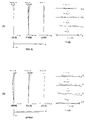
- FIG. 1, FIG. 3, FIG. 5, FIG. 7, and FIG. 9 are cross-sectional views showing the configuration and refractive power distribution of the optical systems OL ⁇ OL (1) to OL (5) ⁇ according to the first to fifth embodiments. be.
- the cross-sectional views of the optical systems OL (1) to OL (5) according to the first to fifth embodiments along the optical axes of the second lens group and the third lens group when focusing on a short-range object from infinity.
- the direction of movement is indicated by an arrow along with the word "focus”.
- the moving direction when a part of the fourth lens group is used as an anti-vibration group to correct image blur is indicated by an arrow together with the characters "anti-vibration".
- each lens group is represented by a combination of reference numerals G and numbers, and each lens is represented by a combination of reference numerals L and numbers.
- the lens group and the like are represented by independently using combinations of the reference numerals and numbers for each embodiment. Therefore, even if the same combination of reference numerals and numbers is used between the examples, it does not mean that they have the same configuration.
- f is the focal length of the entire lens system
- FNO is the F number
- 2 ⁇ is the angle of view (unit is ° (degrees)
- ⁇ is the half angle of view
- Y is the image height.
- TL indicates the distance from the frontmost surface of the lens to the final surface of the lens on the optical axis at infinity, plus Bf
- Bf is the image from the final surface of the lens on the optical axis at infinity.
- the distance to the surface I (back focus) is shown.
- fVR indicates the focal length of the anti-vibration group.
- ⁇ x2 indicates the amount of movement of the second lens group when focusing from an infinity object to a short-distance object.
- ⁇ x3 indicates the amount of movement of the third lens group when focusing from an infinity object to a short-distance object.
- the sign of the amount of movement toward the image plane side is +, and the sign of the amount of movement toward the object side is ⁇ .
- ⁇ 2 indicates the magnification of the second lens group when the object at infinity is in focus.
- ⁇ 3 indicates the magnification of the third lens group when the object at infinity is in focus.
- the plane numbers indicate the order of the optical planes from the object side along the traveling direction of the light beam
- R is the radius of curvature of each optical plane (the plane whose center of curvature is located on the image side).
- D is the distance on the optical axis from each optical surface to the next optical surface (or image surface)
- nd is the refractive index of the material of the optical member with respect to the d line
- ⁇ d is optical.
- the Abbe number and ⁇ gF with respect to the d-line of the material of the member indicate the partial dispersion ratio of the material of the optical member.
- “ ⁇ ” of the radius of curvature indicates a plane or an opening
- (aperture S) indicates an opening aperture S.
- the description of the refractive index nd of air 1.00000 is omitted.
- the refractive index of the material of the optical member is C.
- the partial dispersion ratio ⁇ gF of the material of the optical member is defined by the following equation (A).
- the table of [variable spacing data] shows the surface spacing at the surface number i in which the surface spacing is (Di) in the table of [lens specifications].
- f indicates the focal length of the entire lens system
- ⁇ indicates the photographing magnification.
- the table of [lens group data] shows the starting surface (the surface closest to the object) and the focal length of each lens group.
- mm is generally used for the focal length f, the radius of curvature R, the plane spacing D, other lengths, etc., unless otherwise specified, but the optical system is expanded proportionally. Alternatively, it is not limited to this because the same optical performance can be obtained even if the proportional reduction is performed.
- FIG. 1 is a diagram showing a lens configuration of an optical system according to the first embodiment.
- the optical system OL (1) according to the first embodiment has a first lens group G1 having a positive refractive power and a second lens group G2 having a positive refractive power arranged in order from the object side along the optical axis. It is composed of a third lens group G3 having a negative refractive power and a fourth lens group G4 having a positive refractive power.
- the second lens group G2 moves to the object side along the optical axis
- the third lens group G3 moves to the image side along the optical axis and is adjacent to each other.
- the distance between each lens group changes.
- the first lens group G1 and the fourth lens group G4 are fixed with respect to the image plane I.
- the aperture stop S is arranged between the third lens group G3 and the fourth lens group G4.
- the symbol (+) or ( ⁇ ) attached to each lens group symbol indicates the refractive power of each lens group, and this also applies to all the following examples.
- the first lens group G1 includes a biconvex positive lens L11 arranged in order from the object side along the optical axis, a positive meniscus lens L12 with a convex surface facing the object side, and a biconvex positive lens L13. It is composed of a biconcave negative lens L14, a biconvex positive lens L15, a biconcave negative lens L16, and a junction lens in which a positive meniscus lens L17 with a convex surface facing the object side is joined. ..
- the second lens group G2 is composed of a positive meniscus lens L21 with a convex surface facing the object side.
- the third lens group G3 is composed of a negative meniscus lens L31 having a convex surface facing the object side. That is, the second lens group G2 and the third lens group G3 are composed of two lenses in total.
- a biconcave negative lens L41 arranged in order from the object side along the optical axis, a positive meniscus lens L42 with a concave surface facing the object side, and a biconcave negative lens L43 are joined.
- a negative lens L48 having a concave shape.
- An optical filter FL is arranged between the positive lens L45 in the fourth lens group G4 and the negative meniscus lens L46 (of the junction lens).
- the image plane I is arranged on the image side of the fourth lens group G4.
- the negative lens L41 of the fourth lens group G4, the positive meniscus lens L42, and the negative lens L43 form a vibration-proof group that can move in the direction perpendicular to the optical axis, and image formation due to camera shake or the like. Corrects the displacement of the position (image blur on the image plane I).
- the positive lens L15 of the first lens group G1 corresponds to a positive lens satisfying the above-mentioned conditional expressions (11) to (13).
- the positive meniscus lens L12, the positive lens L13, and the positive meniscus lens L17 of the first lens group G1, the positive meniscus lens L21 of the second lens group G2, and the negative lens L43 of the fourth lens group G4 are the above-mentioned conditional expressions. It corresponds to a lens (specific lens) that satisfies (14).
- Table 1 below lists the values of the specifications of the optical system according to the first embodiment.
- FIG. 2A is a diagram of various aberrations of the optical system according to the first embodiment at the time of infinity focusing.
- FIG. 2B is a diagram of various aberrations of the optical system according to the first embodiment at the time of short-distance focusing.
- FNO indicates an F number
- Y indicates an image height.
- NA indicates the numerical aperture
- Y indicates the image height.
- the spherical aberration diagram shows the value of the F number or numerical aperture corresponding to the maximum aperture
- the astigmatism diagram and the distortion diagram show the maximum image height
- the coma aberration diagram shows the value of each image height. ..
- the solid line shows the sagittal image plane and the broken line shows the meridional image plane.
- the optical system according to the first embodiment has excellent imaging performance in which various aberrations are satisfactorily corrected in the entire range from infinity focusing to short-distance focusing. You can see that.
- FIG. 3 is a diagram showing a lens configuration of an optical system according to a second embodiment.
- the optical system OL (2) according to the second embodiment has a first lens group G1 having a positive refractive power and a second lens group G2 having a positive refractive power arranged in order from the object side along the optical axis. It is composed of a third lens group G3 having a negative refractive power and a fourth lens group G4 having a positive refractive power.
- the second lens group G2 moves to the object side along the optical axis
- the third lens group G3 moves to the image side along the optical axis and is adjacent to each other.
- the distance between each lens group changes.
- the first lens group G1 and the fourth lens group G4 are fixed with respect to the image plane I.
- the aperture stop S is arranged between the third lens group G3 and the fourth lens group G4.
- the first lens group G1 includes a biconvex positive lens L11 arranged in order from the object side along the optical axis, a positive meniscus lens L12 with a convex surface facing the object side, and a biconvex positive lens L13. It is composed of a biconcave negative lens L14, a biconvex positive lens L15, a biconcave negative lens L16, and a junction lens in which a positive meniscus lens L17 with a convex surface facing the object side is joined. ..
- the second lens group G2 is composed of a biconvex positive lens L21.
- the third lens group G3 is composed of a bonded lens (having a negative refractive power) in which a positive meniscus lens L31 having a concave surface facing the object side and a biconcave negative lens L32 are bonded in order from the object side. .. That is, the second lens group G2 and the third lens group G3 are composed of three lenses in total.
- the fourth lens group G4 is a bonded lens in which a positive meniscus lens L41 having a concave surface facing the object side and a negative lens L42 having a concave shape are joined in order from the object side along the optical axis, and a double concave shape.
- a negative meniscus lens L48 with a concave surface facing the object side.
- the image plane I is arranged on the image side of the fourth lens group G4.
- the positive meniscus lens L41 and the negative lens L42 of the fourth lens group G4 and the negative lens L43 form a vibration-proof group that can move in the direction perpendicular to the optical axis, and image formation due to camera shake or the like. Corrects the displacement of the position (image blur on the image plane I).
- the positive lens L15 of the first lens group G1 corresponds to a positive lens satisfying the above-mentioned conditional expressions (11) to (13).
- the positive meniscus lens L12, the positive lens L13, and the positive meniscus lens L17 of the first lens group G1 correspond to lenses (specific lenses) that satisfy the above-mentioned conditional expression (14).
- Table 2 below lists the values of the specifications of the optical system according to the second embodiment.
- FIG. 4A is a diagram of various aberrations of the optical system according to the second embodiment at infinity focusing.
- FIG. 4B is a diagram of various aberrations of the optical system according to the second embodiment at the time of short-distance focusing. From each aberration diagram, the optical system according to the second embodiment has excellent imaging performance in which various aberrations are satisfactorily corrected in the entire range from infinity focusing to short-distance focusing. You can see that.
- FIG. 5 is a diagram showing a lens configuration in an infinity-focused state of the optical system according to the third embodiment.
- the optical system OL (3) according to the third embodiment has a first lens group G1 having a positive refractive power and a second lens group G2 having a positive refractive power arranged in order from the object side along the optical axis. It is composed of a third lens group G3 having a negative refractive power and a fourth lens group G4 having a positive refractive power.
- the second lens group G2 moves to the object side along the optical axis
- the third lens group G3 moves to the image side along the optical axis and is adjacent to each other.
- the distance between each lens group changes.
- the first lens group G1 and the fourth lens group G4 are fixed with respect to the image plane I.
- the aperture stop S is arranged between the third lens group G3 and the fourth lens group G4.
- the first lens group G1 includes a positive meniscus lens L11 having a convex surface facing the object side, a regular meniscus lens L12 having a convex surface facing the object side, and a biconvex positive lens, which are arranged in order from the object side along the optical axis.
- a junction lens in which a lens L13, a biconcave negative lens L14, a biconvex positive lens L15, a biconcave negative lens L16, and a positive meniscus lens L17 with a convex surface facing the object side are joined. Consists of.
- the second lens group G2 is composed of a positive meniscus lens L21 with a convex surface facing the object side.
- the third lens group G3 is composed of a negative meniscus lens L31 having a convex surface facing the object side. That is, the second lens group G2 and the third lens group G3 are composed of two lenses in total.
- the fourth lens group G4 is a bonded lens in which a biconvex positive lens L41, a biconvex positive lens L42, and a biconcave negative lens L43 arranged in order from the object side along the optical axis are joined.
- the image plane I is arranged on the image side of the fourth lens group G4.
- the positive lens L42 and the negative lens L43 of the fourth lens group G4 and the negative lens L44 form a vibration-proof group that can move in the direction perpendicular to the optical axis, and the image formation position due to camera shake or the like.
- Image blur on image plane I is corrected.
- the positive lens L15 of the first lens group G1 corresponds to a positive lens satisfying the above-mentioned conditional expressions (11) to (13).
- the positive meniscus lens L12, the positive lens L13, and the positive meniscus lens L17 of the first lens group G1 correspond to lenses (specific lenses) that satisfy the above-mentioned conditional expression (14).
- Table 3 below lists the values of the specifications of the optical system according to the third embodiment.
- FIG. 6A is a diagram of various aberrations of the optical system according to the third embodiment at the time of infinity focusing.
- FIG. 6B is a diagram of various aberrations of the optical system according to the third embodiment at the time of short-distance focusing. From each aberration diagram, the optical system according to the third embodiment has excellent imaging performance in which various aberrations are satisfactorily corrected in the entire range from infinity focusing to short-distance focusing. You can see that.
- FIG. 7 is a diagram showing a lens configuration in an infinity-focused state of the optical system according to the fourth embodiment.
- the optical system OL (4) according to the fourth embodiment is a first lens group G1 having a positive refractive power, which is arranged in order from the object side along the optical axis and is arranged in order from the object side along the optical axis. It is composed of a second lens group G2 having a positive refractive power, a third lens group G3 having a negative refractive power, and a fourth lens group G4 having a negative refractive power.
- the second lens group G2 moves to the object side along the optical axis
- the third lens group G3 moves to the image side along the optical axis and is adjacent to each other.
- the distance between each lens group changes.
- the first lens group G1 and the fourth lens group G4 are fixed with respect to the image plane I.
- the aperture diaphragm S is arranged in the fourth lens group G4.
- the first lens group G1 includes a positive meniscus lens L11 having a convex surface facing the object side, a biconvex positive lens L12, and a biconvex positive lens L13 arranged in order from the object side along the optical axis.
- a negative meniscus lens L14 having both concave shapes, a positive meniscus lens L15 having a concave surface facing the object side, a negative meniscus lens L16 having a convex surface facing the object side, and a positive meniscus lens L17 having a convex surface facing the object side were joined. It consists of a bonded lens.
- the second lens group G2 is composed of a positive meniscus lens L21 with a convex surface facing the object side.
- the third lens group G3 is composed of a negative meniscus lens L31 having a convex surface facing the object side. That is, the second lens group G2 and the third lens group G3 are composed of two lenses in total.
- the fourth lens group G4 is a bonded lens in which a biconvex positive lens L41, a biconvex positive lens L42, and a biconcave negative lens L43 arranged in order from the object side along the optical axis are joined.
- It is composed of a bonded lens in which a positive lens L48 having a shape and a negative meniscus lens L49 having a concave surface facing the object side are joined, and a negative meniscus lens L50 having a concave surface facing the object side.
- An aperture diaphragm S is arranged between the positive lens L41 in the fourth lens group G4 and the positive lens L42 (of the junction lens).
- the image plane I is arranged on the image side of the fourth lens group G4.
- An optical filter FL is arranged between the negative meniscus lens L50 of the fourth lens group G4 and the image plane I.
- the positive lens L42 and the negative lens L43 of the fourth lens group G4 and the negative lens L44 form a vibration-proof group that can move in the direction perpendicular to the optical axis, and the image formation position due to camera shake or the like.
- Image blur on image plane I is corrected.
- the positive meniscus lens L15 of the first lens group G1 corresponds to a positive lens satisfying the above-mentioned conditional expressions (11) to (13).
- the positive lens L12, the positive lens L13, and the positive meniscus lens L17 of the first lens group G1 and the negative meniscus lens L49 of the fourth lens group G4 are used as lenses (specific lenses) satisfying the above-mentioned conditional expression (14). Applicable.
- Table 4 lists the values of the specifications of the optical system according to the fourth embodiment.
- FIG. 8A is a diagram of various aberrations of the optical system according to the fourth embodiment at the time of infinity focusing.
- FIG. 8B is a diagram of various aberrations of the optical system according to the fourth embodiment at the time of short-distance focusing. From each aberration diagram, the optical system according to the fourth embodiment has excellent imaging performance in which various aberrations are satisfactorily corrected in the entire range from infinity focusing to short-distance focusing. You can see that.
- FIG. 9 is a diagram showing a lens configuration in an infinity-focused state of the optical system according to the fifth embodiment.
- the optical system OL (5) according to the fifth embodiment has a first lens group G1 having a positive refractive power and a second lens group G2 having a positive refractive power arranged in order from the object side along the optical axis. It is composed of a third lens group G3 having a negative refractive power and a fourth lens group G4 having a positive refractive power.
- the second lens group G2 moves to the object side along the optical axis
- the third lens group G3 moves to the image side along the optical axis and is adjacent to each other.
- the distance between each lens group changes.
- the first lens group G1 and the fourth lens group G4 are fixed with respect to the image plane I.
- the aperture stop S is arranged between the third lens group G3 and the fourth lens group G4.
- the first lens group G1 includes a positive meniscus lens L11 having a convex surface facing the object side, a regular meniscus lens L12 having a convex surface facing the object side, and a biconvex positive lens, which are arranged in order from the object side along the optical axis.
- a junction lens in which a lens L13, a biconcave negative lens L14, a biconvex positive lens L15, a biconcave negative lens L16, and a positive meniscus lens L17 with a convex surface facing the object side are joined. Consists of.
- the second lens group G2 is composed of a positive meniscus lens L21 with a convex surface facing the object side.
- the third lens group G3 is composed of a negative meniscus lens L31 having a convex surface facing the object side. That is, the second lens group G2 and the third lens group G3 are composed of two lenses in total.
- the fourth lens group G4 is a bonded lens in which a biconvex positive lens L41, a biconvex positive lens L42, and a biconcave negative lens L43 arranged in order from the object side along the optical axis are joined.
- the image plane I is arranged on the image side of the fourth lens group G4.
- the positive lens L42 and the negative lens L43 of the fourth lens group G4 and the negative lens L44 form a vibration-proof group that can move in the direction perpendicular to the optical axis, and the image formation position due to camera shake or the like.
- image blur on image plane I is corrected.
- the positive lens L15 of the first lens group G1 corresponds to a positive lens satisfying the above-mentioned conditional expressions (11) to (13).
- the positive meniscus lens L12, the positive lens L13, and the positive meniscus lens L17 of the first lens group G1, the positive meniscus lens L21 of the second lens group G2, and the negative lens L43 of the fourth lens group G4 are the above-mentioned conditional expressions. It corresponds to a lens (specific lens) that satisfies (14).
- Table 5 lists the values of the specifications of the optical system according to the fifth embodiment.
- FIG. 10A is a diagram of various aberrations of the optical system according to the fifth embodiment at the time of infinity focusing.
- FIG. 10B is a diagram of various aberrations of the optical system according to the fifth embodiment at the time of short-distance focusing. From each aberration diagram, the optical system according to the fifth embodiment has excellent imaging performance in which various aberrations are satisfactorily corrected in the entire range from infinity focusing to short-distance focusing. You can see that.
- Conditional expression (1) 0.010 ⁇ ( ⁇ x2A + ⁇ x3A) / D1 ⁇ 0.200
- Conditional expression (2) -0.20 ⁇ x2 / f2 ⁇ 0.00
- Conditional expression (3) -0.20 ⁇ x3 / f3 ⁇ 0.00
- Conditional expression (4) 1.00 ⁇ f2 / (-f3) ⁇ 4.00
- Conditional expression (5) -3.00 ⁇ x2 / ⁇ x3 ⁇ -0.20
- Conditional expression (6) -8.50 ⁇ f1 / fVR ⁇ -3.00
- Conditional expression (7) 0.45 ⁇ 2 ⁇ 0.80
- Conditional expression (8) 0.20 ⁇ 1 / ⁇ 3 ⁇ 0.50
- Conditional expression (9) ⁇ 2 + (1 / ⁇ 2) ⁇ -2 ⁇ 0.25
- Conditional expression (10) ⁇ 3 + (1 / ⁇ 3)
- a four-group configuration is shown, but the present application is not limited to this, and an optical system having another group configuration (for example, five groups, etc.) can also be configured.
- an optical system having another group configuration for example, five groups, etc.
- the lens group refers to a portion having at least one lens separated by an air interval that changes at the time of focusing.
- a configuration having an anti-vibration function is shown, but the present application is not limited to this, and a configuration having no anti-vibration function is also possible.
- the lens surface may be formed of a spherical surface or a flat surface, or may be formed of an aspherical surface.
- lens processing and assembly adjustment are facilitated, and deterioration of optical performance due to processing and assembly adjustment errors can be prevented, which is preferable. Further, even if the image plane is displaced, the deterioration of the depiction performance is small, which is preferable.
- the aspherical surface is an aspherical surface formed by grinding, a glass mold aspherical surface formed by forming glass into an aspherical surface shape, or a composite aspherical surface formed by forming resin on the glass surface into an aspherical surface shape. It doesn't matter which one. Further, the lens surface may be a diffraction surface, and the lens may be a refractive index distribution type lens (GRIN lens) or a plastic lens.
- GRIN lens refractive index distribution type lens
- the aperture diaphragm is preferably arranged between the third lens group and the fourth lens group, or within the fourth lens group, but the role of the aperture diaphragm is substituted by the lens frame without providing the member as the aperture diaphragm. You may.
- Each lens surface may be provided with an antireflection film having high transmittance in a wide wavelength range in order to reduce flare and ghost and achieve high contrast optical performance.
- G1 1st lens group G2 2nd lens group G3 3rd lens group G4 4th lens group I image plane S aperture stop
Landscapes
- Physics & Mathematics (AREA)
- General Physics & Mathematics (AREA)
- Optics & Photonics (AREA)
- Nonlinear Science (AREA)
- Lenses (AREA)
Abstract
光学系(OL)は、光軸に沿って物体側から順に並んだ、正の屈折力を有する第1レンズ群(G1)と、第2レンズ群(G2)と、第3レンズ群(G3)と、第4レンズ群(G4)とを有し、無限遠物体から近距離物体への合焦の際、第2レンズ群(G2)と第3レンズ群(G3)とが光軸に沿って互いに異なる軌跡で移動し、第2レンズ群(G2)と第3レンズ群(G3)とが合わせて3個以下のレンズから構成される。
Description
本発明は、光学系、光学機器、および光学系の製造方法に関する。
従来から、デジタルスチルカメラやビデオカメラ等に適した光学系が提案されている(例えば、特許文献1を参照)。このような光学系においては、無限遠合焦時から近距離合焦時まで優れた光学性能を維持することが求められている。
第1の本発明に係る光学系は、光軸に沿って物体側から順に並んだ、正の屈折力を有する第1レンズ群と、第2レンズ群と、第3レンズ群と、第4レンズ群とを有し、無限遠物体から近距離物体への合焦の際、前記第2レンズ群と前記第3レンズ群とが光軸に沿って互いに異なる軌跡で移動し、前記第2レンズ群と前記第3レンズ群とが合わせて3個以下のレンズから構成される。
第2の本発明に係る光学系は、光軸に沿って物体側から順に並んだ、正の屈折力を有する第1レンズ群と、第2レンズ群と、第3レンズ群と、第4レンズ群とを有し、無限遠物体から近距離物体への合焦の際、前記第2レンズ群と前記第3レンズ群とが光軸に沿って互いに異なる軌跡で移動し、以下の条件式を満足する。
0.010<(Δx2A+Δx3A)/D1<0.200
但し、Δx2A:無限遠物体から近距離物体への合焦の際の前記第2レンズ群の移動量の絶対値
Δx3A:無限遠物体から近距離物体への合焦の際の前記第3レンズ群の移動量の絶対値
D1:前記第1レンズ群の光軸上の長さ
0.010<(Δx2A+Δx3A)/D1<0.200
但し、Δx2A:無限遠物体から近距離物体への合焦の際の前記第2レンズ群の移動量の絶対値
Δx3A:無限遠物体から近距離物体への合焦の際の前記第3レンズ群の移動量の絶対値
D1:前記第1レンズ群の光軸上の長さ
本発明に係る光学機器は、上記光学系を備えて構成される。
本発明に係る光学系の製造方法は、光軸に沿って物体側から順に並んだ、正の屈折力を有する第1レンズ群と、第2レンズ群と、第3レンズ群と、第4レンズ群とを有する光学系の製造方法であって、無限遠物体から近距離物体への合焦の際、前記第2レンズ群と前記第3レンズ群とが光軸に沿って互いに異なる軌跡で移動し、前記第2レンズ群と前記第3レンズ群とが合わせて3個以下のレンズから構成されるように、レンズ鏡筒内に各レンズを配置する。
以下、本発明に係る好ましい実施形態について説明する。まず、各実施形態に係る光学系を備えたカメラ(光学機器)を図11に基づいて説明する。このカメラ1は、図11に示すように、本体2と、本体2に装着される撮影レンズ3により構成される。本体2は、撮像素子4と、デジタルカメラの動作を制御する本体制御部(不図示)と、液晶画面5とを備える。撮影レンズ3は、複数のレンズ群からなる光学系OLと、各レンズ群の位置を制御するレンズ位置制御機構(不図示)とを備える。レンズ位置制御機構は、レンズ群の位置を検出するセンサと、レンズ群を光軸に沿って前後に移動させるモータと、モータを駆動する制御回路などにより構成される。
被写体からの光は、撮影レンズ3の光学系OLにより集光されて、撮像素子4の像面I上に到達する。像面Iに到達した被写体からの光は、撮像素子4により光電変換され、デジタル画像データとして不図示のメモリに記録される。メモリに記録されたデジタル画像データは、ユーザの操作に応じて液晶画面5に表示することが可能である。なお、このカメラは、ミラーレスカメラでも、クイックリターンミラーを有した一眼レフタイプのカメラであっても良い。また、図11に示す光学系OLは、撮影レンズ3に備えられる光学系を模式的に示したものであり、光学系OLのレンズ構成はこの構成に限定されるものではない。
次に、第1実施形態に係る光学系について説明する。第1実施形態に係る光学系(撮影レンズ)OLの一例としての光学系OL(1)は、図1に示すように、光軸に沿って物体側から順に並んだ、正の屈折力を有する第1レンズ群G1と、第2レンズ群G2と、第3レンズ群G3と、第4レンズ群G4とを有して構成される。無限遠物体から近距離物体への合焦(フォーカシング)の際、第2レンズ群G2と第3レンズ群G3とが光軸に沿って互いに異なる軌跡で移動する。また、第2レンズ群G2と第3レンズ群G3とが合わせて3個以下のレンズから構成される。
第1実施形態によれば、無限遠合焦時から近距離合焦時まで優れた光学性能を有する光学系、およびこの光学系を備えた光学機器を得ることが可能になる。第1実施形態に係る光学系OLは、図3に示す光学系OL(2)でも良く、図5に示す光学系OL(3)でも良く、図7に示す光学系OL(4)でも良く、図9に示す光学系OL(5)でも良い。
次に、第2実施形態に係る光学系について説明する。第2実施形態に係る光学系(撮影レンズ)OLの一例としての光学系OL(1)は、図1に示すように、光軸に沿って物体側から順に並んだ、正の屈折力を有する第1レンズ群G1と、第2レンズ群G2と、第3レンズ群G3と、第4レンズ群G4とを有して構成される。無限遠物体から近距離物体への合焦(フォーカシング)の際、第2レンズ群G2と第3レンズ群G3とが光軸に沿って互いに異なる軌跡で移動する。
上記構成の下、第2実施形態に係る光学系OLは、以下の条件式(1)を満足する。
0.010<(Δx2A+Δx3A)/D1<0.200 ・・・(1)
但し、Δx2A:無限遠物体から近距離物体への合焦の際の第2レンズ群G2の移動量の絶対値
Δx3A:無限遠物体から近距離物体への合焦の際の第3レンズ群G3の移動量の絶対値
D1:第1レンズ群G1の光軸上の長さ
0.010<(Δx2A+Δx3A)/D1<0.200 ・・・(1)
但し、Δx2A:無限遠物体から近距離物体への合焦の際の第2レンズ群G2の移動量の絶対値
Δx3A:無限遠物体から近距離物体への合焦の際の第3レンズ群G3の移動量の絶対値
D1:第1レンズ群G1の光軸上の長さ
第2実施形態によれば、無限遠合焦時から近距離合焦時まで優れた光学性能を有する光学系、およびこの光学系を備えた光学機器を得ることが可能になる。第2実施形態に係る光学系OLは、図3に示す光学系OL(2)でも良く、図5に示す光学系OL(3)でも良く、図7に示す光学系OL(4)でも良く、図9に示す光学系OL(5)でも良い。
条件式(1)は、合焦の際の第2レンズ群G2の移動量と第3レンズ群G3の移動量の和と、第1レンズ群G1の光軸上の長さとの適切な関係を規定するものである。条件式(1)を満足することで、無限遠物体から近距離物体への合焦の際の収差変動を抑えることができる。
条件式(1)の対応値が下限値を下回ると、合焦を行う第2レンズ群G2および第3レンズ群G3の移動量が小さくなることで、第2レンズ群G2および第3レンズ群G3のパワーが強くなる傾向になるため、合焦の際の収差変動を抑えることが困難になる。条件式(1)の下限値を、0.015、0.020、0.025、0.030、0.035、0.040、さらに0.042に設定することで、本実施形態の効果をより確実なものとすることができる。
条件式(1)の対応値が上限値を上回ると、第1レンズ群G1が短くなることで、第1レンズ群G1のパワーが強くなる傾向になるため、軸上色収差や球面収差等の諸収差を補正することが困難になる。条件式(1)の上限値を、0.175、0.160、0.150、0.125、0.115、0.110、さらに0.100に設定することで、本実施形態の効果をより確実なものとすることができる。
第1実施形態および第2実施形態に係る光学系OLは、以下の条件式(2)を満足することが望ましい。
-0.20<Δx2/f2<0.00 ・・・(2)
但し、Δx2:無限遠物体から近距離物体への合焦の際の第2レンズ群G2の移動量(像面側への移動量の符号を+とし、物体側への移動量の符号を-とする)
f2:第2レンズ群G2の焦点距離
-0.20<Δx2/f2<0.00 ・・・(2)
但し、Δx2:無限遠物体から近距離物体への合焦の際の第2レンズ群G2の移動量(像面側への移動量の符号を+とし、物体側への移動量の符号を-とする)
f2:第2レンズ群G2の焦点距離
条件式(2)は、合焦の際の第2レンズ群G2の移動量と、第2レンズ群G2の焦点距離との適切な関係を規定するものである。条件式(2)を満足することで、無限遠物体から近距離物体への合焦の際の収差変動を抑えることができる。
条件式(2)の対応値が下限値を下回ると、合焦を行う第2レンズ群G2のパワーが強くなることで、合焦の際の収差変動を抑えることが困難になる。また、合焦を行う第2レンズ群G2の移動量が大きくなることで、光学系OLの全長の増大を招く。光学系OLの全長の増大を抑えるため、例えば第1レンズ群G1を短くして、第1レンズ群G1のパワーを強くする必要があることから、軸上色収差や球面収差等の諸収差を補正することが困難になる。条件式(2)の下限値を、-0.18、-0.15、-0.13、-0.10、-0.09、さらに-0.08に設定することで、各実施形態の効果をより確実なものとすることができる。
条件式(2)の対応値が上限値に達すると、合焦を行う第2レンズ群G2のパワーもしくは移動量を確保することが困難になり、好ましくない。条件式(2)の上限値を-0.01、さらに-0.02に設定することで、各実施形態の効果をより確実なものとすることができる。
第1実施形態および第2実施形態に係る光学系OLは、以下の条件式(3)を満足することが望ましい。
-0.20<Δx3/f3<0.00 ・・・(3)
但し、Δx3:無限遠物体から近距離物体への合焦の際の第3レンズ群G3の移動量(像面側への移動量の符号を+とし、物体側への移動量の符号を-とする)
f3:第3レンズ群G3の焦点距離
-0.20<Δx3/f3<0.00 ・・・(3)
但し、Δx3:無限遠物体から近距離物体への合焦の際の第3レンズ群G3の移動量(像面側への移動量の符号を+とし、物体側への移動量の符号を-とする)
f3:第3レンズ群G3の焦点距離
条件式(3)は、合焦の際の第3レンズ群G3の移動量と、第3レンズ群G3の焦点距離との適切な関係を規定するものである。条件式(3)を満足することで、無限遠物体から近距離物体への合焦の際の収差変動を抑えることができる。
条件式(3)の対応値が下限値を下回ると、合焦を行う第3レンズ群G3のパワーが強くなることで、合焦の際の収差変動を抑えることが困難になる。また、合焦を行う第3レンズ群G3の移動量が大きくなることで、光学系OLの全長の増大を招く。光学系OLの全長の増大を抑えるため、例えば第1レンズ群G1を短くして、第1レンズ群G1のパワーを強くする必要があることから、軸上色収差や球面収差等の諸収差を補正することが困難になる。条件式(3)の下限値を、-0.18、-0.16、さらに-0.15に設定することで、各実施形態の効果をより確実なものとすることができる。
条件式(3)の対応値が上限値に達すると、合焦を行う第3レンズ群G3のパワーもしくは移動量を確保することが困難になり、好ましくない。条件式(3)の上限値を-0.01に設定することで、各実施形態の効果をより確実なものとすることができる。
第1実施形態および第2実施形態に係る光学系OLは、以下の条件式(4)を満足することが望ましい。
1.00<f2/(-f3)<4.00 ・・・(4)
但し、f2:第2レンズ群G2の焦点距離
f3:第3レンズ群G3の焦点距離
1.00<f2/(-f3)<4.00 ・・・(4)
但し、f2:第2レンズ群G2の焦点距離
f3:第3レンズ群G3の焦点距離
条件式(4)は、第2レンズ群G2の焦点距離と、第3レンズ群G3の焦点距離との適切な関係を規定するものである。条件式(4)を満足することで、無限遠物体から近距離物体への合焦の際の収差変動を抑えることができる。
条件式(4)の対応値が下限値を下回ると、合焦を行う第2レンズ群G2のパワーが強くなるため、合焦の際の収差変動を抑えることが困難になる。条件式(4)の下限値を、1.05、1.10、1.15、1.20、1.25、1.30、さらに1.35に設定することで、各実施形態の効果をより確実なものとすることができる。
条件式(4)の対応値が上限値を上回ると、合焦を行う第3レンズ群G3のパワーが強くなるため、合焦の際の収差変動を抑えることが困難になる。条件式(4)の上限値を、3.80、3.50、3.25、3.00、2.85、2.80、2.75、さらに2.70に設定することで、各実施形態の効果をより確実なものとすることができる。
第1実施形態および第2実施形態に係る光学系OLは、以下の条件式(5)を満足することが望ましい。
-3.00<Δx2/Δx3<-0.20 ・・・(5)
但し、Δx2:無限遠物体から近距離物体への合焦の際の第2レンズ群G2の移動量(像面側への移動量の符号を+とし、物体側への移動量の符号を-とする)
Δx3:無限遠物体から近距離物体への合焦の際の第3レンズ群G3の移動量(像面側への移動量の符号を+とし、物体側への移動量の符号を-とする)
-3.00<Δx2/Δx3<-0.20 ・・・(5)
但し、Δx2:無限遠物体から近距離物体への合焦の際の第2レンズ群G2の移動量(像面側への移動量の符号を+とし、物体側への移動量の符号を-とする)
Δx3:無限遠物体から近距離物体への合焦の際の第3レンズ群G3の移動量(像面側への移動量の符号を+とし、物体側への移動量の符号を-とする)
条件式(5)は、合焦の際の第2レンズ群G2の移動量と、合焦の際の第3レンズ群G3の移動量との適切な関係を規定するものである。条件式(5)を満足することで、軸上色収差や球面収差等の諸収差を良好に補正することができる。
条件式(5)の対応値が下限値を下回ると、合焦を行う第2レンズ群G2の移動量が大きくなることで、光学系OLの全長の増大を招く。光学系OLの全長の増大を抑えるため、例えば第1レンズ群G1を短くして、第1レンズ群G1のパワーを強くする必要があることから、軸上色収差や球面収差等の諸収差を補正することが困難になる。条件式(5)の下限値を、-2.85、-2.70、-2.60、-2.50、-2.45、さらに-2.40に設定することで、各実施形態の効果をより確実なものとすることができる。
条件式(5)の対応値が上限値を上回ると、合焦を行う第3レンズ群G3の移動量が大きくなることで、光学系OLの全長の増大を招く。光学系OLの全長の増大を抑えるため、例えば第1レンズ群G1を短くして、第1レンズ群G1のパワーを強くする必要があることから、軸上色収差や球面収差等の諸収差を補正することが困難になる。条件式(5)の上限値を、-0.25、-0.30、-0.35、-0.40、-0.45、さらに-0.50に設定することで、各実施形態の効果をより確実なものとすることができる。
第1実施形態および第2実施形態に係る光学系OLにおいて、第4レンズ群G4は、像ブレを補正するために光軸と垂直な方向の変位成分を有するように移動可能な負の屈折力を有する防振群を有することが望ましい。これにより、像ブレを補正する際の収差変動を抑えることができる。
第1実施形態および第2実施形態に係る光学系OLにおいて、防振群は、2個以上のレンズから構成されることが望ましい。これにより、像ブレを補正する際の収差変動を抑えることができる。
第1実施形態および第2実施形態に係る光学系OLは、以下の条件式(6)を満足することが望ましい。
-8.50<f1/fVR<-3.00 ・・・(6)
但し、f1:第1レンズ群G1の焦点距離
fVR:防振群の焦点距離
-8.50<f1/fVR<-3.00 ・・・(6)
但し、f1:第1レンズ群G1の焦点距離
fVR:防振群の焦点距離
条件式(6)は、第1レンズ群G1の焦点距離と、防振群の焦点距離との適切な関係を規定するものである。条件式(6)を満足することで、像ブレを補正する際の収差変動を抑えることができる。
条件式(6)の対応値が下限値を下回ると、防振群のパワーが強くなるため、像ブレを補正する際の収差変動を抑えることが困難になる。条件式(6)の下限値を、-8.25、-8.10、-8.00、-7.85.-7.70、-7.50、-7.30、さらに-7.25に設定することで、各実施形態の効果をより確実なものとすることができる。
条件式(6)の対応値が上限値を上回ると、第1レンズ群G1のパワーが強くなるため、軸上色収差や球面収差等の諸収差を補正することが困難になる。条件式(6)の上限値を、-3.15、-3.30、-3.50、-3.65、-3.80、-4.00、-4.10、-4.20、さらに-4.25に設定することで、各実施形態の効果をより確実なものとすることができる。
第1実施形態および第2実施形態に係る光学系OLは、以下の条件式(7)を満足することが望ましい。
0.45<β2<0.80 ・・・(7)
但し、β2:無限遠物体合焦時の第2レンズ群G2の倍率
0.45<β2<0.80 ・・・(7)
但し、β2:無限遠物体合焦時の第2レンズ群G2の倍率
条件式(7)は、無限遠物体合焦時の第2レンズ群G2の倍率について適切な範囲を規定するものである。条件式(7)を満足することで、合焦の際の球面収差をはじめとする諸収差の変動を抑えることができる。
条件式(7)の対応値が下限値を下回ると、合焦の際の諸収差の変動を抑えることが困難になる。条件式(7)の下限値を、0.46、0.47、0.48、さらに0.49に設定することで、各実施形態の効果をより確実なものとすることができる。
条件式(7)の対応値が上限値を上回ると、合焦の際の諸収差の変動を抑えることが困難になる。条件式(7)の上限値を、0.78、0.75、0.73、さらに0.70に設定することで、各実施形態の効果をより確実なものとすることができる。
第1実施形態および第2実施形態に係る光学系OLは、以下の条件式(8)を満足することが望ましい。
0.20<1/β3<0.50 ・・・(8)
但し、β3:無限遠物体合焦時の第3レンズ群G3の倍率
0.20<1/β3<0.50 ・・・(8)
但し、β3:無限遠物体合焦時の第3レンズ群G3の倍率
条件式(8)は、無限遠物体合焦時の第3レンズ群G3の倍率について適切な範囲を規定するものである。条件式(8)を満足することで、合焦の際の球面収差をはじめとする諸収差の変動を抑えることができる。
条件式(8)の対応値が下限値を下回ると、合焦の際の諸収差の変動を抑えることが困難になる。条件式(8)の下限値を、0.22、0.24、0.25、さらに0.26に設定することで、各実施形態の効果をより確実なものとすることができる。
条件式(8)の対応値が上限値を上回ると、合焦の際の諸収差の変動を抑えることが困難になる。条件式(8)の上限値を、0.48、0.46、0.45、さらに0.44に設定することで、各実施形態の効果をより確実なものとすることができる。
第1実施形態および第2実施形態に係る光学系OLは、以下の条件式(9)を満足することが望ましい。
{β2+(1/β2)}-2<0.25 ・・・(9)
但し、β2:無限遠物体合焦時の第2レンズ群G2の倍率
{β2+(1/β2)}-2<0.25 ・・・(9)
但し、β2:無限遠物体合焦時の第2レンズ群G2の倍率
条件式(9)は、無限遠物体合焦時の第2レンズ群G2の倍率について適切な範囲を規定するものである。条件式(9)を満足することで、合焦の際の球面収差、歪曲収差、およびコマ収差等の諸収差の変動を抑えつつ、フォーカス群の移動量を小さくすることができる。
条件式(9)の対応値が条件式範囲内にあることが好ましく、条件式(9)の下限値を仮に、0.10、0.12、0.14、さらに0.15に設定するならば、各実施形態の効果をより確実なものとすることができる。
条件式(9)の対応値が上限値を上回ると、合焦の際の諸収差の変動を抑えることが困難になる。条件式(9)の上限値を0.24、さらに0.23に設定することで、各実施形態の効果をより確実なものとすることができる。
第1実施形態および第2実施形態に係る光学系OLは、以下の条件式(10)を満足することが望ましい。
{β3+(1/β3)}-2<0.18 ・・・(10)
但し、β3:無限遠物体合焦時の第3レンズ群G3の倍率
{β3+(1/β3)}-2<0.18 ・・・(10)
但し、β3:無限遠物体合焦時の第3レンズ群G3の倍率
条件式(10)は、無限遠物体合焦時の第3レンズ群G3の倍率について適切な範囲を規定するものである。条件式(10)を満足することで、合焦の際の球面収差、歪曲収差、およびコマ収差等の諸収差の変動を抑えつつ、フォーカス群の移動量を小さくすることができる。
条件式(10)の対応値が条件式範囲内にあることが好ましく、条件式(10)の下限値を仮に、0.03、さらに0.05に設定するならば、各実施形態の効果をより確実なものとすることができる。
条件式(10)の対応値が上限値を上回ると、合焦の際の諸収差の変動を抑えることが困難になる。条件式(10)の上限値を、0.16、0.15、さらに0.14に設定することで、各実施形態の効果をより確実なものとすることができる。
第1実施形態および第2実施形態に係る光学系OLにおいて、第1レンズ群G1は、以下の条件式(11)~(13)を満足する正レンズ(L15)を有することが望ましい。
ndL1+(0.01425×νdL1)<2.12 ・・・(11)
νdL1<35.00 ・・・(12)
0.702<θgFL1+(0.00316×νdL1)・・・(13)
但し、ndL1:正レンズのd線に対する屈折率
νdL1:正レンズのd線を基準とするアッベ数
θgFL1:正レンズの部分分散比であり、正レンズのg線に対する屈折率をngL1とし、正レンズのF線に対する屈折率をnFL1とし、正レンズのC線に対する屈折率をnCL1としたとき、次式で定義される
θgFL1=(ngL1-nFL1)/(nFL1-nCL1)
なお、正レンズのd線を基準とするアッベ数νdL1は、次式で定義される
νdL1=(ndL1-1)/(nFL1-nCL1)
条件式(11)は、第1レンズ群G1における正レンズのd線に対する屈折率と、正レンズのd線を基準とするアッベ数との適切な関係を規定するものである。条件式(11)を満足することで、球面収差、コマ収差等の基準収差の補正と、1次の色収差の補正(色消し)を良好に行うことができる。
条件式(11)の対応値が上限値を上回ると、例えばペッツバール和が小さくなることで、像面湾曲の補正が困難になるため、好ましくない。条件式(11)の上限値を、2.11、2.10、2.09、2.08、2.07、さらに2.06に設定することで、各実施形態の効果をより確実なものとすることができる。
条件式(11)の下限値を1.83に設定してもよい。条件式(11)の対応値がこの下限値を下回ると、基準収差および色収差の補正が過剰となり、好ましくない。条件式(11)の下限値を、1.85、1.90、1.95、さらに1.98に設定することで、各実施形態の効果をより確実なものとすることができる。
条件式(12)は、第1レンズ群G1における正レンズのd線を基準とするアッベ数の適切な範囲を規定するものである。条件式(12)を満足することで、球面収差、コマ収差等の基準収差の補正と、1次の色収差の補正(色消し)を良好に行うことができる。
条件式(12)の対応値が上限値を上回ると、例えば正レンズより像面側に配置されたレンズ群において軸上色収差の補正が困難となるため、好ましくない。条件式(12)の上限値を、32.50、32.00、31.50、31.00、30.50、30.00、さらに29.50に設定することで、各実施形態の効果をより確実なものとすることができる。
条件式(12)の下限値を18.00に設定してもよい。条件式(12)の対応値がこの下限値を下回ると、基準収差および色収差の補正が過剰となり、好ましくない。条件式(12)の下限値を、18.50、19.00、19.50、さらに20.00に設定することで、各実施形態の効果をより確実なものとすることができる。
条件式(13)は、第1レンズ群G1における正レンズの異常分散性を適切に規定するものである。条件式(13)を満足することで、色収差の補正において、1次の色消しに加え、2次スペクトルを良好に補正することができる。
条件式(13)の対応値が下限値を下回ると、正レンズの異常分散性が小さくなるため、色収差の補正が困難となる。条件式(13)の下限値を、0.704、0.708、0.710、0.712、さらに0.715に設定することで、各実施形態の効果をより確実なものとすることができる。
条件式(13)の上限値を0.900に設定してもよい。条件式(13)の対応値がこの上限値を上回ると、色収差の補正が過剰となり、好ましくない。条件式(13)の上限値を、0.880、0.850、0.825、さらに0.800に設定することで、各実施形態の効果をより確実なものとすることができる。
第1実施形態および第2実施形態に係る光学系OLは、以下の条件式(14)を満足するレンズ(L12,L13)を有することが望ましい。なお、他のレンズと区別するため、条件式(14)を満足するレンズを特定レンズと称する場合がある。
80.00<νdL2 ・・・(14)
但し、νdL2:特定レンズのd線を基準とするアッベ数
80.00<νdL2 ・・・(14)
但し、νdL2:特定レンズのd線を基準とするアッベ数
条件式(14)は、特定レンズのd線を基準とするアッベ数の適切な範囲を規定するものである。条件式(14)を満足することで、軸上色収差や倍率色収差を良好に補正することができる。
条件式(14)の対応値が下限値を下回ると、軸上色収差や倍率色収差を補正することが困難になる。条件式(14)の下限値を、81.00、81.80、82.50、84.00、85.50、87.00、さらに90.00に設定することで、各実施形態の効果をより確実なものとすることができる。
条件式(14)の上限値を110.00に設定してもよい。条件式(14)の対応値がこの上限値を上回ると、軸上色収差や倍率色収差の補正が過剰となり、好ましくない。条件式(14)の上限値を、107.50、105.00、102.50、100.00、さらに98.00に設定することで、各実施形態の効果をより確実なものとすることができる。
第1実施形態および第2実施形態に係る光学系OLは、以下の条件式(15)を満足することが望ましい。
3.50°<2ω<8.50° ・・・(15)
但し、2ω:光学系OLの全画角
3.50°<2ω<8.50° ・・・(15)
但し、2ω:光学系OLの全画角
条件式(15)は、光学系OLの全画角の適切な範囲を規定するものである。条件式(15)を満足することで、焦点距離の長い望遠型の光学系が得られるので好ましい。条件式(15)の下限値を3.80°、さらに4.00°に設定することで、各実施形態の効果をより確実なものとすることができる。また、条件式(15)の上限値を、8.00°、7.50°、7.00°、さらに6.50°に設定することで、各実施形態の効果をより確実なものとすることができる。
第1実施形態および第2実施形態に係る光学系OLにおいて、無限遠物体から近距離物体への合焦の際、第2レンズ群G2が光軸に沿って物体側へ移動し、第3レンズ群G3が光軸に沿って像面側へ移動することが望ましい。これにより、無限遠物体から近距離物体への合焦の際の収差変動を良好に補正することが可能になる。また、光学系OLのスペースを有効に使うことができ、良好な光学性能を保ちつつ光学系OLの全長を短く抑えることが可能になる。
第1実施形態および第2実施形態に係る光学系OLにおいて、第2レンズ群G2は、1個のレンズから構成されることが望ましい。これにより、第2レンズ群G2が軽量になるため、無限遠物体から近距離物体への合焦を高速で行うことが可能になる。また、フォーカス群の軽量化のためにレンズ径を小さくする必要がないため、例えば第1レンズ群G1のパワーが強くなりすぎることがなく、軸上色収差や球面収差等の諸収差を良好に補正することが可能である。
第1実施形態および第2実施形態に係る光学系OLにおいて、第3レンズ群G3は、1個のレンズ成分から構成されることが望ましい。これにより、第3レンズ群G3が軽量になるため、無限遠物体から近距離物体への合焦を高速で行うことが可能になる。また、フォーカス群の軽量化のためにレンズ径を小さくする必要がないため、例えば第1レンズ群G1のパワーが強くなりすぎることがなく、軸上色収差や球面収差等の諸収差を良好に補正することが可能である。なお、各実施形態において、レンズ成分は、単レンズ又は接合レンズを示すものである。
第1実施形態および第2実施形態に係る光学系OLは、第2レンズ群G2よりも像面側に配置された絞り(開口絞りS)を有することが望ましい。これにより、光学系OLにおいて光束の径が小さくなる箇所に絞りが配置されるため、鏡筒の外径を小型化することが可能になる。
さらに、絞り(開口絞りS)が第3レンズ群G3よりも像面側に配置されることが望ましい。これにより、光学系OLにおいて光束の径が小さくなる箇所に絞りが配置されるため、鏡筒の外径を小型化することが可能になる。
第1実施形態および第2実施形態に係る光学系OLにおいて、第2レンズ群G2が合焦の際に移動する第1の合焦レンズ群であるが、第1の合焦レンズ群は、正の屈折力を有してもよく、負の屈折力を有してもよい。また、第3レンズ群G3が合焦の際に移動する第2の合焦レンズ群であるが、第2の合焦レンズ群は、正の屈折力を有してもよく、負の屈折力を有してもよい。
第1実施形態および第2実施形態に係る光学系OLにおいて、第2レンズ群G2が合焦の際に移動する第1の合焦レンズ群であり、第3レンズ群G3が合焦の際に移動する第2の合焦レンズ群であるが、第1の合焦レンズ群と第2の合焦レンズ群との間に、正または負の屈折力を有するレンズが1つ以上設けられてもよい。
続いて、図12を参照しながら、第1実施形態に係る光学系OLの製造方法について概説する。まず、光軸に沿って物体側から順に、正の屈折力を有する第1レンズ群G1と、第2レンズ群G2と、第3レンズ群G3と、第4レンズ群G4とを配置する(ステップST1)。次に、無限遠物体から近距離物体への合焦の際、第2レンズ群G2と第3レンズ群G3とが光軸に沿って互いに異なる軌跡で移動するように構成する(ステップST2)。また、第2レンズ群G2と第3レンズ群G3とが合わせて3個以下のレンズから構成されるように、レンズ鏡筒内に各レンズを配置する。このような製造方法によれば、無限遠合焦時から近距離合焦時まで優れた光学性能を有する光学系を製造することが可能になる。続いて、第1実施形態の場合と同様に図12を参照しながら、第2実施形態に係る光学系OLの製造方法について概説する。まず、光軸に沿って物体側から順に、正の屈折力を有する第1レンズ群G1と、第2レンズ群G2と、第3レンズ群G3と、第4レンズ群G4とを配置する(ステップST1)。次に、無限遠物体から近距離物体への合焦の際、第2レンズ群G2と第3レンズ群G3とが光軸に沿って互いに異なる軌跡で移動するように構成する(ステップST2)。また、少なくとも上記条件式(1)を満足するように、レンズ鏡筒内に各レンズを配置する。このような製造方法によれば、無限遠合焦時から近距離合焦時まで優れた光学性能を有する光学系を製造することが可能になる。
以下、各実施形態の実施例に係る光学系OLを図面に基づいて説明する。図1、図3、図5、図7、図9は、第1~第5実施例に係る光学系OL{OL(1)~OL(5)}の構成及び屈折力配分を示す断面図である。第1~第5実施例に係る光学系OL(1)~OL(5)の断面図では、無限遠から近距離物体へ合焦する際の第2レンズ群および第3レンズ群の光軸に沿った移動方向を、「合焦」という文字とともに矢印で示している。また、第4レンズ群の一部が防振群として像ブレを補正する際の移動方向を、「防振」という文字とともに矢印で示している。
これら図1、図3、図5、図7、図9において、各レンズ群を符号Gと数字の組み合わせにより、各レンズを符号Lと数字の組み合わせにより、それぞれ表している。この場合において、符号、数字の種類および数が大きくなって煩雑化するのを防止するため、実施例毎にそれぞれ独立して符号と数字の組み合わせを用いてレンズ群等を表している。このため、実施例間で同一の符号と数字の組み合わせが用いられていても、同一の構成であることを意味するものでは無い。
以下に表1~表5を示すが、この内、表1は第1実施例、表2は第2実施例、表3は第3実施例、表4は第4実施例、表5は第5実施例における各諸元データを示す表である。各実施例では収差特性の算出対象として、d線(波長λ=587.6nm)、g線(波長λ=435.8nm)を選んでいる。
[全体諸元]の表において、fはレンズ全系の焦点距離、FNОはFナンバー、2ωは画角(単位は°(度)で、ωが半画角である)、Yは像高を示す。TLは無限遠合焦時の光軸上でのレンズ最前面からレンズ最終面までの距離にBfを加えた距離を示し、Bfは無限遠合焦時の光軸上でのレンズ最終面から像面Iまでの距離(バックフォーカス)を示す。また、[全体諸元]の表において、fVRは、防振群の焦点距離を示す。Δx2は、無限遠物体から近距離物体への合焦の際の第2レンズ群の移動量を示す。Δx3は、無限遠物体から近距離物体への合焦の際の第3レンズ群の移動量を示す。なお、レンズ群の移動量については、像面側への移動量の符号を+とし、物体側への移動量の符号を-とする。β2は、無限遠物体合焦時の第2レンズ群の倍率を示す。β3は、無限遠物体合焦時の第3レンズ群の倍率を示す。
[レンズ諸元]の表において、面番号は光線の進行する方向に沿った物体側からの光学面の順序を示し、Rは各光学面の曲率半径(曲率中心が像側に位置する面を正の値としている)、Dは各光学面から次の光学面(又は像面)までの光軸上の距離である面間隔、ndは光学部材の材料のd線に対する屈折率、νdは光学部材の材料のd線を基準とするアッベ数、θgFは光学部材の材料の部分分散比をそれぞれ示す。曲率半径の「∞」は平面又は開口を、(絞りS)は開口絞りSをそれぞれ示す。空気の屈折率nd=1.00000の記載は省略している。
光学部材の材料のg線(波長λ=435.8nm)に対する屈折率をngとし、光学部材の材料のF線(波長λ=486.1nm)に対する屈折率をnFとし、光学部材の材料のC線(波長λ=656.3nm)に対する屈折率をnCとする。このとき、光学部材の材料の部分分散比θgFは次式(A)で定義される。
θgF=(ng-nF)/(nF-nC) …(A)
[可変間隔データ]の表には、[レンズ諸元]の表において面間隔が(Di)となっている面番号iでの面間隔を示す。[可変間隔データ]の表において、fはレンズ全系の焦点距離を、βは撮影倍率をそれぞれ示す。
[レンズ群データ]の表には、各レンズ群のそれぞれの始面(最も物体側の面)と焦点距離を示す。
以下、全ての諸元値において、掲載されている焦点距離f、曲率半径R、面間隔D、その他の長さ等は、特記のない場合一般に「mm」が使われるが、光学系は比例拡大又は比例縮小しても同等の光学性能が得られるので、これに限られるものではない。
ここまでの表の説明は全ての実施例において共通であり、以下での重複する説明は省略する。
(第1実施例)
第1実施例について、図1~図2および表1を用いて説明する。図1は、第1実施例に係る光学系のレンズ構成を示す図である。第1実施例に係る光学系OL(1)は、光軸に沿って物体側から順に並んだ、正の屈折力を有する第1レンズ群G1と、正の屈折力を有する第2レンズ群G2と、負の屈折力を有する第3レンズ群G3と、正の屈折力を有する第4レンズ群G4とから構成される。無限遠物体から近距離物体への合焦の際、第2レンズ群G2が光軸に沿って物体側へ移動し、第3レンズ群G3が光軸に沿って像側へ移動し、隣り合う各レンズ群の間隔が変化する。なお、合焦の際、第1レンズ群G1および第4レンズ群G4は、像面Iに対して固定される。開口絞りSは、第3レンズ群G3と第4レンズ群G4との間に配設される。各レンズ群記号に付けている符号(+)もしくは(-)は各レンズ群の屈折力を示し、このことは以下の全ての実施例でも同様である。
第1実施例について、図1~図2および表1を用いて説明する。図1は、第1実施例に係る光学系のレンズ構成を示す図である。第1実施例に係る光学系OL(1)は、光軸に沿って物体側から順に並んだ、正の屈折力を有する第1レンズ群G1と、正の屈折力を有する第2レンズ群G2と、負の屈折力を有する第3レンズ群G3と、正の屈折力を有する第4レンズ群G4とから構成される。無限遠物体から近距離物体への合焦の際、第2レンズ群G2が光軸に沿って物体側へ移動し、第3レンズ群G3が光軸に沿って像側へ移動し、隣り合う各レンズ群の間隔が変化する。なお、合焦の際、第1レンズ群G1および第4レンズ群G4は、像面Iに対して固定される。開口絞りSは、第3レンズ群G3と第4レンズ群G4との間に配設される。各レンズ群記号に付けている符号(+)もしくは(-)は各レンズ群の屈折力を示し、このことは以下の全ての実施例でも同様である。
第1レンズ群G1は、光軸に沿って物体側から順に並んだ、両凸形状の正レンズL11と、物体側に凸面を向けた正メニスカスレンズL12と、両凸形状の正レンズL13と、両凹形状の負レンズL14と、両凸形状の正レンズL15と、両凹形状の負レンズL16と物体側に凸面を向けた正メニスカスレンズL17とが接合された接合レンズと、から構成される。
第2レンズ群G2は、物体側に凸面を向けた正メニスカスレンズL21から構成される。第3レンズ群G3は、物体側に凸面を向けた負メニスカスレンズL31から構成される。すなわち、第2レンズ群G2と第3レンズ群G3とが合わせて2個のレンズから構成される。
第4レンズ群G4は、光軸に沿って物体側から順に並んだ、両凹形状の負レンズL41と、物体側に凹面を向けた正メニスカスレンズL42と両凹形状の負レンズL43とが接合された接合レンズと、両凸形状の正レンズL44と、両凸形状の正レンズL45と、物体側に凸面を向けた負メニスカスレンズL46と両凸形状の正レンズL47とが接合された接合レンズと、両凹形状の負レンズL48と、から構成される。第4レンズ群G4における正レンズL45と(接合レンズの)負メニスカスレンズL46との間に、光学フィルタFLが配置される。第4レンズ群G4の像側に、像面Iが配置される。
本実施例では、第4レンズ群G4の負レンズL41と、正メニスカスレンズL42および負レンズL43とが、光軸と垂直な方向へ移動可能な防振群を構成し、手ブレ等による結像位置の変位(像面I上の像ブレ)を補正する。第1レンズ群G1の正レンズL15が、前述の条件式(11)~(13)を満足する正レンズに該当する。第1レンズ群G1の正メニスカスレンズL12、正レンズL13、および正メニスカスレンズL17と、第2レンズ群G2の正メニスカスレンズL21と、第4レンズ群G4の負レンズL43とが、前述の条件式(14)を満足するレンズ(特定レンズ)に該当する。
以下の表1に、第1実施例に係る光学系の諸元の値を掲げる。
(表1)
[全体諸元]
f=390.00001 fVR=-65.65418
FNO=2.90297 Δx2=-11.7496
2ω=6.29588 Δx3=7.7093
Y=21.60 β2=0.63393
TL=405.3186 β3=2.52874
Bf=54.0003
[レンズ諸元]
面番号 R D nd νd θgF
1 439.8093 8.2000 1.518600 69.89 0.532
2 -1741.2521 0.1000
3 222.5379 12.0000 1.433852 95.25 0.540
4 1393.9654 97.1809
5 139.4073 11.0000 1.433852 95.25 0.540
6 -380.4635 0.1050
7 -416.7878 3.0000 1.683760 37.64 0.578
8 192.2903 59.0562
9 102.4273 6.6000 1.663820 27.35 0.632
10 -401.4769 0.1362
11 -360.0793 1.8000 1.737999 32.26 0.590
12 58.7393 8.8000 1.497820 82.57 0.539
13 1167.4655 (D13)
14 83.8395 6.2000 1.497820 82.57 0.539
15 10090.0640 (D15)
16 690.6259 1.8000 1.755000 52.33 0.548
17 60.0805 (D17)
18 ∞ 7.0861 (絞りS)
19 -246.8276 1.8000 1.910822 35.25 0.582
20 116.7166 3.8112
21 -73.3878 4.1000 1.846663 23.78 0.619
22 -39.7299 1.8000 1.497820 82.57 0.539
23 433.0885 4.6000
24 89.2307 3.8000 1.612660 44.46 0.564
25 -1734.6597 40.2586
26 55.6338 5.5000 1.696800 55.52 0.543
27 -779.8112 10.0000
28 ∞ 1.5000 1.516800 63.88 0.536
29 ∞ 0.1000
30 63.5589 1.5000 1.804000 46.60 0.557
31 26.0339 8.8000 1.612660 44.46 0.564
32 -212.3772 4.7866
33 -69.8293 1.5000 2.000694 25.46 0.614
34 198.2621 Bf
[可変間隔データ]
無限遠合焦状態 中間距離合焦状態 至近距離合焦状態
f=390.00001 β=-0.0333 β=-0.1682
D13 16.0689 13.7323 23.5588
D15 4.1000 8.0022 23.4588
D17 14.2286 12.6630 6.5193
[レンズ群データ]
群 始面 焦点距離
G1 1 282.01395
G2 14 169.78939
G3 16 -87.26627
G4 19 310.88872
図2(A)は、第1実施例に係る光学系の無限遠合焦時の諸収差図である。図2(B)は、第1実施例に係る光学系の近距離合焦時の諸収差図である。無限遠合焦時の各収差図において、FNOはFナンバー、Yは像高をそれぞれ示す。近距離合焦時の各収差図において、NAは開口数、Yは像高をそれぞれ示す。なお、球面収差図では最大口径に対応するFナンバーまたは開口数の値を示し、非点収差図および歪曲収差図では像高の最大値をそれぞれ示し、コマ収差図では各像高の値を示す。dはd線(波長λ=587.6nm)、gはg線(波長λ=435.8nm)をそれぞれ示す。非点収差図において、実線はサジタル像面、破線はメリディオナル像面をそれぞれ示す。なお、以下に示す各実施例の収差図においても、本実施例と同様の符号を用い、重複する説明は省略する。
各諸収差図より、第1実施例に係る光学系は、無限遠合焦時から近距離合焦時までの全域において、諸収差が良好に補正され、優れた結像性能を有していることがわかる。
(第2実施例)
第2実施例について、図3~図4および表2を用いて説明する。図3は、第2実施例に係る光学系のレンズ構成を示す図である。第2実施例に係る光学系OL(2)は、光軸に沿って物体側から順に並んだ、正の屈折力を有する第1レンズ群G1と、正の屈折力を有する第2レンズ群G2と、負の屈折力を有する第3レンズ群G3と、正の屈折力を有する第4レンズ群G4とから構成される。無限遠物体から近距離物体への合焦の際、第2レンズ群G2が光軸に沿って物体側へ移動し、第3レンズ群G3が光軸に沿って像側へ移動し、隣り合う各レンズ群の間隔が変化する。なお、合焦の際、第1レンズ群G1および第4レンズ群G4は、像面Iに対して固定される。開口絞りSは、第3レンズ群G3と第4レンズ群G4との間に配設される。
第2実施例について、図3~図4および表2を用いて説明する。図3は、第2実施例に係る光学系のレンズ構成を示す図である。第2実施例に係る光学系OL(2)は、光軸に沿って物体側から順に並んだ、正の屈折力を有する第1レンズ群G1と、正の屈折力を有する第2レンズ群G2と、負の屈折力を有する第3レンズ群G3と、正の屈折力を有する第4レンズ群G4とから構成される。無限遠物体から近距離物体への合焦の際、第2レンズ群G2が光軸に沿って物体側へ移動し、第3レンズ群G3が光軸に沿って像側へ移動し、隣り合う各レンズ群の間隔が変化する。なお、合焦の際、第1レンズ群G1および第4レンズ群G4は、像面Iに対して固定される。開口絞りSは、第3レンズ群G3と第4レンズ群G4との間に配設される。
第1レンズ群G1は、光軸に沿って物体側から順に並んだ、両凸形状の正レンズL11と、物体側に凸面を向けた正メニスカスレンズL12と、両凸形状の正レンズL13と、両凹形状の負レンズL14と、両凸形状の正レンズL15と、両凹形状の負レンズL16と物体側に凸面を向けた正メニスカスレンズL17とが接合された接合レンズと、から構成される。
第2レンズ群G2は、両凸形状の正レンズL21から構成される。第3レンズ群G3は、物体側から順に、物体側に凹面を向けた正メニスカスレンズL31と両凹形状の負レンズL32とが接合された(負の屈折力を有する)接合レンズから構成される。すなわち、第2レンズ群G2と第3レンズ群G3とが合わせて3個のレンズから構成される。
第4レンズ群G4は、光軸に沿って物体側から順に並んだ、物体側に凹面を向けた正メニスカスレンズL41と両凹形状の負レンズL42とが接合された接合レンズと、両凹形状の負レンズL43と、両凸形状の正レンズL44と、両凸形状の正レンズL45と物体側に凹面を向けた負メニスカスレンズL46とが接合された接合レンズと、両凸形状の正レンズL47と、物体側に凹面を向けた負メニスカスレンズL48と、から構成される。第4レンズ群G4の像側に、像面Iが配置される。
本実施例では、第4レンズ群G4の正メニスカスレンズL41および負レンズL42と、負レンズL43とが、光軸と垂直な方向へ移動可能な防振群を構成し、手ブレ等による結像位置の変位(像面I上の像ブレ)を補正する。第1レンズ群G1の正レンズL15が、前述の条件式(11)~(13)を満足する正レンズに該当する。第1レンズ群G1の正メニスカスレンズL12、正レンズL13、および正メニスカスレンズL17が、前述の条件式(14)を満足するレンズ(特定レンズ)に該当する。
以下の表2に、第2実施例に係る光学系の諸元の値を掲げる。
(表2)
[全体諸元]
f=389.99986 fVR=-63.58427
FNO=2.90000 Δx2=-5.0000
2ω=6.31216 Δx3=11.7806
Y=21.60 β2=0.50377
TL=374.8074 β3=2.39339
Bf=40.8074
[レンズ諸元]
面番号 R D nd νd θgF
1 411.5072 9.6000 1.518600 69.89 0.532
2 -1780.5743 2.0000
3 176.8633 11.9000 1.433837 95.16 0.539
4 650.5128 88.9014
5 139.4073 11.2000 1.433837 95.16 0.539
6 -454.4554 3.8410
7 -416.7878 2.7000 1.770470 29.74 0.595
8 280.1935 40.5654
9 144.0688 8.0000 1.663820 27.35 0.632
10 -152.3486 0.1000
11 -156.0200 1.8000 1.749504 35.33 0.582
12 58.8242 9.0000 1.437001 95.10 0.534
13 808693.5500 (D13)
14 80.8416 6.0000 1.593190 67.90 0.544
15 -1732.6760 (D15)
16 -1283.1947 3.5000 1.850260 32.35 0.595
17 -277.4866 1.5000 1.517420 52.20 0.558
18 45.9700 (D18)
19 ∞ 6.6883 (絞りS)
20 -769.1919 3.0000 1.805181 25.46 0.616
21 -74.8338 1.2000 1.593190 67.90 0.544
22 88.8291 2.9101
23 -151.9699 1.2000 1.755000 52.33 0.548
24 133.0301 4.6000
25 78.5763 3.0000 1.654115 39.68 0.574
26 -531.2778 38.2139
27 106.4326 6.2000 1.654115 39.68 0.574
28 -65.3375 1.5000 1.922859 20.88 0.628
29 -494.2887 3.9085
30 214.9436 5.0000 1.770470 29.74 0.595
31 -127.9388 20.8915
32 -77.1790 1.5000 1.902650 35.77 0.581
33 -511.7909 Bf
[可変間隔データ]
無限遠合焦状態 中間距離合焦状態 至近距離合焦状態
f=389.99986 β=-0.0333 β=-0.1699
D13 9.4718 8.7870 4.4718
D15 4.0000 7.1614 20.7806
D18 20.1082 17.6315 8.3276
[レンズ群データ]
群 始面 焦点距離
G1 1 341.63982
G2 14 130.36832
G3 16 -93.23698
G4 20 491.53462
図4(A)は、第2実施例に係る光学系の無限遠合焦時の諸収差図である。図4(B)は、第2実施例に係る光学系の近距離合焦時の諸収差図である。各諸収差図より、第2実施例に係る光学系は、無限遠合焦時から近距離合焦時までの全域において、諸収差が良好に補正され、優れた結像性能を有していることがわかる。
(第3実施例)
第3実施例について、図5~図6および表3を用いて説明する。図5は、第3実施例に係る光学系の無限遠合焦状態におけるレンズ構成を示す図である。第3実施例に係る光学系OL(3)は、光軸に沿って物体側から順に並んだ、正の屈折力を有する第1レンズ群G1と、正の屈折力を有する第2レンズ群G2と、負の屈折力を有する第3レンズ群G3と、正の屈折力を有する第4レンズ群G4とから構成される。無限遠物体から近距離物体への合焦の際、第2レンズ群G2が光軸に沿って物体側へ移動し、第3レンズ群G3が光軸に沿って像側へ移動し、隣り合う各レンズ群の間隔が変化する。なお、合焦の際、第1レンズ群G1および第4レンズ群G4は、像面Iに対して固定される。開口絞りSは、第3レンズ群G3と第4レンズ群G4との間に配設される。
第3実施例について、図5~図6および表3を用いて説明する。図5は、第3実施例に係る光学系の無限遠合焦状態におけるレンズ構成を示す図である。第3実施例に係る光学系OL(3)は、光軸に沿って物体側から順に並んだ、正の屈折力を有する第1レンズ群G1と、正の屈折力を有する第2レンズ群G2と、負の屈折力を有する第3レンズ群G3と、正の屈折力を有する第4レンズ群G4とから構成される。無限遠物体から近距離物体への合焦の際、第2レンズ群G2が光軸に沿って物体側へ移動し、第3レンズ群G3が光軸に沿って像側へ移動し、隣り合う各レンズ群の間隔が変化する。なお、合焦の際、第1レンズ群G1および第4レンズ群G4は、像面Iに対して固定される。開口絞りSは、第3レンズ群G3と第4レンズ群G4との間に配設される。
第1レンズ群G1は、光軸に沿って物体側から順に並んだ、物体側に凸面を向けた正メニスカスレンズL11と、物体側に凸面を向けた正メニスカスレンズL12と、両凸形状の正レンズL13と、両凹形状の負レンズL14と、両凸形状の正レンズL15と、両凹形状の負レンズL16と物体側に凸面を向けた正メニスカスレンズL17とが接合された接合レンズと、から構成される。
第2レンズ群G2は、物体側に凸面を向けた正メニスカスレンズL21から構成される。第3レンズ群G3は、物体側に凸面を向けた負メニスカスレンズL31から構成される。すなわち、第2レンズ群G2と第3レンズ群G3とが合わせて2個のレンズから構成される。
第4レンズ群G4は、光軸に沿って物体側から順に並んだ、両凸形状の正レンズL41と、両凸形状の正レンズL42と両凹形状の負レンズL43とが接合された接合レンズと、両凹形状の負レンズL44と、両凸形状の正レンズL45と、両凸形状の正レンズL46と両凹形状の負レンズL47とが接合された接合レンズと、両凸形状の正レンズL48と、物体側に凹面を向けた負メニスカスレンズL49と、から構成される。第4レンズ群G4の像側に、像面Iが配置される。
本実施例では、第4レンズ群G4の正レンズL42および負レンズL43と、負レンズL44とが、光軸と垂直な方向へ移動可能な防振群を構成し、手ブレ等による結像位置の変位(像面I上の像ブレ)を補正する。第1レンズ群G1の正レンズL15が、前述の条件式(11)~(13)を満足する正レンズに該当する。第1レンズ群G1の正メニスカスレンズL12、正レンズL13、および正メニスカスレンズL17が、前述の条件式(14)を満足するレンズ(特定レンズ)に該当する。
以下の表3に、第3実施例に係る光学系の諸元の値を掲げる。
(表3)
[全体諸元]
f=389.99987 fVR=-43.21297
FNO=2.93355 Δx2=-5.0178
2ω=6.31206 Δx3=10.3311
Y=21.63 β2=0.54598
TL=357.8074 β3=3.37032
Bf=40.8075
[レンズ諸元]
面番号 R D nd νd θgF
1 274.6094 9.6000 1.518600 69.89 0.532
2 1444.1407 3.0000
3 189.5245 11.9000 1.433837 95.16 0.539
4 876.8340 89.3809
5 139.4073 11.2000 1.433837 95.16 0.539
6 -496.1675 1.4595
7 -541.6390 2.7000 1.770470 29.74 0.595
8 350.5591 38.4092
9 122.5377 8.4000 1.663820 27.35 0.632
10 -159.9948 0.1000
11 -161.0621 1.8000 1.720467 34.71 0.583
12 53.9862 8.5000 1.437001 95.10 0.534
13 268.4116 (D13)
14 69.4230 6.0000 1.593190 67.90 0.544
15 529.0836 (D15)
16 11438.0050 1.5000 1.696800 55.52 0.543
17 50.3745 (D17)
18 ∞ 22.9851 (絞りS)
19 497.7845 4.5000 1.729160 54.61 0.544
20 -104.8775 4.5000
21 135.7675 3.0000 1.922859 20.88 0.628
22 -574.7517 1.2000 1.593190 67.90 0.544
23 36.8702 4.6409
24 -98.5151 1.2000 1.729160 54.61 0.544
25 106.1474 4.6000
26 54.3694 4.0000 1.654115 39.68 0.574
27 -1515.8814 0.1000
28 53.4516 6.7000 1.620040 36.40 0.588
29 -53.9119 1.5000 1.808090 22.74 0.629
30 71.0492 15.0246
31 79.3722 6.5000 1.770470 29.74 0.595
32 -62.5659 6.1388
33 -46.9005 1.5000 1.903658 31.31 0.595
34 -495.5352 Bf
[可変間隔データ]
無限遠合焦状態 中間距離合焦状態 至近距離合焦状態
f=389.99987 β=-0.0333 β=-0.1714
D13 11.4406 10.6069 6.4228
D15 4.5919 7.4922 19.9407
D17 18.9286 16.8620 8.5975
[レンズ群データ]
群 始面 焦点距離
G1 1 310.67557
G2 14 134.05749
G3 16 -72.61779
G4 19 266.10963
図6(A)は、第3実施例に係る光学系の無限遠合焦時の諸収差図である。図6(B)は、第3実施例に係る光学系の近距離合焦時の諸収差図である。各諸収差図より、第3実施例に係る光学系は、無限遠合焦時から近距離合焦時までの全域において、諸収差が良好に補正され、優れた結像性能を有していることがわかる。
(第4実施例)
第4実施例について、図7~図8および表4を用いて説明する。図7は、第4実施例に係る光学系の無限遠合焦状態におけるレンズ構成を示す図である。第4実施例に係る光学系OL(4)は、光軸に沿って物体側から順に並んだ、光軸に沿って物体側から順に並んだ、正の屈折力を有する第1レンズ群G1と、正の屈折力を有する第2レンズ群G2と、負の屈折力を有する第3レンズ群G3と、負の屈折力を有する第4レンズ群G4とから構成される。無限遠物体から近距離物体への合焦の際、第2レンズ群G2が光軸に沿って物体側へ移動し、第3レンズ群G3が光軸に沿って像側へ移動し、隣り合う各レンズ群の間隔が変化する。なお、合焦の際、第1レンズ群G1および第4レンズ群G4は、像面Iに対して固定される。開口絞りSは、第4レンズ群G4内に配設される。
第4実施例について、図7~図8および表4を用いて説明する。図7は、第4実施例に係る光学系の無限遠合焦状態におけるレンズ構成を示す図である。第4実施例に係る光学系OL(4)は、光軸に沿って物体側から順に並んだ、光軸に沿って物体側から順に並んだ、正の屈折力を有する第1レンズ群G1と、正の屈折力を有する第2レンズ群G2と、負の屈折力を有する第3レンズ群G3と、負の屈折力を有する第4レンズ群G4とから構成される。無限遠物体から近距離物体への合焦の際、第2レンズ群G2が光軸に沿って物体側へ移動し、第3レンズ群G3が光軸に沿って像側へ移動し、隣り合う各レンズ群の間隔が変化する。なお、合焦の際、第1レンズ群G1および第4レンズ群G4は、像面Iに対して固定される。開口絞りSは、第4レンズ群G4内に配設される。
第1レンズ群G1は、光軸に沿って物体側から順に並んだ、物体側に凸面を向けた正メニスカスレンズL11と、両凸形状の正レンズL12と、両凸形状の正レンズL13と、両凹形状の負レンズL14と、物体側に凹面を向けた正メニスカスレンズL15と、物体側に凸面を向けた負メニスカスレンズL16と物体側に凸面を向けた正メニスカスレンズL17とが接合された接合レンズと、から構成される。
第2レンズ群G2は、物体側に凸面を向けた正メニスカスレンズL21から構成される。第3レンズ群G3は、物体側に凸面を向けた負メニスカスレンズL31から構成される。すなわち、第2レンズ群G2と第3レンズ群G3とが合わせて2個のレンズから構成される。
第4レンズ群G4は、光軸に沿って物体側から順に並んだ、両凸形状の正レンズL41と、両凸形状の正レンズL42と両凹形状の負レンズL43とが接合された接合レンズと、両凹形状の負レンズL44と、両凸形状の正レンズL45と、両凸形状の正レンズL46と物体側に凹面を向けた負メニスカスレンズL47とが接合された接合レンズと、両凸形状の正レンズL48と物体側に凹面を向けた負メニスカスレンズL49とが接合された接合レンズと、物体側に凹面を向けた負メニスカスレンズL50と、から構成される。第4レンズ群G4における正レンズL41と(接合レンズの)正レンズL42との間に、開口絞りSが配置される。第4レンズ群G4の像側に、像面Iが配置される。第4レンズ群G4の負メニスカスレンズL50と像面Iとの間に、光学フィルタFLが配置される。
本実施例では、第4レンズ群G4の正レンズL42および負レンズL43と、負レンズL44とが、光軸と垂直な方向へ移動可能な防振群を構成し、手ブレ等による結像位置の変位(像面I上の像ブレ)を補正する。第1レンズ群G1の正メニスカスレンズL15が、前述の条件式(11)~(13)を満足する正レンズに該当する。第1レンズ群G1の正レンズL12、正レンズL13、および正メニスカスレンズL17と、第4レンズ群G4の負メニスカスレンズL49とが、前述の条件式(14)を満足するレンズ(特定レンズ)に該当する。
以下の表4に、第4実施例に係る光学系の諸元の値を掲げる。
(表4)
[全体諸元]
f=587.99970 fVR=-61.09024
FNO=4.09990 Δx2=-9.2038
2ω=4.15318 Δx3=2.0000
Y=21.70 β2=0.53805
TL=457.9999 β3=3.07318
Bf=33.4999
[レンズ諸元]
面番号 R D nd νd θgF
1 320.0114 9.4987 1.487490 70.32 0.529
2 1556.2771 70.0000
3 200.0000 14.7065 1.433837 95.16 0.539
4 -1850.8679 66.5961
5 112.1065 14.0539 1.433837 95.16 0.539
6 -411.9826 3.0994
7 -271.7122 2.6000 1.749504 35.33 0.582
8 273.2070 41.9524
9 -276.2752 2.9954 1.663820 27.35 0.632
10 -151.1038 0.1000
11 165.8791 1.9000 1.804400 39.61 0.572
12 56.1791 10.0000 1.437001 95.10 0.534
13 246.7321 (D13)
14 72.7085 5.0000 1.627496 59.24 0.556
15 437.2023 (D15)
16 608.4245 1.4000 1.804400 39.61 0.572
17 59.2420 (D17)
18 1662.7369 3.0000 1.808090 22.74 0.629
19 -268.2959 7.9411
20 ∞ 6.5000 (絞りS)
21 173.1949 4.4983 1.846663 23.78 0.619
22 -93.9126 1.2000 1.755000 52.33 0.548
23 68.9486 3.7146
24 -79.9737 1.2000 1.729160 54.61 0.544
25 319.8993 8.0984
26 65.6157 3.8964 1.647690 33.72 0.593
27 -6303.3612 57.0554
28 1057.7056 6.4549 1.770470 29.74 0.595
29 -30.5390 1.2600 1.922860 20.88 0.639
30 -363.6860 0.1000
31 143.0814 7.4994 1.595510 39.21 0.581
32 -33.2229 1.2000 1.497820 82.57 0.539
33 -1263.0104 19.8180
34 -48.8063 1.2000 1.848500 43.79 0.562
35 -70.0018 8.7649
36 ∞ 2.0000 1.516800 64.13 0.536
37 ∞ Bf
[可変間隔データ]
無限遠合焦状態 中間距離合焦状態 至近距離合焦状態
f=587.99970 β=-0.0333 β=-0.1450
D13 15.5701 13.4060 6.3663
D15 4.2356 6.8823 15.4394
D17 15.3905 14.9079 13.3905
[レンズ群データ]
群 始面 焦点距離
G1 1 348.13120
G2 14 138.25340
G3 16 -81.68490
G4 18 -6571.80060
図8(A)は、第4実施例に係る光学系の無限遠合焦時の諸収差図である。図8(B)は、第4実施例に係る光学系の近距離合焦時の諸収差図である。各諸収差図より、第4実施例に係る光学系は、無限遠合焦時から近距離合焦時までの全域において、諸収差が良好に補正され、優れた結像性能を有していることがわかる。
(第5実施例)
第5実施例について、図9~図10および表5を用いて説明する。図9は、第5実施例に係る光学系の無限遠合焦状態におけるレンズ構成を示す図である。第5実施例に係る光学系OL(5)は、光軸に沿って物体側から順に並んだ、正の屈折力を有する第1レンズ群G1と、正の屈折力を有する第2レンズ群G2と、負の屈折力を有する第3レンズ群G3と、正の屈折力を有する第4レンズ群G4とから構成される。無限遠物体から近距離物体への合焦の際、第2レンズ群G2が光軸に沿って物体側へ移動し、第3レンズ群G3が光軸に沿って像側へ移動し、隣り合う各レンズ群の間隔が変化する。なお、合焦の際、第1レンズ群G1および第4レンズ群G4は、像面Iに対して固定される。開口絞りSは、第3レンズ群G3と第4レンズ群G4との間に配設される。
第5実施例について、図9~図10および表5を用いて説明する。図9は、第5実施例に係る光学系の無限遠合焦状態におけるレンズ構成を示す図である。第5実施例に係る光学系OL(5)は、光軸に沿って物体側から順に並んだ、正の屈折力を有する第1レンズ群G1と、正の屈折力を有する第2レンズ群G2と、負の屈折力を有する第3レンズ群G3と、正の屈折力を有する第4レンズ群G4とから構成される。無限遠物体から近距離物体への合焦の際、第2レンズ群G2が光軸に沿って物体側へ移動し、第3レンズ群G3が光軸に沿って像側へ移動し、隣り合う各レンズ群の間隔が変化する。なお、合焦の際、第1レンズ群G1および第4レンズ群G4は、像面Iに対して固定される。開口絞りSは、第3レンズ群G3と第4レンズ群G4との間に配設される。
第1レンズ群G1は、光軸に沿って物体側から順に並んだ、物体側に凸面を向けた正メニスカスレンズL11と、物体側に凸面を向けた正メニスカスレンズL12と、両凸形状の正レンズL13と、両凹形状の負レンズL14と、両凸形状の正レンズL15と、両凹形状の負レンズL16と物体側に凸面を向けた正メニスカスレンズL17とが接合された接合レンズと、から構成される。
第2レンズ群G2は、物体側に凸面を向けた正メニスカスレンズL21から構成される。第3レンズ群G3は、物体側に凸面を向けた負メニスカスレンズL31から構成される。すなわち、第2レンズ群G2と第3レンズ群G3とが合わせて2個のレンズから構成される。
第4レンズ群G4は、光軸に沿って物体側から順に並んだ、両凸形状の正レンズL41と、両凸形状の正レンズL42と両凹形状の負レンズL43とが接合された接合レンズと、両凹形状の負レンズL44と、物体側に凸面を向けた負メニスカスレンズL45と両凸形状の正レンズL46とが接合された接合レンズと、両凸形状の正レンズL47と両凹形状の負レンズL48とが接合された接合レンズと、両凸形状の正レンズL49と両凹形状の負レンズL50とが接合された接合レンズと、から構成される。第4レンズ群G4の像側に、像面Iが配置される。
本実施例では、第4レンズ群G4の正レンズL42および負レンズL43と、負レンズL44とが、光軸と垂直な方向へ移動可能な防振群を構成し、手ブレ等による結像位置の変位(像面I上の像ブレ)を補正する。第1レンズ群G1の正レンズL15が、前述の条件式(11)~(13)を満足する正レンズに該当する。第1レンズ群G1の正メニスカスレンズL12、正レンズL13、および正メニスカスレンズL17と、第2レンズ群G2の正メニスカスレンズL21と、第4レンズ群G4の負レンズL43とが、前述の条件式(14)を満足するレンズ(特定レンズ)に該当する。
以下の表5に、第5実施例に係る光学系の諸元の値を掲げる。
(表5)
[全体諸元]
f=587.99791 fVR=-34.34884
FNO=4.10847 Δx2=-6.1704
2ω=4.19942 Δx3=6.3894
Y=21.63 β2=0.67768
TL=438.8073 β3=3.63831
Bf=49.6725
[レンズ諸元]
面番号 R D nd νd θgF
1 320.9434 9.6000 1.518600 69.89 0.532
2 1936.3786 40.0000
3 197.3125 12.4000 1.433837 95.16 0.539
4 1249.9826 92.9991
5 139.4073 11.2000 1.433837 95.16 0.539
6 -595.5149 0.1000
7 -679.6046 2.7000 1.770470 29.74 0.595
8 257.1482 46.6155
9 111.7807 8.9000 1.663820 27.35 0.632
10 -211.8183 0.1000
11 -214.3458 1.8000 1.720467 34.71 0.583
12 63.9295 8.0000 1.437001 95.10 0.534
13 643.8176 (D13)
14 78.4833 5.5000 1.497820 82.57 0.539
15 379.7982 (D15)
16 1600.8170 1.5000 1.772500 49.62 0.552
17 54.9089 (D17)
18 ∞ 46.4752 (絞りS)
19 149.0722 3.5000 1.552981 55.07 0.545
20 -96.2480 4.5000
21 114.2466 3.0000 1.922859 20.88 0.628
22 -195.3936 1.2000 1.497820 82.57 0.539
23 27.7113 4.6409
24 -60.3668 1.2000 1.729160 54.61 0.544
25 78.7651 4.9250
26 43.5209 1.5000 1.696800 55.52 0.543
27 26.5639 5.7000 1.654115 39.68 0.574
28 -233.7026 0.1000
29 71.9613 5.0000 1.654115 39.68 0.574
30 -41.4429 1.5000 1.808090 22.74 0.629
31 171.1519 25.5905
32 63.7147 7.5000 1.603420 38.03 0.583
33 -38.1075 1.5000 1.910822 35.25 0.582
34 300.4346 Bf
[可変間隔データ]
無限遠合焦状態 中間距離合焦状態 至近距離合焦状態
f=587.99791 β=-0.0333 β=-0.1485
D13 11.7675 10.1988 5.5971
D15 4.7905 7.6839 17.3503
D17 13.3307 12.0060 6.9412
[レンズ群データ]
群 始面 焦点距離
G1 1 282.59807
G2 14 197.51986
G3 16 -73.63528
G4 19 2049.50489
図10(A)は、第5実施例に係る光学系の無限遠合焦時の諸収差図である。図10(B)は、第5実施例に係る光学系の近距離合焦時の諸収差図である。各諸収差図より、第5実施例に係る光学系は、無限遠合焦時から近距離合焦時までの全域において、諸収差が良好に補正され、優れた結像性能を有していることがわかる。
次に、[条件式対応値]の表を下記に示す。この表には、各条件式(1)~(15)に対応する値を、全実施例(第1~第5実施例)について纏めて示す。
条件式(1) 0.010<(Δx2A+Δx3A)/D1<0.200
条件式(2) -0.20<Δx2/f2<0.00
条件式(3) -0.20<Δx3/f3<0.00
条件式(4) 1.00<f2/(-f3)<4.00
条件式(5) -3.00<Δx2/Δx3<-0.20
条件式(6) -8.50<f1/fVR<-3.00
条件式(7) 0.45<β2<0.80
条件式(8) 0.20<1/β3<0.50
条件式(9) {β2+(1/β2)}-2<0.25
条件式(10) {β3+(1/β3)}-2<0.18
条件式(11) ndL1+(0.01425×νdL1)<2.12
条件式(12) νdL1<35.00
条件式(13) 0.702<θgFL1+(0.00316×νdL1)
条件式(14) 80.00<νdL2
条件式(15) 3.50°<2ω<8.50°
[条件式対応値](第1~第3実施例)
条件式 第1実施例 第2実施例 第3実施例
(1) 0.094 0.089 0.082
(2) -0.07 -0.04 -0.04
(3) -0.09 -0.13 -0.14
(4) 1.95 1.40 1.85
(5) -0.66 -2.36 -2.06
(6) -4.30 -5.37 -7.19
(7) 0.63 0.50 0.55
(8) 0.40 0.42 0.30
(9) 0.20 0.16 0.18
(10) 0.12 0.13 0.07
(11) 2.054 2.054 2.054
(12) 27.35 27.35 27.35
(13) 0.718 0.718 0.718
(14) 95.25 95.16 95.16
82.57 ― ―
(15) 6.296 6.312 6.312
[条件式対応値](第4~第5実施例)
条件式 第4実施例 第5実施例
(1) 0.044 0.054
(2) -0.07 -0.03
(3) -0.02 -0.09
(4) 1.69 2.68
(5) -0.22 -1.04
(6) -5.70 -8.23
(7) 0.54 0.68
(8) 0.33 0.27
(9) 0.17 0.22
(10) 0.09 0.07
(11) 2.054 2.054
(12) 27.35 27.35
(13) 0.718 0.718
(14) 95.16 95.16
82.57 82.57
(15) 4.153 4.199
上記各実施例によれば、無限遠合焦時から近距離合焦時まで優れた光学性能を有した、焦点距離が長くて明るい光学系を実現することができる。
上記各実施例は本願発明の一具体例を示しているものであり、本願発明はこれらに限定されるものではない。
以下の内容は、本実施形態の光学系の光学性能を損なわない範囲で適宜採用することが可能である。
本実施形態の光学系の実施例として4群構成のものを示したが、本願はこれに限られず、その他の群構成(例えば、5群等)の光学系を構成することもできる。具体的には、本実施形態の光学系の最も物体側や最も像面側にレンズ又はレンズ群を追加した構成や、第2レンズ群(第1の合焦レンズ群)と第3レンズ群(第2の合焦レンズ群)との間にレンズ又はレンズ群を追加した構成でも構わない。なお、レンズ群とは、合焦時に変化する空気間隔で分離された、少なくとも1枚のレンズを有する部分を示す。
本実施形態の光学系の実施例として防振機能を有する構成のものを示したが、本願はこれに限られず、防振機能を有していない構成とすることもできる。
レンズ面は、球面または平面で形成されても、非球面で形成されても構わない。レンズ面が球面または平面の場合、レンズ加工および組立調整が容易になり、加工および組立調整の誤差による光学性能の劣化を防げるので好ましい。また、像面がずれた場合でも描写性能の劣化が少ないので好ましい。
レンズ面が非球面の場合、非球面は、研削加工による非球面、ガラスを型で非球面形状に形成したガラスモールド非球面、ガラスの表面に樹脂を非球面形状に形成した複合型非球面のいずれでも構わない。また、レンズ面は回折面としても良く、レンズを屈折率分布型レンズ(GRINレンズ)あるいはプラスチックレンズとしても良い。
開口絞りは、第3レンズ群と第4レンズ群との間、もしくは第4レンズ群内に配置されるのが好ましいが、開口絞りとしての部材を設けずに、レンズの枠でその役割を代用しても良い。
各レンズ面には、フレアやゴーストを軽減し、コントラストの高い光学性能を達成するために、広い波長域で高い透過率を有する反射防止膜を施しても良い。
G1 第1レンズ群 G2 第2レンズ群
G3 第3レンズ群 G4 第4レンズ群
I 像面 S 開口絞り
G3 第3レンズ群 G4 第4レンズ群
I 像面 S 開口絞り
Claims (23)
- 光軸に沿って物体側から順に並んだ、正の屈折力を有する第1レンズ群と、第2レンズ群と、第3レンズ群と、第4レンズ群とを有し、
無限遠物体から近距離物体への合焦の際、前記第2レンズ群と前記第3レンズ群とが光軸に沿って互いに異なる軌跡で移動し、
前記第2レンズ群と前記第3レンズ群とが合わせて3個以下のレンズから構成される光学系。 - 光軸に沿って物体側から順に並んだ、正の屈折力を有する第1レンズ群と、第2レンズ群と、第3レンズ群と、第4レンズ群とを有し、
無限遠物体から近距離物体への合焦の際、前記第2レンズ群と前記第3レンズ群とが光軸に沿って互いに異なる軌跡で移動し、
以下の条件式を満足する光学系。
0.010<(Δx2A+Δx3A)/D1<0.200
但し、Δx2A:無限遠物体から近距離物体への合焦の際の前記第2レンズ群の移動量の絶対値
Δx3A:無限遠物体から近距離物体への合焦の際の前記第3レンズ群の移動量の絶対値
D1:前記第1レンズ群の光軸上の長さ - 以下の条件式を満足する請求項1または2に記載の光学系。
-0.20<Δx2/f2<0.00
但し、Δx2:無限遠物体から近距離物体への合焦の際の前記第2レンズ群の移動量(像面側への移動量の符号を+とし、物体側への移動量の符号を-とする)
f2:前記第2レンズ群の焦点距離 - 以下の条件式を満足する請求項1~3のいずれか一項に記載の光学系。
-0.20<Δx3/f3<0.00
但し、Δx3:無限遠物体から近距離物体への合焦の際の前記第3レンズ群の移動量(像面側への移動量の符号を+とし、物体側への移動量の符号を-とする)
f3:前記第3レンズ群の焦点距離 - 以下の条件式を満足する請求項1~4のいずれか一項に記載の光学系。
1.00<f2/(-f3)<4.00
但し、f2:前記第2レンズ群の焦点距離
f3:前記第3レンズ群の焦点距離 - 以下の条件式を満足する請求項1~5のいずれか一項に記載の光学系。
-3.00<Δx2/Δx3<-0.20
但し、Δx2:無限遠物体から近距離物体への合焦の際の前記第2レンズ群の移動量(像面側への移動量の符号を+とし、物体側への移動量の符号を-とする)
Δx3:無限遠物体から近距離物体への合焦の際の前記第3レンズ群の移動量(像面側への移動量の符号を+とし、物体側への移動量の符号を-とする) - 前記第4レンズ群は、像ブレを補正するために光軸と垂直な方向の変位成分を有するように移動可能な負の屈折力を有する防振群を有する請求項1~6のいずれか一項に記載の光学系。
- 前記防振群は、2個以上のレンズから構成される請求項7に記載の光学系。
- 以下の条件式を満足する請求項7または8に記載の光学系。
-8.50<f1/fVR<-3.00
但し、f1:前記第1レンズ群の焦点距離
fVR:前記防振群の焦点距離 - 以下の条件式を満足する請求項1~9のいずれか一項に記載の光学系。
0.45<β2<0.80
但し、β2:無限遠物体合焦時の前記第2レンズ群の倍率 - 以下の条件式を満足する請求項1~10のいずれか一項に記載の光学系。
0.20<1/β3<0.50
但し、β3:無限遠物体合焦時の前記第3レンズ群の倍率 - 以下の条件式を満足する請求項1~11のいずれか一項に記載の光学系。
{β2+(1/β2)}-2<0.25
但し、β2:無限遠物体合焦時の前記第2レンズ群の倍率 - 以下の条件式を満足する請求項1~12のいずれか一項に記載の光学系。
{β3+(1/β3)}-2<0.18
但し、β3:無限遠物体合焦時の前記第3レンズ群の倍率 - 前記第1レンズ群は、以下の条件式を満足する正レンズを有する請求項1~13のいずれか一項に記載の光学系。
ndL1+(0.01425×νdL1)<2.12
νdL1<35.00
0.702<θgFL1+(0.00316×νdL1)
但し、ndL1:前記正レンズのd線に対する屈折率
νdL1:前記正レンズのd線を基準とするアッベ数
θgFL1:前記正レンズの部分分散比であり、前記正レンズのg線に対する屈折率をngL1とし、前記正レンズのF線に対する屈折率をnFL1とし、前記正レンズのC線に対する屈折率をnCL1としたとき、次式で定義される
θgFL1=(ngL1-nFL1)/(nFL1-nCL1) - 以下の条件式を満足するレンズを有する請求項1~14のいずれか一項に記載の光学系。
80.00<νdL2
但し、νdL2:前記レンズのd線を基準とするアッベ数 - 以下の条件式を満足する請求項1~15のいずれか一項に記載の光学系。
3.50°<2ω<8.50°
但し、2ω:前記光学系の全画角 - 無限遠物体から近距離物体への合焦の際、前記第2レンズ群が光軸に沿って物体側へ移動し、前記第3レンズ群が光軸に沿って像面側へ移動する請求項1~16のいずれか一項に記載の光学系。
- 前記第2レンズ群は、1個のレンズから構成される請求項1~17のいずれか一項に記載の光学系。
- 前記第3レンズ群は、1個のレンズ成分から構成される請求項1~18のいずれか一項に記載の光学系。
- 前記第2レンズ群よりも像面側に配置された絞りを有する請求項1~19のいずれか一項に記載の光学系。
- 前記絞りが前記第3レンズ群よりも像面側に配置される請求項20に記載の光学系。
- 請求項1~21のいずれか一項に記載の光学系を備えて構成される光学機器。
- 光軸に沿って物体側から順に並んだ、正の屈折力を有する第1レンズ群と、第2レンズ群と、第3レンズ群と、第4レンズ群とを有する光学系の製造方法であって、
無限遠物体から近距離物体への合焦の際、前記第2レンズ群と前記第3レンズ群とが光軸に沿って互いに異なる軌跡で移動し、
前記第2レンズ群と前記第3レンズ群とが合わせて3個以下のレンズから構成されるように、
レンズ鏡筒内に各レンズを配置する光学系の製造方法。
Priority Applications (4)
| Application Number | Priority Date | Filing Date | Title |
|---|---|---|---|
| CN202180042589.XA CN115769125A (zh) | 2020-06-18 | 2021-04-12 | 光学系统、光学设备以及光学系统的制造方法 |
| US18/009,669 US20230258914A1 (en) | 2020-06-18 | 2021-04-12 | Optical system, optical apparatus and method for manufacturing the optical system |
| JP2022532333A JP7400974B2 (ja) | 2020-06-18 | 2021-04-12 | 光学系および光学機器 |
| JP2023199838A JP2024009261A (ja) | 2020-06-18 | 2023-11-27 | 光学系および光学機器 |
Applications Claiming Priority (2)
| Application Number | Priority Date | Filing Date | Title |
|---|---|---|---|
| JP2020-105549 | 2020-06-18 | ||
| JP2020105549 | 2020-06-18 |
Publications (1)
| Publication Number | Publication Date |
|---|---|
| WO2021256065A1 true WO2021256065A1 (ja) | 2021-12-23 |
Family
ID=79267734
Family Applications (1)
| Application Number | Title | Priority Date | Filing Date |
|---|---|---|---|
| PCT/JP2021/015136 WO2021256065A1 (ja) | 2020-06-18 | 2021-04-12 | 光学系、光学機器、および光学系の製造方法 |
Country Status (4)
| Country | Link |
|---|---|
| US (1) | US20230258914A1 (ja) |
| JP (2) | JP7400974B2 (ja) |
| CN (1) | CN115769125A (ja) |
| WO (1) | WO2021256065A1 (ja) |
Citations (7)
| Publication number | Priority date | Publication date | Assignee | Title |
|---|---|---|---|---|
| JP2014102462A (ja) * | 2012-11-22 | 2014-06-05 | Canon Inc | ズームレンズ及びそれを有する撮像装置 |
| WO2016194113A1 (ja) * | 2015-06-01 | 2016-12-08 | オリンパス株式会社 | 単焦点光学系及びそれを備えた光学装置 |
| JP2017211489A (ja) * | 2016-05-25 | 2017-11-30 | コニカミノルタ株式会社 | 撮像レンズ,撮像光学装置及びデジタル機器 |
| JP2017223754A (ja) * | 2016-06-14 | 2017-12-21 | キヤノン株式会社 | 撮影レンズ |
| WO2018135000A1 (ja) * | 2017-01-23 | 2018-07-26 | エスゼット ディージェイアイ テクノロジー カンパニー リミテッド | レンズ系、撮像装置、移動体及びシステム |
| WO2019097716A1 (ja) * | 2017-11-20 | 2019-05-23 | 株式会社ニコン | 変倍光学系、光学装置、および変倍光学系の製造方法 |
| WO2019220614A1 (ja) * | 2018-05-18 | 2019-11-21 | 株式会社ニコン | 光学系、光学機器、および光学系の製造方法 |
-
2021
- 2021-04-12 CN CN202180042589.XA patent/CN115769125A/zh active Pending
- 2021-04-12 US US18/009,669 patent/US20230258914A1/en active Pending
- 2021-04-12 JP JP2022532333A patent/JP7400974B2/ja active Active
- 2021-04-12 WO PCT/JP2021/015136 patent/WO2021256065A1/ja active Application Filing
-
2023
- 2023-11-27 JP JP2023199838A patent/JP2024009261A/ja active Pending
Patent Citations (7)
| Publication number | Priority date | Publication date | Assignee | Title |
|---|---|---|---|---|
| JP2014102462A (ja) * | 2012-11-22 | 2014-06-05 | Canon Inc | ズームレンズ及びそれを有する撮像装置 |
| WO2016194113A1 (ja) * | 2015-06-01 | 2016-12-08 | オリンパス株式会社 | 単焦点光学系及びそれを備えた光学装置 |
| JP2017211489A (ja) * | 2016-05-25 | 2017-11-30 | コニカミノルタ株式会社 | 撮像レンズ,撮像光学装置及びデジタル機器 |
| JP2017223754A (ja) * | 2016-06-14 | 2017-12-21 | キヤノン株式会社 | 撮影レンズ |
| WO2018135000A1 (ja) * | 2017-01-23 | 2018-07-26 | エスゼット ディージェイアイ テクノロジー カンパニー リミテッド | レンズ系、撮像装置、移動体及びシステム |
| WO2019097716A1 (ja) * | 2017-11-20 | 2019-05-23 | 株式会社ニコン | 変倍光学系、光学装置、および変倍光学系の製造方法 |
| WO2019220614A1 (ja) * | 2018-05-18 | 2019-11-21 | 株式会社ニコン | 光学系、光学機器、および光学系の製造方法 |
Also Published As
| Publication number | Publication date |
|---|---|
| CN115769125A (zh) | 2023-03-07 |
| US20230258914A1 (en) | 2023-08-17 |
| JP7400974B2 (ja) | 2023-12-19 |
| JPWO2021256065A1 (ja) | 2021-12-23 |
| JP2024009261A (ja) | 2024-01-19 |
Similar Documents
| Publication | Publication Date | Title |
|---|---|---|
| WO2018235881A1 (ja) | 変倍光学系、光学装置および変倍光学系の製造方法 | |
| US20190025545A1 (en) | Zoom lens, optical apparatus and method for manufacturing the zoom lens | |
| JPH1164732A (ja) | ズームレンズ | |
| JP6784952B2 (ja) | 光学系及び光学機器 | |
| JP2023091028A (ja) | 光学系、光学機器、および光学系の製造方法 | |
| WO2021039812A1 (ja) | 光学系、光学機器および光学系の製造方法、並びに、変倍光学系、光学機器および変倍光学系の製造方法 | |
| WO2021117429A1 (ja) | 光学系、光学機器、および光学系の製造方法 | |
| WO2021039814A1 (ja) | 光学系、光学機器、および光学系の製造方法 | |
| WO2021039696A1 (ja) | 変倍光学系、光学機器及び変倍光学系の製造方法 | |
| WO2021256065A1 (ja) | 光学系、光学機器、および光学系の製造方法 | |
| JP6281200B2 (ja) | 変倍光学系及び光学装置 | |
| JP2017134104A (ja) | ズームレンズ及びそれを有する撮像装置 | |
| WO2022009588A1 (ja) | 光学系、光学機器、および光学系の製造方法 | |
| WO2022024622A1 (ja) | 変倍光学系、光学機器、および変倍光学系の製造方法 | |
| WO2021117563A1 (ja) | 変倍光学系、光学機器、および変倍光学系の製造方法 | |
| WO2022039005A1 (ja) | 光学系、光学機器、および光学系の製造方法 | |
| WO2022024624A1 (ja) | 変倍光学系、光学機器、および変倍光学系の製造方法 | |
| JP7420200B2 (ja) | 変倍光学系および光学機器 | |
| WO2021039697A1 (ja) | 変倍光学系、光学機器および変倍光学系の製造方法 | |
| WO2021039813A1 (ja) | 光学系、光学機器および光学系の製造方法、並びに、変倍光学系、光学機器および変倍光学系の製造方法 | |
| WO2022024625A1 (ja) | 変倍光学系、光学機器、および変倍光学系の製造方法 | |
| WO2024034428A1 (ja) | 光学系、光学機器及び光学系の製造方法 | |
| WO2022024623A1 (ja) | 変倍光学系、光学機器、および変倍光学系の製造方法 | |
| WO2024034309A1 (ja) | 変倍光学系、光学機器、および変倍光学系の製造方法 | |
| US20240176120A1 (en) | Zoom optical system, optical apparatus and method for manufacturing the zoom optical system |
Legal Events
| Date | Code | Title | Description |
|---|---|---|---|
| 121 | Ep: the epo has been informed by wipo that ep was designated in this application |
Ref document number: 21825274 Country of ref document: EP Kind code of ref document: A1 |
|
| ENP | Entry into the national phase |
Ref document number: 2022532333 Country of ref document: JP Kind code of ref document: A |
|
| NENP | Non-entry into the national phase |
Ref country code: DE |
|
| 122 | Ep: pct application non-entry in european phase |
Ref document number: 21825274 Country of ref document: EP Kind code of ref document: A1 |