WO2022039005A1 - 光学系、光学機器、および光学系の製造方法 - Google Patents
光学系、光学機器、および光学系の製造方法 Download PDFInfo
- Publication number
- WO2022039005A1 WO2022039005A1 PCT/JP2021/028398 JP2021028398W WO2022039005A1 WO 2022039005 A1 WO2022039005 A1 WO 2022039005A1 JP 2021028398 W JP2021028398 W JP 2021028398W WO 2022039005 A1 WO2022039005 A1 WO 2022039005A1
- Authority
- WO
- WIPO (PCT)
- Prior art keywords
- lens group
- optical system
- focusing
- lens
- conditional expression
- Prior art date
Links
Images


Classifications
-
- G—PHYSICS
- G02—OPTICS
- G02B—OPTICAL ELEMENTS, SYSTEMS OR APPARATUS
- G02B15/00—Optical objectives with means for varying the magnification
- G02B15/14—Optical objectives with means for varying the magnification by axial movement of one or more lenses or groups of lenses relative to the image plane for continuously varying the equivalent focal length of the objective
- G02B15/22—Optical objectives with means for varying the magnification by axial movement of one or more lenses or groups of lenses relative to the image plane for continuously varying the equivalent focal length of the objective with movable lens means specially adapted for focusing at close distances
- G02B15/24—Optical objectives with means for varying the magnification by axial movement of one or more lenses or groups of lenses relative to the image plane for continuously varying the equivalent focal length of the objective with movable lens means specially adapted for focusing at close distances having a front fixed lens or lens group and two movable lenses or lens groups in front of a fixed lens or lens group
-
- G—PHYSICS
- G02—OPTICS
- G02B—OPTICAL ELEMENTS, SYSTEMS OR APPARATUS
- G02B13/00—Optical objectives specially designed for the purposes specified below
-
- G—PHYSICS
- G02—OPTICS
- G02B—OPTICAL ELEMENTS, SYSTEMS OR APPARATUS
- G02B13/00—Optical objectives specially designed for the purposes specified below
- G02B13/001—Miniaturised objectives for electronic devices, e.g. portable telephones, webcams, PDAs, small digital cameras
- G02B13/0015—Miniaturised objectives for electronic devices, e.g. portable telephones, webcams, PDAs, small digital cameras characterised by the lens design
- G02B13/002—Miniaturised objectives for electronic devices, e.g. portable telephones, webcams, PDAs, small digital cameras characterised by the lens design having at least one aspherical surface
-
- G—PHYSICS
- G02—OPTICS
- G02B—OPTICAL ELEMENTS, SYSTEMS OR APPARATUS
- G02B13/00—Optical objectives specially designed for the purposes specified below
- G02B13/001—Miniaturised objectives for electronic devices, e.g. portable telephones, webcams, PDAs, small digital cameras
- G02B13/0055—Miniaturised objectives for electronic devices, e.g. portable telephones, webcams, PDAs, small digital cameras employing a special optical element
- G02B13/006—Miniaturised objectives for electronic devices, e.g. portable telephones, webcams, PDAs, small digital cameras employing a special optical element at least one element being a compound optical element, e.g. cemented elements
-
- G—PHYSICS
- G02—OPTICS
- G02B—OPTICAL ELEMENTS, SYSTEMS OR APPARATUS
- G02B15/00—Optical objectives with means for varying the magnification
- G02B15/14—Optical objectives with means for varying the magnification by axial movement of one or more lenses or groups of lenses relative to the image plane for continuously varying the equivalent focal length of the objective
- G02B15/16—Optical objectives with means for varying the magnification by axial movement of one or more lenses or groups of lenses relative to the image plane for continuously varying the equivalent focal length of the objective with interdependent non-linearly related movements between one lens or lens group, and another lens or lens group
- G02B15/20—Optical objectives with means for varying the magnification by axial movement of one or more lenses or groups of lenses relative to the image plane for continuously varying the equivalent focal length of the objective with interdependent non-linearly related movements between one lens or lens group, and another lens or lens group having an additional movable lens or lens group for varying the objective focal length
-
- G—PHYSICS
- G02—OPTICS
- G02B—OPTICAL ELEMENTS, SYSTEMS OR APPARATUS
- G02B9/00—Optical objectives characterised both by the number of the components and their arrangements according to their sign, i.e. + or -
- G02B9/64—Optical objectives characterised both by the number of the components and their arrangements according to their sign, i.e. + or - having more than six components
Definitions
- the present invention relates to an optical system, an optical device, and a method for manufacturing the optical system.
- the first optical system according to the present invention is composed of a front group, an aperture, and a rear group arranged in order from the object side along the optical axis, and the rear group is arranged on the most object side of the rear group. It has a first focusing lens group having a negative refractive power and a second focusing lens group having a negative refractive power arranged on the image plane side of the first focusing lens group, and is at infinity.
- the first focusing lens group and the second focusing lens group move toward the image plane along the optical axis with different trajectories.
- the second optical system includes a leading lens group having a positive refractive power, a first focusing lens group having a negative power, and a positive lens group arranged in order from the object side along the optical axis. It has a positive lens group having a refractive power, a second focusing lens group having a negative refractive power, and a final lens group, and when focusing from an infinity object to a short-range object, the first focusing is performed.
- the lens group and the second focusing lens group move toward the image plane along the optical axis with different trajectories.
- the optical device according to the present invention is configured to include the above optical system.
- the first method for manufacturing an optical system is a method for manufacturing an optical system including a front group, an aperture, and a rear group arranged in order from the object side along the optical axis, and the rear group.
- a first focusing lens group having a negative refractive force arranged on the most object side of the rear group and a second focusing lens group having a negative refractive force arranged on the image plane side of the first focusing lens group. It has a focusing lens group, and when focusing from an infinity object to a short-range object, the first focusing lens group and the second focusing lens group image along the optical axis with different trajectories.
- Each lens is arranged in the lens barrel so as to move to the surface side.
- the second method for manufacturing an optical system according to the present invention includes a preceding lens group having a positive refractive force and a first focusing lens group having a negative refractive force arranged in order from the object side along the optical axis.
- This is a method for manufacturing an optical system having a positive lens group having a positive refractive force, a second focusing lens group having a negative refractive force, and a final lens group, from an infinity object to a short-range object.
- each lens is arranged in the lens barrel so that the first focusing lens group and the second focusing lens group move toward the image plane along the optical axis with different trajectories. ..
- FIG. 20 (A) and 20 (B) are aberration diagrams of infinity focusing and short-distance focusing in the wide-angle end state of the optical system according to the tenth embodiment, respectively.
- 21 (A) and 21 (B) are aberration diagrams of various aberrations at infinity focusing and short-distance focusing in the telephoto end state of the optical system according to the tenth embodiment, respectively.
- It is a flowchart which shows the manufacturing method of the optical system which concerns on 1st Embodiment.
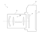
- the camera 1 includes a main body 2 and a photographing lens 3 mounted on the main body 2.
- the main body 2 includes an image sensor 4, a main body control unit (not shown) that controls the operation of a digital camera, and a liquid crystal screen 5.
- the photographing lens 3 includes an optical system OL composed of a plurality of lens groups and a lens position control mechanism (not shown) for controlling the position of each lens group.
- the lens position control mechanism includes a sensor that detects the position of the lens group, a motor that moves the lens group back and forth along the optical axis, a control circuit that drives the motor, and the like.
- the light from the subject is collected by the optical system OL of the photographing lens 3 and reaches the image plane I of the image pickup element 4.
- the light from the subject that has reached the image plane I is photoelectrically converted by the image pickup device 4 and recorded as digital image data in a memory (not shown).
- the digital image data recorded in the memory can be displayed on the liquid crystal screen 5 according to the operation of the user.
- This camera may be a mirrorless camera or a single-lens reflex type camera having a quick return mirror.
- the optical system OL shown in FIG. 22 schematically shows the optical system provided in the photographing lens 3, and the lens configuration of the optical system OL is not limited to this configuration.
- the optical system OL (1) as an example of the optical system OL according to the first embodiment has a front group GA and an aperture (aperture aperture) arranged in order from the object side along the optical axis. It is composed of S and the rear group GB.
- the rear group GB has a first focusing lens group GF1 having a negative refractive power arranged on the most object side of the rear group GB and a negative refractive power arranged on the image plane side of the first focusing lens group GF1.
- It has a second focusing lens group GF2 and the like.
- the first focusing lens group GF1 and the second focusing lens group GF2 move toward the image plane along the optical axis with different trajectories.
- each in-focus lens group can be made lighter, it is possible to obtain an optical system compatible with high-speed autofocus (AF). Since the drive mechanism of each in-focus lens group can be simplified, the sensitivity of optical performance to manufacturing errors can be suppressed.
- the optical system OL according to the first embodiment may be the variable magnification optical system OL (2) shown in FIG. 3, the optical system OL (3) shown in FIG. 5, or the optical system OL (4) shown in FIG. 7.
- the optical system OL (5) shown in FIG. 9 may be used.
- the optical system OL according to the first embodiment may be the variable magnification optical system OL (6) shown in FIG. 11, the optical system OL (7) shown in FIG. 13, and the optical system OL (10) shown in FIG. ) Is fine.
- the optical system OL according to the first embodiment satisfies the following conditional expression (1). 0.30 ⁇ STL / TL ⁇ 0.90 ... (1)
- STL the distance on the optical axis from the aperture S to the image plane I TL: the total length of the optical system OL.
- the conditional expression (1) defines an appropriate relationship between the distance on the optical axis from the aperture S to the image plane I and the total length of the optical system OL.
- the exit pupil position can be inferred, and an appropriate aperture position range can be defined.
- the total length of the optical system OL is the distance on the optical axis (air conversion distance) from the lens surface on the most object side of the optical system OL to the image plane I at the time of infinity focusing.
- the exit pupil becomes close to the image plane I, so that the tilt angle of the light beam incident on the image plane I becomes steep, and the angle of view changes due to a change in back focus due to a manufacturing error or the like. Fluctuations are likely to occur.
- the lower limit of the conditional expression (1) is set to 0.33, 0.35, 0.38, 0.40, 0.43, 0.45, 0.48, 0.50, and further 0.52. Therefore, the effect of this embodiment can be made more certain.
- the position of the aperture S is not appropriate, so that the ratio of the upper ray and the lower ray cut in the aperture S becomes unbalanced, resulting in a so-called one-sided aperture. Further, since the total length of the optical system OL is too short, it becomes difficult to correct the aberration.
- the upper limit of the conditional expression (1) to 0.88, 0.85, 0.83, 0.80, 0.78, and further 0.76, the effect of this embodiment is more reliable. Can be.
- the rear group GB has a positive lens group GP having a positive refractive power arranged between the first focusing lens group GF1 and the second focusing lens group GF2.
- the position of the positive lens group GP is fixed with respect to the image plane I. This makes it possible to satisfactorily correct spherical aberration, Petzval sum, and the like.
- the front group GA is composed of a leading lens group GA1 having a positive refractive power
- the rear group GB is a first focusing lens group GF1 and a second focusing lens group GF2.
- a positive lens group GP having a positive refractive power arranged between the lenses and a final lens group GE arranged on the image plane side of the second focusing lens group GF2.
- the optical system OL (1) as an example of the optical system OL according to the second embodiment is a preceding lens group GA1 having a positive refractive power arranged in order from the object side along the optical axis.
- each in-focus lens group can be made lighter, it is possible to obtain an optical system compatible with high-speed autofocus (AF). Since the drive mechanism of each in-focus lens group can be simplified, the sensitivity of optical performance to manufacturing errors can be suppressed.
- the optical system OL according to the second embodiment may be the variable magnification optical system OL (2) shown in FIG. 3, the optical system OL (3) shown in FIG. 5, or the optical system OL (4) shown in FIG. 7.
- the optical system OL (5) shown in FIG. 9 may be used.
- the optical system OL according to the second embodiment may be the variable magnification optical system OL (6) shown in FIG. 11, the optical system OL (7) shown in FIG. 13, and the optical system OL (8) shown in FIG. ), The optical system OL (9) shown in FIG. 17, or the optical system OL (10) shown in FIG.
- the aperture (aperture aperture) S is arranged between the preceding lens group GA1 and the first focusing lens group GF1.
- the light rays incident on the focusing lens group can be effectively narrowed down, and the focusing lens group can be made smaller and lighter.
- the optical system OL according to the second embodiment satisfies the above-mentioned conditional expression (1).
- the exit pupil position can be inferred and the range of the appropriate aperture position can be defined as in the first embodiment.
- the lower limit of the conditional expression (1) is set to 0.33, 0.35, 0.38, 0.40, 0.43, 0.45, 0.48, 0.50, and further 0.52. Therefore, the effect of this embodiment can be made more certain. Further, by setting the upper limit value of the conditional expression (1) to 0.88, 0.85, 0.83, 0.80, 0.78, and further 0.76, the effect of this embodiment is more reliable. Can be.
- the optical system OL according to the first embodiment and the second embodiment satisfies the following conditional expression (2). 0.50 ⁇ fA / f ⁇ 2.00 ... (2)
- fA focal length of the preceding lens group GA1
- f focal length of the optical system OL
- Conditional expression (2) defines an appropriate relationship between the focal length of the leading lens group GA1 and the focal length of the optical system OL.
- the lower limit of the conditional expression (2) is set to 0.55, 0.60, 0.65, 0.70, 0.75, 0.80, 0.85, 0.90, and further 0.95. Therefore, the effect of each embodiment can be made more certain.
- the upper limit of the conditional expression (2) is set to 1.90, 1.80, 1.75, 1.70, 1.65, 1.60, 1.55, 1.50, and further 1.45. By doing so, the effect of each embodiment can be made more certain.
- the optical system OL according to the first embodiment and the second embodiment satisfies the following conditional expression (3). 0.50 ⁇ fA / (-fF1) ⁇ 1.50 ... (3)
- fA focal length of the preceding lens group
- GA1 focal length of the first focusing lens group GF1.
- Conditional expression (3) defines an appropriate relationship between the focal length of the leading lens group GA1 and the focal length of the first focusing lens group GF1. By satisfying the conditional expression (3), it is possible to reduce aberration fluctuations and angle-of-view fluctuations during focusing.
- the lower limit of the conditional expression (3) is set to 0.53, 0.55, 0.58, 0.60, 0.63, 0.65, 0.58, 0.70, and further 0.73. Therefore, the effect of each embodiment can be made more certain. Further, by setting the upper limit value of the conditional expression (3) to 1.48, 1.45, 1.43, 1.40, 1.38, 1.35, and further 1.33, each embodiment can be set. The effect can be made more certain.
- the optical system OL according to the first embodiment and the second embodiment satisfies the following conditional expression (4). 0.35 ⁇ fB / (-fF1) ⁇ 1.50 ... (4)
- fB the combined focal length of the lens group arranged on the image plane side of the first in-focus lens group GF1
- fF1 the focal length of the first in-focus lens group GF1.
- Conditional expression (4) defines an appropriate relationship between the combined focal length of the lens group arranged on the image plane side of the first focusing lens group GF1 and the focal length of the first focusing lens group GF1. be.
- the lower limit of the conditional expression (4) is 0.38, 0.40, 0.43, 0.45, 0.48, 0.50, 0.53, 0.55, 0.58, and further 0.60. By setting to, the effect of each embodiment can be made more reliable. Further, the upper limit of the conditional expression (4) is set to 1.45, 1.40, 1.35, 1.30, 1.25, 1.20, 1.18, 1.20, 1.15, 1. 13. By further setting it to 1.10, the effect of each embodiment can be made more reliable.
- the optical system OL according to the first embodiment and the second embodiment satisfies the following conditional expression (5). -2.00 ⁇ (-fE) / f ⁇ 15.00 ... (5)
- fE focal length of the final lens group
- GE focal length of the optical system OL
- Conditional expression (5) defines an appropriate relationship between the focal length of the final lens group GE and the focal length of the optical system OL. By satisfying the conditional expression (5), shading can be suppressed and the total length of the optical system OL can be shortened.
- the lower limit of the conditional expression (5) is set to -1.80, -1.50, -1.00, -0.50, -0.10, 0.10, 0.50, 0.65, 0.80. Further, by setting it to 0.90, the effect of each embodiment can be further ensured. Further, the upper limit of the conditional expression (5) is set to 14.80, 12.00, 10.00, 8.50, 7.50, 6.00, 5.00, 4.50, and further 4.00. By doing so, the effect of each embodiment can be made more certain.
- the optical system OL according to the first embodiment and the second embodiment satisfies the following conditional expression (6). -1.00 ⁇ fP / (-fE) ⁇ 1.50 ... (6)
- fP focal length of the positive lens group
- GP focal length of the final lens group
- GE focal length of the final lens group
- Conditional expression (6) defines an appropriate relationship between the focal length of the positive lens group GP and the focal length of the final lens group GE.
- the lower limit of the conditional expression (6) is set to -0.80, -0.50, -0.25, -0.10, 0.01, 0.05, 0.12, and further 0.15. Therefore, the effect of each embodiment can be made more certain. Further, by setting the upper limit of the conditional expression (6) to 1.40, 1.25, 1.00, 0.85, 0.70, 0.65, 0.60, and further 0.55, The effect of each embodiment can be made more certain.
- the optical system OL according to the first embodiment and the second embodiment satisfies the following conditional expression (7). 1.10 ⁇ (-fF1) /fP ⁇ 3.20 ... (7)
- fF1 focal length of the first focusing lens group
- GF1 focal length of the positive lens group GP
- Conditional expression (7) defines an appropriate relationship between the focal length of the first focusing lens group GF1 and the focal length of the positive lens group GP.
- the lower limit of the conditional expression (7) is 1.15, 1.20, 1.25, 1.30, 1.33, 1.35, 1.38, 1.40, 1.43, and 1.45.
- the effect of each embodiment can be made more certain. Further, by setting the upper limit value of the conditional expression (7) to 3.15, 3.10, 3.05, and further 3.00, the effect of each embodiment can be further ensured.
- the optical system OL according to the first embodiment and the second embodiment satisfies the following conditional expression (8). 0.30 ⁇ fP / f ⁇ 1.00 ... (8)
- fP focal length of the positive lens group
- GP f focal length of the optical system OL
- Conditional expression (8) defines an appropriate relationship between the focal length of the positive lens group GP and the focal length of the optical system OL.
- conditional expression (8) If the corresponding value of the conditional expression (8) is out of the above range, it becomes difficult to correct spherical aberration, Petzval sum, and the like.
- the lower limit of the conditional expression (8) By setting the lower limit of the conditional expression (8) to 0.33, 0.35, 0.38, 0.40, and further 0.43, the effect of each embodiment can be further ensured. can.
- the upper limit value of the conditional expression (8) to 0.98, 0.95, 0.93, 0.90, and further 0.88, the effect of each embodiment is further ensured. be able to.
- the positive lens group GP is a negative lens, a first positive lens, and a second positive lens arranged in order from the object side along the optical axis. It is desirable to have. As a result, the optical system OL can be miniaturized, and the exit pupil can be made far from the image plane I. In addition, various aberrations such as spherical aberration can be satisfactorily corrected.
- the optical system OL according to the first embodiment and the second embodiment satisfies the following conditional expression (9). 0.10 ⁇ fF1 / fF2 ⁇ 2.00 ... (9)
- fF1 focal length of the first focusing lens group
- GF1 focal length of the second focusing lens group GF2
- Conditional expression (9) defines an appropriate relationship between the focal length of the first focusing lens group GF1 and the focal length of the second focusing lens group GF2. By satisfying the conditional expression (9), spherical aberration, curvature of field, and the like can be satisfactorily corrected.
- conditional expression (9) If the corresponding value of the conditional expression (9) is out of the above range, it becomes difficult to correct spherical aberration, curvature of field, and the like.
- the lower limit of the conditional expression (9) By setting the lower limit of the conditional expression (9) to 0.13, 0.15, 0.18, 0.20, 0.23, and further 0.25, the effect of each embodiment is more reliable.
- the upper limit of the conditional expression (9) is 1.98, 1.95, 1.93, 1.90, 1.75, 1.50, 1.40, 1.25, 1.10, and further 1. By setting it to .00, the effect of each embodiment can be made more reliable.
- the optical system OL according to the first embodiment and the second embodiment satisfies the following conditional expression (10). 0.50 ⁇ f / (-fF1) ⁇ 1.80 ... (10) However, f: focal length of the optical system OL fF1: focal length of the first focusing lens group GF1
- Conditional expression (10) defines an appropriate relationship between the focal length of the optical system OL and the focal length of the first focusing lens group GF1. By satisfying the conditional expression (10), chromatic aberration, curvature of field, and the like can be satisfactorily corrected.
- the lower limit of the conditional expression (10) is set to 0.53, 0.55, 0.58, 0.60, 0.63, 0.65, 0.68, 0.70, 0.73, and further 0.75. By setting to, the effect of each embodiment can be made more reliable. Further, by setting the upper limit value of the conditional expression (10) to 1.78, 1.75, 1.73, 1.70, 1.50, 1.40, and further 1.20, each embodiment can be set. The effect can be made more certain.
- the first focusing lens group GF1 is composed of one negative lens component.
- the first focusing lens group GF1 becomes lightweight, so that it is possible to focus from an infinity object to a short-distance object at high speed.
- the lens component indicates a single lens or a junction lens.
- the optical system OL according to the first embodiment and the second embodiment satisfies the following conditional expression (11). -2.50 ⁇ (rF12 + rF11) / (rF12-rF11) ⁇ 0.00 ... (11)
- rF11 the radius of curvature of the lens surface on the most object side in the first focusing lens group GF1
- rF12 the radius of curvature of the lens surface on the most image plane side in the first focusing lens group GF1.
- the conditional expression (11) defines an appropriate range for the shape factor of the lenses constituting the first focusing lens group GF1. By satisfying the conditional expression (11), spherical aberration, coma aberration and the like can be satisfactorily corrected.
- conditional expression (11) If the corresponding value of the conditional expression (11) is out of the above range, it becomes difficult to correct spherical aberration, coma aberration, and the like.
- the lower limit of the conditional expression (11) By setting the lower limit of the conditional expression (11) to -2.45, -2.40, -2.35, -2.30, -2.28, -2.25, and further -2.23. , The effect of each embodiment can be made more certain.
- the upper limit of the conditional expression (11) is set to -0.05, -0.10, -0.15, -0.20, -0.25, -0.30, -0.35, -0. By setting it to 40, ⁇ 0.45, ⁇ 0.50, and further ⁇ 0.55, the effect of each embodiment can be further ensured.
- the second focusing lens group GF2 is composed of one negative lens component.
- the second focusing lens group GF2 becomes lightweight, so that it is possible to focus from an infinity object to a short-distance object at high speed.
- the optical system OL according to the first embodiment and the second embodiment satisfies the following conditional expression (12). 0.05 ⁇ Bf / TL ⁇ 0.80 ... (12) However, Bf: back focus of the optical system OL TL: total length of the optical system OL
- Conditional expression (12) defines an appropriate relationship between the back focus of the optical system OL and the total length of the optical system OL. By satisfying the conditional expression (12), spherical aberration, coma aberration and the like can be satisfactorily corrected.
- the back focus of the optical system OL is the distance (air conversion distance) on the optical axis from the lens surface on the most image plane side of the optical system OL to the image plane I at the time of infinity focusing. ..
- the exit pupil becomes too close to the image plane I, so that light beam vignetting occurs on the image plane I. Attempting to avoid this may result in difficulty in correcting aberrations other than the axis, particularly coma, which is not preferable.
- the lower limit of the conditional expression (12) By setting the lower limit of the conditional expression (12) to 0.06 and further to 0.07, the effect of each embodiment can be further ensured.
- the corresponding value of the conditional expression (12) exceeds the upper limit value, the total length of the optical system OL is too short, and it becomes difficult to correct spherical aberration, coma aberration, and the like. Further, since the back focus of the optical system OL is too long, the optical system OL becomes large.
- Each implementation is carried out by setting the upper limit of the conditional expression (12) to 0.75, 0.70, 0.65, 0.50, 0.40, 0.35, 0.30, and further 0.25. The effect of the morphology can be made more certain.
- the optical system OL according to the first embodiment and the second embodiment satisfies the following conditional expression (13). -0.80 ⁇ (rR2 + rR1) / (rR2-rR1) ⁇ 2.50 ... (13)
- rR1 radius of curvature of the lens surface on the object side of the lens arranged on the most image plane side of the optical system OL
- rR2 curvature of the lens surface on the image plane side of the lens arranged on the most image plane side of the optical system OL. radius
- Conditional expression (13) defines an appropriate range for the shape factor of the lens arranged on the most image plane side of the optical system OL.
- the lower limit of the conditional expression (13) is set to -0.75, -0.70, -0.65, -0.60, -0.50, -0.30, 0.30, 0.50, 0. By setting it to 80 and further to 0.95, the effect of each embodiment can be further ensured. Further, by setting the upper limit value of the conditional expression (13) to 2.45, 2.35, 2.15, 2.00, 1.85, and further 1.70, the effect of each embodiment is more reliable. Can be.
- the optical system OL according to the first embodiment and the second embodiment satisfies the following conditional expression (14). 0.01 ⁇ 1 / ⁇ F1 ⁇ 0.60 ... (14) However, ⁇ F1: lateral magnification of the first focusing lens group GF1 when focusing on an infinity object.
- Conditional expression (14) defines an appropriate range for the lateral magnification of the first focusing lens group GF1 when focusing on an infinity object.
- various aberrations such as spherical aberration and curvature of field at the time of focusing on an infinity object can be satisfactorily corrected.
- conditional expression (14) If the corresponding value of the conditional expression (14) is out of the above range, it becomes difficult to correct various aberrations such as spherical aberration and curvature of field when focusing on an infinite object.
- the lower limit of the conditional expression (14) By setting the lower limit of the conditional expression (14) to 0.02, 0.05, and further 0.08, the effect of each embodiment can be further ensured.
- the upper limit value of the conditional expression (14) to 0.58, 0.55, 0.53, 0.50, 0.48, 0.45, and further 0.43, each embodiment can be set. The effect can be made more certain.
- the optical system OL according to the first embodiment and the second embodiment satisfies the following conditional expression (15). 0.50 ⁇ 1 / ⁇ F2 ⁇ 0.95 ... (15)
- ⁇ F2 lateral magnification of the second focusing lens group GF2 when focusing on an infinity object.
- Conditional expression (15) defines an appropriate range for the lateral magnification of the second focusing lens group GF2 when focusing on an infinity object.
- various aberrations such as spherical aberration and curvature of field at the time of focusing on an infinity object can be satisfactorily corrected.
- conditional expression (15) If the corresponding value of the conditional expression (15) is out of the above range, it becomes difficult to correct various aberrations such as spherical aberration and curvature of field at the time of focusing on an infinity object.
- the lower limit of the conditional expression (15) By setting the lower limit of the conditional expression (15) to 0.53, 0.55, 0.58, and further 0.60, the effect of each embodiment can be further ensured.
- the upper limit value of the conditional expression (15) to 0.94, 0.92, 0.90, and further 0.85, the effect of each embodiment can be further ensured.
- the optical system OL according to the first embodiment and the second embodiment satisfies the following conditional expression (16).
- ⁇ F1 lateral magnification of the first focusing lens group GF1 when focusing on an infinity object.
- Conditional expression (16) defines an appropriate range for the lateral magnification of the first focusing lens group GF1 when focusing on an infinity object.
- various aberrations such as spherical aberration and curvature of field at the time of focusing on an infinity object can be satisfactorily corrected.
- conditional expression (16) If the corresponding value of the conditional expression (16) is out of the above range, it becomes difficult to correct various aberrations such as spherical aberration and curvature of field at the time of focusing on an infinity object.
- the upper limit of the conditional expression (16) By setting the upper limit of the conditional expression (16) to 0.18, 0.16, 0.15, and further 0.14, the effect of each embodiment can be further ensured.
- the optical system OL according to the first embodiment and the second embodiment satisfies the following conditional expression (17).
- ⁇ F2 lateral magnification of the second focusing lens group GF2 when focusing on an infinity object.
- Conditional expression (17) defines an appropriate range for the lateral magnification of the second focusing lens group GF2 when focusing on an infinity object.
- various aberrations such as spherical aberration and curvature of field at the time of focusing on an infinity object can be satisfactorily corrected. If the corresponding value of the conditional expression (17) is out of the above range, it becomes difficult to correct various aberrations such as spherical aberration and curvature of field at the time of focusing on an infinity object.
- the optical system OL according to the first embodiment and the second embodiment satisfies the following conditional expression (18). 0.15 ⁇ MF1 / MF2 ⁇ 0.80 ... (18)
- MF1 absolute value of the amount of movement of the first focusing lens group GF1 when focusing from an infinite object to a short-distance object
- MF2 a second focusing lens when focusing from an infinite object to a short-distance object. Absolute value of movement of group GF2
- Conditional expression (18) defines an appropriate relationship between the amount of movement of the first focusing lens group GF1 and the amount of movement of the second focusing lens group GF2 when focusing from an infinite object to a short-range object. It is something to do.
- spherical aberration, coma aberration, curvature of field, and the like can be satisfactorily corrected.
- conditional expression (18) If the corresponding value of the conditional expression (18) is out of the above range, it becomes difficult to correct spherical aberration, coma aberration, curvature of field, and the like.
- the lower limit of the conditional expression (18) By setting the lower limit of the conditional expression (18) to 0.16, 0.18, 0.20, and further 0.22, the effect of each embodiment can be further ensured. Further, by setting the upper limit value of the conditional expression (18) to 0.78, 0.75, 0.73, 0.70, and further 0.68, the effect of each embodiment is further ensured. be able to.
- the optical system OL according to the first embodiment and the second embodiment satisfies the following conditional expression (19). 20.00 ° ⁇ 2 ⁇ ⁇ 40.00 ° ⁇ ⁇ ⁇ (19) However, 2 ⁇ : the total angle of view of the optical system OL
- Conditional expression (19) defines an appropriate range for the entire angle of view of the optical system OL. Satisfying the conditional expression (19) is preferable because an optical system having a wide angle of view can be obtained.
- the lower limit of the conditional expression (19) By setting the lower limit of the conditional expression (19) to 22.00 °, 24.00 °, 26.00 °, and further 27.00 °, the effect of each embodiment can be further ensured. can. Further, by setting the upper limit value of the conditional expression (19) to 38.00 °, 37.00 °, and further 36.00 °, the effect of each embodiment can be further ensured.
- the optical system OL according to the first embodiment and the second embodiment satisfies the following conditional expression (20). 0.08 ⁇ Bf / f ⁇ 1.20 ... (20) However, Bf: back focus of the optical system OL f: focal length of the optical system OL
- Conditional expression (20) defines an appropriate relationship between the back focus of the optical system OL and the focal length of the optical system OL. By satisfying the conditional expression (20), it is possible to obtain an optical system having a short back focus while satisfactorily suppressing the occurrence of various aberrations. By setting the lower limit of the conditional expression (20) to 0.09, 0.10, 0.11, and further 0.12, the effect of each embodiment can be further ensured. Further, by setting the upper limit value of the conditional expression (20) to 1.18, 1.15, 1.13, 1.10, 1.08, 1.05, and further 1.03, each embodiment can be set. The effect can be made more certain.
- the manufacturing method of the optical system OL according to the first embodiment will be outlined.
- the front group GA, the aperture (opening aperture) S, and the rear group GB are arranged in order from the object side along the optical axis (step ST1).
- the first focusing lens group GF1 having a negative refractive power is arranged on the most object side of the rear group GB, and has a negative refractive power on the image plane side of the first focusing lens group GF1 of the rear group GB.
- the second focusing lens group GF2 is arranged (step ST2).
- the first focusing lens group GF1 and the second focusing lens group GF2 move toward the image plane along the optical axis with different trajectories.
- Each lens is arranged in the lens barrel (step ST3). According to such a manufacturing method, it becomes possible to manufacture an optical system having less aberration fluctuation during focusing.
- the manufacturing method of the optical system OL according to the second embodiment will be outlined.
- the second focusing lens group GF2 having a negative refractive power and the final lens group GE are arranged (step ST11).
- the first focusing lens group GF1 and the second focusing lens group GF2 move toward the image plane along the optical axis with different trajectories.
- Each lens is arranged in the lens barrel (step ST12). According to such a manufacturing method, it becomes possible to manufacture an optical system having less aberration fluctuation during focusing.
- FIG. 3 are optical systems OL ⁇ OL (1) to OL according to the first to tenth embodiments. It is sectional drawing which shows the structure of (10) ⁇ and the refractive power distribution.
- the moving direction along the optical axis of each lens group when focusing on a short-range object from infinity is indicated by an arrow. Shows.
- the moving direction along the optical axis of each lens group when scaling from the wide-angle end state (W) to the telephoto end state (T) is indicated by an arrow. Shows.
- each lens group is divided into each lens by a combination of the reference numerals G and numbers.
- the lens group and the like are represented by independently using combinations of the reference numerals and numbers for each embodiment. Therefore, even if the same combination of reference numerals and numbers is used between the examples, it does not mean that they have the same configuration.
- Tables 1 to 10 are shown below, of which Table 1 is the first embodiment, Table 2 is the second embodiment, Table 3 is the third embodiment, Table 4 is the fourth embodiment, and Table 5 is the first embodiment.
- Table 6 shows the 6th Example
- Table 7 shows the 7th Example
- Table 8 shows the 8th Example
- Table 9 shows the 9th Example
- Table 10 shows the specification data in the 10th Example. It is a table.
- f is the focal length of the entire lens system
- FNO is the F number
- 2 ⁇ is the angle of view (unit is ° (degrees)
- ⁇ is the half angle of view
- Y is the image height.
- TL indicates the distance from the frontmost surface of the lens to the final surface of the lens on the optical axis at infinity, plus Bf
- Bf is the image from the final surface of the lens on the optical axis at infinity.
- the distance to the surface I (back focus) is shown.
- TL (a) indicates the distance (air equivalent distance) on the optical axis from the lens surface on the most object side of the optical system to the image plane I at the time of focusing at infinity.
- Bf (a) indicates the distance (air equivalent distance) on the optical axis from the lens surface on the image plane side of the optical system to the image plane I at the time of infinity focusing.
- W wide-angle end
- M intermediate focal length
- T telephoto end
- fA indicates the focal length of the preceding lens group.
- fB indicates the combined focal length of the lens group arranged on the image plane side of the first focusing lens group.
- ⁇ F1 indicates the lateral magnification of the first focusing lens group at the time of focusing on an infinity object.
- ⁇ F2 indicates the lateral magnification of the second focusing lens group at the time of focusing on an infinity object.
- MF1 indicates the absolute value of the amount of movement of the first focusing lens group when focusing from an infinite object to a short-distance object.
- MF2 indicates the absolute value of the amount of movement of the second focusing lens group when focusing from an infinite object to a short-distance object.
- the plane numbers indicate the order of the optical planes from the object side along the traveling direction of the light beam
- R is the radius of curvature of each optical plane (the plane whose center of curvature is located on the image side).
- D is the distance on the optical axis from each optical surface to the next optical surface (or image surface)
- nd is the refractive index of the material of the optical member with respect to the d line
- ⁇ d is optical.
- the Abbe numbers based on the d-line of the material of the member are shown. “ ⁇ ” of the radius of curvature indicates a plane or an opening, and (aperture S) indicates an opening aperture S.
- the description of the refractive index nd of air 1.00000 is omitted.
- the table of [Variable spacing data] shows the surface spacing at the surface number i in which the surface spacing is (Di) in the table of [Lens specifications].
- f indicates the focal length of the entire lens system
- ⁇ indicates the photographing magnification.
- D0 indicates the distance from the object to the optical surface on the most object side in the optical system.
- [Variable Interval Data] table [lenses] corresponding to the wide-angle end (W), intermediate focal length (M), and telephoto end (T) magnification states.
- W wide-angle end
- M intermediate focal length
- T telephoto end
- the table of [lens group data] shows the starting surface (the surface closest to the object) and the focal length of each lens group.
- mm is generally used for the focal length f, the radius of curvature R, the plane spacing D, other lengths, etc., unless otherwise specified, but the optical system is expanded proportionally.
- the optical performance is not limited to this because the same optical performance can be obtained even if the proportional reduction is performed.
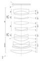
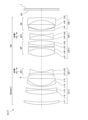
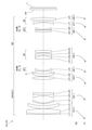
- FIG. 1 is a diagram showing a lens configuration of an optical system according to the first embodiment.
- the optical system OL (1) according to the first embodiment has a first lens group G1 having a positive refractive power and a second lens group G2 having a negative power, which are arranged in order from the object side along the optical axis. It is composed of a third lens group G3 having a positive refractive power, a fourth lens group G4 having a negative refractive power, and a fifth lens group G5 having a negative refractive power.
- the second lens group G2 and the fourth lens group G4 move toward the image side along the optical axis with different trajectories (movement amounts), and adjacent lenses move to the image side.
- the spacing of the groups changes.
- the positions of the first lens group G1, the third lens group G3, and the fifth lens group G5 are fixed with respect to the image plane I.
- the symbol (+) or ( ⁇ ) attached to each lens group symbol indicates the refractive power of each lens group, and this also applies to all the following examples.
- the aperture stop S is arranged between the first lens group G1 and the second lens group G2. At the time of focusing, the position of the aperture stop S is fixed with respect to the image plane I.
- the first lens group G1 constitutes the front group GA
- the second lens group G2 corresponds to the first in-focus lens group GF1
- the third lens group G3 corresponds to the positive lens group GP
- the fourth lens corresponds to the second in-focus lens group GF2
- the fifth lens group G5 corresponds to the final lens group GE.
- the first lens group G1 has a positive meniscus lens L11 having a convex surface facing the object side, a regular meniscus lens L12 having a convex surface facing the object side, and a convex surface toward the object side, which are arranged in order from the object side along the optical axis.
- the second lens group G2 is composed of a negative meniscus lens L21 having a convex surface facing the object side.
- the third lens group G3 includes a junction lens in which a biconcave negative lens L31 and a biconvex positive lens L32 are joined in order from the object side along the optical axis, and a biconvex positive lens L33. And a biconvex positive lens L34.
- the fourth lens group G4 is composed of a negative lens L41 having a biconcave shape.
- the fifth lens group G5 includes a bonded lens in which a biconvex positive lens L51 arranged in order from the object side along the optical axis and a negative meniscus lens L52 having a concave surface facing the object side are joined, and a bonded lens on the object side. It is composed of a negative meniscus lens L53 with a concave surface facing.
- the image plane I is arranged on the image side of the fifth lens group G5.
- a parallel flat plate PP is arranged between the fifth lens group G5 and the image plane I.
- Table 1 below lists the values of the specifications of the optical system according to the first embodiment.
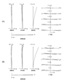
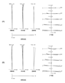
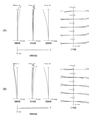
- FIG. 2A is a diagram of various aberrations of the optical system according to the first embodiment at the time of infinity focusing.
- FIG. 2B is a diagram of various aberrations of the optical system according to the first embodiment at the time of short-distance focusing.
- FNO indicates an F number
- Y indicates an image height.
- NA indicates the numerical aperture
- Y indicates the image height.
- the spherical aberration diagram shows the value of the F number or numerical aperture corresponding to the maximum aperture
- the astigmatism diagram and the distortion diagram show the maximum image height
- the coma aberration diagram shows the value of each image height. ..
- the solid line shows the sagittal image plane and the broken line shows the meridional image plane.
- the optical system according to the first embodiment has excellent imaging performance in which various aberrations are satisfactorily corrected in the entire range from infinity focusing to short-distance focusing. You can see that.
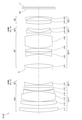
- FIG. 3 is a diagram showing a lens configuration of an optical system according to a second embodiment.
- the optical system OL (2) according to the second embodiment has a first lens group G1 having a positive refractive power and a second lens group G2 having a negative power, which are arranged in order from the object side along the optical axis. It is composed of a third lens group G3 having a positive refractive power, a fourth lens group G4 having a negative refractive power, and a fifth lens group G5 having a negative refractive power.
- the second lens group G2 and the fourth lens group G4 move toward the image side along the optical axis with different trajectories (movement amounts), and adjacent lenses move to the image side.
- the spacing of the groups changes.
- the positions of the first lens group G1, the third lens group G3, and the fifth lens group G5 are fixed with respect to the image plane I.
- the aperture stop S is arranged between the first lens group G1 and the second lens group G2. At the time of focusing, the position of the aperture stop S is fixed with respect to the image plane I.
- the first lens group G1 constitutes the front group GA
- the second lens group G2 corresponds to the first in-focus lens group GF1
- the third lens group G3 corresponds to the positive lens group GP
- the fourth lens corresponds to the second in-focus lens group GF2
- the fifth lens group G5 corresponds to the final lens group GE.
- the first lens group G1 has a positive meniscus lens L11 having a convex surface facing the object side, a regular meniscus lens L12 having a convex surface facing the object side, and a biconvex positive lens arranged in order from the object side along the optical axis. It is composed of a bonded lens in which a lens L13 and a biconcave negative lens L14 are bonded, and a positive meniscus lens L15 having a convex surface facing the object side.
- the second lens group G2 is composed of a negative meniscus lens L21 having a convex surface facing the object side.
- the third lens group G3 is a bonded lens in which a negative meniscus lens L31 having a convex surface facing the object side and a positive meniscus lens L32 having a convex surface facing the object side are joined in order from the object side along the optical axis.
- the fourth lens group G4 is composed of a negative meniscus lens L41 having a convex surface facing the object side.
- the fifth lens group G5 is composed of a positive meniscus lens L51 having a convex surface facing the object side and a negative meniscus lens L52 having a concave surface facing the object side, which are arranged in order from the object side along the optical axis.
- the image plane I is arranged on the image side of the fifth lens group G5.
- a parallel flat plate PP is arranged between the fifth lens group G5 and the image plane I.
- Table 2 below lists the values of the specifications of the optical system according to the second embodiment.
- FIG. 4A is a diagram of various aberrations of the optical system according to the second embodiment at infinity focusing.
- FIG. 4B is a diagram of various aberrations of the optical system according to the second embodiment at the time of short-distance focusing. From each aberration diagram, the optical system according to the second embodiment has excellent imaging performance in which various aberrations are satisfactorily corrected in the entire range from infinity focusing to short-distance focusing. You can see that.
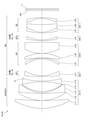
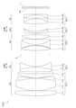
- FIG. 5 is a diagram showing a lens configuration of an optical system according to a third embodiment.
- the optical system OL (3) according to the third embodiment has a first lens group G1 having a positive refractive power and a second lens group G2 having a negative power, which are arranged in order from the object side along the optical axis. It is composed of a third lens group G3 having a positive refractive power, a fourth lens group G4 having a negative refractive power, and a fifth lens group G5 having a negative refractive power.
- the second lens group G2 and the fourth lens group G4 move toward the image side along the optical axis with different trajectories (movement amounts), and adjacent lenses move to the image side.
- the spacing of the groups changes.
- the positions of the first lens group G1, the third lens group G3, and the fifth lens group G5 are fixed with respect to the image plane I.
- the aperture stop S is arranged between the first lens group G1 and the second lens group G2. At the time of focusing, the position of the aperture stop S is fixed with respect to the image plane I.
- the first lens group G1 constitutes the front group GA
- the second lens group G2, the third lens group G3, the fourth lens group G4, and the fifth lens group G5 form the rear group GB.
- the first lens group G1 corresponds to the preceding lens group GA1
- the second lens group G2 corresponds to the first in-focus lens group GF1
- the third lens group G3 corresponds to the positive lens group GP
- the fourth lens corresponds to the second in-focus lens group GF2
- the fifth lens group G5 corresponds to the final lens group GE.
- the first lens group G1 includes a positive meniscus lens L11 having a convex surface facing the object side, a regular meniscus lens L12 having a convex surface facing the object side, and a biconvex positive lens, which are arranged in order from the object side along the optical axis. It is composed of a bonded lens in which a lens L13 and a biconcave negative lens L14 are bonded.
- the second lens group G2 is composed of a negative meniscus lens L21 having a convex surface facing the object side.
- the third lens group G3 is composed of a biconvex positive lens L31.
- the fourth lens group G4 is composed of a negative meniscus lens L41 having a convex surface facing the object side.
- the fifth lens group G5 is composed of a positive meniscus lens L51 having a convex surface facing the object side and a negative meniscus lens L52 having a concave surface facing the object side, which are arranged in order from the object side along the optical axis.
- the image plane I is arranged on the image side of the fifth lens group G5.
- a parallel flat plate PP is arranged between the fifth lens group G5 and the image plane I.
- Table 3 below lists the values of the specifications of the optical system according to the third embodiment.
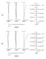
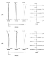
- FIG. 6A is a diagram of various aberrations of the optical system according to the third embodiment at the time of infinity focusing.
- FIG. 6B is a diagram of various aberrations of the optical system according to the third embodiment at the time of short-distance focusing. From each aberration diagram, the optical system according to the third embodiment has excellent imaging performance in which various aberrations are satisfactorily corrected in the entire range from infinity focusing to short-distance focusing. You can see that.
- FIG. 7 is a diagram showing a lens configuration of an optical system according to a fourth embodiment.
- the optical system OL (4) according to the fourth embodiment has a first lens group G1 having a positive refractive power and a second lens group G2 having a negative power, which are arranged in order from the object side along the optical axis. It is composed of a third lens group G3 having a positive refractive power, a fourth lens group G4 having a negative refractive power, and a fifth lens group G5 having a negative refractive power.
- the second lens group G2 and the fourth lens group G4 move toward the image side along the optical axis with different trajectories (movement amounts), and adjacent lenses move to the image side.
- the spacing of the groups changes.
- the positions of the first lens group G1, the third lens group G3, and the fifth lens group G5 are fixed with respect to the image plane I.
- the aperture stop S is arranged between the first lens group G1 and the second lens group G2. At the time of focusing, the position of the aperture stop S is fixed with respect to the image plane I.
- the first lens group G1 constitutes the front group GA
- the second lens group G2 corresponds to the first in-focus lens group GF1
- the third lens group G3 corresponds to the positive lens group GP
- the fourth lens corresponds to the second in-focus lens group GF2
- the fifth lens group G5 corresponds to the final lens group GE.
- the first lens group G1 includes a positive meniscus lens L11 having a convex surface facing the object side, a regular meniscus lens L12 having a convex surface facing the object side, and a convex surface facing the object side, which are arranged in order from the object side along the optical axis. It is composed of a bonded lens to which a negative meniscus lens L13 is bonded and a bonded lens to which a biconvex positive lens L14 and a biconcave negative lens L15 are bonded.
- the second lens group G2 is composed of a negative meniscus lens L21 having a convex surface facing the object side.
- the third lens group G3 includes a negative meniscus lens L31 having a concave surface facing the object side, a positive meniscus lens L32 having a concave surface facing the object side, and a biconvex positive lens arranged in order from the object side along the optical axis. It is composed of a lens L33.
- the fourth lens group G4 is composed of a negative meniscus lens L41 having a convex surface facing the object side.
- the fifth lens group G5 has a negative meniscus lens L51 having a convex surface facing the object side, a positive meniscus lens L52 having a convex surface facing the object side, and a concave surface facing the object side, arranged in order from the object side along the optical axis. It is composed of a negative meniscus lens L53 directed toward the object.
- the image plane I is arranged on the image side of the fifth lens group G5.
- a parallel flat plate PP is arranged between the fifth lens group G5 and the image plane I.
- Table 4 lists the values of the specifications of the optical system according to the fourth embodiment.
- FIG. 8A is a diagram of various aberrations of the optical system according to the fourth embodiment at the time of infinity focusing.
- FIG. 8B is a diagram of various aberrations of the optical system according to the fourth embodiment at the time of short-distance focusing. From each aberration diagram, the optical system according to the fourth embodiment has excellent imaging performance in which various aberrations are satisfactorily corrected in the entire range from infinity focusing to short-distance focusing. You can see that.
- FIG. 9 is a diagram showing a lens configuration of an optical system according to a fifth embodiment.
- the optical system OL (5) according to the fifth embodiment has a first lens group G1 having a positive refractive power and a second lens group G2 having a negative power, which are arranged in order from the object side along the optical axis. It is composed of a third lens group G3 having a positive refractive power, a fourth lens group G4 having a negative refractive power, and a fifth lens group G5 having a negative refractive power.
- the second lens group G2 and the fourth lens group G4 move toward the image side along the optical axis with different trajectories (movement amounts), and adjacent lenses move to the image side.
- the spacing of the groups changes.
- the positions of the first lens group G1, the third lens group G3, and the fifth lens group G5 are fixed with respect to the image plane I.
- the aperture stop S is arranged between the first lens group G1 and the second lens group G2. At the time of focusing, the position of the aperture stop S is fixed with respect to the image plane I.
- the first lens group G1 constitutes the front group GA
- the second lens group G2 corresponds to the first in-focus lens group GF1
- the third lens group G3 corresponds to the positive lens group GP
- the fourth lens corresponds to the second in-focus lens group GF2
- the fifth lens group G5 corresponds to the final lens group GE.
- a positive meniscus lens L11 having a convex surface facing the object side arranged in order from the object side along the optical axis, a biconvex positive lens L12, and a biconcave negative lens L13 are joined. It is composed of a bonded lens, and a bonded lens in which a negative meniscus lens L14 having a convex surface facing the object side and a positive meniscus lens L15 having a convex surface facing the object side are bonded.
- the second lens group G2 is composed of a bonded lens having a negative refractive power, in which a positive meniscus lens L21 having a concave surface facing the object side and a biconcave negative lens L22 are joined in order from the object side.
- the third lens group G3 is composed of a biconvex positive lens L31 arranged in order from the object side along the optical axis, and a negative meniscus lens L32 with a concave surface facing the object side.
- the fourth lens group G4 is composed of a bonded lens having a negative refractive power in which a biconvex positive lens L41 and a biconcave negative lens L42 are joined in order from the object side.
- the fifth lens group G5 includes a bonded lens in which a negative meniscus lens L51 having a convex surface facing the object side and a biconvex positive lens L52, which are arranged in order from the object side along the optical axis, and a bonded lens on the object side. It is composed of a negative meniscus lens L53 with a concave surface facing.
- the image plane I is arranged on the image side of the fifth lens group G5.
- a parallel flat plate PP is arranged between the fifth lens group G5 and the image plane I.
- Table 5 lists the values of the specifications of the optical system according to the fifth embodiment.
- FIG. 10A is a diagram of various aberrations of the optical system according to the fifth embodiment at the time of infinity focusing.
- FIG. 10B is a diagram of various aberrations of the optical system according to the fifth embodiment at the time of short-distance focusing. From each aberration diagram, the optical system according to the fifth embodiment has excellent imaging performance in which various aberrations are satisfactorily corrected in the entire range from infinity focusing to short-distance focusing. You can see that.
- FIG. 11 is a diagram showing a lens configuration of an optical system according to a sixth embodiment.
- the first lens group G1 having a positive refractive power and the second lens group G2 having a negative refractive power arranged in order from the object side along the optical axis. It is composed of a third lens group G3 having a positive refractive power, a fourth lens group G4 having a negative refractive power, and a fifth lens group G5 having a negative refractive power.
- the second lens group G2 and the fourth lens group G4 move toward the image side along the optical axis with different trajectories (movement amounts), and adjacent lenses move to the image side.
- the spacing of the groups changes.
- the positions of the first lens group G1, the third lens group G3, and the fifth lens group G5 are fixed with respect to the image plane I.
- the aperture stop S is arranged between the first lens group G1 and the second lens group G2. At the time of focusing, the position of the aperture stop S is fixed with respect to the image plane I.
- the first lens group G1 constitutes the front group GA
- the second lens group G2, the third lens group G3, the fourth lens group G4, and the fifth lens group G5 form the rear group GB.
- the first lens group G1 corresponds to the preceding lens group GA1
- the second lens group G2 corresponds to the first in-focus lens group GF1
- the third lens group G3 corresponds to the positive lens group GP
- the fourth lens corresponds to the second in-focus lens group GF2
- the fifth lens group G5 corresponds to the final lens group GE.
- the first lens group G1 has a positive meniscus lens L11 having a convex surface facing the object side, a regular meniscus lens L12 having a convex surface facing the object side, and a convex surface toward the object side, which are arranged in order from the object side along the optical axis.
- the second lens group G2 is composed of a bonded lens having a negative refractive power in which a negative meniscus lens L21 having a convex surface facing the object side and a negative meniscus lens L22 having a convex surface facing the object side are joined in order from the object side. Will be done.
- the third lens group G3 consists of a bonded lens in which a biconcave negative lens L31 and a biconvex positive lens L32 are joined in order from the object side along the optical axis, and a convex surface is directed toward the object side. It is composed of a positive meniscus lens L33 and a biconvex positive lens L34.
- the fourth lens group G4 is composed of a negative meniscus lens L41 having a convex surface facing the object side.
- the fifth lens group G5 includes a bonded lens in which a biconvex positive lens L51 arranged in order from the object side along the optical axis and a negative meniscus lens L52 having a concave surface facing the object side are joined, and a bonded lens on the object side. It is composed of a negative meniscus lens L53 with a concave surface facing.
- the image plane I is arranged on the image side of the fifth lens group G5.
- a parallel flat plate PP is arranged between the fifth lens group G5 and the image plane I.
- Table 6 lists the values of the specifications of the optical system according to the sixth embodiment.
- FIG. 12A is a diagram of various aberrations of the optical system according to the sixth embodiment at infinity focusing.
- FIG. 12B is a diagram of various aberrations of the optical system according to the sixth embodiment at the time of short-distance focusing. From each aberration diagram, the optical system according to the sixth embodiment has excellent imaging performance in which various aberrations are satisfactorily corrected in the entire range from infinity focusing to short-distance focusing. You can see that.
- FIG. 13 is a diagram showing a lens configuration of an optical system according to a seventh embodiment.
- the optical system OL (7) according to the seventh embodiment has a first lens group G1 having a positive refractive power and a second lens group G2 having a negative power, which are arranged in order from the object side along the optical axis. It is composed of a third lens group G3 having a positive refractive power, a fourth lens group G4 having a negative refractive power, and a fifth lens group G5 having a negative refractive power.
- the second lens group G2 and the fourth lens group G4 move toward the image side along the optical axis with different trajectories (movement amounts), and adjacent lenses move to the image side.
- the spacing of the groups changes.
- the positions of the first lens group G1, the third lens group G3, and the fifth lens group G5 are fixed with respect to the image plane I.
- the aperture stop S is arranged between the first lens group G1 and the second lens group G2. At the time of focusing, the position of the aperture stop S is fixed with respect to the image plane I.
- the first lens group G1 constitutes the front group GA
- the second lens group G2, the third lens group G3, the fourth lens group G4, and the fifth lens group G5 form the rear group GB.
- the first lens group G1 corresponds to the preceding lens group GA1
- the second lens group G2 corresponds to the first in-focus lens group GF1
- the third lens group G3 corresponds to the positive lens group GP
- the fourth lens corresponds to the second in-focus lens group GF2
- the fifth lens group G5 corresponds to the final lens group GE.
- a positive meniscus lens L11 having a convex surface facing the object side arranged in order from the object side along the optical axis, a biconvex positive lens L12, and a biconcave negative lens L13 are joined. It is composed of a bonded lens, and a bonded lens in which a negative meniscus lens L14 having a convex surface facing the object side and a positive meniscus lens L15 having a convex surface facing the object side are bonded.
- the second lens group G2 is composed of a bonded lens having a negative refractive power, in which a positive meniscus lens L21 having a concave surface facing the object side and a biconcave negative lens L22 are joined in order from the object side.
- the third lens group G3 is a bonded lens in which a biconvex positive lens L31 arranged in order from the object side along the optical axis and a negative meniscus lens having a concave surface facing the object side are joined, and a convex surface on the object side. It is composed of a bonded lens in which a negative meniscus lens L33 facing the lens and a biconvex positive lens L34 are bonded.
- the fourth lens group G4 is composed of a bonded lens having a negative refractive power, in which a positive meniscus lens L41 having a concave surface facing the object side and a biconcave negative lens L42 are bonded in order from the object side.
- the fifth lens group G5 includes a negative meniscus lens L51 having a convex surface facing the object side, a biconvex positive lens L52, and a negative meniscus having a concave surface facing the object side, arranged in order from the object side along the optical axis. It is composed of a lens L53.
- the image plane I is arranged on the image side of the fifth lens group G5.
- a parallel flat plate PP is arranged between the fifth lens group G5 and the image plane I.
- Table 7 lists the values of the specifications of the optical system according to the seventh embodiment.
- FIG. 14A is a diagram of various aberrations of the optical system according to the seventh embodiment at the time of infinity focusing.
- FIG. 14B is a diagram of various aberrations of the optical system according to the seventh embodiment during short-distance focusing. From each aberration diagram, the optical system according to the seventh embodiment has excellent imaging performance in which various aberrations are satisfactorily corrected in the entire range from infinity focusing to short-distance focusing. You can see that.
- FIG. 15 is a diagram showing a lens configuration of an optical system according to an eighth embodiment.
- the optical system OL (8) according to the eighth embodiment has a first lens group G1 having a positive refractive power and a second lens group G2 having a negative refractive power arranged in order from the object side along the optical axis. It is composed of a third lens group G3 having a positive refractive power, a fourth lens group G4 having a negative refractive power, and a fifth lens group G5 having a negative refractive power.
- the second lens group G2 and the fourth lens group G4 move toward the image side along the optical axis with different trajectories (movement amounts), and adjacent lenses move to the image side.
- the spacing of the groups changes.
- the positions of the first lens group G1, the third lens group G3, and the fifth lens group G5 are fixed with respect to the image plane I.
- the aperture stop S is arranged between the second lens group G2 and the third lens group G3. At the time of focusing, the position of the aperture stop S is fixed with respect to the image plane I.
- the first lens group G1 corresponds to the preceding lens group GA1
- the second lens group G2 corresponds to the first in-focus lens group GF1
- the third lens group G3 corresponds to the positive lens group GP.
- the fourth lens group G4 corresponds to the second in-focus lens group GF2
- the fifth lens group G5 corresponds to the final lens group GE.
- the first lens group G1 has a positive meniscus lens L11 having a convex surface facing the object side, a regular meniscus lens L12 having a convex surface facing the object side, and a biconvex positive lens arranged in order from the object side along the optical axis. It is composed of a bonded lens in which a lens L13 and a biconcave negative lens L14 are bonded, and a positive meniscus lens L15 having a convex surface facing the object side.
- the second lens group G2 is composed of a biconcave negative lens L21.
- the third lens group G3 includes a biconvex positive lens L31, a biconcave negative lens L32, a biconvex positive lens L33, and a biconvex positive lens L31 arranged in order from the object side along the optical axis. It is composed of a positive lens L34.
- the fourth lens group G4 is composed of a bonded lens having a negative refractive power in which a negative lens L41 having a concave shape and a positive meniscus lens L42 having a convex surface facing the object side are bonded in order from the object side.
- the fifth lens group G5 is composed of a positive meniscus lens L51 having a convex surface facing the object side and a negative meniscus lens L52 having a concave surface facing the object side, which are arranged in order from the object side along the optical axis.
- the image plane I is arranged on the image side of the fifth lens group G5.
- a parallel flat plate PP is arranged between the fifth lens group G5 and the image plane I.
- Table 8 lists the values of the specifications of the optical system according to the eighth embodiment.
- FIG. 16A is a diagram of various aberrations of the optical system according to the eighth embodiment when focusing at infinity.
- FIG. 16B is a diagram of various aberrations of the optical system according to the eighth embodiment at the time of short-distance focusing. From each aberration diagram, the optical system according to the eighth embodiment has excellent imaging performance in which various aberrations are satisfactorily corrected in the entire range from infinity focusing to short-distance focusing. You can see that.
- FIG. 17 is a diagram showing a lens configuration of an optical system according to a ninth embodiment.
- the optical system OL (9) according to the ninth embodiment has a first lens group G1 having a positive refractive power and a second lens group G2 having a negative power, which are arranged in order from the object side along the optical axis. It is composed of a third lens group G3 having a positive refractive power, a fourth lens group G4 having a negative refractive power, and a fifth lens group G5 having a negative refractive power.
- the second lens group G2 and the fourth lens group G4 move toward the image side along the optical axis with different trajectories (movement amounts), and adjacent lenses move to the image side.
- the spacing of the groups changes.
- the positions of the first lens group G1, the third lens group G3, and the fifth lens group G5 are fixed with respect to the image plane I.
- the aperture stop S is arranged between the second lens group G2 and the third lens group G3. At the time of focusing, the position of the aperture stop S is fixed with respect to the image plane I.
- the first lens group G1 corresponds to the preceding lens group GA1
- the second lens group G2 corresponds to the first in-focus lens group GF1
- the third lens group G3 corresponds to the positive lens group GP.
- the fourth lens group G4 corresponds to the second in-focus lens group GF2
- the fifth lens group G5 corresponds to the final lens group GE.
- the first lens group G1 is a bonded lens in which a biconvex positive lens L11, a biconvex positive lens L12, and a biconcave negative lens L13 are joined in order from the object side along the optical axis. And a positive meniscus lens L14 with a convex surface facing the object side.
- the second lens group G2 is composed of a bonded lens having a negative refractive power in which a biconvex positive lens L21 and a biconcave negative lens L22 are joined in order from the object side.
- the third lens group G3 is a bonded lens in which a biconvex positive lens L31, a biconcave negative lens L32, and a biconvex positive lens L33 are joined in order from the object side along the optical axis. And a biconvex positive lens L34.
- the fourth lens group G4 is composed of a bonded lens having a negative refractive power in which a negative meniscus lens L41 having a convex surface facing the object side and a positive meniscus lens L42 having a convex surface facing the object side are joined in order from the object side. Will be done.
- the fifth lens group G5 includes a bonded lens in which a biconvex positive lens L51 arranged in order from the object side along the optical axis and a negative meniscus lens L52 having a concave surface facing the object side are joined, and a bonded lens on the object side. It is composed of a negative meniscus lens L53 with a concave surface facing.
- the image plane I is arranged on the image side of the fifth lens group G5.
- a parallel flat plate PP is arranged between the fifth lens group G5 and the image plane I.
- Table 9 lists the values of the specifications of the optical system according to the ninth embodiment.
- FIG. 18A is a diagram of various aberrations of the optical system according to the ninth embodiment at infinity focusing.
- FIG. 18B is a diagram of various aberrations of the optical system according to the ninth embodiment at the time of short-distance focusing. From each aberration diagram, the optical system according to the ninth embodiment has excellent imaging performance in which various aberrations are satisfactorily corrected in the entire range from infinity focusing to short-distance focusing. You can see that.
- FIG. 19 is a diagram showing a lens configuration of an optical system according to a tenth embodiment.
- the optical system OL (10) according to the tenth embodiment has a first lens group G1 having a positive refractive power and a second lens group G2 having a negative refractive power arranged in order from the object side along the optical axis.
- the first lens group G1 to G8 move toward the object along the optical axis, and the distance between adjacent lens groups changes. do. Further, when focusing from an infinite object to a short-distance object, the fourth lens group G4 and the sixth lens group G6 move toward the image side along the optical axis with different trajectories (movement amounts).
- the first lens group G1, the second lens group G2, the third lens group G3, the fifth lens group G5, the seventh lens group G7, and the eighth lens group G8 refer to the image plane I. The position is fixed.
- the aperture stop S is arranged between the third lens group G3 and the fourth lens group G4. At the time of scaling, the aperture stop S moves along the optical axis together with the third lens group G3. Further, at the time of focusing, the position of the aperture stop S is fixed with respect to the image plane I together with the third lens group G3.
- the first lens group G1, the second lens group G2, and the third lens group G3 constitute the front group GA
- the fourth lens group G4 the fifth lens group G5, the sixth lens group G6, and the third lens group G3.
- the 7 lens group G7 and the 8th lens group G8 constitute the rear group GB. Further, the first lens group G1, the second lens group G2, and the third lens group G3 correspond to the preceding lens group GA1.
- the fourth lens group G4 corresponds to the first in-focus lens group GF1
- the fifth lens group G5 corresponds to the positive lens group GP
- the sixth lens group G6 corresponds to the second in-focus lens group GF2.
- the 7th lens group G7 and the 8th lens group G8 correspond to the final lens group GE.
- the value of the parameter corresponding to each of the above-mentioned conditional expressions (1) to (20) is the value of the parameter in the wide-angle end state.
- the focal length of the leading lens group GA1 is the focal length of the leading lens group GA1 in the wide-angle end state, that is, the combined focal length of the first lens group G1, the second lens group G2, and the third lens group G3 in the wide-angle end state. ..
- the focal length of the final lens group GE is the focal length of the final lens group GE in the wide-angle end state, that is, the combined focal length of the 7th lens group G7 and the 8th lens group G8 in the wide-angle end state.
- the first lens group G1 includes a bonded lens in which a negative meniscus lens L11 having a convex surface facing the object side and a biconvex positive lens L12, which are arranged in order from the object side along the optical axis, are bonded to the object side. It is composed of a positive meniscus lens L13 with a convex surface facing and a positive meniscus lens L13.
- the second lens group G2 includes a negative meniscus lens L21 having a convex surface facing the object side, a biconcave negative lens L22, and a positive meniscus lens having a convex surface facing the object side, arranged in order from the object side along the optical axis. It is composed of a bonded lens to which L23 is bonded and a bonded lens.
- the third lens group G3 is composed of a biconvex positive lens L31 arranged in order from the object side along the optical axis, and a positive meniscus lens L32 with a convex surface facing the object side.
- the fourth lens group G4 is composed of a negative meniscus lens L41 having a convex surface facing the object side.
- the fifth lens group G5 includes a bonded lens in which a biconvex positive lens L51 arranged in order from the object side along the optical axis and a negative meniscus lens L52 having a concave surface facing the object side are bonded to the object side. It is composed of a positive meniscus lens L53 with a concave surface and a biconvex positive lens L54.
- the sixth lens group G6 is composed of a positive meniscus lens L61 having a convex surface facing the object side and a negative meniscus lens L62 having a convex surface facing the object side, which are arranged in order from the object side along the optical axis.
- the 7th lens group G7 is composed of a biconcave negative lens L71.
- the eighth lens group G8 is composed of a biconvex positive lens L81.
- the image plane I is arranged on the image side of the eighth lens group G8.
- a parallel flat plate PP is arranged between the eighth lens group G8 and the image plane I.
- Table 10 lists the values of the specifications of the optical system according to the tenth embodiment.
- FIG. 20A is an aberration diagram at infinity focusing in the wide-angle end state of the optical system according to the tenth embodiment.
- FIG. 20B is a diagram of various aberrations at the time of short-distance focusing in the wide-angle end state of the optical system according to the tenth embodiment.
- FIG. 21 (A) is a diagram of various aberrations at the time of infinity focusing in the telephoto end state of the optical system according to the tenth embodiment.
- FIG. 21B is a diagram of various aberrations at the time of short-distance focusing in the telephoto end state of the optical system according to the tenth embodiment.
- the optical system according to the tenth embodiment satisfactorily corrects various aberrations not only in the wide-angle end state but also in the telephoto end state in the entire range from infinity focusing to short-distance focusing. It can be seen that it has excellent imaging performance.
- Conditional expression (1) 0.30 ⁇ STL / TL ⁇ 0.90
- Conditional expression (2) 0.50 ⁇ fA / f ⁇ 2.000
- Conditional expression (3) 0.50 ⁇ fA / (-fF1) ⁇ 1.50
- Conditional expression (4) 0.35 ⁇ fB / (-fF1) ⁇ 1.50
- Conditional expression (5) -2.00 ⁇ (-fE) / f ⁇ 15.00
- Conditional expression (6) -1.00 ⁇ fP / (-fE) ⁇ 1.50
- Conditional expression (7) 1.10 ⁇ (-fF1) /fP ⁇ 3.20
- Conditional expression (8) 0.30 ⁇ fP / f ⁇ 1.00
- Conditional expression (9) 0.10 ⁇ fF1 / fF2 ⁇ 2.000
- Conditional expression (10) 0.50 ⁇ f / (-fF1) ⁇
- a 5-group configuration and an 8-group configuration are shown, but the present application is not limited to this, and other group configurations (for example, 6-group, 9-group, etc.) are configured. You can also do it.
- a lens or a lens group may be added to the most object side or the most image plane side of the optical system of the present embodiment.
- the lens group refers to a portion having at least one lens separated by an air interval that changes at the time of focusing or scaling.
- the lens group or partial lens group is moved so as to have a component in the direction perpendicular to the optical axis, or is rotationally moved (swinged) in the in-plane direction including the optical axis to correct image blur caused by camera shake. It may be used as an anti-vibration lens group.
- the lens surface may be formed of a spherical surface or a flat surface, or may be formed of an aspherical surface.
- lens processing and assembly adjustment are facilitated, and deterioration of optical performance due to processing and assembly adjustment errors can be prevented, which is preferable. Further, even if the image plane is displaced, the deterioration of the depiction performance is small, which is preferable.
- the aspherical surface is an aspherical surface formed by grinding, a glass mold aspherical surface formed by forming glass into an aspherical surface shape, or a composite aspherical surface formed by forming resin on the glass surface into an aspherical surface shape. It doesn't matter which one. Further, the lens surface may be a diffraction surface, and the lens may be a refractive index distribution type lens (GRIN lens) or a plastic lens.
- GRIN lens refractive index distribution type lens
- the aperture diaphragm is arranged between the first lens group and the second lens group, between the second lens group and the third lens group, or between the third lens group and the fourth lens group.
- the role may be substituted by the frame of the lens without providing the member as the aperture diaphragm.
- Each lens surface may be provided with an antireflection film having high transmittance in a wide wavelength range in order to reduce flare and ghost and achieve high contrast optical performance.
- G1 1st lens group G2 2nd lens group G3 3rd lens group G4 4th lens group G5 5th lens group G6 6th lens group G7 7th lens group G8 8th lens group I image plane S aperture aperture
Landscapes
- Physics & Mathematics (AREA)
- General Physics & Mathematics (AREA)
- Optics & Photonics (AREA)
- Nonlinear Science (AREA)
- Lenses (AREA)
Abstract
光学系(OL)は、光軸に沿って物体側から順に並んだ、前群(GA)と、絞り(S)と、後群(GB)とからなり、後群(GB)は、後群(GB)の最も物体側に配置された負の屈折力を有する第1合焦レンズ群(GF1)と、第1合焦レンズ群(GF1)より像面側に配置された負の屈折力を有する第2合焦レンズ群(GF2)とを有し、無限遠物体から近距離物体への合焦の際、第1合焦レンズ群(GF1)と第2合焦レンズ群(GF2)とがそれぞれ異なる軌跡で光軸に沿って像面側へ移動する。
Description
本発明は、光学系、光学機器、および光学系の製造方法に関する。
従来から、複数のレンズ群を光軸に沿って移動させて合焦を行う光学系が提案されている(例えば、特許文献1を参照)。このような光学系においては、合焦レンズ群が重量化し、合焦の際の収差変動を抑えることが難しい。
第1の本発明に係る光学系は、光軸に沿って物体側から順に並んだ、前群と、絞りと、後群とからなり、前記後群は、前記後群の最も物体側に配置された負の屈折力を有する第1合焦レンズ群と、前記第1合焦レンズ群より像面側に配置された負の屈折力を有する第2合焦レンズ群とを有し、無限遠物体から近距離物体への合焦の際、前記第1合焦レンズ群と前記第2合焦レンズ群とがそれぞれ異なる軌跡で光軸に沿って像面側へ移動する。
第2の本発明に係る光学系は、光軸に沿って物体側から順に並んだ、正の屈折力を有する先行レンズ群と、負の屈折力を有する第1合焦レンズ群と、正の屈折力を有する正レンズ群と、負の屈折力を有する第2合焦レンズ群と、最終レンズ群とを有し、無限遠物体から近距離物体への合焦の際、前記第1合焦レンズ群と前記第2合焦レンズ群とがそれぞれ異なる軌跡で光軸に沿って像面側へ移動する。
本発明に係る光学機器は、上記光学系を備えて構成される。
第1の本発明に係る光学系の製造方法は、光軸に沿って物体側から順に並んだ、前群と、絞りと、後群とからなる光学系の製造方法であって、前記後群は、前記後群の最も物体側に配置された負の屈折力を有する第1合焦レンズ群と、前記第1合焦レンズ群より像面側に配置された負の屈折力を有する第2合焦レンズ群とを有し、無限遠物体から近距離物体への合焦の際、前記第1合焦レンズ群と前記第2合焦レンズ群とがそれぞれ異なる軌跡で光軸に沿って像面側へ移動するように、レンズ鏡筒内に各レンズを配置する。
第2の本発明に係る光学系の製造方法は、光軸に沿って物体側から順に並んだ、正の屈折力を有する先行レンズ群と、負の屈折力を有する第1合焦レンズ群と、正の屈折力を有する正レンズ群と、負の屈折力を有する第2合焦レンズ群と、最終レンズ群とを有する光学系の製造方法であって、無限遠物体から近距離物体への合焦の際、前記第1合焦レンズ群と前記第2合焦レンズ群とがそれぞれ異なる軌跡で光軸に沿って像面側へ移動するように、レンズ鏡筒内に各レンズを配置する。
以下、本発明に係る好ましい実施形態について説明する。まず、各実施形態に係る光学系を備えたカメラ(光学機器)を図22に基づいて説明する。このカメラ1は、図22に示すように、本体2と、本体2に装着される撮影レンズ3により構成される。本体2は、撮像素子4と、デジタルカメラの動作を制御する本体制御部(不図示)と、液晶画面5とを備える。撮影レンズ3は、複数のレンズ群からなる光学系OLと、各レンズ群の位置を制御するレンズ位置制御機構(不図示)とを備える。レンズ位置制御機構は、レンズ群の位置を検出するセンサと、レンズ群を光軸に沿って前後に移動させるモータと、モータを駆動する制御回路などにより構成される。
被写体からの光は、撮影レンズ3の光学系OLにより集光されて、撮像素子4の像面I上に到達する。像面Iに到達した被写体からの光は、撮像素子4により光電変換され、デジタル画像データとして不図示のメモリに記録される。メモリに記録されたデジタル画像データは、ユーザの操作に応じて液晶画面5に表示することが可能である。なお、このカメラは、ミラーレスカメラでも、クイックリターンミラーを有した一眼レフタイプのカメラであっても良い。また、図22に示す光学系OLは、撮影レンズ3に備えられる光学系を模式的に示したものであり、光学系OLのレンズ構成はこの構成に限定されるものではない。
次に、第1実施形態に係る光学系について説明する。第1実施形態に係る光学系OLの一例としての光学系OL(1)は、図1に示すように、光軸に沿って物体側から順に並んだ、前群GAと、絞り(開口絞り)Sと、後群GBとから構成される。後群GBは、後群GBの最も物体側に配置された負の屈折力を有する第1合焦レンズ群GF1と、第1合焦レンズ群GF1より像面側に配置された負の屈折力を有する第2合焦レンズ群GF2とを有する。無限遠物体から近距離物体への合焦の際、第1合焦レンズ群GF1と第2合焦レンズ群GF2とがそれぞれ異なる軌跡で光軸に沿って像面側へ移動する。
第1実施形態によれば、合焦の際の収差変動が少ない光学系、およびこの光学系を備えた光学機器を得ることが可能になる。また、合焦の際の収差変動が少ないため、大口径でありながら良好な光学性能を実現することができる。各合焦レンズ群を軽量化することが可能になるため、高速のオートフォーカス(AF)に対応した光学系を得ることができる。各合焦レンズ群の駆動機構を簡素化することが可能になるため、製造誤差に対する光学性能の敏感度を抑えることができる。
第1実施形態に係る光学系OLは、図3に示す変倍光学系OL(2)でも良く、図5に示す光学系OL(3)でも良く、図7に示す光学系OL(4)でも良く、図9に示す光学系OL(5)でも良い。また、第1実施形態に係る光学系OLは、図11に示す変倍光学系OL(6)でも良く、図13に示す光学系OL(7)でも良く、図19に示す光学系OL(10)でも良い。
第1実施形態に係る光学系OLは、以下の条件式(1)を満足することが望ましい。
0.30<STL/TL<0.90 ・・・(1)
但し、STL:絞りSから像面Iまでの光軸上の距離
TL:光学系OLの全長
0.30<STL/TL<0.90 ・・・(1)
但し、STL:絞りSから像面Iまでの光軸上の距離
TL:光学系OLの全長
条件式(1)は、絞りSから像面Iまでの光軸上の距離と、光学系OLの全長との適切な関係を規定するものである。条件式(1)を満足することで、射出瞳位置を類推することができ、適正な絞り位置の範囲を規定することができる。また、製造誤差等によるバックフォーカスの変化に応じた画角変動を抑えることができる。なお、各実施形態において、光学系OLの全長は、無限遠合焦時の光学系OLの最も物体側のレンズ面から像面Iまでの光軸上の距離(空気換算距離)とする。
条件式(1)の対応値が下限値を下回ると、射出瞳が像面Iに近くなるため、像面Iに入射する光線の傾角が急峻となり、製造誤差等によるバックフォーカスの変化によって画角変動が生じやすい。条件式(1)の下限値を、0.33、0.35、0.38、0.40、0.43、0.45、0.48、0.50、さらに0.52に設定することで、本実施形態の効果をより確実なものとすることができる。
条件式(1)の対応値が上限値を上回ると、絞りSの位置が適切でないため、絞りSにおける上光線と下光線のカットする割合が不均衡になり、いわゆる片絞りになってしまう。また、光学系OLの全長が短すぎるため、収差補正が困難になる。条件式(1)の上限値を、0.88、0.85、0.83、0.80、0.78、さらに0.76に設定することで、本実施形態の効果をより確実なものとすることができる。
第1実施形態に係る光学系OLにおいて、後群GBは、第1合焦レンズ群GF1と第2合焦レンズ群GF2との間に配置された正の屈折力を有する正レンズ群GPを有し、無限遠物体から近距離物体への合焦の際、正レンズ群GPは像面Iに対して位置が固定されることが望ましい。これにより、球面収差、ペッツバール和等を良好に補正することができる。
第1実施形態に係る光学系OLにおいて、前群GAは、正の屈折力を有する先行レンズ群GA1からなり、後群GBは、第1合焦レンズ群GF1と第2合焦レンズ群GF2との間に配置された正の屈折力を有する正レンズ群GPと、第2合焦レンズ群GF2より像面側に配置された最終レンズ群GEとを有することが望ましい。これにより、複数の合焦レンズ群を絞りSより像面側に配置することで、調芯の際に複数の合焦レンズ群同士の軸を合わせやすくすることができ、製造誤差に対する光学性能の敏感度を抑えることができる。また、合焦の際に複数の合焦レンズ群を移動させることで、合焦レンズ群を軽量化するとともに、合焦の際の収差変動を効果的に抑制することができる。
次に、第2実施形態に係る光学系について説明する。第2実施形態に係る光学系OLの一例としての光学系OL(1)は、図1に示すように、光軸に沿って物体側から順に並んだ、正の屈折力を有する先行レンズ群GA1と、負の屈折力を有する第1合焦レンズ群GF1と、正の屈折力を有する正レンズ群GPと、負の屈折力を有する第2合焦レンズ群GF2と、最終レンズ群GEとを有して構成される。無限遠物体から近距離物体への合焦の際、第1合焦レンズ群GF1と第2合焦レンズ群GF2とがそれぞれ異なる軌跡で光軸に沿って像面側へ移動する。
第2実施形態によれば、合焦の際の収差変動が少ない光学系、およびこの光学系を備えた光学機器を得ることが可能になる。また、合焦の際の収差変動が少ないため、大口径でありながら良好な光学性能を実現することができる。各合焦レンズ群を軽量化することが可能になるため、高速のオートフォーカス(AF)に対応した光学系を得ることができる。各合焦レンズ群の駆動機構を簡素化することが可能になるため、製造誤差に対する光学性能の敏感度を抑えることができる。
第2実施形態に係る光学系OLは、図3に示す変倍光学系OL(2)でも良く、図5に示す光学系OL(3)でも良く、図7に示す光学系OL(4)でも良く、図9に示す光学系OL(5)でも良い。また、第2実施形態に係る光学系OLは、図11に示す変倍光学系OL(6)でも良く、図13に示す光学系OL(7)でも良く、図15に示す光学系OL(8)でも良く、図17に示す光学系OL(9)でも良く、図19に示す光学系OL(10)でも良い。
第2実施形態に係る光学系OLにおいて、先行レンズ群GA1と第1合焦レンズ群GF1との間に、絞り(開口絞り)Sが配置されることが望ましい。これにより、合焦レンズ群に入射する光線を効果的に絞ることができ、合焦レンズ群を小型軽量化することが可能になる。また、調芯の際に複数の合焦レンズ群同士の軸を合わせやすくすることができ、製造誤差に対する光学性能の敏感度を抑えることができる。また、合焦の際の画角変動を良好に補正することができる。
第2実施形態に係る光学系OLは、前述の条件式(1)を満足することが望ましい。条件式(1)を満足することで、第1実施形態と同様、射出瞳位置を類推することができ、適正な絞り位置の範囲を規定することができる。また、製造誤差等によるバックフォーカスの変化に応じた画角変動を抑えることができる。条件式(1)の下限値を、0.33、0.35、0.38、0.40、0.43、0.45、0.48、0.50、さらに0.52に設定することで、本実施形態の効果をより確実なものとすることができる。また、条件式(1)の上限値を、0.88、0.85、0.83、0.80、0.78、さらに0.76に設定することで、本実施形態の効果をより確実なものとすることができる。
第1実施形態および第2実施形態に係る光学系OLは、以下の条件式(2)を満足することが望ましい。
0.50<fA/f<2.00 ・・・(2)
但し、fA:先行レンズ群GA1の焦点距離
f:光学系OLの焦点距離
0.50<fA/f<2.00 ・・・(2)
但し、fA:先行レンズ群GA1の焦点距離
f:光学系OLの焦点距離
条件式(2)は、先行レンズ群GA1の焦点距離と、光学系OLの焦点距離との適切な関係を規定するものである。条件式(2)を満足することで、色収差を良好に補正することができ、また光学系OLの全長を短くすることができる。
条件式(2)の対応値が上記範囲を外れてしまうと、色収差を補正することが困難になり、また光学系OLの全長を短くすることが困難になる。条件式(2)の下限値を、0.55、0.60、0.65、0.70、0.75、0.80、0.85、0.90、さらに0.95に設定することで、各実施形態の効果をより確実なものとすることができる。また、条件式(2)の上限値を、1.90、1.80、1.75、1.70、1.65、1.60、1.55、1.50、さらに1.45に設定することで、各実施形態の効果をより確実なものとすることができる。
第1実施形態および第2実施形態に係る光学系OLは、以下の条件式(3)を満足することが望ましい。
0.50<fA/(-fF1)<1.50 ・・・(3)
但し、fA:先行レンズ群GA1の焦点距離
fF1:第1合焦レンズ群GF1の焦点距離
0.50<fA/(-fF1)<1.50 ・・・(3)
但し、fA:先行レンズ群GA1の焦点距離
fF1:第1合焦レンズ群GF1の焦点距離
条件式(3)は、先行レンズ群GA1の焦点距離と、第1合焦レンズ群GF1の焦点距離との適切な関係を規定するものである。条件式(3)を満足することで、合焦の際の収差変動および画角変動を少なくすることができる。
条件式(3)の対応値が上記範囲を外れてしまうと、合焦の際の収差変動および画角変動を抑えることが困難になる。条件式(3)の下限値を、0.53、0.55、0.58、0.60、0.63、0.65、0.58、0.70、さらに0.73に設定することで、各実施形態の効果をより確実なものとすることができる。また、条件式(3)の上限値を、1.48、1.45、1.43、1.40、1.38、1.35、さらに1.33に設定することで、各実施形態の効果をより確実なものとすることができる。
第1実施形態および第2実施形態に係る光学系OLは、以下の条件式(4)を満足することが望ましい。
0.35<fB/(-fF1)<1.50 ・・・(4)
但し、fB:第1合焦レンズ群GF1より像面側に配置されたレンズ群の合成焦点距離
fF1:第1合焦レンズ群GF1の焦点距離
0.35<fB/(-fF1)<1.50 ・・・(4)
但し、fB:第1合焦レンズ群GF1より像面側に配置されたレンズ群の合成焦点距離
fF1:第1合焦レンズ群GF1の焦点距離
条件式(4)は、第1合焦レンズ群GF1より像面側に配置されたレンズ群の合成焦点距離と、第1合焦レンズ群GF1の焦点距離との適切な関係を規定するものである。条件式(4)を満足することで、合焦の際の収差変動および画角変動を少なくすることができる。
条件式(4)の対応値が上記範囲を外れてしまうと、合焦の際の収差変動および画角変動を抑えることが困難になる。条件式(4)の下限値を、0.38、0.40、0.43、0.45、0.48、0.50、0.53、0.55、0.58、さらに0.60に設定することで、各実施形態の効果をより確実なものとすることができる。また、条件式(4)の上限値を、1.45、1.40、1.35、1.30、1.25、1.20、1.18、1.20、1.15、1.13、さらに1.10に設定することで、各実施形態の効果をより確実なものとすることができる。
第1実施形態および第2実施形態に係る光学系OLは、以下の条件式(5)を満足することが望ましい。
-2.00<(-fE)/f<15.00 ・・・(5)
但し、fE:最終レンズ群GEの焦点距離
f:光学系OLの焦点距離
-2.00<(-fE)/f<15.00 ・・・(5)
但し、fE:最終レンズ群GEの焦点距離
f:光学系OLの焦点距離
条件式(5)は、最終レンズ群GEの焦点距離と、光学系OLの焦点距離との適切な関係を規定するものである。条件式(5)を満足することで、シェーディングを抑えることができ、また光学系OLの全長を短くすることができる。
条件式(5)の対応値が上記範囲を外れてしまうと、シェーディングを抑えることが困難になり、また光学系OLの全長を短くすることが困難になる。条件式(5)の下限値を、-1.80、-1.50、-1.00、-0.50、-0.10、0.10、0.50、0.65、0.80、さらに0.90に設定することで、各実施形態の効果をより確実なものとすることができる。また、条件式(5)の上限値を、14.80、12.00、10.00、8.50、7.50、6.00、5.00、4.50、さらに4.00に設定することで、各実施形態の効果をより確実なものとすることができる。
第1実施形態および第2実施形態に係る光学系OLは、以下の条件式(6)を満足することが望ましい。
-1.00<fP/(-fE)<1.50 ・・・(6)
但し、fP:正レンズ群GPの焦点距離
fE:最終レンズ群GEの焦点距離
-1.00<fP/(-fE)<1.50 ・・・(6)
但し、fP:正レンズ群GPの焦点距離
fE:最終レンズ群GEの焦点距離
条件式(6)は、正レンズ群GPの焦点距離と、最終レンズ群GEの焦点距離との適切な関係を規定するものである。条件式(6)を満足することで、合焦の際の収差変動を良好に抑えることができ、射出瞳を像面Iから遠くすることが可能である。
条件式(6)の対応値が上記範囲を外れてしまうと、合焦の際の収差変動を抑えることが困難になる。条件式(6)の下限値を、-0.80、-0.50、-0.25、-0.10、0.01、0.05、0.12、さらに0.15に設定することで、各実施形態の効果をより確実なものとすることができる。また、条件式(6)の上限値を、1.40、1.25、1.00、0.85、0.70、0.65、0.60、さらに0.55に設定することで、各実施形態の効果をより確実なものとすることができる。
第1実施形態および第2実施形態に係る光学系OLは、以下の条件式(7)を満足することが望ましい。
1.10<(-fF1)/fP<3.20 ・・・(7)
但し、fF1:第1合焦レンズ群GF1の焦点距離
fP:正レンズ群GPの焦点距離
1.10<(-fF1)/fP<3.20 ・・・(7)
但し、fF1:第1合焦レンズ群GF1の焦点距離
fP:正レンズ群GPの焦点距離
条件式(7)は、第1合焦レンズ群GF1の焦点距離と、正レンズ群GPの焦点距離との適切な関係を規定するものである。条件式(7)を満足することで、球面収差や軸上色収差の発生を良好に抑えることができる。
条件式(7)の対応値が上記範囲を外れてしまうと、球面収差や軸上色収差の補正が困難になる。条件式(7)の下限値を、1.15、1.20、1.25、1.30、1.33、1.35、1.38、1.40、1.43、さらに1.45に設定することで、各実施形態の効果をより確実なものとすることができる。また、条件式(7)の上限値を、3.15、3.10、3.05、さらに3.00に設定することで、各実施形態の効果をより確実なものとすることができる。
第1実施形態および第2実施形態に係る光学系OLは、以下の条件式(8)を満足することが望ましい。
0.30<fP/f<1.00 ・・・(8)
但し、fP:正レンズ群GPの焦点距離
f:光学系OLの焦点距離
0.30<fP/f<1.00 ・・・(8)
但し、fP:正レンズ群GPの焦点距離
f:光学系OLの焦点距離
条件式(8)は、正レンズ群GPの焦点距離と、光学系OLの焦点距離との適切な関係を規定するものである。条件式(8)を満足することで、球面収差、ペッツバール和等を良好に補正することができる。
条件式(8)の対応値が上記範囲を外れてしまうと、球面収差、ペッツバール和等を補正することが困難になる。条件式(8)の下限値を、0.33、0.35、0.38、0.40、さらに0.43に設定することで、各実施形態の効果をより確実なものとすることができる。また、条件式(8)の上限値を、0.98、0.95、0.93、0.90、さらに0.88に設定することで、各実施形態の効果をより確実なものとすることができる。
第1実施形態および第2実施形態に係る光学系OLにおいて、正レンズ群GPは、光軸に沿って物体側から順に並んだ、負レンズと、第1の正レンズと、第2の正レンズとを有することが望ましい。これにより、光学系OLを小型化することが可能であり、射出瞳を像面Iから遠くすることが可能である。また、球面収差をはじめとする諸収差を良好に補正することができる。
第1実施形態および第2実施形態に係る光学系OLは、以下の条件式(9)を満足することが望ましい。
0.10<fF1/fF2<2.00 ・・・(9)
但し、fF1:第1合焦レンズ群GF1の焦点距離
fF2:第2合焦レンズ群GF2の焦点距離
0.10<fF1/fF2<2.00 ・・・(9)
但し、fF1:第1合焦レンズ群GF1の焦点距離
fF2:第2合焦レンズ群GF2の焦点距離
条件式(9)は、第1合焦レンズ群GF1の焦点距離と、第2合焦レンズ群GF2の焦点距離との適切な関係を規定するものである。条件式(9)を満足することで、球面収差、像面湾曲等を良好に補正することができる。
条件式(9)の対応値が上記範囲を外れてしまうと、球面収差、像面湾曲等を補正することが困難になる。条件式(9)の下限値を、0.13、0.15、0.18、0.20、0.23、さらに0.25に設定することで、各実施形態の効果をより確実なものとすることができる。また、条件式(9)の上限値を、1.98、1.95、1.93、1.90、1.75、1.50、1.40、1.25、1.10、さらに1.00に設定することで、各実施形態の効果をより確実なものとすることができる。
第1実施形態および第2実施形態に係る光学系OLは、以下の条件式(10)を満足することが望ましい。
0.50<f/(-fF1)<1.80 ・・・(10)
但し、f:光学系OLの焦点距離
fF1:第1合焦レンズ群GF1の焦点距離
0.50<f/(-fF1)<1.80 ・・・(10)
但し、f:光学系OLの焦点距離
fF1:第1合焦レンズ群GF1の焦点距離
条件式(10)は、光学系OLの焦点距離と、第1合焦レンズ群GF1の焦点距離との適切な関係を規定するものである。条件式(10)を満足することで、色収差、像面湾曲等を良好に補正することができる。
条件式(10)の対応値が上記範囲を外れてしまうと、色収差、像面湾曲等を補正することが困難になる。条件式(10)の下限値を、0.53、0.55、0.58、0.60、0.63、0.65、0.68、0.70、0.73、さらに0.75に設定することで、各実施形態の効果をより確実なものとすることができる。また、条件式(10)の上限値を、1.78、1.75、1.73、1.70、1.50、1.40、さらに1.20に設定することで、各実施形態の効果をより確実なものとすることができる。
第1実施形態および第2実施形態に係る光学系OLにおいて、第1合焦レンズ群GF1は、1つの負レンズ成分からなることが望ましい。これにより、第1合焦レンズ群GF1が軽量になるため、無限遠物体から近距離物体への合焦を高速で行うことが可能になる。なお、各実施形態において、レンズ成分は、単レンズ又は接合レンズを示すものである。
第1実施形態および第2実施形態に係る光学系OLは、以下の条件式(11)を満足することが望ましい。
-2.50<(rF12+rF11)/(rF12-rF11)<0.00 ・・・(11)
但し、rF11:第1合焦レンズ群GF1における最も物体側のレンズ面の曲率半径
rF12:第1合焦レンズ群GF1における最も像面側のレンズ面の曲率半径
-2.50<(rF12+rF11)/(rF12-rF11)<0.00 ・・・(11)
但し、rF11:第1合焦レンズ群GF1における最も物体側のレンズ面の曲率半径
rF12:第1合焦レンズ群GF1における最も像面側のレンズ面の曲率半径
条件式(11)は、第1合焦レンズ群GF1を構成するレンズのシェイプファクターについて適切な範囲を規定するものである。条件式(11)を満足することで、球面収差、コマ収差等を良好に補正することができる。
条件式(11)の対応値が上記範囲を外れてしまうと、球面収差、コマ収差等を補正することが困難になる。条件式(11)の下限値を、-2.45、-2.40、-2.35、-2.30、-2.28、-2.25、さらに-2.23に設定することで、各実施形態の効果をより確実なものとすることができる。また、条件式(11)の上限値を、-0.05、-0.10、-0.15、-0.20、-0.25、-0.30、-0.35、-0.40、-0.45、-0.50、さらに-0.55に設定することで、各実施形態の効果をより確実なものとすることができる。
第1実施形態および第2実施形態に係る光学系OLにおいて、第2合焦レンズ群GF2は、1つの負レンズ成分からなることが望ましい。これにより、第2合焦レンズ群GF2が軽量になるため、無限遠物体から近距離物体への合焦を高速で行うことが可能になる。
第1実施形態および第2実施形態に係る光学系OLは、以下の条件式(12)を満足することが望ましい。
0.05<Bf/TL<0.80 ・・・(12)
但し、Bf:光学系OLのバックフォーカス
TL:光学系OLの全長
0.05<Bf/TL<0.80 ・・・(12)
但し、Bf:光学系OLのバックフォーカス
TL:光学系OLの全長
条件式(12)は、光学系OLのバックフォーカスと、光学系OLの全長との適切な関係を規定するものである。条件式(12)を満足することで、球面収差、コマ収差等を良好に補正することができる。なお、各実施形態において、光学系OLのバックフォーカスは、無限遠合焦時の光学系OLの最も像面側のレンズ面から像面Iまでの光軸上の距離(空気換算距離)とする。
条件式(12)の対応値が下限値を下回ると、射出瞳が像面Iに近くなりすぎるため、像面Iで光線ケラレが生じる。これを回避しようとすると、結果的に、軸以外収差、特にコマ収差の補正が困難になる可能性があり、好ましくない。条件式(12)の下限値を0.06、さらに0.07に設定することで、各実施形態の効果をより確実なものとすることができる。
条件式(12)の対応値が上限値を上回ると、光学系OLの全長が短すぎるため、球面収差、コマ収差等を補正することが困難になる。また、光学系OLのバックフォーカスが長すぎるため、光学系OLが大型化する。条件式(12)の上限値を、0.75、0.70、0.65、0.50、0.40、0.35、0.30、さらに0.25に設定することで、各実施形態の効果をより確実なものとすることができる。
第1実施形態および第2実施形態に係る光学系OLは、以下の条件式(13)を満足することが望ましい。
-0.80<(rR2+rR1)/(rR2-rR1)<2.50 ・・・(13)
但し、rR1:光学系OLの最も像面側に配置されたレンズにおける物体側のレンズ面の曲率半径
rR2:光学系OLの最も像面側に配置されたレンズにおける像面側のレンズ面の曲率半径
-0.80<(rR2+rR1)/(rR2-rR1)<2.50 ・・・(13)
但し、rR1:光学系OLの最も像面側に配置されたレンズにおける物体側のレンズ面の曲率半径
rR2:光学系OLの最も像面側に配置されたレンズにおける像面側のレンズ面の曲率半径
条件式(13)は、光学系OLの最も像面側に配置されたレンズのシェイプファクターについて適切な範囲を規定するものである。条件式(13)を満足することで、コマ収差等を良好に補正することができ、またゴーストを抑えることができる。
条件式(13)の対応値が上記範囲を外れてしまうと、コマ収差等を補正することが困難になり、またゴーストを抑えることが困難になる。条件式(13)の下限値を、-0.75、-0.70、-0.65、-0.60、-0.50、-0.30、0.30、0.50、0.80、さらに0.95に設定することで、各実施形態の効果をより確実なものとすることができる。また、条件式(13)の上限値を、2.45、2.35、2.15、2.00、1.85、さらに1.70に設定することで、各実施形態の効果をより確実なものとすることができる。
第1実施形態および第2実施形態に係る光学系OLは、以下の条件式(14)を満足することが望ましい。
0.01<1/βF1<0.60 ・・・(14)
但し、βF1:無限遠物体合焦時の第1合焦レンズ群GF1の横倍率
0.01<1/βF1<0.60 ・・・(14)
但し、βF1:無限遠物体合焦時の第1合焦レンズ群GF1の横倍率
条件式(14)は、無限遠物体合焦時の第1合焦レンズ群GF1の横倍率について適切な範囲を規定するものである。条件式(14)を満足することで、無限遠物体合焦時の球面収差や像面湾曲等の諸収差を良好に補正することができる。
条件式(14)の対応値が上記範囲を外れてしまうと、無限遠物体合焦時の球面収差や像面湾曲等の諸収差を補正することが困難になる。条件式(14)の下限値を、0.02、0.05、さらに0.08に設定することで、各実施形態の効果をより確実なものとすることができる。また、条件式(14)の上限値を、0.58、0.55、0.53、0.50、0.48、0.45、さらに0.43に設定することで、各実施形態の効果をより確実なものとすることができる。
第1実施形態および第2実施形態に係る光学系OLは、以下の条件式(15)を満足することが望ましい。
0.50<1/βF2<0.95 ・・・(15)
但し、βF2:無限遠物体合焦時の第2合焦レンズ群GF2の横倍率
0.50<1/βF2<0.95 ・・・(15)
但し、βF2:無限遠物体合焦時の第2合焦レンズ群GF2の横倍率
条件式(15)は、無限遠物体合焦時の第2合焦レンズ群GF2の横倍率について適切な範囲を規定するものである。条件式(15)を満足することで、無限遠物体合焦時の球面収差や像面湾曲等の諸収差を良好に補正することができる。
条件式(15)の対応値が上記範囲を外れてしまうと、無限遠物体合焦時の球面収差や像面湾曲等の諸収差を補正することが困難になる。条件式(15)の下限値を、0.53、0.55、0.58、さらに0.60に設定することで、各実施形態の効果をより確実なものとすることができる。また、条件式(15)の上限値を、0.94、0.92、0.90、さらに0.85に設定することで、各実施形態の効果をより確実なものとすることができる。
第1実施形態および第2実施形態に係る光学系OLは、以下の条件式(16)を満足することが望ましい。
{βF1+(1/βF1)}-2<0.20 ・・・(16)
但し、βF1:無限遠物体合焦時の第1合焦レンズ群GF1の横倍率
{βF1+(1/βF1)}-2<0.20 ・・・(16)
但し、βF1:無限遠物体合焦時の第1合焦レンズ群GF1の横倍率
条件式(16)は、無限遠物体合焦時の第1合焦レンズ群GF1の横倍率について適切な範囲を規定するものである。条件式(16)を満足することで、無限遠物体合焦時の球面収差や像面湾曲等の諸収差を良好に補正することができる。
条件式(16)の対応値が上記範囲を外れてしまうと、無限遠物体合焦時の球面収差や像面湾曲等の諸収差を補正することが困難になる。条件式(16)の上限値を、0.18、0.16、0.15、さらに0.14に設定することで、各実施形態の効果をより確実なものとすることができる。
第1実施形態および第2実施形態に係る光学系OLは、以下の条件式(17)を満足することが望ましい。
{βF2+(1/βF2)}-2≦0.25 ・・・(17)
但し、βF2:無限遠物体合焦時の第2合焦レンズ群GF2の横倍率
{βF2+(1/βF2)}-2≦0.25 ・・・(17)
但し、βF2:無限遠物体合焦時の第2合焦レンズ群GF2の横倍率
条件式(17)は、無限遠物体合焦時の第2合焦レンズ群GF2の横倍率について適切な範囲を規定するものである。条件式(17)を満足することで、無限遠物体合焦時の球面収差や像面湾曲等の諸収差を良好に補正することができる。条件式(17)の対応値が上記範囲を外れてしまうと、無限遠物体合焦時の球面収差や像面湾曲等の諸収差を補正することが困難になる。
第1実施形態および第2実施形態に係る光学系OLは、以下の条件式(18)を満足することが望ましい。
0.15<MF1/MF2<0.80 ・・・(18)
但し、MF1:無限遠物体から近距離物体へ合焦する際の第1合焦レンズ群GF1の移動量の絶対値
MF2:無限遠物体から近距離物体へ合焦する際の第2合焦レンズ群GF2の移動量の絶対値
0.15<MF1/MF2<0.80 ・・・(18)
但し、MF1:無限遠物体から近距離物体へ合焦する際の第1合焦レンズ群GF1の移動量の絶対値
MF2:無限遠物体から近距離物体へ合焦する際の第2合焦レンズ群GF2の移動量の絶対値
条件式(18)は、無限遠物体から近距離物体へ合焦する際の、第1合焦レンズ群GF1の移動量と、第2合焦レンズ群GF2の移動量との適切な関係を規定するものである。条件式(18)を満足することで、球面収差、コマ収差、像面湾曲等を良好に補正することができる。
条件式(18)の対応値が上記範囲を外れてしまうと、球面収差、コマ収差、像面湾曲等を補正することが困難になる。条件式(18)の下限値を、0.16、0.18、0.20、さらに0.22に設定することで、各実施形態の効果をより確実なものとすることができる。また、条件式(18)の上限値を、0.78、0.75、0.73、0.70、さらに0.68に設定することで、各実施形態の効果をより確実なものとすることができる。
第1実施形態および第2実施形態に係る光学系OLは、以下の条件式(19)を満足することが望ましい。
20.00°<2ω<40.00° ・・・(19)
但し、2ω:光学系OLの全画角
20.00°<2ω<40.00° ・・・(19)
但し、2ω:光学系OLの全画角
条件式(19)は、光学系OLの全画角について適切な範囲を規定するものである。条件式(19)を満足することで、画角の広い光学系が得られるので好ましい。条件式(19)の下限値を、22.00°、24.00°、26.00°、さらに27.00°に設定することで、各実施形態の効果をより確実なものとすることができる。また、条件式(19)の上限値を、38.00°、37.00°、さらに36.00°に設定することで、各実施形態の効果をより確実なものとすることができる。
第1実施形態および第2実施形態に係る光学系OLは、以下の条件式(20)を満足することが望ましい。
0.08<Bf/f<1.20 ・・・(20)
但し、Bf:光学系OLのバックフォーカス
f:光学系OLの焦点距離
0.08<Bf/f<1.20 ・・・(20)
但し、Bf:光学系OLのバックフォーカス
f:光学系OLの焦点距離
条件式(20)は、光学系OLのバックフォーカスと、光学系OLの焦点距離との適切な関係を規定するものである。条件式(20)を満足することで、諸収差の発生を良好に抑えつつ、バックフォーカスが短い光学系を得ることが可能である。条件式(20)の下限値を、0.09、0.10、0.11、さらに0.12に設定することで、各実施形態の効果をより確実なものとすることができる。また、条件式(20)の上限値を、1.18、1.15、1.13、1.10、1.08、1.05、さらに1.03に設定することで、各実施形態の効果をより確実なものとすることができる。
続いて、図23を参照しながら、第1実施形態に係る光学系OLの製造方法について概説する。まず、光軸に沿って物体側から順に、前群GAと、絞り(開口絞り)Sと、後群GBとを配置する(ステップST1)。次に、後群GBの最も物体側に負の屈折力を有する第1合焦レンズ群GF1を配置し、後群GBの第1合焦レンズ群GF1より像面側に負の屈折力を有する第2合焦レンズ群GF2を配置する(ステップST2)。そして、無限遠物体から近距離物体への合焦の際、第1合焦レンズ群GF1と第2合焦レンズ群GF2とがそれぞれ異なる軌跡で光軸に沿って像面側へ移動するように、レンズ鏡筒内に各レンズを配置する(ステップST3)。このような製造方法によれば、合焦の際の収差変動が少ない光学系を製造することが可能になる。
続いて、図24を参照しながら、第2実施形態に係る光学系OLの製造方法について概説する。まず、光軸に沿って物体側から順に、正の屈折力を有する先行レンズ群GA1と、負の屈折力を有する第1合焦レンズ群GF1と、正の屈折力を有する正レンズ群GPと、負の屈折力を有する第2合焦レンズ群GF2と、最終レンズ群GEとを配置する(ステップST11)。そして、無限遠物体から近距離物体への合焦の際、第1合焦レンズ群GF1と第2合焦レンズ群GF2とがそれぞれ異なる軌跡で光軸に沿って像面側へ移動するように、レンズ鏡筒内に各レンズを配置する(ステップST12)。このような製造方法によれば、合焦の際の収差変動が少ない光学系を製造することが可能になる。
以下、各実施形態の実施例に係る光学系OLを図面に基づいて説明する。なお、第1実施形態に対応する実施例は、第1~第7実施例および第10実施例であり、第2実施形態に対応する実施例は、第1~第10実施例である。図1、図3、図5、図7、図9、図11、図13、図15、図17、図19は、第1~第10実施例に係る光学系OL{OL(1)~OL(10)}の構成及び屈折力配分を示す断面図である。第1~第10実施例に係る光学系OL(1)~OL(10)の断面図では、無限遠から近距離物体へ合焦する際の各レンズ群の光軸に沿った移動方向を矢印で示している。第10実施例に係る光学系OL(10)の断面図では、広角端状態(W)から望遠端状態(T)に変倍する際の各レンズ群の光軸に沿った移動方向を矢印で示している。
これらの図(図1、図3、図5、図7、図9、図11、図13、図15、図17、図19)において、各レンズ群を符号Gと数字の組み合わせにより、各レンズを符号Lと数字の組み合わせにより、それぞれ表している。この場合において、符号、数字の種類および数が大きくなって煩雑化するのを防止するため、実施例毎にそれぞれ独立して符号と数字の組み合わせを用いてレンズ群等を表している。このため、実施例間で同一の符号と数字の組み合わせが用いられていても、同一の構成であることを意味するものでは無い。
以下に表1~表10を示すが、この内、表1は第1実施例、表2は第2実施例、表3は第3実施例、表4は第4実施例、表5は第5実施例、表6は第6実施例、表7は第7実施例、表8は第8実施例、表9は第9実施例、表10は第10実施例における各諸元データを示す表である。各実施例では収差特性の算出対象として、d線(波長λ=587.6nm)、g線(波長λ=435.8nm)を選んでいる。
[全体諸元]の表において、fはレンズ全系の焦点距離、FNОはFナンバー、2ωは画角(単位は°(度)で、ωが半画角である)、Yは像高を示す。TLは無限遠合焦時の光軸上でのレンズ最前面からレンズ最終面までの距離にBfを加えた距離を示し、Bfは無限遠合焦時の光軸上でのレンズ最終面から像面Iまでの距離(バックフォーカス)を示す。また、TL(a)は無限遠合焦時の光学系の最も物体側のレンズ面から像面Iまでの光軸上の距離(空気換算距離)を示す。Bf(a)は無限遠合焦時の光学系の最も像面側のレンズ面から像面Iまでの光軸上の距離(空気換算距離)を示す。なお、光学系が変倍光学系である場合、これらの値は、広角端(W)、中間焦点距離(M)、望遠端(T)の各変倍状態におけるそれぞれについて示している。
また、[全体諸元]の表において、fAは、先行レンズ群の焦点距離を示す。fBは、第1合焦レンズ群より像面側に配置されたレンズ群の合成焦点距離を示す。βF1は、無限遠物体合焦時の第1合焦レンズ群の横倍率を示す。βF2は、無限遠物体合焦時の第2合焦レンズ群の横倍率を示す。MF1は、無限遠物体から近距離物体へ合焦する際の第1合焦レンズ群の移動量の絶対値を示す。MF2は、無限遠物体から近距離物体へ合焦する際の第2合焦レンズ群の移動量の絶対値を示す。
[レンズ諸元]の表において、面番号は光線の進行する方向に沿った物体側からの光学面の順序を示し、Rは各光学面の曲率半径(曲率中心が像側に位置する面を正の値としている)、Dは各光学面から次の光学面(又は像面)までの光軸上の距離である面間隔、ndは光学部材の材料のd線に対する屈折率、νdは光学部材の材料のd線を基準とするアッベ数をそれぞれ示す。曲率半径の「∞」は平面又は開口を、(絞りS)は開口絞りSをそれぞれ示す。空気の屈折率nd=1.00000の記載は省略している。
[可変間隔データ]の表には、[レンズ諸元]の表において面間隔が(Di)となっている面番号iでの面間隔を示す。光学系が変倍光学系でない場合、[可変間隔データ]の表において、fはレンズ全系の焦点距離を、βは撮影倍率をそれぞれ示す。また、D0は物体から光学系における最も物体側の光学面までの距離を示す。光学系が変倍光学系である場合、[可変間隔データ]の表において、広角端(W)、中間焦点距離(M)、望遠端(T)の各変倍状態に対応する、[レンズ諸元]の表において面間隔が(Di)となっている面番号iでの面間隔を示す。
[レンズ群データ]の表には、各レンズ群のそれぞれの始面(最も物体側の面)と焦点距離を示す。
以下、全ての諸元値において、掲載されている焦点距離f、曲率半径R、面間隔D、その他の長さ等は、特記のない場合一般に「mm」が使われるが、光学系は比例拡大又は比例縮小しても同等の光学性能が得られるので、これに限られるものではない。
ここまでの表の説明は全ての実施例において共通であり、以下での重複する説明は省略する。
(第1実施例)
第1実施例について、図1~図2および表1を用いて説明する。図1は、第1実施例に係る光学系のレンズ構成を示す図である。第1実施例に係る光学系OL(1)は、光軸に沿って物体側から順に並んだ、正の屈折力を有する第1レンズ群G1と、負の屈折力を有する第2レンズ群G2と、正の屈折力を有する第3レンズ群G3と、負の屈折力を有する第4レンズ群G4と、負の屈折力を有する第5レンズ群G5とから構成される。無限遠物体から近距離物体への合焦の際、第2レンズ群G2と第4レンズ群G4とがそれぞれ異なる軌跡(移動量)で光軸に沿って像側へ移動し、隣り合う各レンズ群の間隔が変化する。なお、合焦の際、第1レンズ群G1、第3レンズ群G3、および第5レンズ群G5は、像面Iに対して位置が固定される。各レンズ群記号に付けている符号(+)もしくは(-)は各レンズ群の屈折力を示し、このことは以下の全ての実施例でも同様である。
第1実施例について、図1~図2および表1を用いて説明する。図1は、第1実施例に係る光学系のレンズ構成を示す図である。第1実施例に係る光学系OL(1)は、光軸に沿って物体側から順に並んだ、正の屈折力を有する第1レンズ群G1と、負の屈折力を有する第2レンズ群G2と、正の屈折力を有する第3レンズ群G3と、負の屈折力を有する第4レンズ群G4と、負の屈折力を有する第5レンズ群G5とから構成される。無限遠物体から近距離物体への合焦の際、第2レンズ群G2と第4レンズ群G4とがそれぞれ異なる軌跡(移動量)で光軸に沿って像側へ移動し、隣り合う各レンズ群の間隔が変化する。なお、合焦の際、第1レンズ群G1、第3レンズ群G3、および第5レンズ群G5は、像面Iに対して位置が固定される。各レンズ群記号に付けている符号(+)もしくは(-)は各レンズ群の屈折力を示し、このことは以下の全ての実施例でも同様である。
開口絞りSは、第1レンズ群G1と第2レンズ群G2との間に配設される。合焦の際、開口絞りSは、像面Iに対して位置が固定される。本実施例では、第1レンズ群G1が前群GAを構成し、第2レンズ群G2、第3レンズ群G3、第4レンズ群G4、および第5レンズ群G5が後群GBを構成する。また、第1レンズ群G1が先行レンズ群GA1に該当し、第2レンズ群G2が第1合焦レンズ群GF1に該当し、第3レンズ群G3が正レンズ群GPに該当し、第4レンズ群G4が第2合焦レンズ群GF2に該当し、第5レンズ群G5が最終レンズ群GEに該当する。
第1レンズ群G1は、光軸に沿って物体側から順に並んだ、物体側に凸面を向けた正メニスカスレンズL11と、物体側に凸面を向けた正メニスカスレンズL12と、物体側に凸面を向けた正メニスカスレンズL13と物体側に凸面を向けた負メニスカスレンズL14とが接合された接合レンズと、物体側に凸面を向けた負メニスカスレンズL15と、物体側に凸面を向けた正メニスカスレンズL16と、から構成される。第2レンズ群G2は、物体側に凸面を向けた負メニスカスレンズL21から構成される。
第3レンズ群G3は、光軸に沿って物体側から順に並んだ、両凹形状の負レンズL31と両凸形状の正レンズL32とが接合された接合レンズと、両凸形状の正レンズL33と、両凸形状の正レンズL34と、から構成される。第4レンズ群G4は、両凹形状の負レンズL41から構成される。
第5レンズ群G5は、光軸に沿って物体側から順に並んだ、両凸形状の正レンズL51と物体側に凹面を向けた負メニスカスレンズL52とが接合された接合レンズと、物体側に凹面を向けた負メニスカスレンズL53と、から構成される。第5レンズ群G5の像側に、像面Iが配置される。第5レンズ群G5と像面Iとの間に、平行平板PPが配置される。
以下の表1に、第1実施例に係る光学系の諸元の値を掲げる。
(表1)
[全体諸元]
f=87.000 fA=89.351
FNO=1.424 fB=64.417
2ω=28.285 βF1=2.601
Y=21.600 βF2=1.125
TL=129.013 MF1=12.719
Bf=1.000 MF2=8.237
TL(a)=128.468
Bf(a)=11.168
[レンズ諸元]
面番号 R D nd νd
1 69.6342 5.430 1.9591 17.47
2 132.1539 0.116
3 55.3642 5.244 2.0010 29.13
4 89.6665 0.100
5 40.4445 8.778 1.5503 75.49
6 140.0000 1.200 1.8548 24.80
7 29.5861 5.360
8 63.3783 1.200 1.9229 20.88
9 31.8132 0.100
10 31.2943 8.078 1.7292 54.67
11 237.3897 2.787
12 ∞ (D12) (絞りS)
13 438.3400 1.200 1.5163 64.14
14 38.4472 (D14)
15 -65.9934 1.200 1.7783 23.91
16 39.9168 8.673 1.8040 46.53
17 -723.3882 0.100
18 70.0000 9.587 1.8160 46.62
19 -124.9732 0.100
20 135.5192 4.257 1.9591 17.47
21 -631.3761 (D21)
22 -255.5306 1.200 1.6989 30.13
23 1196.1373 (D23)
24 148.6618 10.553 1.9591 17.47
25 -40.7482 1.000 1.8929 20.36
26 -348.6817 5.247
27 -43.6865 1.200 1.7783 23.91
28 -175.9036 9.113
29 ∞ 1.600 1.5168 63.88
30 ∞ Bf
[可変間隔データ]
無限遠合焦状態 中間距離合焦状態 至近距離合焦状態
f=87.000 β=-0.034 β=-0.126
D0 ∞ 2570.805 728.956
D12 1.500 4.805 14.219
D14 19.979 16.674 7.260
D21 2.293 4.042 10.530
D23 10.820 9.071 2.583
[レンズ群データ]
群 始面 焦点距離
G1 1 89.351
G2 13 -81.705
G3 15 54.836
G4 22 -301.138
G5 24 -611.471
図2(A)は、第1実施例に係る光学系の無限遠合焦時の諸収差図である。図2(B)は、第1実施例に係る光学系の近距離合焦時の諸収差図である。無限遠合焦時の各収差図において、FNOはFナンバー、Yは像高をそれぞれ示す。近距離合焦時の各収差図において、NAは開口数、Yは像高をそれぞれ示す。なお、球面収差図では最大口径に対応するFナンバーまたは開口数の値を示し、非点収差図および歪曲収差図では像高の最大値をそれぞれ示し、コマ収差図では各像高の値を示す。dはd線(波長λ=587.6nm)、gはg線(波長λ=435.8nm)をそれぞれ示す。非点収差図において、実線はサジタル像面、破線はメリディオナル像面をそれぞれ示す。なお、以下に示す各実施例の収差図においても、本実施例と同様の符号を用い、重複する説明は省略する。
各諸収差図より、第1実施例に係る光学系は、無限遠合焦時から近距離合焦時までの全域において、諸収差が良好に補正され、優れた結像性能を有していることがわかる。
(第2実施例)
第2実施例について、図3~図4および表2を用いて説明する。図3は、第2実施例に係る光学系のレンズ構成を示す図である。第2実施例に係る光学系OL(2)は、光軸に沿って物体側から順に並んだ、正の屈折力を有する第1レンズ群G1と、負の屈折力を有する第2レンズ群G2と、正の屈折力を有する第3レンズ群G3と、負の屈折力を有する第4レンズ群G4と、負の屈折力を有する第5レンズ群G5とから構成される。無限遠物体から近距離物体への合焦の際、第2レンズ群G2と第4レンズ群G4とがそれぞれ異なる軌跡(移動量)で光軸に沿って像側へ移動し、隣り合う各レンズ群の間隔が変化する。なお、合焦の際、第1レンズ群G1、第3レンズ群G3、および第5レンズ群G5は、像面Iに対して位置が固定される。
第2実施例について、図3~図4および表2を用いて説明する。図3は、第2実施例に係る光学系のレンズ構成を示す図である。第2実施例に係る光学系OL(2)は、光軸に沿って物体側から順に並んだ、正の屈折力を有する第1レンズ群G1と、負の屈折力を有する第2レンズ群G2と、正の屈折力を有する第3レンズ群G3と、負の屈折力を有する第4レンズ群G4と、負の屈折力を有する第5レンズ群G5とから構成される。無限遠物体から近距離物体への合焦の際、第2レンズ群G2と第4レンズ群G4とがそれぞれ異なる軌跡(移動量)で光軸に沿って像側へ移動し、隣り合う各レンズ群の間隔が変化する。なお、合焦の際、第1レンズ群G1、第3レンズ群G3、および第5レンズ群G5は、像面Iに対して位置が固定される。
開口絞りSは、第1レンズ群G1と第2レンズ群G2との間に配設される。合焦の際、開口絞りSは、像面Iに対して位置が固定される。本実施例では、第1レンズ群G1が前群GAを構成し、第2レンズ群G2、第3レンズ群G3、第4レンズ群G4、および第5レンズ群G5が後群GBを構成する。また、第1レンズ群G1が先行レンズ群GA1に該当し、第2レンズ群G2が第1合焦レンズ群GF1に該当し、第3レンズ群G3が正レンズ群GPに該当し、第4レンズ群G4が第2合焦レンズ群GF2に該当し、第5レンズ群G5が最終レンズ群GEに該当する。
第1レンズ群G1は、光軸に沿って物体側から順に並んだ、物体側に凸面を向けた正メニスカスレンズL11と、物体側に凸面を向けた正メニスカスレンズL12と、両凸形状の正レンズL13と両凹形状の負レンズL14とが接合された接合レンズと、物体側に凸面を向けた正メニスカスレンズL15と、から構成される。第2レンズ群G2は、物体側に凸面を向けた負メニスカスレンズL21から構成される。
第3レンズ群G3は、光軸に沿って物体側から順に並んだ、物体側に凸面を向けた負メニスカスレンズL31と物体側に凸面を向けた正メニスカスレンズL32とが接合された接合レンズと、両凸形状の正レンズL33と、から構成される。第4レンズ群G4は、物体側に凸面を向けた負メニスカスレンズL41から構成される。
第5レンズ群G5は、光軸に沿って物体側から順に並んだ、物体側に凸面を向けた正メニスカスレンズL51と、物体側に凹面を向けた負メニスカスレンズL52と、から構成される。第5レンズ群G5の像側に、像面Iが配置される。第5レンズ群G5と像面Iとの間に、平行平板PPが配置される。
以下の表2に、第2実施例に係る光学系の諸元の値を掲げる。
(表2)
[全体諸元]
f=84.853 fA=83.808
FNO=1.855 fB=70.031
2ω=28.002 βF1=4.398
Y=21.600 βF2=1.236
TL=114.050 MF1=8.031
Bf=1.000 MF2=5.000
TL(a)=113.505
Bf(a)=11.205
[レンズ諸元]
面番号 R D nd νd
1 57.5903 6.716 1.8081 22.76
2 250.0000 4.134
3 54.4191 3.242 1.7725 49.60
4 87.8376 0.100
5 42.6165 6.392 1.4560 91.37
6 -1029.0613 1.200 2.0007 25.46
7 30.7264 7.020
8 33.1538 7.106 1.4978 82.57
9 2847.8763 2.046
10 ∞ (D10) (絞りS)
11 1361.3846 1.200 1.5530 55.07
12 35.8243 (D12)
13 105.7816 1.200 1.8052 25.46
14 30.0129 5.549 1.7292 54.67
15 177.6261 7.465
16 70.0000 6.745 2.0007 25.46
17 -91.9564 (D17)
18 135.9285 1.200 1.6730 38.26
19 50.2105 (D19)
20 85.3901 2.439 2.0010 29.13
21 157.8735 6.189
22 -36.1082 4.843 1.8081 22.76
23 -200.0000 9.150
24 ∞ 1.600 1.5168 63.88
25 ∞ Bf
[可変間隔データ]
無限遠合焦状態 中間距離合焦状態 至近距離合焦状態
f=84.853 β=-0.034 β=-0.120
D0 ∞ 2544.448 725.082
D10 1.500 3.593 9.531
D12 11.802 9.709 3.771
D17 6.374 7.694 11.374
D19 7.839 6.518 2.839
[レンズ群データ]
群 始面 焦点距離
G1 1 83.808
G2 11 -66.556
G3 13 40.059
G4 18 -118.979
G5 20 -84.660
図4(A)は、第2実施例に係る光学系の無限遠合焦時の諸収差図である。図4(B)は、第2実施例に係る光学系の近距離合焦時の諸収差図である。各諸収差図より、第2実施例に係る光学系は、無限遠合焦時から近距離合焦時までの全域において、諸収差が良好に補正され、優れた結像性能を有していることがわかる。
(第3実施例)
第3実施例について、図5~図6および表3を用いて説明する。図5は、第3実施例に係る光学系のレンズ構成を示す図である。第3実施例に係る光学系OL(3)は、光軸に沿って物体側から順に並んだ、正の屈折力を有する第1レンズ群G1と、負の屈折力を有する第2レンズ群G2と、正の屈折力を有する第3レンズ群G3と、負の屈折力を有する第4レンズ群G4と、負の屈折力を有する第5レンズ群G5とから構成される。無限遠物体から近距離物体への合焦の際、第2レンズ群G2と第4レンズ群G4とがそれぞれ異なる軌跡(移動量)で光軸に沿って像側へ移動し、隣り合う各レンズ群の間隔が変化する。なお、合焦の際、第1レンズ群G1、第3レンズ群G3、および第5レンズ群G5は、像面Iに対して位置が固定される。
第3実施例について、図5~図6および表3を用いて説明する。図5は、第3実施例に係る光学系のレンズ構成を示す図である。第3実施例に係る光学系OL(3)は、光軸に沿って物体側から順に並んだ、正の屈折力を有する第1レンズ群G1と、負の屈折力を有する第2レンズ群G2と、正の屈折力を有する第3レンズ群G3と、負の屈折力を有する第4レンズ群G4と、負の屈折力を有する第5レンズ群G5とから構成される。無限遠物体から近距離物体への合焦の際、第2レンズ群G2と第4レンズ群G4とがそれぞれ異なる軌跡(移動量)で光軸に沿って像側へ移動し、隣り合う各レンズ群の間隔が変化する。なお、合焦の際、第1レンズ群G1、第3レンズ群G3、および第5レンズ群G5は、像面Iに対して位置が固定される。
開口絞りSは、第1レンズ群G1と第2レンズ群G2との間に配設される。合焦の際、開口絞りSは、像面Iに対して位置が固定される。本実施例では、第1レンズ群G1が前群GAを構成し、第2レンズ群G2、第3レンズ群G3、第4レンズ群G4、および第5レンズ群G5が後群GBを構成する。また、第1レンズ群G1が先行レンズ群GA1に該当し、第2レンズ群G2が第1合焦レンズ群GF1に該当し、第3レンズ群G3が正レンズ群GPに該当し、第4レンズ群G4が第2合焦レンズ群GF2に該当し、第5レンズ群G5が最終レンズ群GEに該当する。
第1レンズ群G1は、光軸に沿って物体側から順に並んだ、物体側に凸面を向けた正メニスカスレンズL11と、物体側に凸面を向けた正メニスカスレンズL12と、両凸形状の正レンズL13と両凹形状の負レンズL14とが接合された接合レンズと、から構成される。第2レンズ群G2は、物体側に凸面を向けた負メニスカスレンズL21から構成される。
第3レンズ群G3は、両凸形状の正レンズL31から構成される。第4レンズ群G4は、物体側に凸面を向けた負メニスカスレンズL41から構成される。
第5レンズ群G5は、光軸に沿って物体側から順に並んだ、物体側に凸面を向けた正メニスカスレンズL51と、物体側に凹面を向けた負メニスカスレンズL52と、から構成される。第5レンズ群G5の像側に、像面Iが配置される。第5レンズ群G5と像面Iとの間に、平行平板PPが配置される。
以下の表3に、第3実施例に係る光学系の諸元の値を掲げる。
(表3)
[全体諸元]
f=82.010 fA=102.479
FNO=2.060 fB=82.146
2ω=28.969 βF1=2.495
Y=21.600 βF2=1.406
TL=90.023 MF1=10.381
Bf=1.000 MF2=3.680
TL(a)=89.478
Bf(a)=17.858
[レンズ諸元]
面番号 R D nd νd
1 46.5771 5.350 1.7725 49.60
2 179.4303 0.100
3 40.3285 4.836 1.4970 81.61
4 129.0466 0.100
5 33.5684 6.218 1.4560 91.37
6 -229.0734 1.000 1.9004 37.37
7 29.9047 5.182
8 ∞ (D8) (絞りS)
9 88.7347 1.000 1.4875 70.23
10 33.2383 (D10)
11 40.9864 8.072 1.7130 53.87
12 -66.9077 (D12)
13 159.0319 1.157 1.5814 40.75
14 37.2505 (D14)
15 46.6687 2.874 1.8590 22.73
16 78.4005 7.093
17 -26.5540 3.000 1.9037 31.31
18 -63.6154 15.803
19 ∞ 1.600 1.5168 63.88
20 ∞ Bf
[可変間隔データ]
無限遠合焦状態 中間距離合焦状態 至近距離合焦状態
f=82.010 β=-0.032 β=-0.113
D0 ∞ 2519.887 756.709
D8 1.066 3.911 11.447
D10 17.056 14.211 6.675
D12 1.148 2.146 4.829
D14 6.369 5.372 2.688
[レンズ群データ]
群 始面 焦点距離
G1 1 102.479
G2 9 -109.666
G3 11 36.793
G4 13 -83.956
G5 15 -101.166
図6(A)は、第3実施例に係る光学系の無限遠合焦時の諸収差図である。図6(B)は、第3実施例に係る光学系の近距離合焦時の諸収差図である。各諸収差図より、第3実施例に係る光学系は、無限遠合焦時から近距離合焦時までの全域において、諸収差が良好に補正され、優れた結像性能を有していることがわかる。
(第4実施例)
第4実施例について、図7~図8および表4を用いて説明する。図7は、第4実施例に係る光学系のレンズ構成を示す図である。第4実施例に係る光学系OL(4)は、光軸に沿って物体側から順に並んだ、正の屈折力を有する第1レンズ群G1と、負の屈折力を有する第2レンズ群G2と、正の屈折力を有する第3レンズ群G3と、負の屈折力を有する第4レンズ群G4と、負の屈折力を有する第5レンズ群G5とから構成される。無限遠物体から近距離物体への合焦の際、第2レンズ群G2と第4レンズ群G4とがそれぞれ異なる軌跡(移動量)で光軸に沿って像側へ移動し、隣り合う各レンズ群の間隔が変化する。なお、合焦の際、第1レンズ群G1、第3レンズ群G3、および第5レンズ群G5は、像面Iに対して位置が固定される。
第4実施例について、図7~図8および表4を用いて説明する。図7は、第4実施例に係る光学系のレンズ構成を示す図である。第4実施例に係る光学系OL(4)は、光軸に沿って物体側から順に並んだ、正の屈折力を有する第1レンズ群G1と、負の屈折力を有する第2レンズ群G2と、正の屈折力を有する第3レンズ群G3と、負の屈折力を有する第4レンズ群G4と、負の屈折力を有する第5レンズ群G5とから構成される。無限遠物体から近距離物体への合焦の際、第2レンズ群G2と第4レンズ群G4とがそれぞれ異なる軌跡(移動量)で光軸に沿って像側へ移動し、隣り合う各レンズ群の間隔が変化する。なお、合焦の際、第1レンズ群G1、第3レンズ群G3、および第5レンズ群G5は、像面Iに対して位置が固定される。
開口絞りSは、第1レンズ群G1と第2レンズ群G2との間に配設される。合焦の際、開口絞りSは、像面Iに対して位置が固定される。本実施例では、第1レンズ群G1が前群GAを構成し、第2レンズ群G2、第3レンズ群G3、第4レンズ群G4、および第5レンズ群G5が後群GBを構成する。また、第1レンズ群G1が先行レンズ群GA1に該当し、第2レンズ群G2が第1合焦レンズ群GF1に該当し、第3レンズ群G3が正レンズ群GPに該当し、第4レンズ群G4が第2合焦レンズ群GF2に該当し、第5レンズ群G5が最終レンズ群GEに該当する。
第1レンズ群G1は、光軸に沿って物体側から順に並んだ、物体側に凸面を向けた正メニスカスレンズL11と、物体側に凸面を向けた正メニスカスレンズL12と物体側に凸面を向けた負メニスカスレンズL13とが接合された接合レンズと、両凸形状の正レンズL14と両凹形状の負レンズL15とが接合された接合レンズと、から構成される。第2レンズ群G2は、物体側に凸面を向けた負メニスカスレンズL21から構成される。
第3レンズ群G3は、光軸に沿って物体側から順に並んだ、物体側に凹面を向けた負メニスカスレンズL31と、物体側に凹面を向けた正メニスカスレンズL32と、両凸形状の正レンズL33と、から構成される。第4レンズ群G4は、物体側に凸面を向けた負メニスカスレンズL41から構成される。
第5レンズ群G5は、光軸に沿って物体側から順に並んだ、物体側に凸面を向けた負メニスカスレンズL51と、物体側に凸面を向けた正メニスカスレンズL52と、物体側に凹面を向けた負メニスカスレンズL53と、から構成される。第5レンズ群G5の像側に、像面Iが配置される。第5レンズ群G5と像面Iとの間に、平行平板PPが配置される。
以下の表4に、第4実施例に係る光学系の諸元の値を掲げる。
(表4)
[全体諸元]
f=84.453 fA=118.522
FNO=1.242 fB=61.307
2ω=28.622 βF1=3.780
Y=21.600 βF2=1.316
TL=130.011 MF1=10.784
Bf=1.000 MF2=4.592
TL(a)=129.465
Bf(a)=11.185
[レンズ諸元]
面番号 R D nd νd
1 73.2143 10.224 1.8929 20.36
2 453.0360 0.100
3 54.5976 9.054 1.5503 75.49
4 258.6524 1.000 1.7283 28.46
5 39.1638 1.660
6 45.1558 12.609 1.5928 68.62
7 -100.3906 1.000 1.9229 20.88
8 119.0758 4.000
9 ∞ (D9) (絞りS)
10 361.2899 1.000 1.5530 55.07
11 47.0735 (D11)
12 -36.4250 1.300 1.6398 34.47
13 -49.6895 0.100
14 -131.6092 5.891 1.7292 54.67
15 -54.7849 0.100
16 50.6772 14.609 1.7725 49.60
17 -230.5704 (D17)
18 113.4024 1.000 1.8081 22.74
19 52.3424 (D19)
20 89.2568 1.000 1.9229 20.88
21 36.4463 0.100
22 36.3836 9.726 1.9591 17.47
23 183.6004 8.074
24 -38.1283 1.000 1.7408 27.79
25 -98.0949 9.130
26 ∞ 1.600 1.5168 63.88
27 ∞ Bf
[可変間隔データ]
無限遠合焦状態 中間距離合焦状態 至近距離合焦状態
f=84.453 β=-0.043 β=-0.087
D0 ∞ 2018.279 1007.763
D9 2.000 6.974 12.784
D11 21.625 16.651 10.841
D17 2.000 4.186 6.592
D19 9.109 6.923 4.518
[レンズ群データ]
群 始面 焦点距離
G1 1 118.522
G2 10 -97.991
G3 12 43.900
G4 18 -121.185
G5 20 -251.050
図8(A)は、第4実施例に係る光学系の無限遠合焦時の諸収差図である。図8(B)は、第4実施例に係る光学系の近距離合焦時の諸収差図である。各諸収差図より、第4実施例に係る光学系は、無限遠合焦時から近距離合焦時までの全域において、諸収差が良好に補正され、優れた結像性能を有していることがわかる。
(第5実施例)
第5実施例について、図9~図10および表5を用いて説明する。図9は、第5実施例に係る光学系のレンズ構成を示す図である。第5実施例に係る光学系OL(5)は、光軸に沿って物体側から順に並んだ、正の屈折力を有する第1レンズ群G1と、負の屈折力を有する第2レンズ群G2と、正の屈折力を有する第3レンズ群G3と、負の屈折力を有する第4レンズ群G4と、負の屈折力を有する第5レンズ群G5とから構成される。無限遠物体から近距離物体への合焦の際、第2レンズ群G2と第4レンズ群G4とがそれぞれ異なる軌跡(移動量)で光軸に沿って像側へ移動し、隣り合う各レンズ群の間隔が変化する。なお、合焦の際、第1レンズ群G1、第3レンズ群G3、および第5レンズ群G5は、像面Iに対して位置が固定される。
第5実施例について、図9~図10および表5を用いて説明する。図9は、第5実施例に係る光学系のレンズ構成を示す図である。第5実施例に係る光学系OL(5)は、光軸に沿って物体側から順に並んだ、正の屈折力を有する第1レンズ群G1と、負の屈折力を有する第2レンズ群G2と、正の屈折力を有する第3レンズ群G3と、負の屈折力を有する第4レンズ群G4と、負の屈折力を有する第5レンズ群G5とから構成される。無限遠物体から近距離物体への合焦の際、第2レンズ群G2と第4レンズ群G4とがそれぞれ異なる軌跡(移動量)で光軸に沿って像側へ移動し、隣り合う各レンズ群の間隔が変化する。なお、合焦の際、第1レンズ群G1、第3レンズ群G3、および第5レンズ群G5は、像面Iに対して位置が固定される。
開口絞りSは、第1レンズ群G1と第2レンズ群G2との間に配設される。合焦の際、開口絞りSは、像面Iに対して位置が固定される。本実施例では、第1レンズ群G1が前群GAを構成し、第2レンズ群G2、第3レンズ群G3、第4レンズ群G4、および第5レンズ群G5が後群GBを構成する。また、第1レンズ群G1が先行レンズ群GA1に該当し、第2レンズ群G2が第1合焦レンズ群GF1に該当し、第3レンズ群G3が正レンズ群GPに該当し、第4レンズ群G4が第2合焦レンズ群GF2に該当し、第5レンズ群G5が最終レンズ群GEに該当する。
第1レンズ群G1は、光軸に沿って物体側から順に並んだ、物体側に凸面を向けた正メニスカスレンズL11と、両凸形状の正レンズL12と両凹形状の負レンズL13とが接合された接合レンズと、物体側に凸面を向けた負メニスカスレンズL14と物体側に凸面を向けた正メニスカスレンズL15とが接合された接合レンズと、から構成される。第2レンズ群G2は、物体側から順に、物体側に凹面を向けた正メニスカスレンズL21と両凹形状の負レンズL22とが接合された負の屈折力を有する接合レンズから構成される。
第3レンズ群G3は、光軸に沿って物体側から順に並んだ、両凸形状の正レンズL31と、物体側に凹面を向けた負メニスカスレンズL32と、から構成される。第4レンズ群G4は、物体側から順に、両凸形状の正レンズL41と両凹形状の負レンズL42とが接合された負の屈折力を有する接合レンズから構成される。
第5レンズ群G5は、光軸に沿って物体側から順に並んだ、物体側に凸面を向けた負メニスカスレンズL51と両凸形状の正レンズL52とが接合された接合レンズと、物体側に凹面を向けた負メニスカスレンズL53と、から構成される。第5レンズ群G5の像側に、像面Iが配置される。第5レンズ群G5と像面Iとの間に、平行平板PPが配置される。
以下の表5に、第5実施例に係る光学系の諸元の値を掲げる。
(表5)
[全体諸元]
f=68.369 fA=75.680
FNO=1.850 fB=52.672
2ω=35.083 βF1=6.768
Y=21.600 βF1=1.291
TL=116.082 MF1=11.502
Bf=1.000 MF2=2.759
TL(a)=115.537
Bf(a)=11.055
[レンズ諸元]
面番号 R D nd νd
1 113.3605 3.581 1.9229 18.90
2 259.4789 2.000
3 64.8154 7.756 1.7495 35.28
4 -305.8877 1.000 1.9229 18.90
5 89.4171 9.650
6 42.6939 1.000 1.9037 31.34
7 24.8498 8.072 1.6584 50.88
8 195.3643 2.647
9 ∞ (D9) (絞りS)
10 -123.7398 2.263 1.8590 22.73
11 -60.4222 1.000 1.5225 59.84
12 34.0422 (D12)
13 35.0724 8.638 1.6584 50.88
14 -72.0999 0.816
15 -53.1994 6.085 2.0033 28.27
16 -57.0661 (D16)
17 200.0000 4.047 1.5503 75.50
18 -70.0000 1.000 1.7888 28.43
19 88.7178 (D19)
20 146.9186 1.000 1.7847 26.29
21 35.2338 8.408 2.0010 29.14
22 -294.1634 5.492
23 -25.4180 1.000 1.6889 31.07
24 -199.9991 9.000
25 ∞ 1.600 1.5168 63.88
26 ∞ Bf
[可変間隔データ]
無限遠合焦状態 中間距離合焦状態 至近距離合焦状態
f=68.369 β=-0.028 β=-0.148
D0 ∞ 2500.000 500.000
D9 2.021 4.185 13.522
D12 20.093 17.929 8.591
D16 1.418 1.749 4.177
D19 5.496 5.164 2.737
[レンズ群データ]
群 始面 焦点距離
G1 1 75.680
G2 10 -59.462
G3 13 39.475
G4 17 -105.696
G5 20 -171.475
図10(A)は、第5実施例に係る光学系の無限遠合焦時の諸収差図である。図10(B)は、第5実施例に係る光学系の近距離合焦時の諸収差図である。各諸収差図より、第5実施例に係る光学系は、無限遠合焦時から近距離合焦時までの全域において、諸収差が良好に補正され、優れた結像性能を有していることがわかる。
(第6実施例)
第6実施例について、図11~図12および表6を用いて説明する。図11は、第6実施例に係る光学系のレンズ構成を示す図である。第6実施例に係る光学系OL(6)は、光軸に沿って物体側から順に並んだ、正の屈折力を有する第1レンズ群G1と、負の屈折力を有する第2レンズ群G2と、正の屈折力を有する第3レンズ群G3と、負の屈折力を有する第4レンズ群G4と、負の屈折力を有する第5レンズ群G5とから構成される。無限遠物体から近距離物体への合焦の際、第2レンズ群G2と第4レンズ群G4とがそれぞれ異なる軌跡(移動量)で光軸に沿って像側へ移動し、隣り合う各レンズ群の間隔が変化する。なお、合焦の際、第1レンズ群G1、第3レンズ群G3、および第5レンズ群G5は、像面Iに対して位置が固定される。
第6実施例について、図11~図12および表6を用いて説明する。図11は、第6実施例に係る光学系のレンズ構成を示す図である。第6実施例に係る光学系OL(6)は、光軸に沿って物体側から順に並んだ、正の屈折力を有する第1レンズ群G1と、負の屈折力を有する第2レンズ群G2と、正の屈折力を有する第3レンズ群G3と、負の屈折力を有する第4レンズ群G4と、負の屈折力を有する第5レンズ群G5とから構成される。無限遠物体から近距離物体への合焦の際、第2レンズ群G2と第4レンズ群G4とがそれぞれ異なる軌跡(移動量)で光軸に沿って像側へ移動し、隣り合う各レンズ群の間隔が変化する。なお、合焦の際、第1レンズ群G1、第3レンズ群G3、および第5レンズ群G5は、像面Iに対して位置が固定される。
開口絞りSは、第1レンズ群G1と第2レンズ群G2との間に配設される。合焦の際、開口絞りSは、像面Iに対して位置が固定される。本実施例では、第1レンズ群G1が前群GAを構成し、第2レンズ群G2、第3レンズ群G3、第4レンズ群G4、および第5レンズ群G5が後群GBを構成する。また、第1レンズ群G1が先行レンズ群GA1に該当し、第2レンズ群G2が第1合焦レンズ群GF1に該当し、第3レンズ群G3が正レンズ群GPに該当し、第4レンズ群G4が第2合焦レンズ群GF2に該当し、第5レンズ群G5が最終レンズ群GEに該当する。
第1レンズ群G1は、光軸に沿って物体側から順に並んだ、物体側に凸面を向けた正メニスカスレンズL11と、物体側に凸面を向けた正メニスカスレンズL12と、物体側に凸面を向けた正メニスカスレンズL13と物体側に凸面を向けた負メニスカスレンズL14とが接合された接合レンズと、物体側に凸面を向けた負メニスカスレンズL15と、物体側に凸面を向けた正メニスカスレンズL16と、から構成される。第2レンズ群G2は、物体側から順に、物体側に凸面を向けた負メニスカスレンズL21と物体側に凸面を向けた負メニスカスレンズL22とが接合された負の屈折力を有する接合レンズから構成される。
第3レンズ群G3は、光軸に沿って物体側から順に並んだ、両凹形状の負レンズL31と両凸形状の正レンズL32とが接合された接合レンズと、物体側に凸面を向けた正メニスカスレンズL33と、両凸形状の正レンズL34と、から構成される。第4レンズ群G4は、物体側に凸面を向けた負メニスカスレンズL41から構成される。
第5レンズ群G5は、光軸に沿って物体側から順に並んだ、両凸形状の正レンズL51と物体側に凹面を向けた負メニスカスレンズL52とが接合された接合レンズと、物体側に凹面を向けた負メニスカスレンズL53と、から構成される。第5レンズ群G5の像側に、像面Iが配置される。第5レンズ群G5と像面Iとの間に、平行平板PPが配置される。
以下の表6に、第6実施例に係る光学系の諸元の値を掲げる。
(表6)
[全体諸元]
f=79.983 fA=80.002
FNO=1.650 fB=58.141
2ω=14.994 βF1=3.011
Y=21.600 βF2=1.339
TL=127.000 MF1=8.575
Bf=1.000 MF2=3.511
TL(a)=126.455
Bf(a)=12.166
[レンズ諸元]
面番号 R D nd νd
1 110.5878 4.985 1.9630 24.11
2 283.6905 0.100
3 63.6059 4.396 2.0033 28.27
4 89.9017 3.000
5 80.0000 5.550 1.6935 53.20
6 383.6873 1.200 1.8929 20.36
7 84.9195 5.586
8 48.6443 1.000 1.8467 23.78
9 28.2642 0.248
10 28.4061 10.976 1.4970 81.61
11 231.2679 2.922
12 ∞ (D12) (絞りS)
13 267.2771 1.500 1.6230 58.16
14 36.6616 3.000 1.8590 22.73
15 35.7069 (D15)
16 -36.0649 1.000 1.7380 32.33
17 92.6451 8.190 1.7725 49.62
18 -48.8133 0.100
19 64.0592 4.832 1.7725 49.60
20 306.9860 1.122
21 88.0545 5.785 1.9229 20.88
22 -184.9624 (D22)
23 140.5931 1.505 1.6910 54.82
24 48.6168 (D24)
25 83.3736 11.265 1.8515 40.78
26 -30.3564 1.000 1.8081 22.74
27 -217.6682 3.835
28 -42.0504 1.000 1.7783 23.91
29 -2185.7734 10.111
30 ∞ 1.600 1.5168 63.88
31 ∞ Bf
[可変間隔データ]
無限遠合焦状態 中間距離合焦状態 至近距離合焦状態
f=79.983 β=-0.032 β=-0.113
D0 ∞ 2544.448 725.082
D12 1.300 3.613 9.875
D15 18.706 16.393 10.131
D22 1.300 2.156 4.812
D24 8.887 8.031 5.375
[レンズ群データ]
群 始面 焦点距離
G1 1 80.002
G2 13 -67.065
G3 16 41.282
G4 23 -108.270
G5 25 -1174.941
図12(A)は、第6実施例に係る光学系の無限遠合焦時の諸収差図である。図12(B)は、第6実施例に係る光学系の近距離合焦時の諸収差図である。各諸収差図より、第6実施例に係る光学系は、無限遠合焦時から近距離合焦時までの全域において、諸収差が良好に補正され、優れた結像性能を有していることがわかる。
(第7実施例)
第7実施例について、図13~図14および表7を用いて説明する。図13は、第7実施例に係る光学系のレンズ構成を示す図である。第7実施例に係る光学系OL(7)は、光軸に沿って物体側から順に並んだ、正の屈折力を有する第1レンズ群G1と、負の屈折力を有する第2レンズ群G2と、正の屈折力を有する第3レンズ群G3と、負の屈折力を有する第4レンズ群G4と、負の屈折力を有する第5レンズ群G5とから構成される。無限遠物体から近距離物体への合焦の際、第2レンズ群G2と第4レンズ群G4とがそれぞれ異なる軌跡(移動量)で光軸に沿って像側へ移動し、隣り合う各レンズ群の間隔が変化する。なお、合焦の際、第1レンズ群G1、第3レンズ群G3、および第5レンズ群G5は、像面Iに対して位置が固定される。
第7実施例について、図13~図14および表7を用いて説明する。図13は、第7実施例に係る光学系のレンズ構成を示す図である。第7実施例に係る光学系OL(7)は、光軸に沿って物体側から順に並んだ、正の屈折力を有する第1レンズ群G1と、負の屈折力を有する第2レンズ群G2と、正の屈折力を有する第3レンズ群G3と、負の屈折力を有する第4レンズ群G4と、負の屈折力を有する第5レンズ群G5とから構成される。無限遠物体から近距離物体への合焦の際、第2レンズ群G2と第4レンズ群G4とがそれぞれ異なる軌跡(移動量)で光軸に沿って像側へ移動し、隣り合う各レンズ群の間隔が変化する。なお、合焦の際、第1レンズ群G1、第3レンズ群G3、および第5レンズ群G5は、像面Iに対して位置が固定される。
開口絞りSは、第1レンズ群G1と第2レンズ群G2との間に配設される。合焦の際、開口絞りSは、像面Iに対して位置が固定される。本実施例では、第1レンズ群G1が前群GAを構成し、第2レンズ群G2、第3レンズ群G3、第4レンズ群G4、および第5レンズ群G5が後群GBを構成する。また、第1レンズ群G1が先行レンズ群GA1に該当し、第2レンズ群G2が第1合焦レンズ群GF1に該当し、第3レンズ群G3が正レンズ群GPに該当し、第4レンズ群G4が第2合焦レンズ群GF2に該当し、第5レンズ群G5が最終レンズ群GEに該当する。
第1レンズ群G1は、光軸に沿って物体側から順に並んだ、物体側に凸面を向けた正メニスカスレンズL11と、両凸形状の正レンズL12と両凹形状の負レンズL13とが接合された接合レンズと、物体側に凸面を向けた負メニスカスレンズL14と物体側に凸面を向けた正メニスカスレンズL15とが接合された接合レンズと、から構成される。第2レンズ群G2は、物体側から順に、物体側に凹面を向けた正メニスカスレンズL21と両凹形状の負レンズL22とが接合された負の屈折力を有する接合レンズから構成される。
第3レンズ群G3は、光軸に沿って物体側から順に並んだ、両凸形状の正レンズL31と物体側に凹面を向けた負メニスカスレンズとが接合された接合レンズと、物体側に凸面を向けた負メニスカスレンズL33と両凸形状の正レンズL34とが接合された接合レンズと、から構成される。第4レンズ群G4は、物体側から順に、物体側に凹面を向けた正メニスカスレンズL41と両凹形状の負レンズL42とが接合された負の屈折力を有する接合レンズから構成される。
第5レンズ群G5は、光軸に沿って物体側から順に並んだ、物体側に凸面を向けた負メニスカスレンズL51と、両凸形状の正レンズL52と、物体側に凹面を向けた負メニスカスレンズL53と、から構成される。第5レンズ群G5の像側に、像面Iが配置される。第5レンズ群G5と像面Iとの間に、平行平板PPが配置される。
以下の表7に、第7実施例に係る光学系の諸元の値を掲げる。
(表7)
[全体諸元]
f=72.206 fA=76.209
FNO=1.851 fB=52.016
2ω=33.081 βF1=9.569
Y=21.600 βF2=1.349
TL=119.717 MF1=8.426
Bf=1.013 MF2=2.437
TL(a)=119.172
Bf(a)=11.068
[レンズ諸元]
面番号 R D nd νd
1 78.4114 3.340 1.9229 18.90
2 134.9023 9.699
3 80.8692 5.255 1.7495 35.28
4 -196.7196 1.000 1.9229 18.90
5 105.8491 3.200
6 41.3126 1.000 1.9037 31.34
7 23.7147 8.842 1.6584 50.88
8 229.9800 3.085
9 ∞ (D9) (絞りS)
10 -153.1268 2.349 1.8590 22.73
11 -69.0439 1.000 1.5530 55.07
12 34.7326 (D12)
13 39.6101 10.055 1.7015 41.24
14 -38.2042 1.520 1.7440 44.79
15 -9186.4681 0.102
16 185.8765 2.043 2.0033 28.27
17 66.3539 5.789 1.7639 48.49
18 -68.6833 (D18)
19 -7187.8804 5.000 1.5378 74.70
20 -33.8223 1.000 1.6398 34.47
21 71.5832 (D21)
22 154.3722 1.571 1.8590 22.73
23 40.6489 0.100
24 39.6478 6.587 1.9630 24.11
25 -314.8754 5.215
26 -25.8083 3.118 1.6668 33.05
27 -200.0000 9.000
28 ∞ 1.600 1.5168 63.88
29 ∞ Bf
[可変間隔データ]
無限遠合焦状態 中間距離合焦状態 至近距離合焦状態
f=72.206 β=-0.03 β=-0.13
D0 ∞ 2545.928 610.020
D9 2.182 4.156 10.608
D12 19.120 17.146 10.694
D18 1.416 1.823 3.853
D21 4.519 4.111 2.081
[レンズ群データ]
群 始面 焦点距離
G1 1 76.209
G2 10 -58.166
G3 13 36.632
G4 19 -82.990
G5 22 -115.991
図14(A)は、第7実施例に係る光学系の無限遠合焦時の諸収差図である。図14(B)は、第7実施例に係る光学系の近距離合焦時の諸収差図である。各諸収差図より、第7実施例に係る光学系は、無限遠合焦時から近距離合焦時までの全域において、諸収差が良好に補正され、優れた結像性能を有していることがわかる。
(第8実施例)
第8実施例について、図15~図16および表8を用いて説明する。図15は、第8実施例に係る光学系のレンズ構成を示す図である。第8実施例に係る光学系OL(8)は、光軸に沿って物体側から順に並んだ、正の屈折力を有する第1レンズ群G1と、負の屈折力を有する第2レンズ群G2と、正の屈折力を有する第3レンズ群G3と、負の屈折力を有する第4レンズ群G4と、負の屈折力を有する第5レンズ群G5とから構成される。無限遠物体から近距離物体への合焦の際、第2レンズ群G2と第4レンズ群G4とがそれぞれ異なる軌跡(移動量)で光軸に沿って像側へ移動し、隣り合う各レンズ群の間隔が変化する。なお、合焦の際、第1レンズ群G1、第3レンズ群G3、および第5レンズ群G5は、像面Iに対して位置が固定される。
第8実施例について、図15~図16および表8を用いて説明する。図15は、第8実施例に係る光学系のレンズ構成を示す図である。第8実施例に係る光学系OL(8)は、光軸に沿って物体側から順に並んだ、正の屈折力を有する第1レンズ群G1と、負の屈折力を有する第2レンズ群G2と、正の屈折力を有する第3レンズ群G3と、負の屈折力を有する第4レンズ群G4と、負の屈折力を有する第5レンズ群G5とから構成される。無限遠物体から近距離物体への合焦の際、第2レンズ群G2と第4レンズ群G4とがそれぞれ異なる軌跡(移動量)で光軸に沿って像側へ移動し、隣り合う各レンズ群の間隔が変化する。なお、合焦の際、第1レンズ群G1、第3レンズ群G3、および第5レンズ群G5は、像面Iに対して位置が固定される。
開口絞りSは、第2レンズ群G2と第3レンズ群G3との間に配設される。合焦の際、開口絞りSは、像面Iに対して位置が固定される。本実施例では、第1レンズ群G1が先行レンズ群GA1に該当し、第2レンズ群G2が第1合焦レンズ群GF1に該当し、第3レンズ群G3が正レンズ群GPに該当し、第4レンズ群G4が第2合焦レンズ群GF2に該当し、第5レンズ群G5が最終レンズ群GEに該当する。
第1レンズ群G1は、光軸に沿って物体側から順に並んだ、物体側に凸面を向けた正メニスカスレンズL11と、物体側に凸面を向けた正メニスカスレンズL12と、両凸形状の正レンズL13と両凹形状の負レンズL14とが接合された接合レンズと、物体側に凸面を向けた正メニスカスレンズL15と、から構成される。第2レンズ群G2は、両凹形状の負レンズL21から構成される。
第3レンズ群G3は、光軸に沿って物体側から順に並んだ、両凸形状の正レンズL31と、両凹形状の負レンズL32と、両凸形状の正レンズL33と、両凸形状の正レンズL34と、から構成される。第4レンズ群G4は、物体側から順に、両凹形状の負レンズL41と物体側に凸面を向けた正メニスカスレンズL42とが接合された負の屈折力を有する接合レンズから構成される。
第5レンズ群G5は、光軸に沿って物体側から順に並んだ、物体側に凸面を向けた正メニスカスレンズL51と、物体側に凹面を向けた負メニスカスレンズL52と、から構成される。第5レンズ群G5の像側に、像面Iが配置される。第5レンズ群G5と像面Iとの間に、平行平板PPが配置される。
以下の表8に、第8実施例に係る光学系の諸元の値を掲げる。
(表8)
[全体諸元]
f=83.973 fA=118.595
FNO=1.850 fB=65.652
2ω=28.584 βF1=29.632
Y=21.600 βF2=1.580
TL=139.993 MF1=11.005
Bf=1.000 MF2=3.781
TL(a)=139.448
Bf(a)=12.248
[レンズ諸元]
面番号 R D nd νd
1 127.9197 4.846 1.9537 32.32
2 272.7568 4.078
3 115.2661 4.962 1.5928 68.62
4 277.0000 0.100
5 87.1825 13.346 1.5503 75.49
6 -77.2302 1.000 1.8548 24.80
7 128.2191 0.100
8 93.8240 4.157 1.9004 37.37
9 198.1148 (D9)
10 -653.6377 1.000 1.5530 55.07
11 56.1988 (D11)
12 ∞ 0.970 (絞りS)
13 106.6668 5.649 1.8590 22.73
14 -97.6967 12.597
15 -61.1900 1.000 1.7618 26.52
16 57.3394 2.510
17 213.2733 4.668 1.8515 40.78
18 -86.4919 0.100
19 53.1152 18.000 1.8160 46.62
20 -78.0941 (D20)
21 -2564.6832 1.000 1.9037 31.27
22 34.4236 4.052 1.5378 74.70
23 60.4235 (D23)
24 102.4782 4.312 1.9004 37.37
25 443.2418 4.671
26 -42.4531 1.000 1.8502 30.05
27 -131.6310 10.194
28 ∞ 1.600 1.5168 63.88
29 ∞ Bf
[可変間隔データ]
無限遠合焦状態 中間距離合焦状態 至近距離合焦状態
f=83.973 β=-0.04 β=-0.12
D0 ∞ 2002.405 704.409
D9 3.130 6.630 14.135
D11 20.860 17.360 9.855
D20 2.168 3.388 5.950
D23 6.923 5.704 3.142
[レンズ群データ]
群 始面 焦点距離
G1 1 118.595
G2 10 -93.536
G3 13 39.296
G4 21 -49.646
G5 24 -165.859
図16(A)は、第8実施例に係る光学系の無限遠合焦時の諸収差図である。図16(B)は、第8実施例に係る光学系の近距離合焦時の諸収差図である。各諸収差図より、第8実施例に係る光学系は、無限遠合焦時から近距離合焦時までの全域において、諸収差が良好に補正され、優れた結像性能を有していることがわかる。
(第9実施例)
第9実施例について、図17~図18および表9を用いて説明する。図17は、第9実施例に係る光学系のレンズ構成を示す図である。第9実施例に係る光学系OL(9)は、光軸に沿って物体側から順に並んだ、正の屈折力を有する第1レンズ群G1と、負の屈折力を有する第2レンズ群G2と、正の屈折力を有する第3レンズ群G3と、負の屈折力を有する第4レンズ群G4と、負の屈折力を有する第5レンズ群G5とから構成される。無限遠物体から近距離物体への合焦の際、第2レンズ群G2と第4レンズ群G4とがそれぞれ異なる軌跡(移動量)で光軸に沿って像側へ移動し、隣り合う各レンズ群の間隔が変化する。なお、合焦の際、第1レンズ群G1、第3レンズ群G3、および第5レンズ群G5は、像面Iに対して位置が固定される。
第9実施例について、図17~図18および表9を用いて説明する。図17は、第9実施例に係る光学系のレンズ構成を示す図である。第9実施例に係る光学系OL(9)は、光軸に沿って物体側から順に並んだ、正の屈折力を有する第1レンズ群G1と、負の屈折力を有する第2レンズ群G2と、正の屈折力を有する第3レンズ群G3と、負の屈折力を有する第4レンズ群G4と、負の屈折力を有する第5レンズ群G5とから構成される。無限遠物体から近距離物体への合焦の際、第2レンズ群G2と第4レンズ群G4とがそれぞれ異なる軌跡(移動量)で光軸に沿って像側へ移動し、隣り合う各レンズ群の間隔が変化する。なお、合焦の際、第1レンズ群G1、第3レンズ群G3、および第5レンズ群G5は、像面Iに対して位置が固定される。
開口絞りSは、第2レンズ群G2と第3レンズ群G3との間に配設される。合焦の際、開口絞りSは、像面Iに対して位置が固定される。本実施例では、第1レンズ群G1が先行レンズ群GA1に該当し、第2レンズ群G2が第1合焦レンズ群GF1に該当し、第3レンズ群G3が正レンズ群GPに該当し、第4レンズ群G4が第2合焦レンズ群GF2に該当し、第5レンズ群G5が最終レンズ群GEに該当する。
第1レンズ群G1は、光軸に沿って物体側から順に並んだ、両凸形状の正レンズL11と、両凸形状の正レンズL12と両凹形状の負レンズL13とが接合された接合レンズと、物体側に凸面を向けた正メニスカスレンズL14と、から構成される。第2レンズ群G2は、物体側から順に、両凸形状の正レンズL21と両凹形状の負レンズL22とが接合された負の屈折力を有する接合レンズから構成される。
第3レンズ群G3は、光軸に沿って物体側から順に並んだ、両凸形状の正レンズL31と、両凹形状の負レンズL32と両凸形状の正レンズL33とが接合された接合レンズと、両凸形状の正レンズL34と、から構成される。第4レンズ群G4は、物体側から順に、物体側に凸面を向けた負メニスカスレンズL41と物体側に凸面を向けた正メニスカスレンズL42とが接合された負の屈折力を有する接合レンズから構成される。
第5レンズ群G5は、光軸に沿って物体側から順に並んだ、両凸形状の正レンズL51と物体側に凹面を向けた負メニスカスレンズL52とが接合された接合レンズと、物体側に凹面を向けた負メニスカスレンズL53と、から構成される。第5レンズ群G5の像側に、像面Iが配置される。第5レンズ群G5と像面Iとの間に、平行平板PPが配置される。
以下の表9に、第9実施例に係る光学系の諸元の値を掲げる。
(表9)
[全体諸元]
f=80.000 fA=101.228
FNO=1.235 fB=59.749
2ω=30.268 βF1=8.461
Y=21.600 βF2=1.250
TL=145.575 MF1=11.429
Bf=1.000 MF2=5.187
TL(a)=145.030
Bf(a)=11.275
[レンズ諸元]
面番号 R D nd νd
1 183.4514 8.187 1.8830 40.77
2 -3312.8103 0.100
3 77.4634 19.962 1.4978 82.57
4 -137.5613 1.200 2.0033 28.27
5 241.0867 0.100
6 81.1912 6.450 1.7292 54.67
7 235.4529 (D7)
8 442.7861 7.699 1.6638 27.35
9 -88.8277 1.200 1.6935 53.20
10 49.5806 (D10)
11 ∞ 7.563 (絞りS)
12 142.8934 7.834 1.7639 48.49
13 -65.8512 0.677
14 -58.4504 1.200 1.6989 30.13
15 43.1953 8.580 1.8160 46.62
16 -30004.8580 0.400
17 66.5871 6.934 1.8919 37.13
18 -265.8061 (D18)
19 98.5961 1.200 1.6889 31.07
20 38.2743 2.661 1.9861 16.48
21 43.0852 (D21)
22 140.5125 8.022 1.7639 48.49
23 -40.8933 1.200 1.7205 34.71
24 -1018.3630 5.378
25 -36.5515 1.200 1.6989 30.13
26 -200.0000 9.220
27 ∞ 1.600 1.5168 63.88
28 ∞ Bf
[可変間隔データ]
無限遠合焦状態 中間距離合焦状態 至近距離合焦状態
f=80.000 β=-0.03 β=-0.11
D0 ∞ 2607.240 732.487
D7 3.170 5.986 14.599
D10 18.577 15.761 7.148
D18 2.100 3.486 7.287
D21 12.160 10.774 6.973
[レンズ群データ]
群 始面 焦点距離
G1 1 101.228
G2 8 -78.670
G3 12 43.569
G4 19 -131.418
G5 22 -135.408
図18(A)は、第9実施例に係る光学系の無限遠合焦時の諸収差図である。図18(B)は、第9実施例に係る光学系の近距離合焦時の諸収差図である。各諸収差図より、第9実施例に係る光学系は、無限遠合焦時から近距離合焦時までの全域において、諸収差が良好に補正され、優れた結像性能を有していることがわかる。
(第10実施例)
第10実施例について、図19~図21および表10を用いて説明する。図19は、第10実施例に係る光学系のレンズ構成を示す図である。第10実施例に係る光学系OL(10)は、光軸に沿って物体側から順に並んだ、正の屈折力を有する第1レンズ群G1と、負の屈折力を有する第2レンズ群G2と、正の屈折力を有する第3レンズ群G3と、負の屈折力を有する第4レンズ群G4と、正の屈折力を有する第5レンズ群G5と、負の屈折力を有する第6レンズ群G6と、負の屈折力を有する第7レンズ群G7と、正の屈折力を有する第8レンズ群G8とから構成される。広角端状態(W)から望遠端状態(T)に変倍する際、第1~第8レンズ群G1~G8が光軸に沿って物体側へ移動し、隣り合う各レンズ群の間隔が変化する。また、無限遠物体から近距離物体への合焦の際、第4レンズ群G4と第6レンズ群G6とがそれぞれ異なる軌跡(移動量)で光軸に沿って像側へ移動する。なお、合焦の際、第1レンズ群G1、第2レンズ群G2、第3レンズ群G3、第5レンズ群G5、第7レンズ群G7、および第8レンズ群G8は、像面Iに対して位置が固定される。
第10実施例について、図19~図21および表10を用いて説明する。図19は、第10実施例に係る光学系のレンズ構成を示す図である。第10実施例に係る光学系OL(10)は、光軸に沿って物体側から順に並んだ、正の屈折力を有する第1レンズ群G1と、負の屈折力を有する第2レンズ群G2と、正の屈折力を有する第3レンズ群G3と、負の屈折力を有する第4レンズ群G4と、正の屈折力を有する第5レンズ群G5と、負の屈折力を有する第6レンズ群G6と、負の屈折力を有する第7レンズ群G7と、正の屈折力を有する第8レンズ群G8とから構成される。広角端状態(W)から望遠端状態(T)に変倍する際、第1~第8レンズ群G1~G8が光軸に沿って物体側へ移動し、隣り合う各レンズ群の間隔が変化する。また、無限遠物体から近距離物体への合焦の際、第4レンズ群G4と第6レンズ群G6とがそれぞれ異なる軌跡(移動量)で光軸に沿って像側へ移動する。なお、合焦の際、第1レンズ群G1、第2レンズ群G2、第3レンズ群G3、第5レンズ群G5、第7レンズ群G7、および第8レンズ群G8は、像面Iに対して位置が固定される。
開口絞りSは、第3レンズ群G3と第4レンズ群G4との間に配設される。変倍の際、開口絞りSは、第3レンズ群G3とともに光軸に沿って移動する。また、合焦の際、開口絞りSは、第3レンズ群G3とともに像面Iに対して位置が固定される。本実施例では、第1レンズ群G1、第2レンズ群G2、および第3レンズ群G3が前群GAを構成し、第4レンズ群G4、第5レンズ群G5、第6レンズ群G6、第7レンズ群G7、および第8レンズ群G8が後群GBを構成する。また、第1レンズ群G1、第2レンズ群G2、および第3レンズ群G3が先行レンズ群GA1に該当する。第4レンズ群G4が第1合焦レンズ群GF1に該当し、第5レンズ群G5が正レンズ群GPに該当し、第6レンズ群G6が第2合焦レンズ群GF2に該当する。第7レンズ群G7、および第8レンズ群G8が最終レンズ群GEに該当する。
また、本実施例では、前述の各条件式(1)~(20)に対応するパラメータの値は、広角端状態におけるパラメータの値とする。先行レンズ群GA1の焦点距離は、広角端状態における先行レンズ群GA1の焦点距離、すなわち、広角端状態における第1レンズ群G1と第2レンズ群G2と第3レンズ群G3の合成焦点距離とする。最終レンズ群GEの焦点距離は、広角端状態における最終レンズ群GEの焦点距離、すなわち、広角端状態における第7レンズ群G7と第8レンズ群G8の合成焦点距離とする。
第1レンズ群G1は、光軸に沿って物体側から順に並んだ、物体側に凸面を向けた負メニスカスレンズL11と両凸形状の正レンズL12とが接合された接合レンズと、物体側に凸面を向けた正メニスカスレンズL13と、から構成される。第2レンズ群G2は、光軸に沿って物体側から順に並んだ、物体側に凸面を向けた負メニスカスレンズL21と、両凹形状の負レンズL22と物体側に凸面を向けた正メニスカスレンズL23とが接合された接合レンズと、から構成される。
第3レンズ群G3は、光軸に沿って物体側から順に並んだ、両凸形状の正レンズL31と、物体側に凸面を向けた正メニスカスレンズL32と、から構成される。第4レンズ群G4は、物体側に凸面を向けた負メニスカスレンズL41から構成される。
第5レンズ群G5は、光軸に沿って物体側から順に並んだ、両凸形状の正レンズL51と物体側に凹面を向けた負メニスカスレンズL52とが接合された接合レンズと、物体側に凹面を向けた正メニスカスレンズL53と、両凸形状の正レンズL54と、から構成される。第6レンズ群G6は、光軸に沿って物体側から順に並んだ、物体側に凸面を向けた正メニスカスレンズL61と、物体側に凸面を向けた負メニスカスレンズL62と、から構成される。
第7レンズ群G7は、両凹形状の負レンズL71から構成される。第8レンズ群G8は、両凸形状の正レンズL81から構成される。第8レンズ群G8の像側に、像面Iが配置される。第8レンズ群G8と像面Iとの間に、平行平板PPが配置される。
以下の表10に、第10実施例に係る光学系の諸元の値を掲げる。
(表10)
[全体諸元]
変倍比=3.90
fA=62.983 fB=65.548
βF1=6.538 βF2=1.193
MF1=4.361 MF2=2.626
W M T
f 50.001 105.261 194.999
FNO 4.310 4.680 5.843
2ω 32.403 14.756 8.181
Y 14.200 14.200 14.200
TL 120.000 145.076 180.000
BF 1.000 1.000 1.000
TL(a) 119.455 144.531 179.454
Bf(a) 10.934 11.154 19.512
[レンズ諸元]
面番号 R D nd νd
1 600.0000 1.000 1.8548 24.80
2 155.2796 5.494 1.5378 74.70
3 -103.0036 0.100
4 43.6041 3.387 1.4970 81.54
5 61.7534 (D5)
6 32.1528 1.000 1.4875 70.23
7 22.4574 7.828
8 -29.4600 1.000 1.6400 60.08
9 78.0591 2.128 1.9591 17.47
10 260.3924 (D10)
11 75.7053 3.155 1.4560 91.37
12 -80.2763 0.100
13 30.2800 3.198 1.5932 67.90
14 137.1805 1.507
15 ∞ (D15) (絞りS)
16 65.2191 1.000 1.4560 91.37
17 23.9229 (D17)
18 146.4932 3.856 1.5186 69.89
19 -19.3364 1.000 2.0033 28.27
20 -51.9744 0.126
21 -50.6359 2.092 1.5378 74.70
22 -34.8114 0.100
23 137.5873 2.826 1.8160 46.59
24 -57.7362 (D24)
25 62.3570 2.187 1.8052 25.45
26 212.1498 0.100
27 109.1696 1.000 1.7570 47.86
28 27.2138 (D28)
29 -31.9103 1.000 1.6385 55.34
30 1423.4306 (D30)
31 351.5326 3.000 1.9020 25.26
32 -97.3988 (D32)
33 ∞ 1.600 1.5168 63.88
34 ∞ Bf
[可変間隔データ]
無限遠合焦状態 中間距離合焦状態
W M T W M T
D5 2.136 30.400 34.714 2.136 30.400 34.714
D10 15.274 4.048 1.000 15.273 4.048 1.000
D15 1.000 6.133 12.552 2.010 6.231 12.803
D17 12.641 5.710 4.455 11.631 5.613 4.204
D24 20.316 4.001 1.500 22.316 6.206 2.979
D28 7.468 33.900 18.239 5.468 31.696 16.760
D30 1.503 1.000 39.299 1.503 1.000 39.299
D32 8.879 9.100 17.458 8.879 9.100 17.458
至近距離合焦状態
W M T
D5 2.136 30.400 34.714
D10 15.274 4.048 1.000
D15 5.361 7.542 14.689
D17 8.280 4.302 2.318
D24 22.943 14.670 16.356
D28 4.842 23.232 3.383
D30 1.503 1.000 39.299
D32 8.879 9.100 17.458
[レンズ群データ]
群 始面 焦点距離
G1 1 121.101
G2 6 -34.997
G3 11 37.110
G4 16 -83.487
G5 18 42.783
G6 25 -90.033
G7 29 -48.865
G8 31 84.823
図20(A)は、第10実施例に係る光学系の広角端状態における無限遠合焦時の諸収差図である。図20(B)は、第10実施例に係る光学系の広角端状態における近距離合焦時の諸収差図である。図21(A)は、第10実施例に係る光学系の望遠端状態における無限遠合焦時の諸収差図である。図21(B)は、第10実施例に係る光学系の望遠端状態における近距離合焦時の諸収差図である。各諸収差図より、第10実施例に係る光学系は、広角端状態だけでなく望遠端状態においても、無限遠合焦時から近距離合焦時までの全域において、諸収差が良好に補正され、優れた結像性能を有していることがわかる。
次に、[条件式対応値]の表を下記に示す。この表には、各条件式(1)~(20)に対応する値を、全実施例(第1~第10実施例)について纏めて示す。
条件式(1) 0.30<STL/TL<0.90
条件式(2) 0.50<fA/f<2.00
条件式(3) 0.50<fA/(-fF1)<1.50
条件式(4) 0.35<fB/(-fF1)<1.50
条件式(5) -2.00<(-fE)/f<15.00
条件式(6) -1.00<fP/(-fE)<1.50
条件式(7) 1.10<(-fF1)/fP<3.20
条件式(8) 0.30<fP/f<1.00
条件式(9) 0.10<fF1/fF2<2.00
条件式(10) 0.50<f/(-fF1)<1.80
条件式(11) -2.50<(rF12+rF11)/(rF12-rF11)<0.00
条件式(12) 0.05<Bf/TL<0.80
条件式(13)
-0.80<(rR2+rR1)/(rR2-rR1)<2.50
条件式(14) 0.01<1/βF1<0.60
条件式(15) 0.50<1/βF2<0.95
条件式(16) {βF1+(1/βF1)}-2<0.20
条件式(17) {βF2+(1/βF2)}-2≦0.25
条件式(18) 0.15<MF1/MF2<0.80
条件式(19) 20.00°<2ω<40.00°
条件式(20) 0.08<Bf/f<1.20
[条件式対応値](第1~第4実施例)
条件式 第1実施例 第2実施例 第3実施例 第4実施例
(1) 0.705 0.670 0.751 0.698
(2) 1.027 0.988 1.250 1.403
(3) 1.094 1.259 0.934 1.210
(4) 0.788 1.052 0.749 0.626
(5) 7.028 0.998 1.234 2.973
(6) 0.090 0.473 0.364 0.175
(7) 1.490 1.661 2.981 2.232
(8) 0.630 0.472 0.449 0.520
(9) 0.271 0.559 1.306 0.809
(10) 0.939 0.784 1.337 1.160
(11) -1.192 -1.054 -2.198 -1.300
(12) 0.087 0.099 0.200 0.086
(13) 1.661 1.441 2.433 2.272
(14) 0.384 0.227 0.401 0.265
(15) 0.889 0.809 0.711 0.760
(16) 0.112 0.047 0.119 0.061
(17) 0.247 0.239 0.223 0.232
(18) 0.648 0.623 0.355 0.426
(19) 28.285 28.002 28.996 28.631
(20) 0.128 0.132 0.218 0.132
[条件式対応値](第5~第8実施例)
条件式 第5実施例 第6実施例 第7実施例 第8実施例
(1) 0.696 0.688 0.707 0.591
(2) 1.107 1.000 1.055 1.412
(3) 1.273 1.193 1.310 1.268
(4) 0.886 0.867 0.894 0.702
(5) 2.508 14.690 1.606 1.975
(6) 0.230 0.035 0.316 0.237
(7) 1.506 1.625 1.588 2.380
(8) 0.577 0.516 0.507 0.468
(9) 0.563 0.619 0.701 1.884
(10) 0.870 0.838 0.806 1.114
(11) -0.568 -1.308 -0.630 -0.842
(12) 0.096 0.096 0.093 0.088
(13) 1.291 1.039 1.296 1.952
(14) 0.148 0.332 0.104 0.034
(15) 0.775 0.747 0.741 0.633
(16) 0.021 0.089 0.011 0.001
(17) 0.234 0.230 0.229 0.204
(18) 0.240 0.409 0.289 0.344
(19) 35.107 29.992 33.081 28.584
(20) 0.162 0.152 0.153 0.146
[条件式対応値](第9~第10実施例)
条件式 第9実施例 第10実施例
(1) 0.544 0.609
(2) 1.265 1.260
(3) 1.287 0.754
(4) 0.759 0.785
(5) 1.693 -1.696
(6) 0.322 -0.504
(7) 1.806 1.951
(8) 0.545 0.856
(9) 0.599 0.927
(10) 0.983 1.670
(11) -1.252 -2.159
(12) 0.078 0.092
(13) 1.447 -0.566
(14) 0.118 0.153
(15) 0.800 0.838
(16) 0.014 0.022
(17) 0.238 0.242
(18) 0.454 0.602
(19) 30.268 32.403
(20) 0.141 0.219
上記各実施例によれば、合焦の際の収差変動が少ない光学系を実現することができる。
上記各実施例は本願発明の一具体例を示しているものであり、本願発明はこれらに限定されるものではない。
以下の内容は、本実施形態の光学系の光学性能を損なわない範囲で適宜採用することが可能である。
本実施形態の光学系の実施例として5群構成および8群構成のものを示したが、本願はこれに限られず、その他の群構成(例えば、6群、9群等)の光学系を構成することもできる。具体的には、本実施形態の光学系の最も物体側や最も像面側にレンズ又はレンズ群を追加した構成でも構わない。なお、レンズ群とは、合焦時または変倍時に変化する空気間隔で分離された、少なくとも1枚のレンズを有する部分を示す。
レンズ群または部分レンズ群を光軸に垂直な方向の成分を持つように移動させ、または、光軸を含む面内方向に回転移動(揺動)させて、手ブレによって生じる像ブレを補正する防振レンズ群としても良い。
レンズ面は、球面または平面で形成されても、非球面で形成されても構わない。レンズ面が球面または平面の場合、レンズ加工および組立調整が容易になり、加工および組立調整の誤差による光学性能の劣化を防げるので好ましい。また、像面がずれた場合でも描写性能の劣化が少ないので好ましい。
レンズ面が非球面の場合、非球面は、研削加工による非球面、ガラスを型で非球面形状に形成したガラスモールド非球面、ガラスの表面に樹脂を非球面形状に形成した複合型非球面のいずれでも構わない。また、レンズ面は回折面としても良く、レンズを屈折率分布型レンズ(GRINレンズ)あるいはプラスチックレンズとしても良い。
開口絞りは、第1レンズ群と第2レンズ群との間、もしくは第2レンズ群と第3レンズ群との間、もしくは第3レンズ群と第4レンズ群との間に配置されるのが好ましいが、開口絞りとしての部材を設けずに、レンズの枠でその役割を代用しても良い。
各レンズ面には、フレアやゴーストを軽減し、コントラストの高い光学性能を達成するために、広い波長域で高い透過率を有する反射防止膜を施しても良い。
G1 第1レンズ群 G2 第2レンズ群
G3 第3レンズ群 G4 第4レンズ群
G5 第5レンズ群 G6 第6レンズ群
G7 第7レンズ群 G8 第8レンズ群
I 像面 S 開口絞り
G3 第3レンズ群 G4 第4レンズ群
G5 第5レンズ群 G6 第6レンズ群
G7 第7レンズ群 G8 第8レンズ群
I 像面 S 開口絞り
Claims (32)
- 光軸に沿って物体側から順に並んだ、前群と、絞りと、後群とからなり、
前記後群は、前記後群の最も物体側に配置された負の屈折力を有する第1合焦レンズ群と、前記第1合焦レンズ群より像面側に配置された負の屈折力を有する第2合焦レンズ群とを有し、
無限遠物体から近距離物体への合焦の際、前記第1合焦レンズ群と前記第2合焦レンズ群とがそれぞれ異なる軌跡で光軸に沿って像面側へ移動する光学系。 - 以下の条件式を満足する請求項1に記載の光学系。
0.30<STL/TL<0.90
但し、STL:前記絞りから像面までの光軸上の距離
TL:前記光学系の全長 - 前記後群は、前記第1合焦レンズ群と前記第2合焦レンズ群との間に配置された正の屈折力を有する正レンズ群を有し、
無限遠物体から近距離物体への合焦の際、前記正レンズ群は像面に対して位置が固定される請求項1または2に記載の光学系。 - 前記前群は、正の屈折力を有する先行レンズ群からなり、
前記後群は、前記第1合焦レンズ群と前記第2合焦レンズ群との間に配置された正の屈折力を有する正レンズ群と、前記第2合焦レンズ群より像面側に配置された最終レンズ群とを有する請求項1~3のいずれか一項に記載の光学系。 - 光軸に沿って物体側から順に並んだ、正の屈折力を有する先行レンズ群と、負の屈折力を有する第1合焦レンズ群と、正の屈折力を有する正レンズ群と、負の屈折力を有する第2合焦レンズ群と、最終レンズ群とを有し、
無限遠物体から近距離物体への合焦の際、前記第1合焦レンズ群と前記第2合焦レンズ群とがそれぞれ異なる軌跡で光軸に沿って像面側へ移動する光学系。 - 前記先行レンズ群と前記第1合焦レンズ群との間に、絞りが配置される請求項5に記載の光学系。
- 以下の条件式を満足する請求項6に記載の光学系。
0.30<STL/TL<0.90
但し、STL:前記絞りから像面までの光軸上の距離
TL:前記光学系の全長 - 以下の条件式を満足する請求項4~7のいずれか一項に記載の光学系。
0.50<fA/f<2.00
但し、fA:前記先行レンズ群の焦点距離
f:前記光学系の焦点距離 - 以下の条件式を満足する請求項4~8のいずれか一項に記載の光学系。
0.50<fA/(-fF1)<1.50
但し、fA:前記先行レンズ群の焦点距離
fF1:前記第1合焦レンズ群の焦点距離 - 以下の条件式を満足する請求項4~9のいずれか一項に記載の光学系。
0.35<fB/(-fF1)<1.50
但し、fB:前記第1合焦レンズ群より像面側に配置されたレンズ群の合成焦点距離
fF1:前記第1合焦レンズ群の焦点距離 - 以下の条件式を満足する請求項4~10のいずれか一項に記載の光学系。
-2.00<(-fE)/f<15.00
但し、fE:前記最終レンズ群の焦点距離
f:前記光学系の焦点距離 - 以下の条件式を満足する請求項4~11のいずれか一項に記載の光学系。
-1.00<fP/(-fE)<1.50
但し、fP:前記正レンズ群の焦点距離
fE:前記最終レンズ群の焦点距離 - 以下の条件式を満足する請求項3~12のいずれか一項に記載の光学系。
1.10<(-fF1)/fP<3.20
但し、fF1:前記第1合焦レンズ群の焦点距離
fP:前記正レンズ群の焦点距離 - 以下の条件式を満足する請求項3~13のいずれか一項に記載の光学系。
0.30<fP/f<1.00
但し、fP:前記正レンズ群の焦点距離
f:前記光学系の焦点距離 - 前記正レンズ群は、光軸に沿って物体側から順に並んだ、負レンズと、第1の正レンズと、第2の正レンズとを有する請求項3~14のいずれか一項に記載の光学系。
- 以下の条件式を満足する請求項1~15のいずれか一項に記載の光学系。
0.10<fF1/fF2<2.00
但し、fF1:前記第1合焦レンズ群の焦点距離
fF2:前記第2合焦レンズ群の焦点距離 - 以下の条件式を満足する請求項1~16のいずれか一項に記載の光学系。
0.50<f/(-fF1)<1.80
但し、f:前記光学系の焦点距離
fF1:前記第1合焦レンズ群の焦点距離 - 前記第1合焦レンズ群は、1つの負レンズ成分からなる請求項1~17のいずれか一項に記載の光学系。
- 以下の条件式を満足する請求項1~18のいずれか一項に記載の光学系。
-2.50<(rF12+rF11)/(rF12-rF11)<0.00
但し、rF11:前記第1合焦レンズ群における最も物体側のレンズ面の曲率半径
rF12:前記第1合焦レンズ群における最も像面側のレンズ面の曲率半径 - 前記第2合焦レンズ群は、1つの負レンズ成分からなる請求項1~19のいずれか一項に記載の光学系。
- 以下の条件式を満足する請求項1~20のいずれか一項に記載の光学系。
0.05<Bf/TL<0.80
但し、Bf:前記光学系のバックフォーカス
TL:前記光学系の全長 - 以下の条件式を満足する請求項1~21のいずれか一項に記載の光学系。
-0.80<(rR2+rR1)/(rR2-rR1)<2.50
但し、rR1:前記光学系の最も像面側に配置されたレンズにおける物体側のレンズ面の曲率半径
rR2:前記光学系の最も像面側に配置されたレンズにおける像面側のレンズ面の曲率半径 - 以下の条件式を満足する請求項1~22のいずれか一項に記載の光学系。
0.01<1/βF1<0.60
但し、βF1:無限遠物体合焦時の前記第1合焦レンズ群の横倍率 - 以下の条件式を満足する請求項1~23のいずれか一項に記載の光学系。
0.50<1/βF2<0.95
但し、βF2:無限遠物体合焦時の前記第2合焦レンズ群の横倍率 - 以下の条件式を満足する請求項1~24のいずれか一項に記載の光学系。
{βF1+(1/βF1)}-2<0.20
但し、βF1:無限遠物体合焦時の前記第1合焦レンズ群の横倍率 - 以下の条件式を満足する請求項1~25のいずれか一項に記載の光学系。
{βF2+(1/βF2)}-2≦0.25
但し、βF2:無限遠物体合焦時の前記第2合焦レンズ群の横倍率 - 以下の条件式を満足する請求項1~26のいずれか一項に記載の光学系。
0.15<MF1/MF2<0.80
但し、MF1:無限遠物体から近距離物体へ合焦する際の前記第1合焦レンズ群の移動量の絶対値
MF2:無限遠物体から近距離物体へ合焦する際の前記第2合焦レンズ群の移動量の絶対値 - 以下の条件式を満足する請求項1~27のいずれか一項に記載の光学系。
20.00°<2ω<40.00°
但し、2ω:前記光学系の全画角 - 以下の条件式を満足する請求項1~28のいずれか一項に記載の光学系。
0.08<Bf/f<1.20
但し、Bf:前記光学系のバックフォーカス
f:前記光学系の焦点距離 - 請求項1~29のいずれか一項に記載の光学系を備えて構成される光学機器。
- 光軸に沿って物体側から順に並んだ、前群と、絞りと、後群とからなる光学系の製造方法であって、
前記後群は、前記後群の最も物体側に配置された負の屈折力を有する第1合焦レンズ群と、前記第1合焦レンズ群より像面側に配置された負の屈折力を有する第2合焦レンズ群とを有し、
無限遠物体から近距離物体への合焦の際、前記第1合焦レンズ群と前記第2合焦レンズ群とがそれぞれ異なる軌跡で光軸に沿って像面側へ移動するように、
レンズ鏡筒内に各レンズを配置する光学系の製造方法。 - 光軸に沿って物体側から順に並んだ、正の屈折力を有する先行レンズ群と、負の屈折力を有する第1合焦レンズ群と、正の屈折力を有する正レンズ群と、負の屈折力を有する第2合焦レンズ群と、最終レンズ群とを有する光学系の製造方法であって、
無限遠物体から近距離物体への合焦の際、前記第1合焦レンズ群と前記第2合焦レンズ群とがそれぞれ異なる軌跡で光軸に沿って像面側へ移動するように、
レンズ鏡筒内に各レンズを配置する光学系の製造方法。
Priority Applications (4)
| Application Number | Priority Date | Filing Date | Title |
|---|---|---|---|
| US18/022,136 US20230324658A1 (en) | 2020-08-18 | 2021-07-30 | Optical system, optical apparatus and method for manufacturing the optical system |
| JP2022543348A JPWO2022039005A1 (ja) | 2020-08-18 | 2021-07-30 | |
| CN202180049687.6A CN115812171A (zh) | 2020-08-18 | 2021-07-30 | 光学系统、光学设备及光学系统的制造方法 |
| JP2024001588A JP2024024097A (ja) | 2020-08-18 | 2024-01-10 | 光学系および光学機器 |
Applications Claiming Priority (2)
| Application Number | Priority Date | Filing Date | Title |
|---|---|---|---|
| JP2020138020 | 2020-08-18 | ||
| JP2020-138020 | 2020-08-18 |
Publications (1)
| Publication Number | Publication Date |
|---|---|
| WO2022039005A1 true WO2022039005A1 (ja) | 2022-02-24 |
Family
ID=80322653
Family Applications (1)
| Application Number | Title | Priority Date | Filing Date |
|---|---|---|---|
| PCT/JP2021/028398 WO2022039005A1 (ja) | 2020-08-18 | 2021-07-30 | 光学系、光学機器、および光学系の製造方法 |
Country Status (4)
| Country | Link |
|---|---|
| US (1) | US20230324658A1 (ja) |
| JP (2) | JPWO2022039005A1 (ja) |
| CN (1) | CN115812171A (ja) |
| WO (1) | WO2022039005A1 (ja) |
Citations (4)
| Publication number | Priority date | Publication date | Assignee | Title |
|---|---|---|---|---|
| JP2009169051A (ja) * | 2008-01-16 | 2009-07-30 | Canon Inc | ズームレンズ及びそれを有する撮像装置 |
| JP2016118770A (ja) * | 2014-12-22 | 2016-06-30 | パナソニックIpマネジメント株式会社 | レンズ系、交換レンズ装置及びカメラシステム |
| JP2019184968A (ja) * | 2018-04-17 | 2019-10-24 | オリンパス株式会社 | 結像光学系及びそれを備えた撮像装置 |
| JP2019191229A (ja) * | 2018-04-19 | 2019-10-31 | 株式会社シグマ | 結像光学系 |
-
2021
- 2021-07-30 US US18/022,136 patent/US20230324658A1/en active Pending
- 2021-07-30 CN CN202180049687.6A patent/CN115812171A/zh active Pending
- 2021-07-30 WO PCT/JP2021/028398 patent/WO2022039005A1/ja active Application Filing
- 2021-07-30 JP JP2022543348A patent/JPWO2022039005A1/ja active Pending
-
2024
- 2024-01-10 JP JP2024001588A patent/JP2024024097A/ja active Pending
Patent Citations (4)
| Publication number | Priority date | Publication date | Assignee | Title |
|---|---|---|---|---|
| JP2009169051A (ja) * | 2008-01-16 | 2009-07-30 | Canon Inc | ズームレンズ及びそれを有する撮像装置 |
| JP2016118770A (ja) * | 2014-12-22 | 2016-06-30 | パナソニックIpマネジメント株式会社 | レンズ系、交換レンズ装置及びカメラシステム |
| JP2019184968A (ja) * | 2018-04-17 | 2019-10-24 | オリンパス株式会社 | 結像光学系及びそれを備えた撮像装置 |
| JP2019191229A (ja) * | 2018-04-19 | 2019-10-31 | 株式会社シグマ | 結像光学系 |
Also Published As
| Publication number | Publication date |
|---|---|
| US20230324658A1 (en) | 2023-10-12 |
| JPWO2022039005A1 (ja) | 2022-02-24 |
| JP2024024097A (ja) | 2024-02-21 |
| CN115812171A (zh) | 2023-03-17 |
Similar Documents
| Publication | Publication Date | Title |
|---|---|---|
| US11598940B2 (en) | Variable magnification optical system, optical apparatus, and method for producing variable magnification optical system | |
| JP5423190B2 (ja) | 変倍光学系、及び、この変倍光学系を備える光学機器 | |
| US11061210B2 (en) | Variable magnification optical system, optical device, and manufacturing method for variable magnification optical system | |
| US20200278521A1 (en) | Variable power optical system, optical device and method for manufacturing variable power optical system | |
| WO2009139253A1 (ja) | 変倍光学系、この変倍光学系を備えた光学機器、及び、変倍光学系の製造方法 | |
| WO2018012624A1 (ja) | 変倍光学系、光学機器及び変倍光学系の製造方法 | |
| JP5423656B2 (ja) | 撮影レンズ、及び、この撮影レンズを有する光学機器 | |
| WO2017057662A1 (ja) | ズームレンズ、光学機器及びズームレンズの製造方法 | |
| JP2023083601A (ja) | 変倍光学系、光学機器および変倍光学系の製造方法 | |
| WO2021220579A1 (ja) | 光学系、光学機器及び光学系の製造方法 | |
| JP7491416B2 (ja) | 変倍光学系および光学機器 | |
| WO2013111539A1 (ja) | ズームレンズ、光学機器及びズームレンズの製造方法 | |
| WO2022039005A1 (ja) | 光学系、光学機器、および光学系の製造方法 | |
| JP6281200B2 (ja) | 変倍光学系及び光学装置 | |
| JP2017211496A (ja) | 大口径防振付きズームレンズ | |
| JP2017134255A (ja) | ズームレンズ、光学機器及びズームレンズの製造方法 | |
| WO2019229817A1 (ja) | 光学系、光学機器、および光学系の製造方法 | |
| WO2022009588A1 (ja) | 光学系、光学機器、および光学系の製造方法 | |
| WO2021256065A1 (ja) | 光学系、光学機器、および光学系の製造方法 | |
| WO2024034428A1 (ja) | 光学系、光学機器及び光学系の製造方法 | |
| WO2021039697A1 (ja) | 変倍光学系、光学機器および変倍光学系の製造方法 | |
| WO2021117563A1 (ja) | 変倍光学系、光学機器、および変倍光学系の製造方法 | |
| JP7324429B2 (ja) | 光学系、及び光学機器 | |
| JP7439839B2 (ja) | 変倍光学系および光学機器 | |
| WO2016194811A1 (ja) | 変倍光学系、光学機器及び変倍光学系の製造方法 |
Legal Events
| Date | Code | Title | Description |
|---|---|---|---|
| 121 | Ep: the epo has been informed by wipo that ep was designated in this application |
Ref document number: 21858153 Country of ref document: EP Kind code of ref document: A1 |
|
| ENP | Entry into the national phase |
Ref document number: 2022543348 Country of ref document: JP Kind code of ref document: A |
|
| NENP | Non-entry into the national phase |
Ref country code: DE |
|
| 122 | Ep: pct application non-entry in european phase |
Ref document number: 21858153 Country of ref document: EP Kind code of ref document: A1 |