WO2021256050A1 - エンジン始動装置および鞍乗型車両 - Google Patents
エンジン始動装置および鞍乗型車両 Download PDFInfo
- Publication number
- WO2021256050A1 WO2021256050A1 PCT/JP2021/014214 JP2021014214W WO2021256050A1 WO 2021256050 A1 WO2021256050 A1 WO 2021256050A1 JP 2021014214 W JP2021014214 W JP 2021014214W WO 2021256050 A1 WO2021256050 A1 WO 2021256050A1
- Authority
- WO
- WIPO (PCT)
- Prior art keywords
- engine
- crankshaft
- starter motor
- rotation speed
- acg starter
- Prior art date
- Legal status (The legal status is an assumption and is not a legal conclusion. Google has not performed a legal analysis and makes no representation as to the accuracy of the status listed.)
- Ceased
Links
Images



Classifications
-
- F—MECHANICAL ENGINEERING; LIGHTING; HEATING; WEAPONS; BLASTING
- F02—COMBUSTION ENGINES; HOT-GAS OR COMBUSTION-PRODUCT ENGINE PLANTS
- F02D—CONTROLLING COMBUSTION ENGINES
- F02D29/00—Controlling engines, such controlling being peculiar to the devices driven thereby, the devices being other than parts or accessories essential to engine operation, e.g. controlling of engines by signals external thereto
- F02D29/02—Controlling engines, such controlling being peculiar to the devices driven thereby, the devices being other than parts or accessories essential to engine operation, e.g. controlling of engines by signals external thereto peculiar to engines driving vehicles; peculiar to engines driving variable pitch propellers
-
- F—MECHANICAL ENGINEERING; LIGHTING; HEATING; WEAPONS; BLASTING
- F02—COMBUSTION ENGINES; HOT-GAS OR COMBUSTION-PRODUCT ENGINE PLANTS
- F02D—CONTROLLING COMBUSTION ENGINES
- F02D45/00—Electrical control not provided for in groups F02D41/00 - F02D43/00
-
- F—MECHANICAL ENGINEERING; LIGHTING; HEATING; WEAPONS; BLASTING
- F02—COMBUSTION ENGINES; HOT-GAS OR COMBUSTION-PRODUCT ENGINE PLANTS
- F02N—STARTING OF COMBUSTION ENGINES; STARTING AIDS FOR SUCH ENGINES, NOT OTHERWISE PROVIDED FOR
- F02N11/00—Starting of engines by means of electric motors
- F02N11/04—Starting of engines by means of electric motors the motors being associated with current generators
-
- F—MECHANICAL ENGINEERING; LIGHTING; HEATING; WEAPONS; BLASTING
- F02—COMBUSTION ENGINES; HOT-GAS OR COMBUSTION-PRODUCT ENGINE PLANTS
- F02N—STARTING OF COMBUSTION ENGINES; STARTING AIDS FOR SUCH ENGINES, NOT OTHERWISE PROVIDED FOR
- F02N11/00—Starting of engines by means of electric motors
- F02N11/08—Circuits specially adapted for starting of engines
-
- Y—GENERAL TAGGING OF NEW TECHNOLOGICAL DEVELOPMENTS; GENERAL TAGGING OF CROSS-SECTIONAL TECHNOLOGIES SPANNING OVER SEVERAL SECTIONS OF THE IPC; TECHNICAL SUBJECTS COVERED BY FORMER USPC CROSS-REFERENCE ART COLLECTIONS [XRACs] AND DIGESTS
- Y02—TECHNOLOGIES OR APPLICATIONS FOR MITIGATION OR ADAPTATION AGAINST CLIMATE CHANGE
- Y02T—CLIMATE CHANGE MITIGATION TECHNOLOGIES RELATED TO TRANSPORTATION
- Y02T10/00—Road transport of goods or passengers
- Y02T10/10—Internal combustion engine [ICE] based vehicles
- Y02T10/40—Engine management systems
Definitions
- the present invention relates to an engine starting device, and more particularly to an engine starting device that executes swingback control in which the crankshaft is reversely driven to a predetermined range and then switched to forward rotation when the engine is started.
- Patent Document 1 discloses an engine starting device that performs swingback control in which a crankshaft is reversely driven to a predetermined range and then switched to forward rotation by controlling an ACG starter motor when the engine is started. ..
- An object of the present invention is to solve the above-mentioned problems of the prior art and to provide an engine starting device capable of accurately stopping the reverse drive in swingback control within a desired range.
- the present invention has an ACG starter motor (50) that drives the crankshaft (C) of the engine (E) in the forward or reverse direction and generates power by the rotational force of the crankshaft (C). ),
- the crank angle sensor (40) that detects the rotational state of the crankshaft (C), and the rotational speed (Ne) of the crankshaft (C) using the rotational state detected by the crank angle sensor (40).
- an engine starting device (100) including a control unit (80) that calculates and controls driving and power generation of the ACG starter motor (50), the control unit (80) starts the engine (E).
- a swingback control for reversely driving the crankshaft (C) to a predetermined range is executed, and the control unit (80) determines that the rotation speed (Ne) exceeds the threshold value (Ne1) during the swingback control.
- the first point is that the output of the ACG starter motor (50) is decreased and the output of the ACG starter motor (50) is increased when the rotation speed (Ne) becomes equal to or less than the threshold value (Ne1) during the swingback control.
- the control unit (80) drives the crankshaft (C) in the forward rotation direction until the engine (E) starts, and the control unit (80) drives the crankshaft (C) in the forward rotation direction.
- the rotation speed (Ne) exceeds the threshold value (Ne2) while driving in the forward rotation direction
- the driving of the ACG starter motor (50) is stopped, and the rotation speed (Ne) is stopped while driving in the forward rotation direction.
- control unit (80) determines that the start of the engine (E) is completed when the rotation speed (Ne) exceeds the engine start completion threshold value (Ne3), and drives the ACG starter motor (50). There is a third feature in that it stops.
- the fourth feature is that the detection of a predetermined range for stopping the reverse drive in the swingback control is performed by pushing back near the compression top dead center.
- crank angle sensor (40) includes a plurality of sensor elements, and the rotation speed calculation means (81) uses the plurality of sensor elements to make one rotation of the crankshaft (C).
- the fifth feature is that (Ne) is calculated twice or more.
- the sixth feature is that the predetermined range for stopping the reverse drive in the swingback control is a position slightly past the compression top dead center in the forward rotation direction.
- the seventh feature is that it is a saddle-mounted vehicle equipped with an engine starting device.
- the ACG starter motor (50) that drives the crankshaft (C) of the engine (E) in the forward rotation direction or the reverse rotation direction and generates power by the rotational force of the crankshaft (C), and the above.
- the rotation speed (Ne) of the crankshaft (C) is calculated using the crank angle sensor (40) that detects the rotation state of the crankshaft (C) and the rotation state detected by the crank angle sensor (40).
- the control unit (80) is used for the crank when the engine (E) is started.
- a swingback control for reversely driving the shaft (C) to a predetermined range is executed, and the control unit (80) performs the ACG starter motor when the rotation speed (Ne) exceeds the threshold value (Ne1) during the swingback control. Since the output of the ACG starter motor (50) is increased when the rotation speed (Ne) becomes equal to or less than the threshold value (Ne1) during the swingback control while reducing the output of the (50), the reverse drive of the swingback control is performed. By switching the drive on and off according to the rotation speed of the ACG starter motor, the ACG starter motor can be stopped accurately within a predetermined range.
- the control unit (80) drives the crankshaft (C) in the forward rotation direction until the engine (E) starts to be completed, and the control unit (80) drives the crankshaft (C) in the forward rotation direction.
- (80) stops driving the ACG starter motor (50) when the rotation speed (Ne) exceeds the threshold value (Ne2) during driving in the normal rotation direction, and is driving in the normal rotation direction.
- the ACG starter motor (50) is driven. It will be supported by a starter motor, and a reliable engine start can be realized.
- control unit (80) determines that the start of the engine (E) is completed when the rotation speed (Ne) exceeds the engine start completion threshold value (Ne3), and the ACG starter. Since the drive of the motor (50) is stopped, the completion of starting the engine can be confirmed by monitoring the rotation speed.
- the detection of the predetermined range for stopping the reverse drive is performed by pushing back near the compression top dead center, so that the accuracy of the detection in the predetermined range can be improved.
- the crank angle sensor (40) includes a plurality of sensor elements, and the rotation speed calculating means (81) uses the plurality of sensor elements to rotate the crankshaft (C) once. Since the rotation speed (Ne) is calculated twice or more during this period, finer control is possible by calculating the rotation speed twice or more while the crankshaft makes one rotation.
- the predetermined range for stopping the reverse rotation drive is a position slightly past the compression top dead center in the normal rotation direction, so that the run-up period for the normal rotation drive is lengthened. It becomes easier to overcome the compression top dead center and the startability of the engine is improved.
- the seventh feature since it is a saddle-type vehicle equipped with an engine starter, it is possible to obtain a saddle-type vehicle equipped with an engine starter having excellent engine startability.
- It is a block diagram which shows the structure of an engine control device. It is a graph which showed the transition of the rotation speed of a crankshaft at the time of reverse drive of a swingback control. It is a time chart which shows the flow of the swingback control which concerns on this embodiment. It is a flowchart which shows the procedure of the engine start control which concerns on this embodiment.
- FIG. 1 is a left side view of a motorcycle 1 according to an embodiment of the present invention.
- the motorcycle 1 is a scooter-type saddle-mounted vehicle provided with a low-floor floor 24 on which the driver's foot is placed between the steering wheel 3 and the seat 22.
- a head pipe F1 that rotatably supports the steering stem 28 is provided at the front end of the vehicle body frame F.
- the vehicle body frame F includes a main frame F2 extending rearward and downward from the head pipe F1, a pair of left and right underframes F3 extending rearward from the lower end of the main frame F2, and an underframe F3 connected to the rearward upward. Includes an extended rear frame F4.
- a bottom bridge 26 that supports the front fork 10 that rotatably supports the front wheel WF with the front wheel axle FS is fixed.
- a steering handle 3 extending in the vehicle width direction is fixed to the upper end of the steering stem 28.
- the front and rear of the steering handle 3 are covered with a handle cover 5 that supports the meter device.
- a front fender 9 that covers the upper part of the front wheel WF is attached to the front fork 10.
- a headlight 8 and a pair of left and right flasher lamps 27 are supported between the center cowl 6 at the center in the vehicle width direction and the pair of front side cowls 7 on the left and right in the vehicle width direction arranged in front of the steering stem 28. ..
- a floor panel 25 facing the driver's legs is connected to the rear of the vehicle body of the front side cowl 7.
- the front lower part of the seat 22 is covered with the seat lower panel 23, and the rear cowl 20 covering the left and right sides of the rear frame F4 in the vehicle width direction is connected to the rear of the seat lower panel 23.
- a unit swing type power unit P in which the engine E and the transmission are integrated is swingably supported.
- the rear end portion of the power unit P that rotatably supports the rear wheel WR with the rear wheel axle RS is suspended from the rear frame F4 by the rear cushion 16.
- An ACG starter motor 50 that functions as a generator and a motor is fixed to the crankshaft (crankshaft) C of the engine E.
- a center stand 13 is attached to the lower part of the power unit P, and a kick starter 14 for the occupant to start the power unit P with his / her foot is attached to the left side surface of the power unit P in the vehicle width direction.
- An air cleaner box 19 is arranged above the power unit P.
- the under cowl 11 that covers the side and the bottom of the under frame F3 is connected to the left and right of the low floor floor 24 in the vehicle width direction.
- a side stand 12 supported by the underframe F3 is arranged on the left side of the under cowl 11 in the vehicle width direction.
- a pillion step 21 supported by the rear frame F4 is arranged in front of the air cleaner box 19.
- a rear grip 18 supported by the rear frame F4 is arranged behind the seat 22, and a taillight device 17 is arranged at the rear end of the rear cowl 20.
- a rear fender 15 is arranged below the taillight device 17.
- the ECU 80 as an engine control device is arranged in the lower part of the seat 22.
- FIG. 2 is a block diagram showing the configuration of the engine control device 100.
- the rotor position that is, the crank angle of the ACG starter motor 50 is detected by the U-phase sensor 40U, the V-phase sensor 40V, and the W-phase sensor 40W mounted on the crank angle sensor 40.
- the crank angle sensor 40 is also provided with a PCB sensor 40P that detects a singular point. Since the PCB sensor 40P detects the singular point, it can detect the compression top dead center and the exhaust top dead center.
- the ECU 80 includes a rotation speed calculation means 81 that calculates the rotation speed of the crankshaft C based on the output signal of the crank angle sensor 40, an ACG starter motor drive means 82 that controls the ACG starter motor 50, and an ACG starter motor 50. It includes a forward / reverse rotation determination unit 83 for determining which state of the forward / reverse rotation is in.
- the generated power of the ACG starter motor 50 is returned to the battery B via the ECU 80.
- the output signal of the starter SW (switch) 92 is input to the ECU 80.
- the ECU 80 controls the fuel injection device 90 and the ignition device 91 in addition to the ACG starter motor 50.
- the crank angle sensor 40 includes three sensor elements, and the rotation speed calculation means 81 calculates the rotation speed Ne twice or more while the crankshaft C makes one rotation using the three sensor elements. This enables finer control over changes in the rotation speed Ne.
- the ECU 80 executes swingback control in which the crankshaft C is reversely driven to a predetermined range and then switched to forward rotation when the engine E is started. Further, when the rotation speed Ne of the crankshaft C exceeds the threshold Ne1 during the reverse drive of the swingback control, the drive duty of the PWM control is switched from 100% to 0%, and the rotation speed Ne of the crankshaft C is equal to or less than the threshold Ne1. In the case of, the control to switch the drive duty of PWM control from 0% to 100% is performed alternately, and the feature is that the drive of the motor is terminated when the push-back due to the compression reaction force occurs. be.
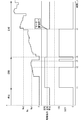
- FIG. 3 is a graph showing the transition of the rotation speed Ne of the crankshaft C during the reverse drive of the swingback control.
- the crank angle r 0
- reverse drive of the ACG starter motor 50 with a drive duty of 100% is started.
- the rotation speed Ne in the reversing direction exceeds the reversing upper limit set value Ne1 (for example, 600 rpm) as a threshold value.
- the reverse rotation upper limit setting value Ne1 is set so that the crankshaft C does not pass over the compression top dead center due to, for example, reverse rotation.
- the ECU 80 switches the drive duty from 100% to 0% when the rotation speed Ne exceeds the reverse rotation upper limit set value Ne1.
- the rotation speed Ne starts to decrease, and when the rotation speed Ne becomes the reverse rotation upper limit set value Ne1 or less, the drive duty is switched from 0% to 100%.
- the ACG starter motor 50 can continue the reverse rotation drive generally in line with the reverse rotation upper limit set value Ne1 by simple control according only to the output value of the crank angle sensor 40. Since the inertial force of the crankshaft C is large and a control delay occurs, the rotation speed Ne during the reverse rotation drive is as shown in a line graph along the reverse rotation upper limit set value Ne1.
- the graph A shown by the alternate long and short dash line shows the case where the startability is deteriorated due to the deterioration of the battery and the ACG starter motor 50
- the graph B shown by the alternate long and short dash line shows the case where the start angle of reversal is different.
- FIG. 4 is a time chart showing the flow of swingback control according to this embodiment.
- the rotation speed Ne of the crankshaft C the drive instruction of the ACG starter motor 50, and the motor duty are shown in order from the top.
- the motor duty by limiting the motor duty to two patterns of 100% or 0%, it is possible to simplify the motor control and reduce the design burden and the control burden.
- the drive instruction of the ACG starter motor 50 is "stop", the rotation speed Ne is zero, and the motor duty is also zero.
- the drive instruction is switched from “stop” to “reverse” according to the on operation of the starter switch 92, and the motor duty is switched to 100%.
- the motor duty is switched to 0% when the rotation speed Ne in the reverse direction exceeds the reverse upper limit set value Ne1.
- the motor duty is switched to 100% when the rotation speed Ne becomes equal to or less than the reverse rotation upper limit set value Ne1.
- the motor duty is switched to 100% in the forward rotation direction by switching the drive instruction from reverse rotation to forward rotation.
- the rotation speed Ne exceeds the engine start determination set value Ne3 (for example, 1000 rpm)
- the motor drive ends.
- the switching control between the motor duty 100% and 0% during the motor drive can be executed not only during the reverse rotation drive of the swingback control but also during the forward rotation drive after the reverse rotation drive.
- the ACG starter motor supports the engine until the start is completed, and the engine can be started reliably.
- FIG. 5 is a flowchart showing the procedure of engine start control according to the present embodiment.
- step S1 it is determined whether or not the starter switch 92 is turned on, and if affirmative determination is made, the process proceeds to step S2. If a negative determination is made in step S1, the determination returns to step S1.
- step S1 If affirmative judgment is made in step S1, the starter relay is turned on in step S2. In step S3, the motor duty for driving the ACG starter motor 50 in the reverse direction is set to 100%. In step S4, the motor reverse rotation drive command is output.
- step S5 it is determined whether or not the rotation speed Ne (reverse rotation Ne) exceeds the reverse rotation upper limit set value Ne1, and if an affirmative determination is made, the motor duty is switched to 0% in step S6, while a negative determination is made. , 100% motor duty is maintained in step S7.
- step S8 it is determined whether or not the compression top is detected. Specifically, it is determined at a position slightly advanced in the forward rotation direction from the compression top dead center whether or not it is within a predetermined range for terminating the reverse rotation drive.
- step S9 forward rotation drive is started with a motor duty of 100%.
- step S10 the motor forward rotation drive command is output.
- step S11 it is determined whether or not the rotation speed (normal rotation Ne) exceeds the normal rotation upper limit set value Ne2, and if an affirmative determination is made, the motor duty is switched to 0% in step S12, while a negative determination is made. Then, in step S13, the motor duty of 100% is maintained. Since it is necessary to pass the compression top dead center, the forward rotation upper limit set value Ne2 at the time of forward rotation drive can be set to a value equal to or slightly larger than the reverse rotation upper limit setting value Ne1 (for example, 600 rpm).
- step S14 it is determined whether or not the rotation speed (normal rotation Ne) exceeds the engine start determination set value Ne3 (for example, 1000 rpm), and if affirmative determination is made, the process proceeds to step S15 and the starter relay is turned off. , Ends a series of controls. On the other hand, if a negative determination is made in step S14, the determination returns to the determination in step S11.
- the rotation speed normally rotation Ne
- Ne3 for example, 1000 rpm
- the ECU 80 executes swingback control for reversely driving the crankshaft C to a predetermined range when the engine E is started, and the ECU 8 performs swingback control.
- the rotation speed Ne exceeds the threshold Ne1
- the drive of the ACG starter motor 50 is stopped (0% duty is set)
- the rotation speed Ne becomes equal to or less than the threshold Ne1 during swingback control the ACG starter motor 50 is driven. (100% duty), so it is possible to accurately stop the ACG starter motor 50 within a predetermined range by switching the drive on and off according to the rotation speed of the ACG starter motor during the reverse drive of the swingback control.
- the form of the motorcycle, the form of the ACG starter motor and the crank angle sensor, the upper limit setting value of the rotation speed, etc. are not limited to the above embodiment and can be changed in various ways.
- the engine starting device according to the present invention is not limited to a motorcycle, but can be applied to a saddle-mounted tricycle, a four-wheeled vehicle, or the like.
Landscapes
- Engineering & Computer Science (AREA)
- Chemical & Material Sciences (AREA)
- Combustion & Propulsion (AREA)
- Mechanical Engineering (AREA)
- General Engineering & Computer Science (AREA)
- Combined Controls Of Internal Combustion Engines (AREA)
- Control Of Vehicle Engines Or Engines For Specific Uses (AREA)
- Automatic Cycles, And Cycles In General (AREA)
Priority Applications (3)
| Application Number | Priority Date | Filing Date | Title |
|---|---|---|---|
| JP2022532318A JP7284351B2 (ja) | 2020-06-16 | 2021-04-01 | エンジン始動装置および鞍乗型車両 |
| BR112022020066A BR112022020066A2 (pt) | 2020-06-16 | 2021-04-01 | Dispositivo de partida do motor e veículo de conduzir montado em selim |
| CN202180041253.1A CN115715350A (zh) | 2020-06-16 | 2021-04-01 | 发动机起动装置及跨骑式车辆 |
Applications Claiming Priority (2)
| Application Number | Priority Date | Filing Date | Title |
|---|---|---|---|
| JP2020-103778 | 2020-06-16 | ||
| JP2020103778 | 2020-06-16 |
Publications (1)
| Publication Number | Publication Date |
|---|---|
| WO2021256050A1 true WO2021256050A1 (ja) | 2021-12-23 |
Family
ID=79267827
Family Applications (1)
| Application Number | Title | Priority Date | Filing Date |
|---|---|---|---|
| PCT/JP2021/014214 Ceased WO2021256050A1 (ja) | 2020-06-16 | 2021-04-01 | エンジン始動装置および鞍乗型車両 |
Country Status (5)
| Country | Link |
|---|---|
| JP (1) | JP7284351B2 (https=) |
| CN (1) | CN115715350A (https=) |
| BR (1) | BR112022020066A2 (https=) |
| TW (1) | TWI788877B (https=) |
| WO (1) | WO2021256050A1 (https=) |
Citations (3)
| Publication number | Priority date | Publication date | Assignee | Title |
|---|---|---|---|---|
| JP2000283010A (ja) * | 1999-03-30 | 2000-10-10 | Honda Motor Co Ltd | エンジン始動装置 |
| WO2002027182A1 (en) * | 2000-09-28 | 2002-04-04 | Mitsuba Corporation | Engine starter |
| JP2011021588A (ja) * | 2009-07-21 | 2011-02-03 | Honda Motor Co Ltd | エンジン始動制御装置 |
Family Cites Families (6)
| Publication number | Priority date | Publication date | Assignee | Title |
|---|---|---|---|---|
| JP4376119B2 (ja) * | 2004-04-28 | 2009-12-02 | 本田技研工業株式会社 | 内燃機関の制御装置 |
| JP4573298B2 (ja) * | 2005-03-22 | 2010-11-04 | 本田技研工業株式会社 | 内燃機関の回転変動制御装置 |
| JP5693786B2 (ja) * | 2012-04-03 | 2015-04-01 | 三菱電機株式会社 | 内燃機関の自動停止再始動装置 |
| JP6108568B1 (ja) * | 2015-09-28 | 2017-04-05 | 本田技研工業株式会社 | 鞍乗型車両のエンジン始動制御装置 |
| JP6863216B2 (ja) * | 2017-10-12 | 2021-04-21 | トヨタ自動車株式会社 | 内燃機関の制御装置 |
| JP6757371B2 (ja) * | 2018-07-27 | 2020-09-16 | 本田技研工業株式会社 | エンジン始動装置 |
-
2021
- 2021-04-01 JP JP2022532318A patent/JP7284351B2/ja active Active
- 2021-04-01 WO PCT/JP2021/014214 patent/WO2021256050A1/ja not_active Ceased
- 2021-04-01 CN CN202180041253.1A patent/CN115715350A/zh active Pending
- 2021-04-01 BR BR112022020066A patent/BR112022020066A2/pt active Search and Examination
- 2021-06-11 TW TW110121270A patent/TWI788877B/zh active
Patent Citations (3)
| Publication number | Priority date | Publication date | Assignee | Title |
|---|---|---|---|---|
| JP2000283010A (ja) * | 1999-03-30 | 2000-10-10 | Honda Motor Co Ltd | エンジン始動装置 |
| WO2002027182A1 (en) * | 2000-09-28 | 2002-04-04 | Mitsuba Corporation | Engine starter |
| JP2011021588A (ja) * | 2009-07-21 | 2011-02-03 | Honda Motor Co Ltd | エンジン始動制御装置 |
Also Published As
| Publication number | Publication date |
|---|---|
| JP7284351B2 (ja) | 2023-05-30 |
| TW202200893A (zh) | 2022-01-01 |
| TWI788877B (zh) | 2023-01-01 |
| JPWO2021256050A1 (https=) | 2021-12-23 |
| CN115715350A (zh) | 2023-02-24 |
| BR112022020066A2 (pt) | 2022-11-22 |
Similar Documents
| Publication | Publication Date | Title |
|---|---|---|
| TWI373554B (https=) | ||
| JP7812504B2 (ja) | 電気駆動可能な自転車の電気駆動モータを起動するための方法 | |
| CN103287543B (zh) | 电动辅助自行车 | |
| JP5547344B2 (ja) | エンジン制御装置 | |
| JP2016514649A (ja) | ペダル駆動式車両および該ペダル駆動式車両を動作させる方法 | |
| JP2015098227A (ja) | 電動補助車両 | |
| JP2005248921A (ja) | エンジン始動制御装置 | |
| JP6034504B2 (ja) | アイドルストップ制御装置 | |
| JP6272063B2 (ja) | 伝動システム | |
| WO2019087450A1 (ja) | 鞍乗型車両 | |
| JP6108568B1 (ja) | 鞍乗型車両のエンジン始動制御装置 | |
| JP7284351B2 (ja) | エンジン始動装置および鞍乗型車両 | |
| JP6823159B2 (ja) | 車両のエンジン制御装置 | |
| JP5703077B2 (ja) | ハイブリッド車両における回生システム | |
| JP5794047B2 (ja) | 自動二輪車の制御装置 | |
| JP5373449B2 (ja) | 三相モータ制御装置 | |
| JP5805614B2 (ja) | エンジン始動制御装置 | |
| JP4738066B2 (ja) | 電動自転車 | |
| JP7490482B2 (ja) | 燃料噴射方法および燃料噴射装置 | |
| JP5838877B2 (ja) | エンジンの停止制御装置 | |
| JP7255017B2 (ja) | エンジン制御装置の制御方法および鞍乗型車両 | |
| CN112814791B (zh) | 车辆的启动系统 | |
| JP2016128310A (ja) | 電動パワーステアリング装置 | |
| JP2022020418A (ja) | エンジン点火方法およびエンジン点火装置 | |
| JP4527736B2 (ja) | 車両およびその制御方法並びに駆動装置 |
Legal Events
| Date | Code | Title | Description |
|---|---|---|---|
| 121 | Ep: the epo has been informed by wipo that ep was designated in this application |
Ref document number: 21826567 Country of ref document: EP Kind code of ref document: A1 |
|
| ENP | Entry into the national phase |
Ref document number: 2022532318 Country of ref document: JP Kind code of ref document: A |
|
| REG | Reference to national code |
Ref country code: BR Ref legal event code: B01A Ref document number: 112022020066 Country of ref document: BR |
|
| ENP | Entry into the national phase |
Ref document number: 112022020066 Country of ref document: BR Kind code of ref document: A2 Effective date: 20221004 |
|
| NENP | Non-entry into the national phase |
Ref country code: DE |
|
| 122 | Ep: pct application non-entry in european phase |
Ref document number: 21826567 Country of ref document: EP Kind code of ref document: A1 |