WO2021255854A1 - 印刷装置及び印刷方法 - Google Patents
印刷装置及び印刷方法 Download PDFInfo
- Publication number
- WO2021255854A1 WO2021255854A1 PCT/JP2020/023745 JP2020023745W WO2021255854A1 WO 2021255854 A1 WO2021255854 A1 WO 2021255854A1 JP 2020023745 W JP2020023745 W JP 2020023745W WO 2021255854 A1 WO2021255854 A1 WO 2021255854A1
- Authority
- WO
- WIPO (PCT)
- Prior art keywords
- printing
- bent portion
- work
- flat portion
- center line
- Prior art date
- Legal status (The legal status is an assumption and is not a legal conclusion. Google has not performed a legal analysis and makes no representation as to the accuracy of the status listed.)
- Ceased
Links
Images


Classifications
-
- B—PERFORMING OPERATIONS; TRANSPORTING
- B41—PRINTING; LINING MACHINES; TYPEWRITERS; STAMPS
- B41F—PRINTING MACHINES OR PRESSES
- B41F15/00—Screen printers
- B41F15/08—Machines
-
- B—PERFORMING OPERATIONS; TRANSPORTING
- B41—PRINTING; LINING MACHINES; TYPEWRITERS; STAMPS
- B41F—PRINTING MACHINES OR PRESSES
- B41F15/00—Screen printers
- B41F15/14—Details
- B41F15/16—Printing tables
- B41F15/18—Supports for workpieces
- B41F15/30—Supports for workpieces for articles with curved surfaces
-
- B—PERFORMING OPERATIONS; TRANSPORTING
- B41—PRINTING; LINING MACHINES; TYPEWRITERS; STAMPS
- B41M—PRINTING, DUPLICATING, MARKING, OR COPYING PROCESSES; COLOUR PRINTING
- B41M1/00—Inking and printing with a printer's forme
- B41M1/12—Stencil printing; Silk-screen printing
Definitions
- the present invention relates to a printing apparatus and a printing method. It is particularly related to screen printing equipment.
- the present invention provides a printing device for a workpiece having a bent surface.
- the printing apparatus of the present invention is A printing table on which a workpiece having a bent portion whose cross section is an arc on a vertical plane parallel to the printing direction is placed, A strut to which the rotation axis of the printing table is rotatably attached around the center line of the bent portion, and A drive unit that rotates the printing table around the center line, A moving table on which the support column and the drive unit are fixed, It was provided with a housing to which the moving table was movably attached.
- printing can be performed on a work having a bent surface.
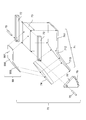
- FIG. 1 The front view of the printing apparatus 100 in Embodiment 1.
- FIG. 1 The right side view of the printing apparatus 100 in Embodiment 1.
- FIG. 1 The plan view of the printing apparatus 100 in Embodiment 1.
- FIG. The operation explanatory drawing of the first half printing of the printing apparatus 100 in Embodiment 1.
- FIG. The explanatory view of the modification of the print table 70 in Embodiment 1.
- FIG. The explanatory view of the modification of the print table 70 and the work 99 in Embodiment 1.
- FIG. (A) and (b) are diagrams in which the bending angle is 90 degrees
- (c) is a diagram in which the work 99 is only the bent portion 992
- (d) is a diagram in which the bending angle is 180 degrees.
- FIG. The operation explanatory view of the bending printing of the printing apparatus 100 in Embodiment 2.
- Embodiment 1 *** Explanation of work 99 *** ⁇ Work 99 (Figs. 4 and 5)
- the work 99 has a bent portion 992 whose cross section is an arc on a vertical plane parallel to the printing direction. As shown in FIG. 4, the work 99 has the following. ⁇ Front flat part 991 ⁇ Bent part 992 ⁇ Rear flat part 993
- the front flat portion 991 is a first half portion of printing and is a portion exhibiting a flat surface.
- the bent portion 992 is a central portion of printing and is a bent portion.
- the rear flat portion 993 is a latter half portion of printing and is a portion exhibiting a flat surface.
- the radius of the arc of the bent portion 992 is R.
- the line passing through the center of the arc of the bent portion 992 is defined as the center line C of the bent portion 992.
- the bending angle of the work 99 is K degrees. That is, when the front flat portion 991 is installed horizontally, the rear flat portion 993 is tilted downward by K degrees from the horizontal.
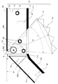
- FIG. 1, FIG. 2, FIG. 3 The configuration of the printing apparatus 100 will be described with reference to FIGS. 1, 2, and 3.
- a specific example of the printing device 100 is a screen printing device.
- the left-right direction toward the paper surface is also referred to as a lateral direction.
- the vertical direction toward the paper surface is also referred to as a vertical direction.
- the depth direction toward the paper surface is also referred to as the width direction.
- the printing direction of the printing apparatus 100 is the left direction.
- the printing apparatus 100 screen-prints the work 99 placed on the printing table 70.
- the printing apparatus 100 uses the screen 91 to perform screen printing using the squeegee 92.
- the printing apparatus 100 has the following. ⁇ Housing 51 ⁇ Mobile table 52 ⁇ Prop 53 ⁇ Cylinder 54 ⁇ Stopper 55 ⁇ Drive unit 56 ⁇ Control unit 60 ⁇ Printing table 70
- the housing 51 is the base of the printing apparatus 100.
- the housing 51 is a rectangular metal plate that is long in the left-right direction.
- the housing 51 is arranged horizontally.
- the moving table 52 is attached so as to be movable in the left-right direction with respect to the housing 51.
- the moving table 52 is a rectangular metal plate that is long in the left-right direction.
- the mobile table 52 fixes the following. (1) Support 53 (2) Cylinder 54 (3) Stopper 55 (4) Drive unit 56 (5) Control unit 60
- a pair of columns 53 are provided in the width direction of the moving table 52.
- the pillar 53 is a pillar fixed to the moving table 52.
- the support column 53 is made of bakelite or metal.
- a printing table 70 is rotatably attached to the upper portion of the support column 53.
- the support column 53 rotatably attaches the printing table 70 around the center line C of the bent portion 992 of the work 99.
- Cylinder 54 A pair of cylinders 54 are provided in the left-right direction and are fixed to the moving table 52.
- the cylinder 54 can move the rod up and down.
- the tip of the rod is hemispherical.
- the cylinder 54 supports the lower surface of the printing table 70 at the time of printing.
- the left cylinder 54 corresponds to the lower left surface of the printing table 70, and supports the lower left surface of the printing table 70 so that the left side of the printing table 70 is horizontal.
- the right cylinder 54 corresponds to the lower right side of the printing table 70, and supports the lower right side of the printing table 70 so that the right side of the printing table 70 is horizontal.
- Stopper 55 A pair of stoppers 55 are provided in the left-right direction and are fixed to the moving table 52.
- the stopper 55 can adjust the vertical position of the rod.
- the tip of the rod is hemispherical.
- the stopper 55 supports the lower surface of the printing table 70 during non-printing.
- the left stopper 55 corresponds to the lower left surface of the printing table 70, and prohibits the left side of the printing table 70 from rotating above the horizontal plane.
- the right stopper 55 corresponds to the lower surface on the right side of the printing table 70, and prohibits the right side of the printing table 70 from rotating above the horizontal plane.
- the drive unit 56 rotates the gear 77 to rotate the printing table.
- the drive unit 56 has a link mechanism 30 that converts linear motion into rotary motion.
- the link mechanism 30 of the drive unit 56 has a slide table 561 and a rack 562.
- the slide table 561 has a rack 562 attached so as to be slidable in the left-right direction.
- the teeth 58 of the rack 562 mesh with the teeth 78 of the gear 77 to rotate the gear 77.
- the slide table 561 rotates the printing table 70 around the center line C of the bent portion 992 by moving the rack 562 left and right.
- the link mechanism 30 converts the linear motion of the rack 562 into the rotational motion of the printing table 70 about the center line C of the bent portion 992.
- Control unit 60 controls the printing device 100 and controls the screen printing operation.
- the control unit 60 can be realized by a central processing unit, a program, a memory, and a storage device.
- the control signal from the control unit 60 is transmitted to each unit as an electric signal by the signal line 61.
- the screen printing operation described below can be realized by the control unit 60 transmitting and receiving commands and signals by the signal line 61.
- Printing table 70 (Figs. 4 and 5) The print table 70 will be described with reference to FIGS. 4 and 5. The work 99 is placed on the print table 70. The print table 70 swings around the rotation axis 75.
- the print table 70 has the following: (1) Bottom plate 71 (2) Bracket 72 (3) Front receiving plate 73 (4) Rear receiving plate 74 (5) Gap 76 (6) Gear 77 (7) Rotating shaft 75
- the bottom plate 71 is a base material that determines the shape of the printing table 70.
- the bottom plate 71 is made of stainless steel or other metal.
- the bottom plate 71 can be manufactured by bending one rectangular metal plate.
- the bending angle (K degree) of the bottom plate 71 is the same as the bending angle (K degree) of the work 99.
- the bottom plate 71 has the following.
- ⁇ Front flat part 711 The front flat portion 711 is a front half portion of the bottom plate 71, and is a portion exhibiting a flat surface.
- the front flat portion 711 has a length halfway through the bent portion 712.
- the left end of the front flat portion 711 extends below the center line C of the bent portion 992 of the work 99.
- ⁇ Bending part 712 The bent portion 712 is a portion slightly to the left of the central portion of the bottom plate 71, and is a bent portion.
- the bent portion 712 is bent at a radius different from that of the bent portion 992 of the work 99.
- the bent portion 712 may be bent with the same radius R as the bent portion 992 of the work 99.
- ⁇ Rear flat part 993 The rear flat portion 713 is the latter half portion of the bottom plate 71, and is a portion exhibiting a flat surface.
- Bracket 72 (Fig. 4) A pair of brackets 72 are provided in the width direction of the printing table 70.
- the bracket 72 is a columnar hexahedral rod.
- the bracket 72 is made of aluminum or other metal.
- the bracket 72 is fixed to both sides of the printing table 70 (front receiving plate 73) with screws 81 (FIG. 5).
- the bracket 72 has a length from the right end of the front flat portion 711 to the middle of the bent portion 712.
- the bracket 72 has the same length as the front flat portion 711.
- the left end of the bracket 72 covers the center line C of the bent portion 992 of the work 99.
- the bracket 72 has a rotating shaft 75 attached to the upper part of the left end.
- the bracket 72 has a rotating shaft 75 attached at a position that becomes the center line C of the bent portion 992.
- the front receiving plate 73 is a hexahedron plate.
- the front backing plate 73 is made of bakelite, plastic, other resin, or metal.
- the front receiving plate 73 is fixed to the upper surface of the front flat portion 711 with screws 83 (FIG. 5).
- the front receiving plate 73 has a length equal to or less than the length of the front flat portion 711.
- the front flat portion 991 of the work 99 is placed on the upper surface of the front receiving plate 73.
- the front receiving plate 73 is a connecting plate that connects a pair of brackets 72 in the width direction.
- the backing plate 74 is a hexahedron plate.
- the backing plate 74 is made of bakelite, plastic, other resin, or metal.
- the back receiving plate 74 is fixed to the upper surface of the rear flat portion 713 with screws 83 (FIG. 5).
- the back receiving plate 74 has a length equal to or less than the length of the rear flat portion 713.
- the rear flat portion 993 of the work 99 is placed on the upper surface of the rear support plate 74. Since the front flat portion 711 has a length up to the middle of the bent portion 712, the rear receiving plate 74 is thinner than the front receiving plate 73.
- Gap 76 (Fig. 5)
- the gap portion 76 is a space between the left end surface of the front receiving plate 73 and the right end surface of the rear receiving plate 74.
- a bent portion 992 of the work 99 is arranged on the gap portion 76.
- Gear 77 (Fig. 5)
- One gear 77 is provided on one side of the printing table 70.
- the gear 77 rotates the rotating shaft 75 of the printing table 70.
- the gear 77 is fixed to the bracket 72 of the printing table 70 with screws 82.
- the gear 77 has a fan shape.
- the gear 77 rotates about the rotation shaft 75. If the gear 77 rotates, the print table 70 also rotates.
- the internal angle of the gear 77 is L degree, and the L degree may be a bending angle of K degree or more.
- the radius M of the gear 77 is centered on the center line C (FIG. 5) of the bent portion 992 of the work 99.
- the radius M of the gear 77 is larger than the radius R of the bent portion 992 of the work 99.
- the teeth 78 of the gear 77 are arranged along an arc having a radius M.
- Rotating shaft 75 (Fig. 4) A pair of rotating shafts 75 are provided in the width direction of the printing table 70.
- the rotation shaft 75 exists in a straight line.
- the rotating shaft 75 may be a single shaft penetrating the printing table 70 in the width direction.
- the rotation axis 75 is arranged orthogonal to the printing direction and is arranged horizontally.
- the rotating shaft 75 is a shaft fixed to the support column 533.
- the rotating shaft 75 penetrates the gear 77 and the bracket 72.
- the rotary shaft 75 rotatably attaches the gear 77 and the bracket 72.
- the center line of the rotating shaft 75 coincides with the center line C of the bent portion 992.
- the control unit 60 starts the following initial operations.
- the control unit 60 moves the rack 562 of the slide table 561 to the initial position on the right side, and rotates the print table 70 so that the front half portion is horizontal as shown in FIG. 7.
- the left stopper 55 prohibits the printing table 70 from rotating significantly to the left.
- the control unit 60 places the work 99 on the printing table 70 by a loading / unloading device (not shown), and arranges the work 99 under the screen 91.
- the control unit 60 sucks the work 99 onto the printing table 70 by a suction mechanism (not shown) and fixes the work 99 to the printing table 70.
- the control unit 60 raises the rod of the right cylinder 54.
- the right cylinder 54 supports the lower surface of the front flat portion 711 in a state where the front flat portion 991 of the work 99 is parallel to the screen 91.
- the control unit 60 moves the squeegee 92 to the print start position on the right side.
- FIG. 7 is a diagram showing the first half printing.
- the first half printing step S20 is a step of fixing the front half portion of the printing table 70 on which the front flat portion 991 of the work 99 is placed in parallel with the printing direction and printing the front flat portion 991.
- the control unit 60 starts moving the squeegee 92 to the left and starts printing.
- the control unit 60 locks the slide table 561 and prohibits the rotation of the print table 70.
- the control unit 60 stops the movement of the moving table 52.
- the right cylinder 54 supports the lower surface of the front flat portion 711, so that the printing table 70 rotates clockwise or the printing table 70 is deformed even if printing pressure is applied to the front flat portion 991. There is no.
- the first half printing step S20 ends when the front flat portion 991 of the work 99 is printed.
- FIG. 8 is a diagram showing bending printing after the first half printing.
- the bending printing step S30 is a step of printing the bending portion 992 while rotating the printing table 70 around the center line C of the bending portion 992 of the work 99 and moving the printing table 70 in the printing direction. ..
- the control unit 60 simultaneously controls the following. (1) Slide the rack 562 of the slide table 561 to the left. By moving the rack 562, the gear 77 is rotated, and the printing table 70 is rotated around the rotation axis 75 (center line C). (2) The moving table 52 is moved to the left (printing direction) with respect to the housing 51.
- the printing table 70 is rotated by rotating the gear 77 having a radius L larger than the radius R of the bending portion 992.
- the lower surface of the bent portion 992 is a gap portion 76, but even if printing pressure is applied to the bent portion 992, the bent portion 992 exhibits a convex curved surface, so that the bent portion 992 is not deformed.
- the bending printing step S30 ends when the bending portion 992 of the work 99 is printed.
- FIG. 9 is a diagram showing a latter half printing process after bending printing.
- the latter half printing step S40 is a step of fixing the latter half of the printing table 70 on which the rear flat portion 993 of the work 99 is placed in parallel with the printing direction and printing the rear flat portion 993.
- the control unit 60 continues to move the squeegee 92 to the left.
- the control unit 60 locks the slide table 561 and prohibits the rotation of the print table 70.
- the control unit 60 stops the movement of the moving table 52.
- the second half printing step S40 ends when the rear flat portion 993 of the work 99 is printed.
- control unit 60 When printing is completed, the control unit 60 carries out the work 99 for which printing has been completed by an loading / unloading device (not shown). After carrying out the work 99, the control unit 60 determines whether or not there is a next print, and if there is a next print, returns to the preparation step S10. The control unit 60 ends printing if there is no next print.
- the arc length E of the bent portion 992 is as follows.
- the arc length E of the bent portion 992 is as follows.
- the control unit 60 performs the following control. (1) Slide the rack 562 of the slide table 561 to the left so that the gear 77 is rotated clockwise by 35 degrees. By rotating the gear 77 clockwise by 35 degrees, the print table 70 is rotated clockwise by 35 degrees around the rotation axis 75. (2) The moving table 52 is moved to the left (printing direction) by 3.05 mm with respect to the housing 51. (3) The squeegee 92 is moved to the left (printing direction) by 3.05 mm.
- the conventional curved surface printing mechanism is for a gentle curved surface, and may not be suitable for printing a curved surface having a small radius.
- printing can be performed on a bent portion having an arc having a small radius.
- the radius M of the gear 77 is larger than the radius R of the bent portion 992 of the work 99, it is possible to rotate with high accuracy.
- by producing only the bottom plate 71 whose bending angle is the same as the bending angle of the work 99 it can be shared with other parts of the printing table 70.
- the drive unit 56 shown in FIG. 10 has a motor 563 and a gear 564.
- the control unit 60 can rotate the gear 564 by the motor 563 to rotate the printing table 70.
- the gear 564 does not have to be fan-shaped and may be circular or semi-circular.
- the cylinder 54 and the stopper 55 shown in FIG. 10 are arranged sideways. By arranging the cylinder 54 and the stopper 55 sideways, the sky above the moving table 52 is vacant, and the rotation angle of the printing table 70 can be expanded.
- the cylinder 54 and the stopper 55 may be used in combination with one cylinder. Further, if the fixing of the printing table 70 by the gear 77 and the driving unit 56 is strong enough to withstand the printing pressure, the cylinder 54 is unnecessary.
- the printing table 70 shown in FIG. 11 has no front receiving plate 73 and no rear receiving plate 74, and has a bottom plate 71 and a bracket 72.
- the bracket 72 has a cubic shape and has a through hole in the center through which the rotation shaft 75 penetrates.
- the bracket 72 is fixed to both sides of the bent portion 712 of the bottom plate 71 by screws (not shown).
- the front flat portion 711 of the bottom plate 71 supports the front flat portion 991 of the work 99 from below.
- the bent portion 712 of the bottom plate 71 has the same arc as the bent portion 992 of the work 99.
- the bent portion 712 of the bottom plate 71 supports the bent portion 992 of the work 99 from below.
- the rear flat portion 713 of the bottom plate 71 supports the rear flat portion 993 of the work 99 from below.
- the gear 77 does not have to be fan-shaped, and may be circular or semi-circular. 12 (a) and 12 (b) are views in which the bending angle is 90 degrees. The internal angle of the gear 77 needs to be 90 degrees or more.
- the work 99 may have only the front flat portion 991 and the bent portion 992, and may not have the rear flat portion 993.
- the work 99 may not have the front flat portion 991 but may have only the bent portion 992 and the rear flat portion 993.
- FIG. 12 (c) is a diagram in which the work 99 has only the bent portion 992.
- the bent portion 992 of the work 99 is sucked by the printing table 70 and fixed to the printing table 70.
- FIG. 12D is a diagram in which the internal angle and the bending angle of the bent portion 992 are 180 degrees.
- the work 99 and the printing table 70 are bent in a U shape.
- the internal angle of the gear 77 needs to be 180 degrees or more.
- Embodiment 2 In the second embodiment, the differences from the first embodiment will be described.
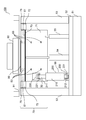
- Printing device 100 (FIG. 13, FIG. 14, FIG. 15)
- the configuration of the printing apparatus 100 will be described with reference to FIGS. 13, 14, and 15.
- a specific example of the printing device 100 is a screen printing device.
- the printing device 100 of the second embodiment does not have the gear 77, and the configuration of the drive unit 56 is different.
- the drive unit 56 has a link mechanism 30 that converts linear motion into rotary motion.
- the link mechanism 30 of the drive unit 56 has a crank mechanism 200.
- the drive unit 56 is arranged on the left side of the lower surface of the print table 70.
- the print table 70 has a receiving portion 220 fixed to the back surface of the rear flat portion 713.
- the receiving portion 220 has a bifurcated shape.
- the mobile table 52 has a clevis 230 fixed to the mobile table 52.
- the clevis 230 is located below the front flat portion 711.
- the clevis 230 has a bifurcated shape.
- the crank mechanism 200 has a receiving portion 220, a crank cylinder 210, a crankshaft 211, and a clevis 230.
- the crankshaft 211 is linearly moved on the central axis of the crank cylinder 210 by a linear servomotor.
- the upper end of the crankshaft 211 is rotatably attached to the receiving portion 220 by a pin 221.
- the pins 221 are orthogonal to the printing direction and are arranged horizontally.
- a cylinder joint 212 is fixed to the lower end of the crank cylinder 210.
- the cylinder joint 212 is rotatably attached to the clevis 230 by a pin 231.
- the pins 231 are orthogonal to the printing direction and are arranged horizontally.
- the upper end and the lower end of the crank mechanism 200 are rotatable, and the angle of intersection with the upper surface of the moving table 52 can be passively changed by the telescopic slide of the crankshaft 211.
- the crankshaft 211 rotates the printing table 70 around the center line C of the bent portion 992.
- the link mechanism 30 converts the linear motion of the crankshaft 211 into the rotational motion of the printing table 70 about the center line C of the bent portion 992.
- FIG. 16 is a diagram showing bending printing after the first half printing.
- the control unit 60 slides the crankshaft 211 to the upper left when printing the bent portion 992 of the work 99.
- the control unit 60 pushes up the receiving unit 220 upward by moving the crankshaft 211 forward to the upper left.
- the receiving portion 220 rotates clockwise around the rotation axis 75 (center line C), and rotates the printing table 70 clockwise around the rotation axis 75 (center line C).
- the cylinder joint 212 is rotatably attached to the moving table 52 by the clevis 230, when the receiving portion 220 is pushed upward, the tilt angle of the crank cylinder 210 with respect to the horizontal direction becomes large.
- the crankshaft 211 is rotatably attached to the printing table 70 by the receiving portion 220, when the receiving portion 220 is pushed upward, the tilt angle of the crankshaft 211 with respect to the horizontal direction becomes large.
- the printing table 70 is rotated by pushing up the printing table 70 with the crank mechanism 200.
- the arc length P to which the pin 221 moves is as follows.
- the control unit 60 moves the crankshaft 211 forward so that the pin 221 moves at a constant speed when the pin 221 moves along the arc length P.
- the pin 221 moves the arc length P, so that the bent portion 992 of the arc length E is printed. Will be done.
- the drive unit 56 is arranged so as to intersect the bent portion 992, but may be arranged only on the left side of the bent portion 992 or only on the right side of the bent portion 992.
- the drive unit 56 may be arranged in the center of the lower surface of the printing table 70 instead of the left side of the lower surface.
- Link mechanism 30 is not limited to the crank mechanism 200, and may be any mechanism that converts linear motion into rotational motion of the printing table centered on the center line C of the bent portion 992.
Landscapes
- Engineering & Computer Science (AREA)
- Mechanical Engineering (AREA)
- Screen Printers (AREA)
- Printing Methods (AREA)
- Dot-Matrix Printers And Others (AREA)
- Printers Characterized By Their Purpose (AREA)
Priority Applications (4)
| Application Number | Priority Date | Filing Date | Title |
|---|---|---|---|
| CN202080101568.6A CN115666950A (zh) | 2020-06-17 | 2020-06-17 | 印刷装置及印刷方法 |
| JP2022531166A JP7273448B2 (ja) | 2020-06-17 | 2020-06-17 | 印刷装置及び印刷方法 |
| PCT/JP2020/023745 WO2021255854A1 (ja) | 2020-06-17 | 2020-06-17 | 印刷装置及び印刷方法 |
| TW109129682A TWI792050B (zh) | 2020-06-17 | 2020-08-31 | 印刷裝置及印刷方法 |
Applications Claiming Priority (1)
| Application Number | Priority Date | Filing Date | Title |
|---|---|---|---|
| PCT/JP2020/023745 WO2021255854A1 (ja) | 2020-06-17 | 2020-06-17 | 印刷装置及び印刷方法 |
Publications (1)
| Publication Number | Publication Date |
|---|---|
| WO2021255854A1 true WO2021255854A1 (ja) | 2021-12-23 |
Family
ID=79268713
Family Applications (1)
| Application Number | Title | Priority Date | Filing Date |
|---|---|---|---|
| PCT/JP2020/023745 Ceased WO2021255854A1 (ja) | 2020-06-17 | 2020-06-17 | 印刷装置及び印刷方法 |
Country Status (4)
| Country | Link |
|---|---|
| JP (1) | JP7273448B2 (https=) |
| CN (1) | CN115666950A (https=) |
| TW (1) | TWI792050B (https=) |
| WO (1) | WO2021255854A1 (https=) |
Cited By (1)
| Publication number | Priority date | Publication date | Assignee | Title |
|---|---|---|---|---|
| JP2024137641A (ja) * | 2023-03-24 | 2024-10-07 | ビルト-イン プレシジョン マシン カンパニー リミテッド | スクリーン印刷機及びスクリーン印刷方法 |
Citations (8)
| Publication number | Priority date | Publication date | Assignee | Title |
|---|---|---|---|---|
| JPH01178499A (ja) * | 1988-01-11 | 1989-07-14 | Koito Mfg Co Ltd | 曲面印刷方法及び曲面印刷装置 |
| JPH0395236U (https=) * | 1990-01-18 | 1991-09-27 | ||
| JPH05254087A (ja) * | 1992-03-14 | 1993-10-05 | Taiyo Yuden Co Ltd | グリーンシートのパターン印刷方法及び装置 |
| KR100826216B1 (ko) * | 2006-12-26 | 2008-04-30 | 장도영 | 원추형 인쇄물 스크린 인쇄장치 |
| WO2017086137A1 (ja) * | 2015-11-18 | 2017-05-26 | 旭硝子株式会社 | 印刷版、印刷装置、基材及び基材の製造方法 |
| WO2017086197A1 (ja) * | 2015-11-18 | 2017-05-26 | 旭硝子株式会社 | 曲面スクリーン印刷装置、曲面スクリーン印刷方法、及び印刷層を有する基材の製造方法 |
| JP2017094718A (ja) * | 2015-11-18 | 2017-06-01 | 旭硝子株式会社 | スクリーン印刷方法及びスクリーン印刷装置、並びに印刷層付き基材の製造方法及び基材 |
| JP2017209982A (ja) * | 2016-04-04 | 2017-11-30 | マイクロ・テック株式会社 | ワーク操作装置、ワーク操作方法、曲面治具、曲面治具の製造方法及びスクリーン印刷装置 |
Family Cites Families (4)
| Publication number | Priority date | Publication date | Assignee | Title |
|---|---|---|---|---|
| CN101098784B (zh) * | 2005-01-17 | 2010-12-01 | 株式会社村田制作所 | 丝网印刷装置和丝网印刷方法 |
| JP6767181B2 (ja) * | 2016-06-30 | 2020-10-14 | 株式会社セリアエンジニアリング | スクリーン印刷機 |
| JP7054131B2 (ja) * | 2017-08-10 | 2022-04-13 | マイクロ・テック株式会社 | スクリーン印刷装置及びスクリーン印刷方法 |
| CN210126344U (zh) * | 2019-02-15 | 2020-03-06 | 佛山市力美照明科技股份有限公司 | 一种用于灯泡的丝印机 |
-
2020
- 2020-06-17 WO PCT/JP2020/023745 patent/WO2021255854A1/ja not_active Ceased
- 2020-06-17 CN CN202080101568.6A patent/CN115666950A/zh active Pending
- 2020-06-17 JP JP2022531166A patent/JP7273448B2/ja active Active
- 2020-08-31 TW TW109129682A patent/TWI792050B/zh not_active IP Right Cessation
Patent Citations (8)
| Publication number | Priority date | Publication date | Assignee | Title |
|---|---|---|---|---|
| JPH01178499A (ja) * | 1988-01-11 | 1989-07-14 | Koito Mfg Co Ltd | 曲面印刷方法及び曲面印刷装置 |
| JPH0395236U (https=) * | 1990-01-18 | 1991-09-27 | ||
| JPH05254087A (ja) * | 1992-03-14 | 1993-10-05 | Taiyo Yuden Co Ltd | グリーンシートのパターン印刷方法及び装置 |
| KR100826216B1 (ko) * | 2006-12-26 | 2008-04-30 | 장도영 | 원추형 인쇄물 스크린 인쇄장치 |
| WO2017086137A1 (ja) * | 2015-11-18 | 2017-05-26 | 旭硝子株式会社 | 印刷版、印刷装置、基材及び基材の製造方法 |
| WO2017086197A1 (ja) * | 2015-11-18 | 2017-05-26 | 旭硝子株式会社 | 曲面スクリーン印刷装置、曲面スクリーン印刷方法、及び印刷層を有する基材の製造方法 |
| JP2017094718A (ja) * | 2015-11-18 | 2017-06-01 | 旭硝子株式会社 | スクリーン印刷方法及びスクリーン印刷装置、並びに印刷層付き基材の製造方法及び基材 |
| JP2017209982A (ja) * | 2016-04-04 | 2017-11-30 | マイクロ・テック株式会社 | ワーク操作装置、ワーク操作方法、曲面治具、曲面治具の製造方法及びスクリーン印刷装置 |
Cited By (1)
| Publication number | Priority date | Publication date | Assignee | Title |
|---|---|---|---|---|
| JP2024137641A (ja) * | 2023-03-24 | 2024-10-07 | ビルト-イン プレシジョン マシン カンパニー リミテッド | スクリーン印刷機及びスクリーン印刷方法 |
Also Published As
| Publication number | Publication date |
|---|---|
| CN115666950A (zh) | 2023-01-31 |
| JP7273448B2 (ja) | 2023-05-15 |
| JPWO2021255854A1 (https=) | 2021-12-23 |
| TW202200400A (zh) | 2022-01-01 |
| TWI792050B (zh) | 2023-02-11 |
Similar Documents
| Publication | Publication Date | Title |
|---|---|---|
| KR101993113B1 (ko) | 용접용 틸팅테이블 | |
| TWI633943B (zh) | 零件分選機構及分選方法、零件供應系統 | |
| CN114590046B (zh) | 一种异形锥体工件丝网印刷方法及其印刷设备 | |
| WO2021255854A1 (ja) | 印刷装置及び印刷方法 | |
| JP2010253673A (ja) | 作業台 | |
| JPH0839767A (ja) | スクリーン印刷装置 | |
| CN114340900B (zh) | 摇摆工作台、工作台摇摆方法、以及网版印刷装置 | |
| JP6892560B2 (ja) | クランプレールユニット | |
| JP7068724B2 (ja) | 印刷製版、印刷機、印刷製版の製造方法、及び、印刷方法 | |
| CN101472394A (zh) | 对位装置 | |
| JP2007015072A (ja) | 自動回転ステージ | |
| CN207449362U (zh) | 一种自动定位印刷平台机构 | |
| CN215478019U (zh) | 一种镜头翻转结构 | |
| KR102466628B1 (ko) | 폴더블 디스플레이 유니버셜 폴딩 테스트 장치 | |
| JP5610937B2 (ja) | 傾斜回転鍛造装置 | |
| JPH056124Y2 (https=) | ||
| JP2003181686A (ja) | ワーク位置決め装置 | |
| JP2023018391A (ja) | スクリーン印刷装置及びスクリーン印刷方法 | |
| CN221976026U (zh) | 一种定向三维扫描标定板 | |
| KR101547068B1 (ko) | 스크린 프린터 | |
| CN119822053A (zh) | 一种手机屏幕夹取单元及手机屏幕夹取定位装置 | |
| JPH0641696Y2 (ja) | 板材加工機におけるクランプ装置 | |
| JP2005040848A (ja) | 回転割出しテーブル装置および同装置を用いた板材折曲げ加工装置 | |
| WO2022013999A1 (ja) | スクリーン印刷装置及びスクリーン印刷方法 | |
| JP2537832Y2 (ja) | 鉄骨仕口材溶接装置 |
Legal Events
| Date | Code | Title | Description |
|---|---|---|---|
| 121 | Ep: the epo has been informed by wipo that ep was designated in this application |
Ref document number: 20941395 Country of ref document: EP Kind code of ref document: A1 |
|
| ENP | Entry into the national phase |
Ref document number: 2022531166 Country of ref document: JP Kind code of ref document: A |
|
| NENP | Non-entry into the national phase |
Ref country code: DE |
|
| 122 | Ep: pct application non-entry in european phase |
Ref document number: 20941395 Country of ref document: EP Kind code of ref document: A1 |