WO2021255854A1 - 印刷装置及び印刷方法 - Google Patents
印刷装置及び印刷方法 Download PDFInfo
- Publication number
- WO2021255854A1 WO2021255854A1 PCT/JP2020/023745 JP2020023745W WO2021255854A1 WO 2021255854 A1 WO2021255854 A1 WO 2021255854A1 JP 2020023745 W JP2020023745 W JP 2020023745W WO 2021255854 A1 WO2021255854 A1 WO 2021255854A1
- Authority
- WO
- WIPO (PCT)
- Prior art keywords
- printing
- bent portion
- work
- flat portion
- center line
- Prior art date
Links
Images


Classifications
-
- B—PERFORMING OPERATIONS; TRANSPORTING
- B41—PRINTING; LINING MACHINES; TYPEWRITERS; STAMPS
- B41F—PRINTING MACHINES OR PRESSES
- B41F15/00—Screen printers
- B41F15/08—Machines
-
- B—PERFORMING OPERATIONS; TRANSPORTING
- B41—PRINTING; LINING MACHINES; TYPEWRITERS; STAMPS
- B41F—PRINTING MACHINES OR PRESSES
- B41F15/00—Screen printers
- B41F15/14—Details
- B41F15/16—Printing tables
- B41F15/18—Supports for workpieces
- B41F15/30—Supports for workpieces for articles with curved surfaces
-
- B—PERFORMING OPERATIONS; TRANSPORTING
- B41—PRINTING; LINING MACHINES; TYPEWRITERS; STAMPS
- B41M—PRINTING, DUPLICATING, MARKING, OR COPYING PROCESSES; COLOUR PRINTING
- B41M1/00—Inking and printing with a printer's forme
- B41M1/12—Stencil printing; Silk-screen printing
Definitions
- the present invention relates to a printing apparatus and a printing method. It is particularly related to screen printing equipment.
- the present invention provides a printing device for a workpiece having a bent surface.
- the printing apparatus of the present invention is A printing table on which a workpiece having a bent portion whose cross section is an arc on a vertical plane parallel to the printing direction is placed, A strut to which the rotation axis of the printing table is rotatably attached around the center line of the bent portion, and A drive unit that rotates the printing table around the center line, A moving table on which the support column and the drive unit are fixed, It was provided with a housing to which the moving table was movably attached.
- printing can be performed on a work having a bent surface.
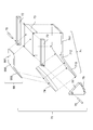
- FIG. 1 The front view of the printing apparatus 100 in Embodiment 1.
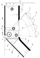
- FIG. 1 The right side view of the printing apparatus 100 in Embodiment 1.
- FIG. 1 The plan view of the printing apparatus 100 in Embodiment 1.
- FIG. The operation explanatory drawing of the first half printing of the printing apparatus 100 in Embodiment 1.
- FIG. The explanatory view of the modification of the print table 70 in Embodiment 1.
- FIG. The explanatory view of the modification of the print table 70 and the work 99 in Embodiment 1.
- FIG. (A) and (b) are diagrams in which the bending angle is 90 degrees
- (c) is a diagram in which the work 99 is only the bent portion 992
- (d) is a diagram in which the bending angle is 180 degrees.
- FIG. The operation explanatory view of the bending printing of the printing apparatus 100 in Embodiment 2.
- Embodiment 1 *** Explanation of work 99 *** ⁇ Work 99 (Figs. 4 and 5)
- the work 99 has a bent portion 992 whose cross section is an arc on a vertical plane parallel to the printing direction. As shown in FIG. 4, the work 99 has the following. ⁇ Front flat part 991 ⁇ Bent part 992 ⁇ Rear flat part 993
- the front flat portion 991 is a first half portion of printing and is a portion exhibiting a flat surface.
- the bent portion 992 is a central portion of printing and is a bent portion.
- the rear flat portion 993 is a latter half portion of printing and is a portion exhibiting a flat surface.
- the radius of the arc of the bent portion 992 is R.
- the line passing through the center of the arc of the bent portion 992 is defined as the center line C of the bent portion 992.
- the bending angle of the work 99 is K degrees. That is, when the front flat portion 991 is installed horizontally, the rear flat portion 993 is tilted downward by K degrees from the horizontal.
- FIG. 1, FIG. 2, FIG. 3 The configuration of the printing apparatus 100 will be described with reference to FIGS. 1, 2, and 3.
- a specific example of the printing device 100 is a screen printing device.
- the left-right direction toward the paper surface is also referred to as a lateral direction.
- the vertical direction toward the paper surface is also referred to as a vertical direction.
- the depth direction toward the paper surface is also referred to as the width direction.
- the printing direction of the printing apparatus 100 is the left direction.
- the printing apparatus 100 screen-prints the work 99 placed on the printing table 70.
- the printing apparatus 100 uses the screen 91 to perform screen printing using the squeegee 92.
- the printing apparatus 100 has the following. ⁇ Housing 51 ⁇ Mobile table 52 ⁇ Prop 53 ⁇ Cylinder 54 ⁇ Stopper 55 ⁇ Drive unit 56 ⁇ Control unit 60 ⁇ Printing table 70
- the housing 51 is the base of the printing apparatus 100.
- the housing 51 is a rectangular metal plate that is long in the left-right direction.
- the housing 51 is arranged horizontally.
- the moving table 52 is attached so as to be movable in the left-right direction with respect to the housing 51.
- the moving table 52 is a rectangular metal plate that is long in the left-right direction.
- the mobile table 52 fixes the following. (1) Support 53 (2) Cylinder 54 (3) Stopper 55 (4) Drive unit 56 (5) Control unit 60
- a pair of columns 53 are provided in the width direction of the moving table 52.
- the pillar 53 is a pillar fixed to the moving table 52.
- the support column 53 is made of bakelite or metal.
- a printing table 70 is rotatably attached to the upper portion of the support column 53.
- the support column 53 rotatably attaches the printing table 70 around the center line C of the bent portion 992 of the work 99.
- Cylinder 54 A pair of cylinders 54 are provided in the left-right direction and are fixed to the moving table 52.
- the cylinder 54 can move the rod up and down.
- the tip of the rod is hemispherical.
- the cylinder 54 supports the lower surface of the printing table 70 at the time of printing.
- the left cylinder 54 corresponds to the lower left surface of the printing table 70, and supports the lower left surface of the printing table 70 so that the left side of the printing table 70 is horizontal.
- the right cylinder 54 corresponds to the lower right side of the printing table 70, and supports the lower right side of the printing table 70 so that the right side of the printing table 70 is horizontal.
- Stopper 55 A pair of stoppers 55 are provided in the left-right direction and are fixed to the moving table 52.
- the stopper 55 can adjust the vertical position of the rod.
- the tip of the rod is hemispherical.
- the stopper 55 supports the lower surface of the printing table 70 during non-printing.
- the left stopper 55 corresponds to the lower left surface of the printing table 70, and prohibits the left side of the printing table 70 from rotating above the horizontal plane.
- the right stopper 55 corresponds to the lower surface on the right side of the printing table 70, and prohibits the right side of the printing table 70 from rotating above the horizontal plane.
- the drive unit 56 rotates the gear 77 to rotate the printing table.
- the drive unit 56 has a link mechanism 30 that converts linear motion into rotary motion.
- the link mechanism 30 of the drive unit 56 has a slide table 561 and a rack 562.
- the slide table 561 has a rack 562 attached so as to be slidable in the left-right direction.
- the teeth 58 of the rack 562 mesh with the teeth 78 of the gear 77 to rotate the gear 77.
- the slide table 561 rotates the printing table 70 around the center line C of the bent portion 992 by moving the rack 562 left and right.
- the link mechanism 30 converts the linear motion of the rack 562 into the rotational motion of the printing table 70 about the center line C of the bent portion 992.
- Control unit 60 controls the printing device 100 and controls the screen printing operation.
- the control unit 60 can be realized by a central processing unit, a program, a memory, and a storage device.
- the control signal from the control unit 60 is transmitted to each unit as an electric signal by the signal line 61.
- the screen printing operation described below can be realized by the control unit 60 transmitting and receiving commands and signals by the signal line 61.
- Printing table 70 (Figs. 4 and 5) The print table 70 will be described with reference to FIGS. 4 and 5. The work 99 is placed on the print table 70. The print table 70 swings around the rotation axis 75.
- the print table 70 has the following: (1) Bottom plate 71 (2) Bracket 72 (3) Front receiving plate 73 (4) Rear receiving plate 74 (5) Gap 76 (6) Gear 77 (7) Rotating shaft 75
- the bottom plate 71 is a base material that determines the shape of the printing table 70.
- the bottom plate 71 is made of stainless steel or other metal.
- the bottom plate 71 can be manufactured by bending one rectangular metal plate.
- the bending angle (K degree) of the bottom plate 71 is the same as the bending angle (K degree) of the work 99.
- the bottom plate 71 has the following.
- ⁇ Front flat part 711 The front flat portion 711 is a front half portion of the bottom plate 71, and is a portion exhibiting a flat surface.
- the front flat portion 711 has a length halfway through the bent portion 712.
- the left end of the front flat portion 711 extends below the center line C of the bent portion 992 of the work 99.
- ⁇ Bending part 712 The bent portion 712 is a portion slightly to the left of the central portion of the bottom plate 71, and is a bent portion.
- the bent portion 712 is bent at a radius different from that of the bent portion 992 of the work 99.
- the bent portion 712 may be bent with the same radius R as the bent portion 992 of the work 99.
- ⁇ Rear flat part 993 The rear flat portion 713 is the latter half portion of the bottom plate 71, and is a portion exhibiting a flat surface.
- Bracket 72 (Fig. 4) A pair of brackets 72 are provided in the width direction of the printing table 70.
- the bracket 72 is a columnar hexahedral rod.
- the bracket 72 is made of aluminum or other metal.
- the bracket 72 is fixed to both sides of the printing table 70 (front receiving plate 73) with screws 81 (FIG. 5).
- the bracket 72 has a length from the right end of the front flat portion 711 to the middle of the bent portion 712.
- the bracket 72 has the same length as the front flat portion 711.
- the left end of the bracket 72 covers the center line C of the bent portion 992 of the work 99.
- the bracket 72 has a rotating shaft 75 attached to the upper part of the left end.
- the bracket 72 has a rotating shaft 75 attached at a position that becomes the center line C of the bent portion 992.
- the front receiving plate 73 is a hexahedron plate.
- the front backing plate 73 is made of bakelite, plastic, other resin, or metal.
- the front receiving plate 73 is fixed to the upper surface of the front flat portion 711 with screws 83 (FIG. 5).
- the front receiving plate 73 has a length equal to or less than the length of the front flat portion 711.
- the front flat portion 991 of the work 99 is placed on the upper surface of the front receiving plate 73.
- the front receiving plate 73 is a connecting plate that connects a pair of brackets 72 in the width direction.
- the backing plate 74 is a hexahedron plate.
- the backing plate 74 is made of bakelite, plastic, other resin, or metal.
- the back receiving plate 74 is fixed to the upper surface of the rear flat portion 713 with screws 83 (FIG. 5).
- the back receiving plate 74 has a length equal to or less than the length of the rear flat portion 713.
- the rear flat portion 993 of the work 99 is placed on the upper surface of the rear support plate 74. Since the front flat portion 711 has a length up to the middle of the bent portion 712, the rear receiving plate 74 is thinner than the front receiving plate 73.
- Gap 76 (Fig. 5)
- the gap portion 76 is a space between the left end surface of the front receiving plate 73 and the right end surface of the rear receiving plate 74.
- a bent portion 992 of the work 99 is arranged on the gap portion 76.
- Gear 77 (Fig. 5)
- One gear 77 is provided on one side of the printing table 70.
- the gear 77 rotates the rotating shaft 75 of the printing table 70.
- the gear 77 is fixed to the bracket 72 of the printing table 70 with screws 82.
- the gear 77 has a fan shape.
- the gear 77 rotates about the rotation shaft 75. If the gear 77 rotates, the print table 70 also rotates.
- the internal angle of the gear 77 is L degree, and the L degree may be a bending angle of K degree or more.
- the radius M of the gear 77 is centered on the center line C (FIG. 5) of the bent portion 992 of the work 99.
- the radius M of the gear 77 is larger than the radius R of the bent portion 992 of the work 99.
- the teeth 78 of the gear 77 are arranged along an arc having a radius M.
- Rotating shaft 75 (Fig. 4) A pair of rotating shafts 75 are provided in the width direction of the printing table 70.
- the rotation shaft 75 exists in a straight line.
- the rotating shaft 75 may be a single shaft penetrating the printing table 70 in the width direction.
- the rotation axis 75 is arranged orthogonal to the printing direction and is arranged horizontally.
- the rotating shaft 75 is a shaft fixed to the support column 533.
- the rotating shaft 75 penetrates the gear 77 and the bracket 72.
- the rotary shaft 75 rotatably attaches the gear 77 and the bracket 72.
- the center line of the rotating shaft 75 coincides with the center line C of the bent portion 992.
- the control unit 60 starts the following initial operations.
- the control unit 60 moves the rack 562 of the slide table 561 to the initial position on the right side, and rotates the print table 70 so that the front half portion is horizontal as shown in FIG. 7.
- the left stopper 55 prohibits the printing table 70 from rotating significantly to the left.
- the control unit 60 places the work 99 on the printing table 70 by a loading / unloading device (not shown), and arranges the work 99 under the screen 91.
- the control unit 60 sucks the work 99 onto the printing table 70 by a suction mechanism (not shown) and fixes the work 99 to the printing table 70.
- the control unit 60 raises the rod of the right cylinder 54.
- the right cylinder 54 supports the lower surface of the front flat portion 711 in a state where the front flat portion 991 of the work 99 is parallel to the screen 91.
- the control unit 60 moves the squeegee 92 to the print start position on the right side.
- FIG. 7 is a diagram showing the first half printing.
- the first half printing step S20 is a step of fixing the front half portion of the printing table 70 on which the front flat portion 991 of the work 99 is placed in parallel with the printing direction and printing the front flat portion 991.
- the control unit 60 starts moving the squeegee 92 to the left and starts printing.
- the control unit 60 locks the slide table 561 and prohibits the rotation of the print table 70.
- the control unit 60 stops the movement of the moving table 52.
- the right cylinder 54 supports the lower surface of the front flat portion 711, so that the printing table 70 rotates clockwise or the printing table 70 is deformed even if printing pressure is applied to the front flat portion 991. There is no.
- the first half printing step S20 ends when the front flat portion 991 of the work 99 is printed.
- FIG. 8 is a diagram showing bending printing after the first half printing.
- the bending printing step S30 is a step of printing the bending portion 992 while rotating the printing table 70 around the center line C of the bending portion 992 of the work 99 and moving the printing table 70 in the printing direction. ..
- the control unit 60 simultaneously controls the following. (1) Slide the rack 562 of the slide table 561 to the left. By moving the rack 562, the gear 77 is rotated, and the printing table 70 is rotated around the rotation axis 75 (center line C). (2) The moving table 52 is moved to the left (printing direction) with respect to the housing 51.
- the printing table 70 is rotated by rotating the gear 77 having a radius L larger than the radius R of the bending portion 992.
- the lower surface of the bent portion 992 is a gap portion 76, but even if printing pressure is applied to the bent portion 992, the bent portion 992 exhibits a convex curved surface, so that the bent portion 992 is not deformed.
- the bending printing step S30 ends when the bending portion 992 of the work 99 is printed.
- FIG. 9 is a diagram showing a latter half printing process after bending printing.
- the latter half printing step S40 is a step of fixing the latter half of the printing table 70 on which the rear flat portion 993 of the work 99 is placed in parallel with the printing direction and printing the rear flat portion 993.
- the control unit 60 continues to move the squeegee 92 to the left.
- the control unit 60 locks the slide table 561 and prohibits the rotation of the print table 70.
- the control unit 60 stops the movement of the moving table 52.
- the second half printing step S40 ends when the rear flat portion 993 of the work 99 is printed.
- control unit 60 When printing is completed, the control unit 60 carries out the work 99 for which printing has been completed by an loading / unloading device (not shown). After carrying out the work 99, the control unit 60 determines whether or not there is a next print, and if there is a next print, returns to the preparation step S10. The control unit 60 ends printing if there is no next print.
- the arc length E of the bent portion 992 is as follows.
- the arc length E of the bent portion 992 is as follows.
- the control unit 60 performs the following control. (1) Slide the rack 562 of the slide table 561 to the left so that the gear 77 is rotated clockwise by 35 degrees. By rotating the gear 77 clockwise by 35 degrees, the print table 70 is rotated clockwise by 35 degrees around the rotation axis 75. (2) The moving table 52 is moved to the left (printing direction) by 3.05 mm with respect to the housing 51. (3) The squeegee 92 is moved to the left (printing direction) by 3.05 mm.
- the conventional curved surface printing mechanism is for a gentle curved surface, and may not be suitable for printing a curved surface having a small radius.
- printing can be performed on a bent portion having an arc having a small radius.
- the radius M of the gear 77 is larger than the radius R of the bent portion 992 of the work 99, it is possible to rotate with high accuracy.
- by producing only the bottom plate 71 whose bending angle is the same as the bending angle of the work 99 it can be shared with other parts of the printing table 70.
- the drive unit 56 shown in FIG. 10 has a motor 563 and a gear 564.
- the control unit 60 can rotate the gear 564 by the motor 563 to rotate the printing table 70.
- the gear 564 does not have to be fan-shaped and may be circular or semi-circular.
- the cylinder 54 and the stopper 55 shown in FIG. 10 are arranged sideways. By arranging the cylinder 54 and the stopper 55 sideways, the sky above the moving table 52 is vacant, and the rotation angle of the printing table 70 can be expanded.
- the cylinder 54 and the stopper 55 may be used in combination with one cylinder. Further, if the fixing of the printing table 70 by the gear 77 and the driving unit 56 is strong enough to withstand the printing pressure, the cylinder 54 is unnecessary.
- the printing table 70 shown in FIG. 11 has no front receiving plate 73 and no rear receiving plate 74, and has a bottom plate 71 and a bracket 72.
- the bracket 72 has a cubic shape and has a through hole in the center through which the rotation shaft 75 penetrates.
- the bracket 72 is fixed to both sides of the bent portion 712 of the bottom plate 71 by screws (not shown).
- the front flat portion 711 of the bottom plate 71 supports the front flat portion 991 of the work 99 from below.
- the bent portion 712 of the bottom plate 71 has the same arc as the bent portion 992 of the work 99.
- the bent portion 712 of the bottom plate 71 supports the bent portion 992 of the work 99 from below.
- the rear flat portion 713 of the bottom plate 71 supports the rear flat portion 993 of the work 99 from below.
- the gear 77 does not have to be fan-shaped, and may be circular or semi-circular. 12 (a) and 12 (b) are views in which the bending angle is 90 degrees. The internal angle of the gear 77 needs to be 90 degrees or more.
- the work 99 may have only the front flat portion 991 and the bent portion 992, and may not have the rear flat portion 993.
- the work 99 may not have the front flat portion 991 but may have only the bent portion 992 and the rear flat portion 993.
- FIG. 12 (c) is a diagram in which the work 99 has only the bent portion 992.
- the bent portion 992 of the work 99 is sucked by the printing table 70 and fixed to the printing table 70.
- FIG. 12D is a diagram in which the internal angle and the bending angle of the bent portion 992 are 180 degrees.
- the work 99 and the printing table 70 are bent in a U shape.
- the internal angle of the gear 77 needs to be 180 degrees or more.
- Embodiment 2 In the second embodiment, the differences from the first embodiment will be described.
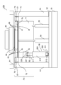
- Printing device 100 (FIG. 13, FIG. 14, FIG. 15)
- the configuration of the printing apparatus 100 will be described with reference to FIGS. 13, 14, and 15.
- a specific example of the printing device 100 is a screen printing device.
- the printing device 100 of the second embodiment does not have the gear 77, and the configuration of the drive unit 56 is different.
- the drive unit 56 has a link mechanism 30 that converts linear motion into rotary motion.
- the link mechanism 30 of the drive unit 56 has a crank mechanism 200.
- the drive unit 56 is arranged on the left side of the lower surface of the print table 70.
- the print table 70 has a receiving portion 220 fixed to the back surface of the rear flat portion 713.
- the receiving portion 220 has a bifurcated shape.
- the mobile table 52 has a clevis 230 fixed to the mobile table 52.
- the clevis 230 is located below the front flat portion 711.
- the clevis 230 has a bifurcated shape.
- the crank mechanism 200 has a receiving portion 220, a crank cylinder 210, a crankshaft 211, and a clevis 230.
- the crankshaft 211 is linearly moved on the central axis of the crank cylinder 210 by a linear servomotor.
- the upper end of the crankshaft 211 is rotatably attached to the receiving portion 220 by a pin 221.
- the pins 221 are orthogonal to the printing direction and are arranged horizontally.
- a cylinder joint 212 is fixed to the lower end of the crank cylinder 210.
- the cylinder joint 212 is rotatably attached to the clevis 230 by a pin 231.
- the pins 231 are orthogonal to the printing direction and are arranged horizontally.
- the upper end and the lower end of the crank mechanism 200 are rotatable, and the angle of intersection with the upper surface of the moving table 52 can be passively changed by the telescopic slide of the crankshaft 211.
- the crankshaft 211 rotates the printing table 70 around the center line C of the bent portion 992.
- the link mechanism 30 converts the linear motion of the crankshaft 211 into the rotational motion of the printing table 70 about the center line C of the bent portion 992.
- FIG. 16 is a diagram showing bending printing after the first half printing.
- the control unit 60 slides the crankshaft 211 to the upper left when printing the bent portion 992 of the work 99.
- the control unit 60 pushes up the receiving unit 220 upward by moving the crankshaft 211 forward to the upper left.
- the receiving portion 220 rotates clockwise around the rotation axis 75 (center line C), and rotates the printing table 70 clockwise around the rotation axis 75 (center line C).
- the cylinder joint 212 is rotatably attached to the moving table 52 by the clevis 230, when the receiving portion 220 is pushed upward, the tilt angle of the crank cylinder 210 with respect to the horizontal direction becomes large.
- the crankshaft 211 is rotatably attached to the printing table 70 by the receiving portion 220, when the receiving portion 220 is pushed upward, the tilt angle of the crankshaft 211 with respect to the horizontal direction becomes large.
- the printing table 70 is rotated by pushing up the printing table 70 with the crank mechanism 200.
- the arc length P to which the pin 221 moves is as follows.
- the control unit 60 moves the crankshaft 211 forward so that the pin 221 moves at a constant speed when the pin 221 moves along the arc length P.
- the pin 221 moves the arc length P, so that the bent portion 992 of the arc length E is printed. Will be done.
- the drive unit 56 is arranged so as to intersect the bent portion 992, but may be arranged only on the left side of the bent portion 992 or only on the right side of the bent portion 992.
- the drive unit 56 may be arranged in the center of the lower surface of the printing table 70 instead of the left side of the lower surface.
- Link mechanism 30 is not limited to the crank mechanism 200, and may be any mechanism that converts linear motion into rotational motion of the printing table centered on the center line C of the bent portion 992.
Abstract
印刷装置(100)は、印刷方向に対して平行な断面が円弧の屈曲部を有するワーク(99)を載置する印刷テーブル(70)と、前記屈曲部の中心線を中心にして前記印刷テーブル(70)を回転可能に取り付けた支柱(53)と、前記中心線を中心にして前記印刷テーブル(70)を回転させる駆動部(56)と、前記支柱(53)と前記駆動部(56)とを固定した移動台(52)と、前記移動台(52)を移動可能に取り付けた筐体(51)とを備えた。
Description
本発明は、印刷装置及び印刷方法に関するものである。
特にスクリーン印刷装置に関するものである。
特にスクリーン印刷装置に関するものである。
従来から、曲面を有するワークの印刷装置が考えられている。
本発明は、屈曲面を有するワークの印刷装置を提供する。
本発明の印刷装置は、
印刷方向に対して平行な垂直面による断面が円弧の屈曲部を有するワークを載置する印刷テーブルと、
前記屈曲部の中心線を中心にして前記印刷テーブルの回転軸を回転可能に取り付けた支柱と、
前記中心線を中心にして前記印刷テーブルを回転させる駆動部と、
前記支柱と前記駆動部とを固定した移動台と、
前記移動台を移動可能に取り付けた筐体と
を備えた。
印刷方向に対して平行な垂直面による断面が円弧の屈曲部を有するワークを載置する印刷テーブルと、
前記屈曲部の中心線を中心にして前記印刷テーブルの回転軸を回転可能に取り付けた支柱と、
前記中心線を中心にして前記印刷テーブルを回転させる駆動部と、
前記支柱と前記駆動部とを固定した移動台と、
前記移動台を移動可能に取り付けた筐体と
を備えた。
本発明によれば、屈曲面を有するワークに対して印刷をすることができる。
以上、本発明の実施の形態について、図を用いて説明する。
なお、各実施の形態の説明において、「上」、「下」、「左」、「右」、「前」、「後」、「表」、「裏」、「奥」、「高さ」、「幅」、「手前」、「縦」、「横」といった方向は、説明の便宜上、そのように記しているだけであって、装置、器具、部品等の配置又は向き等を限定するものではない。
なお、各実施の形態の説明において、「上」、「下」、「左」、「右」、「前」、「後」、「表」、「裏」、「奥」、「高さ」、「幅」、「手前」、「縦」、「横」といった方向は、説明の便宜上、そのように記しているだけであって、装置、器具、部品等の配置又は向き等を限定するものではない。
実施の形態1.
***ワーク99の説明***
●ワーク99(図4、図5)
ワーク99は、印刷方向に対して平行な垂直面による断面が円弧の屈曲部992を有する。
図4に示すように、ワーク99は、以下を有する。
●前平坦部991
●屈曲部992
●後平坦部993
***ワーク99の説明***
●ワーク99(図4、図5)
ワーク99は、印刷方向に対して平行な垂直面による断面が円弧の屈曲部992を有する。
図4に示すように、ワーク99は、以下を有する。
●前平坦部991
●屈曲部992
●後平坦部993
前平坦部991は、印刷の前半部分であり、平面を呈している部分である。
屈曲部992は、印刷の中央部分であり、屈曲している部分である。
後平坦部993は、印刷の後半部分であり、平面を呈している部分である。
屈曲部992は、印刷の中央部分であり、屈曲している部分である。
後平坦部993は、印刷の後半部分であり、平面を呈している部分である。
図5に示すように、屈曲部992の円弧の半径をRとする。
屈曲部992の円弧の中心を通る線を屈曲部992の中心線Cとする。
屈曲部992の円弧の内角をK度とする。
ワーク99の屈曲部992の円弧の内角がK度の場合、ワーク99の折り曲げ角度はK度となる。
すなわち、前平坦部991を水平に設置すると、後平坦部993は、水平からK度下方に傾く。
屈曲部992の円弧の中心を通る線を屈曲部992の中心線Cとする。
屈曲部992の円弧の内角をK度とする。
ワーク99の屈曲部992の円弧の内角がK度の場合、ワーク99の折り曲げ角度はK度となる。
すなわち、前平坦部991を水平に設置すると、後平坦部993は、水平からK度下方に傾く。
***印刷装置100の構成の説明***
●印刷装置100(図1、図2、図3)
図1と図2と図3に基づいて、印刷装置100の構成について説明する。
印刷装置100の具体例は、スクリーン印刷装置である。
図1において、紙面に向かって左右方向を横方向ともいう。
図1において、紙面に向かって上下方向を縦方向ともいう。
図1において、紙面に向かって奥行方向を幅方向ともいう。
図1において、印刷装置100の印刷方向は、左方向である。
●印刷装置100(図1、図2、図3)
図1と図2と図3に基づいて、印刷装置100の構成について説明する。
印刷装置100の具体例は、スクリーン印刷装置である。
図1において、紙面に向かって左右方向を横方向ともいう。
図1において、紙面に向かって上下方向を縦方向ともいう。
図1において、紙面に向かって奥行方向を幅方向ともいう。
図1において、印刷装置100の印刷方向は、左方向である。
印刷装置100は、印刷テーブル70に載置されたワーク99に対してスクリーン印刷をする。
印刷装置100は、スクリーン91を用いてスキージ92を用いてスクリーン印刷をする。
印刷装置100は、以下を有する。
●筐体51
●移動台52
●支柱53
●シリンダ54
●ストッパ55
●駆動部56
●制御部60
●印刷テーブル70
印刷装置100は、スクリーン91を用いてスキージ92を用いてスクリーン印刷をする。
印刷装置100は、以下を有する。
●筐体51
●移動台52
●支柱53
●シリンダ54
●ストッパ55
●駆動部56
●制御部60
●印刷テーブル70
●筐体51
筐体51は、印刷装置100の基台となるものである。
筐体51は、左右方向に長尺の矩形の金属板である。
筐体51は、水平に配置されている。
筐体51は、印刷装置100の基台となるものである。
筐体51は、左右方向に長尺の矩形の金属板である。
筐体51は、水平に配置されている。
●移動台52
移動台52は、筐体51に対して左右方向に移動可能に取り付けられている。
移動台52は、左右方向に長尺の矩形の金属板である。
移動台52は、以下を固定している。
(1)支柱53
(2)シリンダ54
(3)ストッパ55
(4)駆動部56
(5)制御部60
移動台52は、筐体51に対して左右方向に移動可能に取り付けられている。
移動台52は、左右方向に長尺の矩形の金属板である。
移動台52は、以下を固定している。
(1)支柱53
(2)シリンダ54
(3)ストッパ55
(4)駆動部56
(5)制御部60
●支柱53
支柱53は、移動台52の幅方向に1対設けられている。
支柱53は、移動台52に固定されている柱である。
支柱53は、ベークライト、又は、金属で製作する。
支柱53は、上部に印刷テーブル70を回転可能に取り付けている。
支柱53は、ワーク99の屈曲部992の中心線Cを中心にして印刷テーブル70を回転可能に取り付けている。
支柱53は、移動台52の幅方向に1対設けられている。
支柱53は、移動台52に固定されている柱である。
支柱53は、ベークライト、又は、金属で製作する。
支柱53は、上部に印刷テーブル70を回転可能に取り付けている。
支柱53は、ワーク99の屈曲部992の中心線Cを中心にして印刷テーブル70を回転可能に取り付けている。
●シリンダ54
シリンダ54は、左右方向に1対設けられ、移動台52に固定されている。
シリンダ54は、ロッドを上下に移動可能である。
ロッドの先端は、半球形状である。
シリンダ54は、印刷時に印刷テーブル70の下面を支持するものである。
左のシリンダ54は、印刷テーブル70の左側下面にあたり、印刷テーブル70の左側が水平になるように印刷テーブル70の左側下面を支える。
右のシリンダ54は、印刷テーブル70の右側下面にあたり、印刷テーブル70の右側が水平になるように印刷テーブル70の右側下面を支える。
シリンダ54は、左右方向に1対設けられ、移動台52に固定されている。
シリンダ54は、ロッドを上下に移動可能である。
ロッドの先端は、半球形状である。
シリンダ54は、印刷時に印刷テーブル70の下面を支持するものである。
左のシリンダ54は、印刷テーブル70の左側下面にあたり、印刷テーブル70の左側が水平になるように印刷テーブル70の左側下面を支える。
右のシリンダ54は、印刷テーブル70の右側下面にあたり、印刷テーブル70の右側が水平になるように印刷テーブル70の右側下面を支える。
●ストッパ55
ストッパ55は、左右方向に1対設けられ、移動台52に固定されている。
ストッパ55は、ロッドを上下の位置を調整可能である。
ロッドの先端は、半球形状である。
ストッパ55は、非印刷時に印刷テーブル70の下面を支持するものである。
左のストッパ55は、印刷テーブル70の左側下面にあたり、印刷テーブル70の左側が水平面より上に回転することを禁止する。
右のストッパ55は、印刷テーブル70の右側下面にあたり、印刷テーブル70の右側が水平面より上に回転することを禁止する。
ストッパ55は、左右方向に1対設けられ、移動台52に固定されている。
ストッパ55は、ロッドを上下の位置を調整可能である。
ロッドの先端は、半球形状である。
ストッパ55は、非印刷時に印刷テーブル70の下面を支持するものである。
左のストッパ55は、印刷テーブル70の左側下面にあたり、印刷テーブル70の左側が水平面より上に回転することを禁止する。
右のストッパ55は、印刷テーブル70の右側下面にあたり、印刷テーブル70の右側が水平面より上に回転することを禁止する。
●駆動部56
駆動部56は、ギア77を回転させ、印刷テーブルを回転させる。
駆動部56は、直線運動を回転運動に変換するリンク機構30を有する。
駆動部56のリンク機構30は、スライドテーブル561とラック562とを有する。
スライドテーブル561は、ラック562を左右方向にスライド可能に取り付けている。
ラック562の歯58は、ギア77の歯78と噛み合ってギア77を回転させる。
スライドテーブル561は、ラック562を左右に移動させることにより、屈曲部992の中心線Cを中心にして印刷テーブル70を回転させる。
リンク機構30は、ラック562の直線運動を屈曲部992の中心線Cを中心にした印刷テーブル70の回転運動に変換する。
●制御部60
制御部60は、印刷装置100を制御し、スクリーン印刷動作を制御する。
制御部60は、中央処理装置、プログラム、メモリ、及び、記憶装置により実現できる。
制御部60からの制御信号は、電気信号として信号線61により各部に伝達される。
以下に述べるスクリーン印刷動作は、制御部60が信号線61により命令及び信号を送受信することにより実現できる。
制御部60は、印刷装置100を制御し、スクリーン印刷動作を制御する。
制御部60は、中央処理装置、プログラム、メモリ、及び、記憶装置により実現できる。
制御部60からの制御信号は、電気信号として信号線61により各部に伝達される。
以下に述べるスクリーン印刷動作は、制御部60が信号線61により命令及び信号を送受信することにより実現できる。
●印刷テーブル70(図4と図5)
図4と図5を用いて、印刷テーブル70について説明する。
印刷テーブル70は、ワーク99を載置する。
印刷テーブル70は、回転軸75を中心にスイングする。
図4と図5を用いて、印刷テーブル70について説明する。
印刷テーブル70は、ワーク99を載置する。
印刷テーブル70は、回転軸75を中心にスイングする。
印刷テーブル70は、以下を有する。
(1)底板71
(2)ブラケット72
(3)前受け板73
(4)後受け板74
(5)隙間部76
(6)ギア77
(7)回転軸75
(1)底板71
(2)ブラケット72
(3)前受け板73
(4)後受け板74
(5)隙間部76
(6)ギア77
(7)回転軸75
●(1)底板71(図4)
底板71は、印刷テーブル70の形を決定する基礎材である。
底板71は、ステンレス、その他の金属で製作される。
底板71は、1枚の矩形の金属板を折り曲げて製作することができる。
底板71の折り曲げ角度(K度)は、ワーク99の折り曲げ角度(K度)と同じである。
底板71は、印刷テーブル70の形を決定する基礎材である。
底板71は、ステンレス、その他の金属で製作される。
底板71は、1枚の矩形の金属板を折り曲げて製作することができる。
底板71の折り曲げ角度(K度)は、ワーク99の折り曲げ角度(K度)と同じである。
図4に示すように、底板71は、以下を有する。
●前平部711
前平部711は、底板71の前半部分であり、平面を呈している部分である。
前平部711は、曲げ部712の途中までの長さを有する。
前平部711は、左端部がワーク99の屈曲部992の中心線Cの下まで存在している。
●曲げ部712
曲げ部712は、底板71の中央部分よりやや左よりの部分であり、屈曲している部分である。
曲げ部712は、ワーク99の屈曲部992と異なる半径で折り曲げられている。
曲げ部712は、ワーク99の屈曲部992と同じ半径Rで折り曲げられていてもよい。
●後平坦部993
後平部713は、底板71の後半部分であり、平面を呈している部分である。
●前平部711
前平部711は、底板71の前半部分であり、平面を呈している部分である。
前平部711は、曲げ部712の途中までの長さを有する。
前平部711は、左端部がワーク99の屈曲部992の中心線Cの下まで存在している。
●曲げ部712
曲げ部712は、底板71の中央部分よりやや左よりの部分であり、屈曲している部分である。
曲げ部712は、ワーク99の屈曲部992と異なる半径で折り曲げられている。
曲げ部712は、ワーク99の屈曲部992と同じ半径Rで折り曲げられていてもよい。
●後平坦部993
後平部713は、底板71の後半部分であり、平面を呈している部分である。
●(2)ブラケット72(図4)
ブラケット72は、印刷テーブル70の幅方向に1対設けられている。
ブラケット72は、柱状の六面体の棒である。
ブラケット72は、アルミニウム、その他の金属で製作される。
ブラケット72は、印刷テーブル70(前受け板73)の両側にネジ81(図5)で固定されている。
ブラケット72は、前平部711の右端から曲げ部712の途中までの長さを有する。
ブラケット72は、前平部711と同じ長さを有している。
ブラケット72は、左端部がワーク99の屈曲部992の中心線Cをカバーしている。
ブラケット72は、左端の上部に、回転軸75を取り付けている。
ブラケット72は、屈曲部992の中心線Cとなる位置に、回転軸75を取り付けている。
●(3)前受け板73(図4)
前受け板73は、六面体の板である。
前受け板73は、ベークライト、プラスチック、その他の樹脂、又は、金属で製作される。
前受け板73は、前平部711の上面にネジ83(図5)で固定されている。
前受け板73は、前平部711の長さ以下の長さを有する。
前受け板73は、上面にワーク99の前平坦部991を載置する。
前受け板73は、1対のブラケット72を幅方向に連結する連結板である。
前受け板73は、六面体の板である。
前受け板73は、ベークライト、プラスチック、その他の樹脂、又は、金属で製作される。
前受け板73は、前平部711の上面にネジ83(図5)で固定されている。
前受け板73は、前平部711の長さ以下の長さを有する。
前受け板73は、上面にワーク99の前平坦部991を載置する。
前受け板73は、1対のブラケット72を幅方向に連結する連結板である。
●(4)後受け板74(図4)
後受け板74は、六面体の板である。
後受け板74は、ベークライト、プラスチック、その他の樹脂、又は、金属で製作される。
後受け板74は、後平部713の上面にネジ83(図5)で固定されている。
後受け板74は、後平部713の長さ以下の長さを有する。
後受け板74は、上面にワーク99の後平坦部993を載置する。
前平部711が曲げ部712の途中までの長さを有するので、後受け板74は、前受け板73より薄くなっている。
後受け板74は、六面体の板である。
後受け板74は、ベークライト、プラスチック、その他の樹脂、又は、金属で製作される。
後受け板74は、後平部713の上面にネジ83(図5)で固定されている。
後受け板74は、後平部713の長さ以下の長さを有する。
後受け板74は、上面にワーク99の後平坦部993を載置する。
前平部711が曲げ部712の途中までの長さを有するので、後受け板74は、前受け板73より薄くなっている。
●(5)隙間部76(図5)
隙間部76は、前受け板73の左端面と後受け板74の右端面との間にある空間である。
隙間部76の上には、ワーク99の屈曲部992が配置される。
隙間部76は、前受け板73の左端面と後受け板74の右端面との間にある空間である。
隙間部76の上には、ワーク99の屈曲部992が配置される。
●(6)ギア77(図5)
ギア77は、印刷テーブル70の片側に1個設けられている。
ギア77は、印刷テーブル70の回転軸75を回転させる。
ギア77は、印刷テーブル70のブラケット72にネジ82で固定されている。
ギア77は、扇形状をしている。
ギア77は、回転軸75を中心にして回転する。
ギア77が回転すれば、印刷テーブル70も回転する。
ギア77の内角は、L度であり、L度は折り曲げ角度K度以上であればよい。
ギア77の半径Mは、ワーク99の屈曲部992の中心線C(図5)を中心としている。
ギア77の半径Mは、ワーク99の屈曲部992の半径Rよりも大きい。
ギア77の歯78は、半径Mの円弧に沿って配置されている。
ギア77は、印刷テーブル70の片側に1個設けられている。
ギア77は、印刷テーブル70の回転軸75を回転させる。
ギア77は、印刷テーブル70のブラケット72にネジ82で固定されている。
ギア77は、扇形状をしている。
ギア77は、回転軸75を中心にして回転する。
ギア77が回転すれば、印刷テーブル70も回転する。
ギア77の内角は、L度であり、L度は折り曲げ角度K度以上であればよい。
ギア77の半径Mは、ワーク99の屈曲部992の中心線C(図5)を中心としている。
ギア77の半径Mは、ワーク99の屈曲部992の半径Rよりも大きい。
ギア77の歯78は、半径Mの円弧に沿って配置されている。
●(7)回転軸75(図4)
回転軸75は、印刷テーブル70の幅方向に1対設けられている。
回転軸75は、一直線状に存在する。
回転軸75は、印刷テーブル70を幅方向に貫通した1本の軸でもよい。
回転軸75は、印刷方向と直交して配置され、水平に配置されている。
回転軸75は、支柱533に固定されているシャフトである。
回転軸75は、ギア77とブラケット72とを貫通している。
回転軸75は、ギア77とブラケット72とを回転可能に取り付けている。
回転軸75の中心線は、屈曲部992の中心線Cと一致している。
回転軸75は、印刷テーブル70の幅方向に1対設けられている。
回転軸75は、一直線状に存在する。
回転軸75は、印刷テーブル70を幅方向に貫通した1本の軸でもよい。
回転軸75は、印刷方向と直交して配置され、水平に配置されている。
回転軸75は、支柱533に固定されているシャフトである。
回転軸75は、ギア77とブラケット72とを貫通している。
回転軸75は、ギア77とブラケット72とを回転可能に取り付けている。
回転軸75の中心線は、屈曲部992の中心線Cと一致している。
***動作の説明***
図6を用いて、ワーク99を載置した印刷テーブル70を回転可能に取り付けた印刷装置100のスクリーン印刷方法について説明する。
ここでは、前平坦部991と屈曲部992と後平坦部993とを有するワーク99を印刷する方法について説明する。
また、印刷装置100の左方向への印刷動作について説明する。
図6を用いて、ワーク99を載置した印刷テーブル70を回転可能に取り付けた印刷装置100のスクリーン印刷方法について説明する。
ここでは、前平坦部991と屈曲部992と後平坦部993とを有するワーク99を印刷する方法について説明する。
また、印刷装置100の左方向への印刷動作について説明する。
*準備工程S10*
印刷装置100の電源がオンになると、制御部60は、以下の初期動作を開始する。
制御部60は、スライドテーブル561のラック562を右側の初期位置に移動させて、印刷テーブル70を、図7に示すように、前半部が水平になるように回転させる。
左のストッパ55は、印刷テーブル70が左に大きく回転すること禁止する。
制御部60は、図示していない搬出入装置により、ワーク99を印刷テーブル70に載せ、ワーク99をスクリーン91の下に配置する。
制御部60は、図示していない吸引機構によりワーク99を印刷テーブル70に吸引しワーク99を印刷テーブル70に固定する。
制御部60は、右のシリンダ54のロッドを上昇させる。
右のシリンダ54はワーク99の前平坦部991がスクリーン91と平行になった状態で、前平部711の下面を支持する。
制御部60は、スキージ92を右側の印刷開始位置に移動させる。
*前半印刷工程S20*
図7は、前半印刷を示す図である。
前半印刷工程S20は、ワーク99の前平坦部991が載置された印刷テーブル70の前半部を印刷方向と平行に固定して、前平坦部991を印刷する工程である。
制御部60は、スキージ92の左方向への移動を開始して印刷を開始する。
前半印刷中、制御部60は、スライドテーブル561をロックし、印刷テーブル70の回転を禁止する。
前半印刷中、制御部60は、移動台52の移動を停止する。
前半印刷中、右のシリンダ54が、前平部711の下面を支持しているので、前平坦部991に印刷圧力がかかっても印刷テーブル70が右回転したり、印刷テーブル70が変形することはない。
前半印刷工程S20は、ワーク99の前平坦部991を印刷した時点で終了する。
*屈曲印刷工程S30*
図8は、前半印刷後の屈曲印刷を示す図である。
屈曲印刷工程S30は、ワーク99の屈曲部992の中心線Cを中心にして印刷テーブル70を回転させながら、かつ、印刷テーブル70を印刷方向に移動させながら、屈曲部992を印刷する工程である。
制御部60は、ワーク99の屈曲部992を印刷する場合、同時に以下の制御をする。
(1)スライドテーブル561のラック562を左にスライドする。ラック562を移動させることにより、ギア77を回転させ、回転軸75(中心線C)を中心に印刷テーブル70を回転させる。
(2)筐体51に対して移動台52を左方向(印刷方向)に移動させる。
(3)スキージ92の左方向(印刷方向)への移動を継続する。
(4)右側のシリンダ54のロッドを下降させる。
(5)左側のシリンダ54のロッドを上昇させる。
屈曲印刷工程S30では、屈曲部992の半径Rよりも大きい半径Lを有するギア77を回転させることにより印刷テーブル70を回転させる。
屈曲部992の下面は隙間部76であるが、屈曲部992に印刷圧力がかかっても屈曲部992が凸曲面を呈しているので、屈曲部992が変形することはない。
屈曲印刷工程S30は、ワーク99の屈曲部992を印刷した時点で終了する。
*後半印刷工程S40*
図9は、屈曲印刷後の後半印刷工程を示す図である。
後半印刷工程S40は、ワーク99の後平坦部993が載置された印刷テーブル70の後半部を印刷方向と平行に固定して、後平坦部993を印刷する工程である。
制御部60は、スキージ92の左方向への移動を継続する。
後半印刷中、制御部60は、スライドテーブル561をロックし、印刷テーブル70の回転を禁止する。
後半印刷中、制御部60は、移動台52の移動を停止する。
後半印刷中、左側のシリンダ54が、後平部713の下面を支持しているので、印刷圧力がかかっても印刷テーブル70が左回転することがなく、印刷テーブル70が変形することもない。
後半印刷工程S40は、ワーク99の後平坦部993を印刷した時点で終了する。
印刷が終了すると、制御部60は、図示していない搬出入装置により、印刷が終了したワーク99を搬出する。
制御部60は、ワーク99の搬出後、次の印刷があるか判断し、次の印刷がある場合、準備工程S10に戻る。
制御部60は、次の印刷がなければ、印刷を終了する。
制御部60は、ワーク99の搬出後、次の印刷があるか判断し、次の印刷がある場合、準備工程S10に戻る。
制御部60は、次の印刷がなければ、印刷を終了する。
●屈曲印刷工程S30における制御
図5を用いて、屈曲印刷工程S30の詳細について説明する。
屈曲部992の円弧の半径がRであり、内角がK度の場合、屈曲部992の円弧長Eは以下のようになる。
円弧長E=直径*円周率*円周に対する円弧の比
=(2*半径R)*3.14*(K度÷360度)
具体例として、半径R=5mm、K度=35度の場合、屈曲部992の円弧長Eは以下のようになる。
円弧長E=(2*5mm)*3.14*(35度÷360度)
=10*3.14*35÷360
=3.05277
≒3.05mm
制御部60は、具体的には以下の制御をする。
(1)ギア77を35度だけ時計周りに回転させるようにスライドテーブル561のラック562を左にスライドさせる。ギア77を35度だけ時計周りに回転させることにより回転軸75を中心に印刷テーブル70を35度だけ時計周りに回転させる。
(2)筐体51に対して移動台52を左方向(印刷方向)に3.05mm移動させる。
(3)スキージ92を左方向(印刷方向)へ3.05mm移動させる。
***実施の形態1の効果の説明***
従来の曲面印刷機構は、なだらかな曲面に対するものであり、小さな半径を有する曲面の印刷には向いていない場合がある。
実施の形態1によれば、小さな半径の円弧を有する屈曲部に対して印刷することができる。
実施の形態1によれば、ギア77の半径Mがワーク99の屈曲部992の半径Rよりも大きいので、精度の高い回転をさせることができる。
実施の形態1によれば、折り曲げ角度がワーク99の折り曲げ角度と同じ底板71のみ制作することにより、印刷テーブル70の他の部品と共用することができる。
従来の曲面印刷機構は、なだらかな曲面に対するものであり、小さな半径を有する曲面の印刷には向いていない場合がある。
実施の形態1によれば、小さな半径の円弧を有する屈曲部に対して印刷することができる。
実施の形態1によれば、ギア77の半径Mがワーク99の屈曲部992の半径Rよりも大きいので、精度の高い回転をさせることができる。
実施の形態1によれば、折り曲げ角度がワーク99の折り曲げ角度と同じ底板71のみ制作することにより、印刷テーブル70の他の部品と共用することができる。
***実施の形態1の変形例1***
●駆動部56、シリンダ54、ストッパ55の変形例(図10)
図10に示す駆動部56は、モータ563とギア564とを有する。
制御部60は、モータ563によりギア564を回転させ、印刷テーブル70を回転させることができる。ギア564は扇形でなくてもよく、円形又は半円形でもよい。
図10に示すシリンダ54とストッパ55とは、横向きに配置されている。
シリンダ54とストッパ55とが横向きに配置されることにより、移動台52の上空が空き、印刷テーブル70の回転角度を拡大することができる。
なお、シリンダ54とストッパ55とを1つのシリンダで兼用してもよい。
また、ギア77と駆動部56とによる印刷テーブル70の固定が印刷圧力に抗することができるほど強固であれば、シリンダ54は不要である。
***実施の形態1の変形例2***
●印刷テーブル70の変形例(図11)
図11に示す印刷テーブル70は、前受け板73と後受け板74とがなく、底板71とブラケット72とを有する。
ブラケット72は、立方体形状であり、中央に回転軸75を貫通させる貫通孔を有する。
ブラケット72は、底板71の曲げ部712の両サイドに、図示していないネジにより固定される。
底板71の前平部711は、ワーク99の前平坦部991を下から支持する。
底板71の曲げ部712は、ワーク99の屈曲部992と同じ円弧を有する。
底板71の曲げ部712は、ワーク99の屈曲部992を下から支持する。
底板71の後平部713は、ワーク99の後平坦部993を下から支持する。
***実施の形態1の変形例3***
●印刷テーブル70とワーク99の変形例(図12)
ギア77も扇形でなくてもよく、円形又は半円形でもよい。
図12の(a)と(b)は折り曲げ角度が90度の図である。
ギア77の内角は、90度以上必要である。
●印刷テーブル70とワーク99の変形例(図12)
ギア77も扇形でなくてもよく、円形又は半円形でもよい。
図12の(a)と(b)は折り曲げ角度が90度の図である。
ギア77の内角は、90度以上必要である。
図12の(a)のように、ワーク99は、前平坦部991と屈曲部992のみがあり後平坦部993がなくてもよい。
図12の(b)のように、ワーク99は、前平坦部991がなく、屈曲部992と後平坦部993のみがあってもよい。
図12の(c)は、ワーク99が屈曲部992のみの図である。
ワーク99は、屈曲部992が印刷テーブル70により吸引されて印刷テーブル70に固定されている。
ワーク99は、屈曲部992が印刷テーブル70により吸引されて印刷テーブル70に固定されている。
図12の(d)は、屈曲部992の内角と折り曲げ角度とが180度の図である。
ワーク99と印刷テーブル70とは、U字状に折れ曲がっている。
ギア77の内角は、180度以上必要である。
ワーク99と印刷テーブル70とは、U字状に折れ曲がっている。
ギア77の内角は、180度以上必要である。
実施の形態2.
実施の形態2では、実施の形態1と異なる点について説明する。
実施の形態2では、実施の形態1と異なる点について説明する。
***印刷装置100の構成の説明***
●印刷装置100(図13、図14、図15)
図13と図14と図15に基づいて、印刷装置100の構成について説明する。
印刷装置100の具体例は、スクリーン印刷装置である。
実施の形態2の印刷装置100は、ギア77がなく、駆動部56の構成が異なる。
●印刷装置100(図13、図14、図15)
図13と図14と図15に基づいて、印刷装置100の構成について説明する。
印刷装置100の具体例は、スクリーン印刷装置である。
実施の形態2の印刷装置100は、ギア77がなく、駆動部56の構成が異なる。
●駆動部56
駆動部56は、直線運動を回転運動に変換するリンク機構30を有する。
駆動部56のリンク機構30は、クランク機構200を有する。
図14において、駆動部56は、印刷テーブル70の下面の左側に配置されている。
印刷テーブル70は、後平部713の裏面に固定された受け部220を有する。
受け部220は、二山形状をしている。
移動台52は、移動台52に固定されたクレビス230を有する。
クレビス230は、前平部711の下方に配置されている。
クレビス230は、二山形状をしている。
駆動部56は、直線運動を回転運動に変換するリンク機構30を有する。
駆動部56のリンク機構30は、クランク機構200を有する。
図14において、駆動部56は、印刷テーブル70の下面の左側に配置されている。
印刷テーブル70は、後平部713の裏面に固定された受け部220を有する。
受け部220は、二山形状をしている。
移動台52は、移動台52に固定されたクレビス230を有する。
クレビス230は、前平部711の下方に配置されている。
クレビス230は、二山形状をしている。
●クランク機構200
クランク機構200は、受け部220とクランクシリンダ210とクランクシャフト211とクレビス230を有する。
クランクシャフト211は、リニアサーボモータによりクランクシリンダ210の中心軸において直線移動する。
クランクシャフト211の上端は、ピン221により受け部220に回転可能に取り付けられている。ピン221は、印刷方向と直交しており水平に配置されている。
クランクシリンダ210の下端には、シリンダジョイント212が固定されている。
シリンダジョイント212は、ピン231によりクレビス230に回転可能に取り付けられている。ピン231は、印刷方向と直交しており水平に配置されている。
クランク機構200は、上端と下端とが回転可能であり、クランクシャフト211の伸縮スライドにより、移動台52の上面と交わる角度を、受動的に変更することができる。
クランクシャフト211は、受け部220を押すことにより、屈曲部992の中心線Cを中心にして印刷テーブル70を回転させる。
リンク機構30は、クランクシャフト211の直線運動を屈曲部992の中心線Cを中心にした印刷テーブル70の回転運動に変換する。
***動作の説明***
図16により、屈曲印刷工程S30について説明する。*屈曲印刷工程S30*
図16は、前半印刷後の屈曲印刷を示す図である。
制御部60は、ワーク99の屈曲部992を印刷する場合、クランクシャフト211を左上にスライドする。
制御部60は、クランクシャフト211を左上に前進移動させることにより、受け部220を上方に押し上げる。
受け部220は、回転軸75(中心線C)を中心に時計回り方向に回転し、回転軸75(中心線C)を中心に印刷テーブル70を時計回り方向に回転させる。
シリンダジョイント212は、クレビス230により移動台52に対して回転可能に取り付けられているので、受け部220が上方に押し上げられると、クランクシリンダ210の水平方向に対する傾き角度が大きくなる。
クランクシャフト211は、受け部220により印刷テーブル70に対して回転可能に取り付けられているので、受け部220が上方に押し上げられると、クランクシャフト211の水平方向に対する傾き角度が大きくなる。
屈曲印刷工程S30では、印刷テーブル70をクランク機構200で押し上げることにより印刷テーブル70を回転させる。
受け部220のピン221と中心軸Cとの距離をLとし、印刷テーブル70をK度回転させる場合、ピン221が移動する円弧長Pは以下のようになる。
円弧長P=直径*円周率*円周に対する円弧の比
=(2*半径L)*3.14*(K度÷360度)
制御部60は、ピン221が円弧長Pを移動する際に、ピン221が等速で移動するようにクランクシャフト211を前進移動させる。
実施の形態1で述べたように、屈曲部992の円弧の半径がRであり、内角がK度の場合、ピン221が円弧長Pを移動することにより、円弧長Eの屈曲部992が印刷される。
円弧長P=直径*円周率*円周に対する円弧の比
=(2*半径L)*3.14*(K度÷360度)
制御部60は、ピン221が円弧長Pを移動する際に、ピン221が等速で移動するようにクランクシャフト211を前進移動させる。
実施の形態1で述べたように、屈曲部992の円弧の半径がRであり、内角がK度の場合、ピン221が円弧長Pを移動することにより、円弧長Eの屈曲部992が印刷される。
***実施の形態2の変形例1***
●駆動部56の配置
図13において、駆動部56は、屈曲部992と交差して配置されているが、屈曲部992の左側のみ、又は、屈曲部992の右側のみに配置されてもよい。
図14において、駆動部56は、印刷テーブル70の下面の左側ではなく下面中央に配置されてもよい。
●駆動部56の配置
図13において、駆動部56は、屈曲部992と交差して配置されているが、屈曲部992の左側のみ、又は、屈曲部992の右側のみに配置されてもよい。
図14において、駆動部56は、印刷テーブル70の下面の左側ではなく下面中央に配置されてもよい。
***実施の形態2の変形例2***
●リンク機構30
リンク機構30は、クランク機構200に限らず、直線運動を屈曲部992の中心線Cを中心にした印刷テーブルの回転運動に変換する機構であればよい。
●リンク機構30
リンク機構30は、クランク機構200に限らず、直線運動を屈曲部992の中心線Cを中心にした印刷テーブルの回転運動に変換する機構であればよい。
以上、本発明の実施の形態と変形例について説明したが、これらの実施の形態と変形例のうち、2つ以上を組み合わせて実施しても構わない。あるいは、これらの実施の形態と変形例のうち、1つを部分的に実施しても構わない。あるいは、これらの実施の形態と変形例のうち、2つ以上を部分的に組み合わせて実施しても構わない。なお、本発明は、これらの実施の形態と変形例に限定されるものではなく、必要に応じて種々の変更が可能である。
30 リンク機構、51 筐体、52 移動台、53 支柱、54 シリンダ、55 ストッパ、56 駆動部、561 スライドテーブル、562 ラック、563 モータ、564 ギア、58 歯、60 制御部、61 信号線、70 印刷テーブル、71 底板、711 前平部、712 曲げ部、713 後平部、72 ブラケット、73 前受け板、74 後受け板、75 回転軸、76 隙間部、77 ギア、78 歯、81 ネジ、82 ネジ、83 ネジ、91 スクリーン、92 スキージ、99 ワーク、991 前平坦部、992 屈曲部、993 後平坦部、100 印刷装置、200 クランク機構、210 クランクシリンダ、211 クランクシャフト、212 シリンダジョイント、220 受け部、221 ピン、230 クレビス、231 ピン。
Claims (13)
- 印刷方向に対して平行な垂直面による断面が円弧の屈曲部を有するワークを載置する印刷テーブルと、
前記屈曲部の中心線を中心にして前記印刷テーブルの回転軸を回転可能に取り付けた支柱と、
前記中心線を中心にして前記印刷テーブルを回転させる駆動部と、
前記支柱と前記駆動部とを固定した移動台と、
前記移動台を移動可能に取り付けた筐体と
を備えた印刷装置。 - 前記駆動部は、直線運動を前記屈曲部の中心線を中心にした前記印刷テーブルの回転運動に変換するリンク機構を有する請求項1に記載の印刷装置。
- 前記印刷テーブルは、
前記印刷テーブルの前記回転軸を回転させる扇形状のギアを有し、
前記駆動部は、前記ギアの歯と噛み合って前記ギアを回転させる請求項1又は2に記載の印刷装置。 - 前記ギアの半径は、前記屈曲部の半径よりも大きい請求項3に記載の印刷装置。
- 前記印刷テーブルは、裏面に固定された受け部を有し、
前記駆動部は、前記受け部に回転可能に取り付けられたクランク機構を有する請求項1又は2に記載の印刷装置。 - 前記クランク機構は、クランクシャフトとクランクシリンダとを有し、
前記クランクシャフトの上端は、前記受け部に回転可能に取り付けられ、
前記クランクシリンダの下端は、前記移動台に回転可能に取り付けられている請求項5に記載の印刷装置。 - 前記印刷テーブルは、
両側に固定されたブラケットを有し、
前記ブラケットは、前記屈曲部の中心線となる位置に、前記回転軸を取り付けている請求項1から6のいずれか1項に記載の印刷装置。 - 前記印刷テーブルは、
前平部と曲げ部と後平部とを有する板状の底板と、
前記前平部に固定された前受け板と、
前記後平部に固定された後受け板と
を有し、
前記前受け板と前記後受け板との間に隙間部がある請求項1から7のいずれか1項に記載の印刷装置。 - 前記移動台に固定され、前記印刷テーブルを支持するシリンダを備えた請求項1から8のいずれか1項に記載の印刷装置。
- 印刷動作を制御する制御部を備え、
前記制御部は、前記ワークの屈曲部を印刷する場合、前記駆動部により前記中心線を中心に前記印刷テーブルを回転させながら前記移動台を印刷方向に移動させる請求項1から9のいずれか1項に記載の印刷装置。 - 前平坦部と屈曲部と後平坦部とを有するワークを載置した印刷テーブルを回転可能に取り付けた印刷装置の印刷方法において、
ワークの前平坦部が載置された印刷テーブルの前半部を印刷方向と平行に固定して前記前平坦部を印刷する前半印刷工程と、
ワークの屈曲部の中心線を中心にして印刷テーブルを回転させながら、かつ、印刷テーブルを印刷方向に移動させながら、前記屈曲部を印刷する屈曲印刷工程と、
ワークの後平坦部が載置された印刷テーブルの後半部を印刷方向と平行に固定して前記後平坦部を印刷する後半印刷工程と
を備えた印刷方法。 - 前記屈曲印刷工程は、前記屈曲部の半径よりも大きい半径を有するギアを、前記屈曲部の前記中心線に対して回転軸を一致させて回転させることにより前記印刷テーブルを回転させる請求項11に記載の印刷方法。
- 前記屈曲印刷工程は、前記印刷テーブルをクランク機構で押し上げることにより前記印刷テーブルを回転させる請求項11に記載の印刷方法。
Priority Applications (4)
| Application Number | Priority Date | Filing Date | Title |
|---|---|---|---|
| CN202080101568.6A CN115666950A (zh) | 2020-06-17 | 2020-06-17 | 印刷装置及印刷方法 |
| JP2022531166A JP7273448B2 (ja) | 2020-06-17 | 2020-06-17 | 印刷装置及び印刷方法 |
| PCT/JP2020/023745 WO2021255854A1 (ja) | 2020-06-17 | 2020-06-17 | 印刷装置及び印刷方法 |
| TW109129682A TWI792050B (zh) | 2020-06-17 | 2020-08-31 | 印刷裝置及印刷方法 |
Applications Claiming Priority (1)
| Application Number | Priority Date | Filing Date | Title |
|---|---|---|---|
| PCT/JP2020/023745 WO2021255854A1 (ja) | 2020-06-17 | 2020-06-17 | 印刷装置及び印刷方法 |
Publications (1)
| Publication Number | Publication Date |
|---|---|
| WO2021255854A1 true WO2021255854A1 (ja) | 2021-12-23 |
Family
ID=79268713
Family Applications (1)
| Application Number | Title | Priority Date | Filing Date |
|---|---|---|---|
| PCT/JP2020/023745 WO2021255854A1 (ja) | 2020-06-17 | 2020-06-17 | 印刷装置及び印刷方法 |
Country Status (4)
| Country | Link |
|---|---|
| JP (1) | JP7273448B2 (ja) |
| CN (1) | CN115666950A (ja) |
| TW (1) | TWI792050B (ja) |
| WO (1) | WO2021255854A1 (ja) |
Citations (8)
| Publication number | Priority date | Publication date | Assignee | Title |
|---|---|---|---|---|
| JPH01178499A (ja) * | 1988-01-11 | 1989-07-14 | Koito Mfg Co Ltd | 曲面印刷方法及び曲面印刷装置 |
| JPH0395236U (ja) * | 1990-01-18 | 1991-09-27 | ||
| JPH05254087A (ja) * | 1992-03-14 | 1993-10-05 | Taiyo Yuden Co Ltd | グリーンシートのパターン印刷方法及び装置 |
| KR100826216B1 (ko) * | 2006-12-26 | 2008-04-30 | 장도영 | 원추형 인쇄물 스크린 인쇄장치 |
| WO2017086137A1 (ja) * | 2015-11-18 | 2017-05-26 | 旭硝子株式会社 | 印刷版、印刷装置、基材及び基材の製造方法 |
| WO2017086197A1 (ja) * | 2015-11-18 | 2017-05-26 | 旭硝子株式会社 | 曲面スクリーン印刷装置、曲面スクリーン印刷方法、及び印刷層を有する基材の製造方法 |
| JP2017094718A (ja) * | 2015-11-18 | 2017-06-01 | 旭硝子株式会社 | スクリーン印刷方法及びスクリーン印刷装置、並びに印刷層付き基材の製造方法及び基材 |
| JP2017209982A (ja) * | 2016-04-04 | 2017-11-30 | マイクロ・テック株式会社 | ワーク操作装置、ワーク操作方法、曲面治具、曲面治具の製造方法及びスクリーン印刷装置 |
Family Cites Families (4)
| Publication number | Priority date | Publication date | Assignee | Title |
|---|---|---|---|---|
| JP4650426B2 (ja) | 2005-01-17 | 2011-03-16 | 株式会社村田製作所 | スクリーン印刷装置およびスクリーン印刷方法 |
| JP6767181B2 (ja) | 2016-06-30 | 2020-10-14 | 株式会社セリアエンジニアリング | スクリーン印刷機 |
| JP7054131B2 (ja) * | 2017-08-10 | 2022-04-13 | マイクロ・テック株式会社 | スクリーン印刷装置及びスクリーン印刷方法 |
| CN210126344U (zh) * | 2019-02-15 | 2020-03-06 | 佛山市力美照明科技股份有限公司 | 一种用于灯泡的丝印机 |
-
2020
- 2020-06-17 WO PCT/JP2020/023745 patent/WO2021255854A1/ja active Application Filing
- 2020-06-17 CN CN202080101568.6A patent/CN115666950A/zh active Pending
- 2020-06-17 JP JP2022531166A patent/JP7273448B2/ja active Active
- 2020-08-31 TW TW109129682A patent/TWI792050B/zh active
Patent Citations (8)
| Publication number | Priority date | Publication date | Assignee | Title |
|---|---|---|---|---|
| JPH01178499A (ja) * | 1988-01-11 | 1989-07-14 | Koito Mfg Co Ltd | 曲面印刷方法及び曲面印刷装置 |
| JPH0395236U (ja) * | 1990-01-18 | 1991-09-27 | ||
| JPH05254087A (ja) * | 1992-03-14 | 1993-10-05 | Taiyo Yuden Co Ltd | グリーンシートのパターン印刷方法及び装置 |
| KR100826216B1 (ko) * | 2006-12-26 | 2008-04-30 | 장도영 | 원추형 인쇄물 스크린 인쇄장치 |
| WO2017086137A1 (ja) * | 2015-11-18 | 2017-05-26 | 旭硝子株式会社 | 印刷版、印刷装置、基材及び基材の製造方法 |
| WO2017086197A1 (ja) * | 2015-11-18 | 2017-05-26 | 旭硝子株式会社 | 曲面スクリーン印刷装置、曲面スクリーン印刷方法、及び印刷層を有する基材の製造方法 |
| JP2017094718A (ja) * | 2015-11-18 | 2017-06-01 | 旭硝子株式会社 | スクリーン印刷方法及びスクリーン印刷装置、並びに印刷層付き基材の製造方法及び基材 |
| JP2017209982A (ja) * | 2016-04-04 | 2017-11-30 | マイクロ・テック株式会社 | ワーク操作装置、ワーク操作方法、曲面治具、曲面治具の製造方法及びスクリーン印刷装置 |
Also Published As
| Publication number | Publication date |
|---|---|
| TW202200400A (zh) | 2022-01-01 |
| JP7273448B2 (ja) | 2023-05-15 |
| CN115666950A (zh) | 2023-01-31 |
| JPWO2021255854A1 (ja) | 2021-12-23 |
| TWI792050B (zh) | 2023-02-11 |
Similar Documents
| Publication | Publication Date | Title |
|---|---|---|
| TW201517997A (zh) | 零件分選機構及分選方法、零件供應系統 | |
| JP5557007B2 (ja) | 作業台 | |
| WO2021255854A1 (ja) | 印刷装置及び印刷方法 | |
| JPH0839767A (ja) | スクリーン印刷装置 | |
| JP2007015072A (ja) | 自動回転ステージ | |
| CN101472394B (zh) | 对位装置 | |
| JP6892560B2 (ja) | クランプレールユニット | |
| CN214269218U (zh) | 一种翻转机构 | |
| JP7218963B2 (ja) | スイングテーブル、テーブルスイング方法、及び、スクリーン印刷装置 | |
| JPH08114257A (ja) | 円弧運動機構 | |
| JP5610937B2 (ja) | 傾斜回転鍛造装置 | |
| JP2969624B2 (ja) | 平行移動装置 | |
| JPH10315035A (ja) | 板材の剪断機 | |
| JPH056124Y2 (ja) | ||
| WO2022013999A1 (ja) | スクリーン印刷装置及びスクリーン印刷方法 | |
| JPH0550293A (ja) | 回転溶接装置 | |
| JPH04266426A (ja) | 曲げ加工装置 | |
| JP2023018391A (ja) | スクリーン印刷装置及びスクリーン印刷方法 | |
| JPH01107924A (ja) | 板金部材のヘミング加工装置 | |
| KR101547068B1 (ko) | 스크린 프린터 | |
| CN216758790U (zh) | 旋转定位组件及调姿定位装置 | |
| JPH0699325A (ja) | 自動調整検査装置 | |
| JP2003181686A (ja) | ワーク位置決め装置 | |
| JP3509638B2 (ja) | 基板の回転位置決め装置 | |
| JPH0641696Y2 (ja) | 板材加工機におけるクランプ装置 |
Legal Events
| Date | Code | Title | Description |
|---|---|---|---|
| 121 | Ep: the epo has been informed by wipo that ep was designated in this application |
Ref document number: 20941395 Country of ref document: EP Kind code of ref document: A1 |
|
| ENP | Entry into the national phase |
Ref document number: 2022531166 Country of ref document: JP Kind code of ref document: A |
|
| NENP | Non-entry into the national phase |
Ref country code: DE |
|
| 122 | Ep: pct application non-entry in european phase |
Ref document number: 20941395 Country of ref document: EP Kind code of ref document: A1 |