WO2021250790A1 - Stator pour machine électrique tournante - Google Patents
Stator pour machine électrique tournante Download PDFInfo
- Publication number
- WO2021250790A1 WO2021250790A1 PCT/JP2020/022741 JP2020022741W WO2021250790A1 WO 2021250790 A1 WO2021250790 A1 WO 2021250790A1 JP 2020022741 W JP2020022741 W JP 2020022741W WO 2021250790 A1 WO2021250790 A1 WO 2021250790A1
- Authority
- WO
- WIPO (PCT)
- Prior art keywords
- segment
- linear
- linear portion
- section
- coil
- Prior art date
Links
Images


Classifications
-
- H—ELECTRICITY
- H02—GENERATION; CONVERSION OR DISTRIBUTION OF ELECTRIC POWER
- H02K—DYNAMO-ELECTRIC MACHINES
- H02K3/00—Details of windings
- H02K3/04—Windings characterised by the conductor shape, form or construction, e.g. with bar conductors
- H02K3/12—Windings characterised by the conductor shape, form or construction, e.g. with bar conductors arranged in slots
-
- H—ELECTRICITY
- H02—GENERATION; CONVERSION OR DISTRIBUTION OF ELECTRIC POWER
- H02K—DYNAMO-ELECTRIC MACHINES
- H02K1/00—Details of the magnetic circuit
- H02K1/06—Details of the magnetic circuit characterised by the shape, form or construction
- H02K1/12—Stationary parts of the magnetic circuit
- H02K1/16—Stator cores with slots for windings
-
- H—ELECTRICITY
- H02—GENERATION; CONVERSION OR DISTRIBUTION OF ELECTRIC POWER
- H02K—DYNAMO-ELECTRIC MACHINES
- H02K1/00—Details of the magnetic circuit
- H02K1/06—Details of the magnetic circuit characterised by the shape, form or construction
- H02K1/22—Rotating parts of the magnetic circuit
- H02K1/27—Rotor cores with permanent magnets
- H02K1/2706—Inner rotors
- H02K1/272—Inner rotors the magnetisation axis of the magnets being perpendicular to the rotor axis
- H02K1/274—Inner rotors the magnetisation axis of the magnets being perpendicular to the rotor axis the rotor consisting of two or more circumferentially positioned magnets
- H02K1/2753—Inner rotors the magnetisation axis of the magnets being perpendicular to the rotor axis the rotor consisting of two or more circumferentially positioned magnets the rotor consisting of magnets or groups of magnets arranged with alternating polarity
- H02K1/276—Magnets embedded in the magnetic core, e.g. interior permanent magnets [IPM]
- H02K1/2766—Magnets embedded in the magnetic core, e.g. interior permanent magnets [IPM] having a flux concentration effect
-
- H—ELECTRICITY
- H02—GENERATION; CONVERSION OR DISTRIBUTION OF ELECTRIC POWER
- H02K—DYNAMO-ELECTRIC MACHINES
- H02K15/00—Methods or apparatus specially adapted for manufacturing, assembling, maintaining or repairing of dynamo-electric machines
- H02K15/02—Methods or apparatus specially adapted for manufacturing, assembling, maintaining or repairing of dynamo-electric machines of stator or rotor bodies
- H02K15/024—Methods or apparatus specially adapted for manufacturing, assembling, maintaining or repairing of dynamo-electric machines of stator or rotor bodies with slots
-
- H—ELECTRICITY
- H02—GENERATION; CONVERSION OR DISTRIBUTION OF ELECTRIC POWER
- H02K—DYNAMO-ELECTRIC MACHINES
- H02K21/00—Synchronous motors having permanent magnets; Synchronous generators having permanent magnets
- H02K21/12—Synchronous motors having permanent magnets; Synchronous generators having permanent magnets with stationary armatures and rotating magnets
- H02K21/14—Synchronous motors having permanent magnets; Synchronous generators having permanent magnets with stationary armatures and rotating magnets with magnets rotating within the armatures
-
- H—ELECTRICITY
- H02—GENERATION; CONVERSION OR DISTRIBUTION OF ELECTRIC POWER
- H02K—DYNAMO-ELECTRIC MACHINES
- H02K3/00—Details of windings
- H02K3/04—Windings characterised by the conductor shape, form or construction, e.g. with bar conductors
- H02K3/28—Layout of windings or of connections between windings
-
- H—ELECTRICITY
- H02—GENERATION; CONVERSION OR DISTRIBUTION OF ELECTRIC POWER
- H02K—DYNAMO-ELECTRIC MACHINES
- H02K3/00—Details of windings
- H02K3/46—Fastening of windings on the stator or rotor structure
- H02K3/48—Fastening of windings on the stator or rotor structure in slots
Definitions
- An embodiment of the present invention relates to a stator of a rotary electric machine.
- the rotary electric machine includes an annular stator and a rotor rotatably provided in the field region of the stator.
- the stator has an annular stator core having a plurality of slots and a multi-phase stator coil mounted on the stator core. These stator coils are composed of linear conductors arranged in a plurality of slots. In each slot, a plurality of linear conductors are arranged side by side in the radial direction.
- the stator coil has coil ends that project axially from both end faces of the stator core.
- An object of the embodiment of the present invention is to provide a stator of a rotary electric machine capable of miniaturizing and simplifying a coil end.
- the stator of a rotary electric machine has an annular yoke having a central axis and a plurality of teeth extending from the inner circumference of the yoke, and a slot is formed between adjacent teeth.
- the stator core, the first and second linear portions arranged in different slots, and the first linear portion and the second linear portion located outside the stator core are connected to each other. It is provided with a multi-phase segment coil having a cross-linked portion and a plurality of coil segments each formed of a flat conductor.
- the direction of the central axis is the axial direction
- the direction orthogonal to the central axis is the radial direction
- the direction around the central axis is the circumferential direction
- a plurality of first lines arranged in the radial direction in the slot.
- the coil segment in which the shape portion or the second linear portion is arranged and is arranged at least on the inner peripheral side in the slot is the outer side of the first linear portion and the second linear portion and the stator core, respectively.
- a plurality of divided segments formed of a flat conductor having a cross-sectional area smaller than that of the flat conductor, which has a bridge portion which is located at the center and connects the first linear portion and the second linear portion to each other, are joined to each other. It is configured.
- the crosslinked portions of the plurality of divided segments are arranged so as to intersect each other in the radial direction, and the first linear portions of the plurality of divided segments are arranged in the slot in the first radial direction.
- the second linear portion is arranged, and the second linear portion is arranged side by side in the slot in the direction opposite to the first direction.
- FIG. 1 is a vertical sectional view showing a rotary electric machine according to the first embodiment.
- FIG. 2 is a cross-sectional view of the rotary electric machine according to the first embodiment.
- FIG. 3 is a perspective view showing the first end face side of the stator of the rotary electric machine.
- FIG. 4 is a diagram schematically showing a part of a cross section of the stator and a divided segment.
- FIG. 5 is an enlarged perspective view showing a part of the stator on the first end surface side.
- FIG. 6 is a plan view showing a part of the stator on the first end surface side.
- FIG. 7 is a perspective view showing a part of the stator on the first end surface side and a segment coil on the inner peripheral side in which the stator is double-rowed.
- FIG. 1 is a vertical sectional view showing a rotary electric machine according to the first embodiment.
- FIG. 2 is a cross-sectional view of the rotary electric machine according to the first embodiment.
- FIG. 8 is a perspective view showing a part of the stator on the second end surface side.
- FIG. 9 is a plan view showing a part of the front stator on the second end surface side.
- FIG. 10 is a diagram schematically showing a passing state of magnetic flux in a double-rowed coil segment.
- FIG. 11 is a perspective view showing a part of the stator according to the second embodiment on the first end face side and the segment coil on the inner peripheral side in which the stator is double-rowed.
- FIG. 12 is a plan view showing a part of the stator according to the second embodiment on the first end surface side.
- FIG. 13 is a perspective view showing a part of the stator on the first end face side and the segment coil on the inner peripheral side in which the stator is arranged in a row according to the third embodiment.
- FIG. 14 is a plan view showing a part of the stator according to the third embodiment on the first end surface side.
- FIG. 15 is a diagram schematically showing a part of a cross section of the stator and the divided segment according to the first modification.
- FIG. 16 is a diagram schematically showing a part of a cross section of the stator and the divided segment according to the second modification.
- FIG. 17 is a diagram schematically showing a part of the cross section of the stator and the divided segment according to the third modification.
- FIG. 1 is a vertical cross-sectional view of the rotary electric machine according to the first embodiment, and shows only one half of the rotary electric machine with the central axis C1 as the center.
- FIG. 2 is a cross-sectional view of the rotary electric machine.
- the rotary electric machine 10 is configured as, for example, a permanent magnet type rotary electric machine.
- the rotary electric machine 10 includes an annular or cylindrical stator 12, a rotor 14 that is rotatable inside the stator 12 around the central axis C1 and is coaxially supported with the stator 12, and these stators.
- a casing 30 for supporting the 12 and the rotor 14 is provided.
- the extending direction of the central axis C1 is referred to as an axial direction
- the direction of rotation around the central axis C1 is referred to as a circumferential direction
- the directions orthogonal to the axial direction and the circumferential direction are referred to as a radial direction.
- the stator 12 includes a cylindrical stator core 16 and a rotor winding (segment coil) 18 mounted on the stator core 16.
- the stator core 16 is formed by laminating a large number of annular electromagnetic steel plates 17 made of a magnetic material, for example, silicon steel, in a concentric manner. A large number of electrical steel sheets 17 are connected to each other in a laminated state by welding a plurality of locations on the outer peripheral surface of the stator core 16.
- the stator core 16 has a first end surface 16a located at one end in the axial direction and a second end surface 16b located at the other end in the axial direction. The first end surface 16a and the second end surface 16b extend orthogonally to the central axis C1.
- a plurality of (for example, 72) slots 20 are formed in the inner peripheral portion of the stator core 16.
- the plurality of slots 20 are arranged at equal intervals in the circumferential direction. It is also possible that the intervals in the circumferential direction of the plurality of slots 20 are not equal.
- Each slot 20 is opened on the inner peripheral surface of the stator core 16 and extends in the radial direction of the stator core 16 from the inner peripheral surface toward the outer peripheral surface.
- Each slot 20 extends over the entire length of the stator core 16 in the axial direction.
- One end of each slot 20 is open to the first end surface 16a, and the other end is open to the second end surface 16b.
- the slot 20 may be configured not to open on the inner peripheral surface of the stator core 16.
- the slot 20 may be formed as a through hole penetrating along the axial direction in the stator core 16.
- the inner peripheral portion of the stator core 16 constitutes a plurality of (for example, 72 in this embodiment) teeth 21 protruding toward the central axis C1.
- the teeth 21 are arranged at equal intervals along the circumferential direction.
- the stator core 16 integrally has an annular yoke portion and a plurality of teeth 21 projecting radially from the inner peripheral surface of the yoke portion toward the central axis C1.
- a slot 20 is formed between a pair of teeth 21 adjacent to each other in the circumferential direction.
- Coil 18 is embedded in a plurality of slots 20 and wound around each tooth 21.
- the coil 18 is provided so as to have coil ends 18a and 18b extending outward in the axial direction from the first end surface 16a and the second end surface 16b of the stator core 16. By passing an alternating current through the coil 18, a predetermined interlinkage magnetic flux is formed in the stator 12 (teeth 21).
- the casing 30 has a substantially cylindrical first bracket 32a and a bowl-shaped second bracket 32b.
- the first bracket 32a is connected to the iron core retainer 26 located on the drive end side of the stator core 16.
- the second bracket 32b is connected to the iron core retainer 26 located on the opposite drive end side.
- the first and second brackets 32a and 32b are made of, for example, an aluminum alloy or the like.
- An annular bearing bracket 34 is coaxially fastened to the tip end side of the first bracket 32a with bolts.
- a first bearing portion 36 containing a roller bearing 35 is fastened to the central portion of the bearing bracket 34.
- a second bearing portion 38 having a built-in ball bearing 37 is fastened to the central portion of the second bracket 32b, for example.
- the rotor 14 has a cylindrical shaft (rotating shaft) 42 rotatably supported around the central axis C1 by the first and second bearing portions 36, 38, and a substantially central portion in the axial direction of the shaft 42. It has a cylindrical rotor core 44 fixed to the rotor core 44, and a plurality of permanent magnets 46 embedded in the rotor core 44.
- the rotor core 44 is configured as a laminated body in which a large number of magnetic materials, for example, a large number of annular electromagnetic steel plates 47 such as silicon steel are laminated concentrically.
- the rotor core 44 has an inner hole 48 formed coaxially with the central axis C1.
- the shaft 42 is inserted and fitted into the inner hole 48 and extends coaxially with the rotor core 44.
- Approximately disk-shaped end plates 54 and iron core retainers 56 are provided at both ends of the rotor core 44 in the axial direction.
- the rotor core 44 is coaxially arranged with a slight gap (air gap) inside the stator core 16. That is, the outer peripheral surface of the rotor core 44 faces the inner peripheral surface (tip surface of the teeth 21) of the stator core 16 with a slight gap.
- the rotor core 44 is formed with a plurality of magnet embedding holes penetrating in the axial direction.
- a permanent magnet 46 is loaded and arranged in each magnet embedding hole, and is fixed to the rotor core 44 by, for example, an adhesive or the like. Each permanent magnet 46 extends over the entire length of the rotor core 44. Further, the plurality of permanent magnets 46 are arranged at predetermined intervals in the circumferential direction of the rotor core 44.
- the rotor core 44 has a d-axis extending in the radial direction or the radial direction of the rotor core 44, and a q-axis electrically separated from the d-axis by 90 °, respectively.
- the axis extending in the radial direction through the boundary between adjacent magnetic poles and the central axis C1 is defined as the q-axis
- the direction electrically perpendicular to the q-axis is defined as the d-axis.
- the d-axis and the q-axis are provided alternately in the circumferential direction of the rotor core 44 and in a predetermined phase.
- each permanent magnet 46 is formed in an elongated flat plate having a rectangular cross section, and has a length substantially equal to the axial length of the rotor core 44.
- the permanent magnets 46 are each inclined with respect to the d-axis.
- the two permanent magnets 46 are arranged side by side in a substantially V shape, for example.
- the ends of the permanent magnets 46 on the inner peripheral side are adjacent to the d-axis and face each other with a slight gap.
- the outer peripheral end of the permanent magnet 46 is separated from the d-axis along the circumferential direction of the rotor core 44, and is located near the outer peripheral surface of the rotor core 44 and near the q-axis. As a result, the outer peripheral end of the permanent magnet 46 is adjacent to the outer peripheral end of the permanent magnet 46 of the adjacent magnetic poles with the q-axis interposed therebetween.
- the rotor core 44 constitutes 12 magnetic poles arranged in the circumferential direction, and each magnetic pole includes two permanent magnets 46.
- the shape of the permanent magnet 46 is not limited to an elongated flat plate having a rectangular cross section, and various shapes can be used.
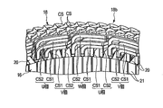
- FIG. 3 is a perspective view showing the first end face side of the stator
- FIG. 4 is a diagram schematically showing a part of a cross section of the stator and a divided segment.
- the stator 12 is driven by a three-phase (U-phase, V-phase and W-phase) AC power source.
- U-phase, V-phase and W-phase AC power source.
- a coil 18 corresponding to the U phase and connected in parallel a coil 18 corresponding to the V phase and connected in parallel
- a coil 18 corresponding to the W phase and connected in parallel are wound around the teeth 21 by a distributed arrangement. Has been done.
- the coil 18 includes three-phase (U, V, W) coils for each magnetic pole, and the coils for each phase are arranged in two of the six slots corresponding to one magnetic pole.
- the coils are not limited to those connected in parallel, and coils connected in series can also be used.
- Each coil 18 is composed of a segment coil formed by joining a plurality of coil segments formed of a flat conductor to each other.
- the flat conductor has a substantially rectangular shape in a cross section perpendicular to the longitudinal direction (cross section), or has at least two long sides facing each other in the shape of the cross section perpendicular to the longitudinal direction.
- cross section of the flat conductor is rectangular, the four corners do not have to be right angles and may be chamfered or rounded.
- the entire circumference of the flat conductor is covered with an insulating layer such as enamel, except for the conductive portion at the tip.
- each coil segment is located on the outside of the stator core 16 with the first linear portion and the second linear portion inserted and arranged in different slots 20 facing the second end surface 16b. It integrally has a bridge portion that connects the first linear portion and the second linear portion.
- the plurality of cross-linking portions constitute the coil end 18b.
- the first linear portion and the second linear portion each have an extending end portion extending outward from the first end surface 16a of the stator core 16. These extending ends are bent in the circumferential direction and form the coil end 18a of the coil 18.
- a plurality of, for example, four first linear portions or second linear portions are arranged in each slot 20, and the slots 20 are in a state where one sides of the rectangles face each other. They are arranged side by side in the radial direction of.
- the insulating sheet SP is wound around the four linear portions.
- the coil segment CS1 arranged on the innermost peripheral side of the slot 20 is composed of, for example, two divided segments DS1 and DS2.
- the divided segments DS1 and DS2 are formed of a flat conductor having a cross-sectional area of about half the cross-sectional area of the other coil segment CS, that is, a flat conductor thinner than the other coil segment CS.
- the divided segment DS1 is located on the outer side of the first linear portion LA1 and the second linear portion LA2 and the stator core 16 so as to face the second end surface 16b, and the first linear portion LA1.
- a cross-linking portion BA connecting the second linear portion LA2, and the cross-linking portion BA are integrally provided.
- the split segment DS2 is located on the outside of the stator core 16 with the first linear portion LB1 and the second linear portion LB2 facing the second end surface 16b, and the first linear portion LB1 and the second wire. It integrally has a cross-linked portion BB that connects the shaped portions LB2.
- the pair of first linear portions LA1 and LB1 are arranged in the slot 20 and are arranged in the first radial direction and adjacent to each other.
- the first linear portion LA1 is arranged adjacent to the innermost peripheral side of the slot 20, and the first linear portion LB1 is adjacent to the outer side in the radial direction of the first linear portion LA1.
- the second linear portions LA2 and LB2 are arranged in slots 20 separated from the first linear portions LA1 and LB1, for example, by five, and are adjacent to each other.
- the cross-linked portion BA and the cross-linked portion BB are arranged so as to intersect each other in the radial direction of the stator core 16.
- the arrangement relations of the second linear portions LA2 and LB2 are exchanged with those of the first linear portions LA1 and LB1, and the arrangement relations are reversed. That is, the second linear portions LA2 and LB2 are arranged side by side in the direction opposite to the first direction, the second linear portion LB2 is on the innermost peripheral side of the slot 20, and the second linear portion LA2 is the second line.
- the shape portion LB2 is arranged adjacent to the outside in the radial direction.
- the number of slots in which the second linear portions LA2 and LB2 are separated from the first linear portions LA1 and LB1 is not limited to five, and various values can be taken depending on the electrical design of the stator.
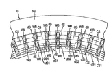
- FIG. 5 is an enlarged perspective view showing a part of the stator on the first end face side
- FIG. 6 is a plan view showing a part of the stator on the first end face side.
- the one-phase segment coil 18 sandwiches the first coil segment CS1 arranged on the innermost peripheral side of the slot 20 and the first coil segment CS1 from both sides in the circumferential direction.
- the first coil segment CS1 and the second coil segment CS2 are each double-rowed and are each composed of two divided segments.
- the U-phase first coil segment CS1 and the second coil segment CS2 are arranged side by side in two slots 20 adjacent to each other in the circumferential direction, and the V phase is placed in two slots 20 adjacent to these slots 20 in the circumferential direction.
- the first coil segment CS1 and the second coil segment CS2 of the above are arranged side by side.
- the first coil segment CS1 and the second coil segment CS2 of the W phase are placed.
- FIG. 7 is a perspective view showing an arrangement configuration of the first coil segment CS1 and the second coil segment CS2 of one phase.
- the first coil segment CS1 is composed of divided segments (first divided segment, second divided segment) DS1 and DS2.
- the divided segment DS1 is located on the outer side of the stator core 16 with the first linear portion LA1 and the second linear portion LA2 facing the second end surface 16b, and the first linear portion LA1 and the second linear portion LA2. It integrally has a cross-linking portion BA that connects the above.
- the split segment DS2 is located on the outside of the stator core 16 with the first linear portion LB1 and the second linear portion LB2 facing the second end surface 16b, and the first linear portion LB1 and the second wire. It integrally has a cross-linked portion BB that connects the shaped portions LB2.
- the pair of first linear portions LA1 and LB1 of the first coil segment CS1 are arranged in the slot 20 and are arranged in the radial direction and adjacent to each other.
- the first linear portion LA1 is arranged adjacent to the innermost peripheral side of the slot 20, and the first linear portion LB1 is adjacent to the outer side in the radial direction of the first linear portion LA1.
- the extending end portion protruding from the second end surface 16 of the stator core 16 is bent inward in the radial direction of the stator core 16 and further axially. It is folded.
- the extending ends of the first linear portions LA1 and LB1 are positioned radially inward from the inner peripheral end of the slot 20, that is, from the inner peripheral of the stator core 16. ..
- the cross-linked portion BA of the divided segment DS1 extends from the extending end of the first linear portion LA1 along the circumferential direction of the stator core 16 substantially in parallel with the second end surface 16b, and the first section SA1 and the first section SA1.
- the first crank portion CR1 that inclines outward in the radial direction from the end and extends substantially parallel to the second end surface 16b, and the circumferential direction from the end of the first crank portion CR1 to the extending end of the second linear portion LA2. It has a second section SA2 extending along the same direction and substantially parallel to the second end surface 16b.
- the first crank portion CR1 is located substantially in the middle between the first linear portion LA1 and the second linear portion LA2.
- the cross-linked portion BA is formed by bending a flat conductor in a thickness direction or a direction orthogonal to the thickness direction without twisting.
- the second linear portion LA2 is arranged in the slot 20 five away from the first linear portion LA1. Since the cross-linking portion BA of the split segment DS1 is a portion connecting the split segments DS1 housed in slots 20 having different positions in the circumferential direction of the stator core 16, the first section SA1 and the second section SA2 are connected. Is not necessarily parallel to (or substantially parallel to) the second end surface 16b of the stator core 16, and can have various shapes.
- the cross-linked portion BA of the divided segment DS1 faces the second end surface 16b at a distance.
- the first section SA1 is located so as to be offset from the inner peripheral edge of the stator core 16 to the inner peripheral side.
- the second section SA2 is positioned on the outer side in the radial direction by about three times the thickness of the divided segment DS1 with respect to the first section SA1.
- the second linear portion LA2 is arranged in the slot 20 in a state of being displaced outward in the radial direction by one thickness with respect to the first linear portion LA1.
- the bridge portion BB of the divided segment DS2 is the first section SB1 extending substantially parallel to the second end surface 16b along the circumferential direction of the stator core 16 from the extending end of the first linear portion LB1 and the first section SB1.
- the second crank portion CR2 that inclines outward in the radial direction from the end and extends substantially parallel to the second end surface 16b, and the circumferential direction from the end of the second crank portion CR2 to the extending end of the second linear portion LB2. It has a second section SB2 extending along the same direction and substantially parallel to the second end surface 16b.
- the second crank portion CR2 is located substantially in the middle between the first linear portion LB1 and the second linear portion LB2.
- the cross-linked portion BB is formed by bending a flat conductor in a thickness direction or a direction orthogonal to the thickness direction without twisting.
- the second linear portion LB2 is arranged in the slot 20 five away from the first linear portion LB1. Since the bridge portion BB of the split segment DS2 is also a portion connecting the split segment DS2 housed in the slots 20 having different positions in the circumferential direction of the stator core 16, the first section SB1 and the second section
- the SB2 does not necessarily have to be parallel (or substantially parallel) to the second end surface 16b of the stator core 16, and may have various shapes.
- the first linear portion LB1 and the second linear portion LB2 are higher than the first linear portion LA1 and the second linear portion LA2 of the divided segment DS1 by almost twice the width of the flat conductor from the stator core 16. It extends in the axial direction.
- the cross-linked portion BB faces the second end surface 16b substantially in parallel with a larger interval than the cross-linked portion BA.
- the first section SB1 is located so as to be offset from the inner peripheral side end of the slot 20 to the inner peripheral side, and is substantially located on the inner peripheral edge of the stator core 16.
- first section SB1 is positioned so as to be offset outward in the radial direction by the thickness of the flat conductor with respect to the first section SA1 of the divided segment DS1, and is located above the axial direction by the width of the flat conductor (the first). 2 It is positioned so as to be offset from the end surface 16b).
- the second crank portion CR2 is located above the first crank portion CR1 in the axial direction, and extends so as to intersect the first crank portion CR1.
- the extension length (diametric height) (second length) of the second crank portion CR2 along the longitudinal direction of the flat conductor is the extension length (first length) of the first crank portion CR1. It is formed in less than half.
- the second section SB2 is positioned inward in the radial direction by the thickness of the flat conductor with respect to the second section SA2 of the divided segment DS1, and further upward by the width of the flat conductor (in the axial direction). It is positioned so as to be offset from the second end surface 16b).
- the second linear portion LB2 is located on the inner side in the radial direction with respect to the first linear portion LB1 and is arranged on the innermost peripheral side in the slot 20. In this way, the cross-linking portion BA of the split segment DS1 and the cross-linking portion BB of the split segment DS2 intersect and extend in the radial direction, and the positional relationship between the first linear portions LA1 and LB1 is in the second linear shape.
- the positional relationship between the parts LA2 and LB2 is reversed. That is, the first linear portion LA1 is located inside the first linear portion LB1 in the radial direction, and the second linear portion LA2 is located outside the radial portion with respect to the second linear portion LB2. There is.
- the second coil segment CS2 arranged so as to sandwich the first coil segment CS1 from both sides in the circumferential direction is composed of divided segments (third divided segment, fourth divided segment) DS3 and DS4.
- the split segment DS3 is located on the outer side of the stator core 16 with the first linear portion LC1 and the second linear portion LC2 facing the second end surface 16b, and the first linear portion LC1 and the second linear portion LC2. It has a bridged portion BC and a bridge portion BC which are connected to each other.
- the split segment DS4 is located on the outside of the stator core 16 with the first linear portion LD1 and the second linear portion LD2 facing the second end surface 16b, and the first linear portion LD1 and the second line. It integrally has a cross-linked portion BD that connects the shaped portions LD2.
- the pair of first linear portions LC1 and LD1 of the second coil segment CS2 is a slot adjacent to (outside the circumferential direction) of the slot 20 in which the first linear portions LA1 and LB1 of the first coil segment CS1 are arranged. They are arranged within 20 and are adjacent to each other side by side in the first radial direction.
- the first linear portion LC1 is arranged adjacent to the innermost peripheral side of the slot 20, and the first linear portion LD1 is adjacent to the outer side in the radial direction of the first linear portion LC1.
- the extending end portion protruding from the second end surface 16 of the stator core 16 is bent inward in the radial direction of the stator core 16 and further bent in the axial direction. ing.
- the extending ends of the first linear portions LC1 and LD1 are displaced inward in the radial direction from the inner peripheral end of the slot 20, that is, from the inner peripheral of the stator core 16. Is located.
- the bridged portion BC of the divided segment DS3 is a first section SC1 extending substantially parallel to the second end surface 16b along the circumferential direction of the stator core 16 from the extending end of the first linear portion LC1 and the first section SC1.
- a first crank portion (third crank portion) CR3 that inclines outward in the radial direction from the end and extends substantially parallel to the second end surface 16b, and an extension of the second linear portion LA2 from the end of the first crank portion CR3. It has a second section SC2 extending along the circumferential direction to the protruding end portion and substantially parallel to the second end surface 16b.
- the first crank portion CR3 is located substantially in the middle between the first linear portion LC1 and the second linear portion LC2.
- the cross-linked portion BC is formed by bending a flat conductor in a thickness direction or a direction orthogonal to the thickness direction without twisting.
- the second linear portion LC2 is a slot 20 seven away from the first linear portion LC1, that is, one of the slots 20 in which the second linear portions LA2 and LB2 of the first coil segment CS1 are arranged. It is arranged in the next slot 20 (outside in the circumferential direction).
- the number of slots in which the second linear portion LC2 is separated from the first linear portion LC1 is not limited to seven, and various values can be taken depending on the electrical design of the stator.
- the first linear portion LC1 and the second linear portion LC2 are higher than the first linear portion LA1 and the second linear portion LA2 of the divided segment DS1 by approximately the width of the rectangular conductor and are axially higher than the stator core 16. It is extended. As a result, the cross-linked portion BC faces the second end surface 16b substantially in parallel with a larger interval than the cross-linked portion BA. Since the bridge portion BC of the split segment DS3 is also a portion connecting the split segment DS3 housed in the slots 20 having different positions in the circumferential direction of the stator core 16, the first section SC1 and the second section The SC2 does not necessarily have to be parallel (or substantially parallel) to the second end surface 16b of the stator core 16, and may have various shapes.
- the first section SC1 of the bridge portion BC is located so as to be offset from the inner peripheral edge of the stator core 16 to the inner peripheral side.
- the second section SC2 is positioned with respect to the first section SC1 so as to be displaced outward in the radial direction by about three times the thickness of the divided segment DS3.
- the second linear portion LC2 is arranged in the slot 20 in a state of being displaced outward in the radial direction by one thickness with respect to the first linear portion LC1.
- the first section SC1, the first crank section CR3, and the second section SC2 of the bridge section BC are vertically overlapped with the first section SA1, the first crank section CR1, and the second section SA2 of the divided segment DS1, respectively. There is.
- the bridged portion BD of the divided segment DS4 has a first section SD1 extending substantially parallel to the second end surface 16b along the circumferential direction of the stator core 16 from the extending end of the first linear portion LD1 and the first section SD1.
- a second crank portion (fourth crank portion) CR4 that inclines outward in the radial direction from the end and extends substantially parallel to the second end surface 16b, and an extension of the second linear portion LD2 from the end of the second crank portion CR4. It has a second section SD2 extending along the circumferential direction to the protruding end portion and substantially parallel to the second end surface 16b.
- the second crank portion CR4 is located substantially in the middle between the first linear portion LD1 and the second linear portion LD2.
- the cross-linked portion BD is formed by bending a flat conductor in a thickness direction or a direction orthogonal to the thickness direction without twisting.
- the second linear portion LD2 is arranged in the slot 20 seven apart from the first linear portion LD1.
- the number of slots in which the second linear portion LD2 is separated from the first linear portion LD1 is not limited to seven, and various values can be taken depending on the electrical design of the stator.
- the bridge portion BD of the split segment DS4 is also a portion connecting the split segment DS4 housed in the slots 20 having different positions in the circumferential direction of the stator core 16, the first section SD1 and the second section The SD2 does not necessarily have to be parallel (or substantially parallel) to the second end surface 16b of the stator core 16, and may have various shapes.
- the first linear portion LD1 and the second linear portion LD2 are higher than the first linear portion LC1 and the second linear portion LC2 of the divided segment DS3 by almost twice the width of the rectangular conductor from the stator core 16. It extends in the axial direction.
- the cross-linked portion BD faces the second end surface 16b substantially in parallel with a larger interval than the cross-linked portion BC.
- the first section SD1 is located so as to be offset from the inner peripheral side end of the slot 20 to the inner peripheral side, and is substantially located on the inner peripheral edge of the stator core 16.
- first section SD1 is displaced outward in the radial direction by the thickness of the flat conductor with respect to the first section SC1 of the divided segment DS3, and is axially offset by twice the width of the flat conductor. It is located offset upward (in the direction away from the second end surface 16b).
- the second crank portion CR4 is located above the first crank portion CR3 in the axial direction, and extends so as to intersect the first crank portion CR3.
- the extension length (diameter height) of the second crank portion CR4 along the longitudinal direction of the flat conductor is formed to be half or less of the extension length of the first crank portion CR3.
- the second section SD2 is displaced inward in the radial direction by the thickness of the flat conductor with respect to the second section SC2 of the divided segment DS3, and further, in the axial direction by twice the width of the flat conductor. (Direction away from the second end surface 16b).
- the second linear portion LD2 is located on the inner side in the radial direction with respect to the first linear portion LC1 and is arranged on the innermost peripheral side in the slot 20.
- the first section SD1, the second crank portion CR4, and the second section SD2 of the bridge portion BD are arranged so as to overlap with each other in the axial direction on the first section SB1, the second crank portion CR2, and the second section SB2 of the divided segment DS2, respectively. There is.
- the cross-linking portion BC of the split segment DS3 and the cross-linking portion BD of the split segment DS4 intersect and extend in the radial direction, and the positional relationship between the first linear portions LC1 and LD1 is in the second linear shape.
- the positional relationship between the parts LD2 and LD2 is reversed. That is, the first linear portion LC1 is located inside the first linear portion LD1 in the radial direction, and the second linear portion LC2 is located outside the radial portion with respect to the second linear portion LD2.
- the second linear portions LC2 and LD2 are arranged side by side in the direction opposite to the first direction described above.
- FIG. 8 is a perspective view showing a part of the stator on the first end face side
- FIG. 9 is a plan view showing a part of the stator on the first end face side.
- the first linear portion and the second linear portion of the coil segment CS extend from the first end surface 16a to the outside of the stator core 16. It has an extension.
- Each of these extending portions is bent at a predetermined angle in the circumferential direction and extends at an angle with respect to the axial direction.
- the first linear portion and the second linear portion of the divided segments DS1 to DS4 each have an extending portion extending from the first end surface 16a to the outside of the stator core 16.
- Each of these extending portions is bent at a predetermined angle in the circumferential direction and extends at an angle with respect to the axial direction.
- the extending end of each extending end portion constitutes an end surface (joint surface) ds substantially parallel to the first end surface 16a.
- the extending portions of the four first or second linear portions inserted into each slot 20 are alternately bent in one direction and the opposite direction. That is, the extending portion of the first or second linear portion of the coil segment CS located on the outermost circumference is bent in one direction in the circumferential direction of the stator core 16, and the first or second coil segment CS on the inner side is bent. The extending portion of the second linear portion is bent in the other direction (reverse direction) in the circumferential direction. Further, the linear portion of the first or second linear portion of the coil segment CS on the inner side is bent in the one direction. Further, the extending portion of the first or second linear portion of the divided segments CS1 and CS2 located on the innermost circumference is bent in the other direction.
- each of the extension portions of the coil segments CS1 and CS2 on the innermost circumference includes two end faces ds1 and ds2 of the two divided segments.
- the end faces ds of the four extension portions in each row are welded to each other by two (two each) and are electrically conductive. That is, the end faces ds of the two extending portions on the outer peripheral side are welded to each other to form a weld bead WB straddling the two end face ds.
- the end faces ds of the two extending portions on the inner peripheral side are welded to each other to form a weld bead WB.
- the two end faces ds1 (or ds2) of the two split segments are joined to each other by welding, the split segments are electrically joined to each other, and the two end faces ds1 (or ds2) are adjacent to the coil segment CS.
- a weld bead WB straddling the three end faces ds, ds1, ds1 (or the three end faces ds, ds2, ds2) is formed.
- laser welding can be used for welding the end face ds of the extension portion.
- Each weld or joint of the coil segment is covered with an insulating material such as powder coating or varnish.
- a U-phase connection terminal TU, a V-phase connection terminal TV, and a W-phase connection terminal TW, which are not shown, are connected to three of the coils 18.
- This embodiment exemplifies a case where the number of parallel coils of the stator 12 is 2, and connection ends 8 are provided according to the number of parallel coils.
- a three-phase, 12-pole, 72-slot rotary electric machine is configured, the number of slots of the stator core 16 corresponding to one pole is 6 slots, and the coil of each phase is 1.
- the magnetic poles are arranged in two slots.
- the coil 18 by forming the coil 18 with a segment coil, the coil ends 18a and 18b protruding from the first end surface 16a and the second end surface 16b of the stator core 16 are projected.
- the height can be significantly reduced and the stator 12 can be downsized.
- the coil segments CS1 and CS2 located at least on the innermost circumference are double-rowed, and a plurality of divided segments DS1 made of a flat conductor having a thin wire diameter. It is composed of ⁇ DS4.
- the segment coils By arranging the segment coils on the innermost circumference in multiple rows, it is possible to suppress a decrease in the slot space utilization rate due to an increase in the number of conductors and maintain the effect of reducing loss at low speed rotation.
- the cross-sectional area of the conductor orthogonal to the magnetic flux traversing the slot 20 in the circumferential direction is reduced, and the eddy current generated in the conductor during high-speed rotation and the loss caused by the eddy current are reduced. can do.
- the double-rowed coil segment since both ends of the plurality of divided segments are welded to each other and electrically joined to each other, a closed circuit exists between the welding points in the double-rowed set of coils.
- FIG. 10 is a diagram schematically showing a passing state of magnetic flux in a double-rowed coil segment.
- FIG. 10A when the cross-linked portions of the two divided segments DS1 and DS2 are cross-linked and the welding points at both ends are dislocated, the loops between the welding points and the cross-linking positions are oriented in opposite directions. Magnetic flux will pass through. Therefore, as shown in FIG. 10B, the directions of the circulating currents I1 and I2 generated in one loop and the other loop are opposite to each other, and they act to cancel each other out. Therefore, the generation of circulating current is suppressed, and it becomes possible to prevent an increase in loss.
- the dislocation configuration that reverses the positional relationship between both ends is such that the split segments DS1 and DS2 are bent in the thickness direction or in the direction orthogonal to the thickness direction to form the first section SA1, SB1 and the second section SA2, SB2. It is obtained by changing the lane. Therefore, the segment coil can be easily manufactured and assembled as compared with the case of twisting.
- the first crank portion CR1 and CR3 and the second crank portion CR2 and CR4 of the cross-linking portion are in the circumferential direction. It is located directly above the slot located between the coil segments of the other phase adjacent to the coil segment of the other phase, and can be arranged in the vicinity of the coil segment of the other phase without interfering with the coil segment of the other phase. Therefore, it is possible to reduce the size and simplification of the coil end 18b.
- the first crank portions CR1 and CR3 having a long wire length are arranged below the second crank portions CR2 and CR3 having a short wire length, that is, on the stator core 16 side. Installation and assembly work of the coil segment can be facilitated. From the above, according to the present embodiment, it is possible to obtain a stator of a rotary electric machine capable of reducing the size and simplification of the coil end while suppressing the generation of eddy current.
- FIG. 11 is a perspective view showing an arrangement configuration of the first coil segment CS1 and the second coil segment CS2 of one phase of the stator according to the second embodiment
- FIG. 12 is a part of the stator on the first end surface side. It is a plan view which shows.
- the cross-linking portions BB and BD having the short crank portions CR2 and CR4 are stators.
- the iron cores 16 are arranged so as to overlap with each other in the axial direction, and the cross-linked portions BA and BC having the long crank portions CR1 and CR2 are arranged on these cross-linked portions.
- the cross-linked portions BA and BC are arranged so as to overlap each other in the radial direction of the stator core 16.
- the first coil segment CS1 is composed of the divided segments DS1 and DS2.
- the pair of first linear portions LA1 and LB1 of the first coil segment CS1 are arranged in the slot 20 and are arranged in the radial direction and adjacent to each other.
- the first linear portion LA1 is arranged adjacent to the innermost peripheral side of the slot 20, and the first linear portion LB1 is adjacent to the outer side in the radial direction of the first linear portion LA1.
- the extending end portion protruding from the second end surface 16 of the stator core 16 is bent inward in the radial direction of the stator core 16 and further axially. It is folded.
- the extending ends of the first linear portions LA1 and LB1 are positioned radially inward from the inner peripheral end of the slot 20, that is, from the inner peripheral of the stator core 16. ..
- the cross-linked portion BA of the divided segment DS1 extends from the extending end of the first linear portion LA1 along the circumferential direction of the stator core 16 substantially in parallel with the second end surface 16b, and the first section SA1 and the first section SA1.
- the first crank portion CR1 that inclines outward in the radial direction from the end and extends substantially parallel to the second end surface 16b, and the circumferential direction from the end of the first crank portion CR1 to the extending end of the second linear portion LA2. It has a second section SA2 extending along the same direction and substantially parallel to the second end surface 16b.
- the first crank portion CR1 is located substantially in the middle between the first linear portion LA1 and the second linear portion LA2.
- the cross-linked portion BA is formed by bending a flat conductor in a thickness direction or a direction orthogonal to the thickness direction without twisting.
- the second linear portion LA2 is arranged in the slot 20 five away from the first linear portion LA1.
- the cross-linked portion BA of the divided segment DS1 faces the second end surface 16b at a distance.
- the first section SA1 is located so as to be offset from the inner peripheral edge of the stator core 16 to the inner peripheral side.
- the second section SA2 is positioned on the outer side in the radial direction by about three times the thickness of the divided segment DS1 with respect to the first section SA1.
- the second linear portion LA2 is arranged in the slot 20 in a state of being displaced outward in the radial direction by one thickness with respect to the first linear portion LA1.
- the bridge portion BB of the divided segment DS2 is the first section SB1 extending substantially parallel to the second end surface 16b along the circumferential direction of the stator core 16 from the extending end of the first linear portion LB1 and the first section SB1.
- the second crank portion CR2 that inclines outward in the radial direction from the end and extends substantially parallel to the second end surface 16b, and the circumferential direction from the end of the second crank portion CR2 to the extending end of the second linear portion LB2. It has a second section SB2 extending along the same direction and substantially parallel to the second end surface 16b.
- the second crank portion CR2 is located substantially in the middle between the first linear portion LB1 and the second linear portion LB2.
- the cross-linked portion BB is formed by bending a flat conductor in a thickness direction or a direction orthogonal to the thickness direction without twisting.
- the second linear portion LB2 is arranged in the slot 20 five away from the first linear portion LB1.
- the first linear portion LB1 and the second linear portion LB2 are lower than the first linear portion LA1 and the second linear portion LA2 of the divided segment DS1 by almost twice the width of the flat conductor from the stator core 16. It extends in the axial direction.
- the cross-linked portion BB faces the second end surface 16b substantially in parallel with a space smaller than that of the cross-linked portion BA.
- the first section SB1 is located so as to be offset from the inner peripheral side end of the slot 20 to the inner peripheral side, and is substantially located on the inner peripheral edge of the stator core 16.
- first section SB1 is positioned so as to be offset outward in the radial direction by the thickness of the flat conductor with respect to the first section SA1 of the divided segment DS1, and is located downward in the axial direction by the width of the flat conductor (the first). 2 It is positioned so as to be offset in the direction approaching the end surface 16b).
- the second crank portion CR2 is positioned so as to overlap below the first crank portion CR1 in the axial direction, and extends so as to intersect the first crank portion CR1.
- the extension length (height in the radial direction) of the second crank portion CR2 along the longitudinal direction of the flat conductor is formed to be half or less of the extension length of the first crank portion CR1.
- the second section SB2 is positioned inward in the radial direction by the thickness of the flat conductor with respect to the second section SA2 of the divided segment DS1, and further downward by the width of the flat conductor (in the axial direction). It is positioned so as to be offset in the direction approaching the second end surface 16b).
- the second linear portion LB2 is located on the inner side in the radial direction with respect to the second linear portion LB1 and is arranged on the innermost peripheral side in the slot 20.
- the cross-linking portion BA of the split segment DS1 and the cross-linking portion BB of the split segment DS2 intersect and extend in the radial direction, and the positional relationship between the first linear portions LA1 and LB1 is in the second linear shape.
- the positional relationship between the parts LA2 and LB2 is reversed. That is, the first linear portion LA1 is located inside the first linear portion LB1 in the radial direction, and the second linear portion LA2 is located outside the radial portion with respect to the second linear portion LB2. There is.
- the second coil segment CS2 arranged so as to sandwich the first coil segment CS1 from both sides in the circumferential direction is composed of the divided segments DS3 and DS4.
- the pair of first linear portions LC1 and LD1 of the second coil segment CS2 is a slot adjacent to (outside the circumferential direction) of the slot 20 in which the first linear portions LA1 and LB1 of the first coil segment CS1 are arranged. They are arranged within 20 and are adjacent to each other in a radial direction.
- the first linear portion LC1 is arranged adjacent to the innermost peripheral side of the slot 20, and the first linear portion LD1 is adjacent to the outer side in the radial direction of the first linear portion LC1.
- the extending end portion protruding from the second end surface 16 of the stator core 16 is bent inward in the radial direction of the stator core 16 and further bent in the axial direction. ing.
- the extending ends of the first linear portions LC1 and LD1 are positioned radially inward from the inner peripheral end of the slot 20, that is, from the inner peripheral of the stator core 16. ..
- the extending end portion of the first linear portion LC1 is larger than the first linear portion LD1, and is located, for example, about three times the thickness of the first linear portion, offset inward in the radial direction. ..
- the bridged portion BC of the divided segment DS3 has a first section SC1 extending substantially parallel to the second end surface 16b along the circumferential direction of the stator core 16 from the extending end of the first linear portion LC1 and the first section SC1. Circumferential direction from the end of the first crank portion CR3 and the extending end of the second linear portion LA2, which is inclined outward from the end in the radial direction and extends substantially parallel to the second end surface 16b.
- the second section SC2 extending substantially parallel to the second end surface 16b, and provided in the middle of the second section SC2, inclined outward in the radial direction and extending substantially parallel to the second end surface 16b. It has a fifth crank portion CR5.
- the first crank portion CR3 is located substantially in the middle between the first linear portion LC1 and the second linear portion LC2.
- the extended length (height in the radial direction) of the first crank portion CR3 is formed to be about three times the thickness of the flat conductor.
- the radial extension length of the fifth crank portion CR5 is formed to be substantially equal to the thickness of the flat conductor.
- the cross-linked portion BC is formed by bending a flat conductor in a thickness direction or a direction orthogonal to the thickness direction without twisting.
- the second linear portion LC2 is adjacent to the slot 20 seven away from the first linear portion LC1, that is, the slot 20 in which the second linear portions LA2 and LB2 of the first coil segment CS1 are arranged ( It is arranged in the slot 20 (outside in the circumferential direction).
- the first linear portion LC1 and the second linear portion LC2 extend axially from the stator core 16 by a height substantially equal to that of the first linear portion LA1 and the second linear portion LA2 of the divided segment DS1.
- the cross-linked portion BC faces substantially parallel to the second end surface 16b at an interval equivalent to that of the cross-linked portion BA, and is further located radially inside the cross-linked portion BA and faces the cross-linked portion BA in the radial direction. ing.
- the first section SC1 of the cross-linked portion BC is located so as to be offset from the inner peripheral edge of the stator core 16 to the inner peripheral side.
- the second section SC2 is positioned with respect to the first section SC1 so as to be displaced outward in the radial direction by about three times the thickness of the divided segment DS3.
- the terminal portion of the second section SC2 is positioned so as to be further displaced outward in the radial direction by one thickness.
- the second linear portion LC2 is arranged in the slot 20 in a state of being displaced outward in the radial direction by one thickness with respect to the first linear portion LC1.
- the first section SC1, the first crank section CR3, and the second section SC2 of the bridge section BC are radially overlapped with the first section SA1, the first crank section CR1, and the second section SA2 of the divided segment DS1, respectively. There is.
- the bridged portion BD of the divided segment DS4 has a first section SD1 extending substantially parallel to the second end surface 16b along the circumferential direction of the stator core 16 from the extending end of the first linear portion LD1 and the first section SD1.
- the second crank portion CR4 that inclines outward in the radial direction from the end and extends substantially parallel to the second end surface 16b, and the circumferential direction from the end of the second crank portion CR4 to the extending end of the second linear portion LD2. It has a second section SD2 extending along the line and substantially parallel to the second end surface 16b.
- the second crank portion CR4 is located substantially in the middle between the first linear portion LD1 and the second linear portion LD2.
- the cross-linked portion BD is formed by bending a flat conductor in a thickness direction or a direction orthogonal to the thickness direction without twisting.
- the second linear portion LD2 is arranged in the slot 20 seven apart from the first linear portion LD1.
- the first linear portion LD1 and the second linear portion LD2 extend axially from the stator core 16 lower than the first linear portion LC1 and the second linear portion LC2 of the split segment DS3 by the width of the flat conductor. It is out.
- the cross-linked portion BD faces the second end surface 16b substantially in parallel with a space smaller than that of the cross-linked portion BC.
- the first section SD1 is located so as to be offset from the inner peripheral side end of the slot 20 to the inner peripheral side, and is substantially located on the inner peripheral edge of the stator core 16.
- first section SD1 is located so as to be displaced outward in the radial direction by three times the thickness of the flat conductor with respect to the first section SC1 of the divided segment DS3, and is axially displaced by the width of the flat conductor. It is located offset downward (in the direction approaching the second end surface 16b).
- the second crank portion CR4 is positioned so as to overlap below the first crank portion CR3 in the axial direction, and extends so as to intersect the first crank portion CR3.
- the extension length (height in the radial direction) of the second crank portion CR4 along the longitudinal direction of the flat conductor is formed to be about 1/3 of the extension length of the first crank portion CR3.
- the second section SD2 is located at the same radial position as the second section SC2 of the split segment DS3, and is further downward in the axial direction by the width of the flat conductor (direction approaching the second end surface 16b). It is located offset to. That is, the second section SD2 is located between the second section SB2 of the divided segment DS2 and the second section SC2 of the divided segment DS3, and is arranged so as to overlap in the axial direction. As a result, the second linear portion LD2 is located on the inner side in the radial direction with respect to the second linear portion LC1, and is arranged on the innermost peripheral side in the slot 20.
- the first section SD1, the second crank portion CR4, and the second section SD2 of the bridge portion BD are arranged so as to overlap with each other in the axial direction on the first section SB1, the second crank portion CR2, and the second section SB2 of the divided segment DS2, respectively. There is.
- the cross-linking portion BC of the split segment DS3 and the cross-linking portion BD of the split segment DS4 intersect and extend in the radial direction, and the positional relationship between the first linear portions LC1 and LD1 is in the second linear shape.
- the positional relationship between the parts LD2 and LD2 is reversed. That is, the first linear portion LC1 is located inside the first linear portion LD1 in the radial direction, and the second linear portion LC2 is located outside the radial portion with respect to the second linear portion LD2.
- the other configurations of the stator are the same as those in the first embodiment described above.
- the first section and the second section of the crosslinked portion of the divided segment do not necessarily have to be parallel (or substantially parallel) to the second end surface 16b of the stator core 16 and have various shapes. Can be.
- the dislocation configuration that reverses the positional relationship between both ends of the first coil segment CS1 and the second coil segment CS2 twists the divided segments DS1, DS2, DS3, and DS4. It is obtained by bending the first section SA1, SB1, SC1, SD1 and the second section SA2, SB2, SC2, SD2 by bending in the thickness direction or the direction orthogonal to the thickness direction. Therefore, the segment coil can be easily manufactured and assembled as compared with the case of twisting.
- the first crank portion CR1 and CR3 and the second crank portion CR2 and CR4 of the cross-linking portion are in the circumferential direction. It is located directly above the slot located between the coil segments of the other phase adjacent to the coil segment of the other phase, and can be arranged in the vicinity of the coil segment of the other phase without interfering with the coil segment of the other phase. Therefore, it is possible to reduce the size and simplification of the coil end 18b.
- the cross-linked portions BB and BD having the short crank portions CR2 and CR4 are in the axial direction of the stator core 16.
- cross-linking portions BA and BC having long crank portions CR1 and CR2 are arranged.
- the cross-linked portions BA and BC are arranged so as to overlap each other in the radial direction of the stator core 16. As a result, the extended height of the coil end can be reduced, and further miniaturization can be achieved. From the above, according to the second embodiment, it is possible to obtain a stator of a rotary electric machine capable of reducing the size and simplification of the coil end while suppressing the generation of eddy current.
- FIG. 13 is a perspective view showing an arrangement configuration of the first coil segment CS1 and the second coil segment CS2 of one phase of the stator according to the third embodiment
- FIG. 14 is a part of the stator on the first end surface side. It is a plan view which shows.
- the cross-linking portion BC of the split segment DS3 of the second coil segment CS2 is arranged so as to overlap the cross-linking portion BA of the split segment DS1 of the first coil segment CS1 in the radial direction of the stator core 16. Has been done.
- the cross-linking portion BC of the split segment DS3 is arranged so as to overlap the cross-linking portion BA of the split segment DS1 in the radial direction of the stator core 16.
- the first linear portion LC1 of the divided segment DS3 is arranged on the innermost peripheral side of the slot 20.
- the extending end portion protruding from the second end surface 16 of the stator core 16 is bent inward in the radial direction of the stator core 16 and further bent in the axial direction. ..
- the extending end portion of the first linear portion LC1 is positioned radially inward from the inner peripheral side end of the slot 20 by, for example, the thickness of the first linear portion.
- the bridged portion BC of the divided segment DS3 is a first section SC1 extending substantially parallel to the second end surface 16b along the circumferential direction of the stator core 16 from the extending end of the first linear portion LC1 and the first section SC1.
- It has a second section SC2 extending along the same direction and substantially parallel to the second end surface 16b.
- the first crank portion CR3 is located substantially in the middle between the first linear portion LC1 and the second linear portion LC2.
- the extended length (height in the radial direction) of the first crank portion CR3 is formed to be about three times the thickness of the flat conductor.
- the cross-linked portion BC is formed by bending a flat conductor in a thickness direction or a direction orthogonal to the thickness direction without twisting.
- the second linear portion LC2 is adjacent to the slot 20 seven away from the first linear portion LC1, that is, the slot 20 in which the second linear portions LA2 and LB2 of the first coil segment CS1 are arranged ( It is arranged in the slot 20 (outside in the circumferential direction).
- the first linear portion LC1 is higher than the first linear portion LA1 of the divided segment DS1 by the width of the flat conductor and extends axially from the stator core 16.
- the first section SC1, the first crank section CR3, and the second section SC2 of the bridge section BC are axial to the first section SA1, the first crank section CR1, and the second section SA2 of the bridge section BA of the split segment DS1, respectively. They are arranged so that they overlap in the direction.
- the other configurations of the first coil segment CS1 and the second coil segment CS2 are the same as those of the second embodiment described above.
- the first section and the second section of the crosslinked portion of the divided segment do not necessarily have to be parallel (or substantially parallel) to the second end surface 16b of the stator core 16, and may have various shapes. be able to.
- the dislocation configuration that reverses the positional relationship between both ends of the first coil segment CS1 and the second coil segment SC2 twists the divided segments DS1, DS2, DS3, and DS4.
- the segment coil can be easily manufactured and assembled as compared with the case of twisting.
- the first crank portion CR1 and CR3 and the second crank portion CR2 and CR4 of the cross-linking portion are in the circumferential direction. It is located directly above the slot located between the coil segments of the other phase adjacent to the coil segment of the other phase, and can be arranged in the vicinity of the coil segment of the other phase without interfering with the coil segment of the other phase.
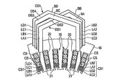
- FIG. 15 schematically shows a part of the cross section of the stator and the divided segment according to the first modification.
- the coil segment CS1 arranged on the innermost peripheral side of the slot 20 is divided into three divided segments (first, second, and third divided segments) DS1, DS2, and DS3. It is divided and multi-columned.
- the divided segments DS1, DS2, and DS3 are formed by a flat conductor having a cross-sectional area of about 1/3 of the cross-sectional area of the other coil segment CS, that is, by a flat conductor thinner than the other coil segment CS. Has been done.
- the divided segment DS1 is located on the outer side of the stator core 16 with the first linear portion LA1 and the second linear portion LA2 facing the second end surface 16b, and the first linear portion LA1 and the second linear portion LA2. It integrally has a cross-linking portion BA that connects the above.
- the divided segment DS2 is located on the outside of the stator core 16 with the first linear portion LB1 and the second linear portion LB2 facing the second end surface 16b, and the first linear portion LB1 and the second linear portion LB2. It integrally has a cross-linking portion BB that connects the above.
- the split segment DS3 is located on the outside of the stator core 16 with the first linear portion LC1 and the second linear portion LC2 facing the second end surface 16b, and the first linear portion LC1 and the second wire. It integrally has a cross-linked portion BC that connects the shaped portions LC2.
- the three first linear portions LA1, LB1, and LC1 are arranged in the slot 20 and are arranged in the radial direction and adjacent to each other.
- the first linear portion LA1 is on the innermost peripheral side of the slot 20
- the first linear portion LB1 is on the radial outside of the first linear portion LA1
- the first linear portion LC1 is on the first linear portion. It is arranged adjacent to the outside of the radial direction of the LB1.
- the second linear portions LA2, LB2, and LC2 are arranged in slots 20 five apart from the first linear portions LA1, LB1, and LC1 and are adjacent to each other.
- the cross-linking portion BA is arranged so as to intersect the cross-linking portion BB in the radial direction of the stator core 16, and a part of the cross-linking portion BA is located outside the cross-linking portion BB in the radial direction.
- the cross-linking portion BC is arranged so as to intersect the cross-linking portion BB in the radial direction of the stator core 16, and a part of the cross-linking portion BC is located inside the cross-linking portion BB in the radial direction.
- the second linear portion LC2 is arranged adjacent to the innermost peripheral side of the slot 20, and the second linear portion LA2 is adjacent to the outer side in the radial direction of the second linear portion LC2 with the second linear portion LB2 interposed therebetween.
- Any of the configurations shown in the first, second, and third embodiments described above can be applied to the configurations of the cross-linked portions BA, BB, and BC.
- the cross-sectional area of the conductor orthogonal to the magnetic flux traversing the slot 20 in the circumferential direction is further reduced, and the eddy current generated in the conductor during high-speed rotation and the cause thereof. Loss can be reduced.
- the generation of circulating current can be suppressed by cross-linking the crosslinked portions of the three divided segments to dislocate the positional relationship between the first linear portion and the positional relationship of the second linear portion. Therefore, it is possible to reduce the loss by using the innermost coil which is double-rowed without causing a new loss increase factor.
- FIG. 16 schematically shows a part of the cross section of the stator and the divided segment according to the second modification.
- the coil segment CS1 arranged on the innermost peripheral side of the slot 20 has four divided segments (first, second, third, fourth divided segments) DS1 and D2. , D3, and D4 are divided into multiple rows.
- the divided segments DS1, DS2, and DS3 are formed of flat conductors having a cross-sectional area of about 1/4 of the cross-sectional area of the other coil segments CS.
- the divided segment DS4 is located on the outer side of the first linear portion LD1 and the second linear portion LD2 and the stator core 16 so as to face the second end surface 16b. It integrally has a cross-linked portion BD that connects the linear portion LD1 and the second linear portion LD2.
- the four first linear portions LA1, LB1, LC1, and LD1 are arranged in the slot 20 and are arranged radially and adjacent to each other.
- the first linear portion LA1 is located on the innermost peripheral side of the slot 20, and the first linear portions LB1, LC1, and LD1 are arranged in this order on the outer side thereof.
- the second linear portions LA2, LB2, LC2, and LD2 are arranged in slots 20 five apart from the first linear portions LA1, LB1, and LC1 and are adjacent to each other.
- the cross-linking portions BA and BB of the split segments DS1 and DS2 are arranged so as to intersect the split snow surface and the cross-linking portions BC and BD of the DS3 and DS4 in the radial direction of the stator core 16 and are one of the cross-linking portions BA and BB.
- the portion is located on the radial outer side of the cross-linked portions BC and BD.
- the second linear portions LA2, LB2 and the second linear portions LC2, LD2 are interchanged with the first linear portions LA1, LB1 and the first linear portions LC1, LD1 and have the opposite arrangement relation. It has become.
- the second linear portion LC2 is located on the innermost peripheral side of the slot 20, and the second linear portions LD2, LA2, and LB2 are arranged in this order on the outer side thereof.
- Any of the configurations shown in the first, second, and third embodiments described above can be applied to the configurations of the cross-linked portions BA, BB, BC, and BD.
- the cross-sectional area of the conductor orthogonal to the magnetic flux crossing the slot 20 in the circumferential direction is further reduced, and it is generated in the conductor at high speed rotation.
- the eddy current and the loss caused by this can be reduced.
- the generation of circulating current can be suppressed by cross-linking the crosslinked portions of the four divided segments to dislocate the positional relationship between the first linear portion and the positional relationship of the second linear portion. Therefore, it is possible to reduce the loss by using the innermost coil which is double-rowed without causing a new loss increase factor.
- FIG. 17 schematically shows a part of the cross section of the stator and the divided segment according to the third modification.
- the third modification in addition to the coil segment CS1 arranged on the innermost peripheral side of the slot 20, a plurality of coil segments CS4 arranged on the outermost peripheral side of the slot 20, for example, two.
- the division segments DS1 and DS2 are divided into multiple rows.
- the divided segments DS1 and DS2 are formed of flat conductors having a cross-sectional area of about 1 ⁇ 2 of the cross-sectional area of the other coil segments CS.
- the divided segment DS1 of the coil segment CS4 is located on the outer side of the first linear portion LA1 and the second linear portion LA2 and the stator core 16 so as to face the second end surface 16b, and the first linear portion LA1 and the second linear portion LA1 and the second. It integrally has a cross-linking portion BA that connects the linear portions LA2.
- the split segment DS2 is located on the outside of the stator core 16 with the first linear portion LB1 and the second linear portion LB2 facing the second end surface 16b, and the first linear portion LB1 and the second wire. It integrally has a cross-linked portion BB that connects the shaped portions LB2.
- the two first linear portions LA1 and LB1 are arranged in the slot 20 and are arranged in the radial direction and adjacent to each other.
- the first linear portion LB1 is arranged on the outermost peripheral side of the slot 20, and the first linear portion LA1 is arranged adjacent to the inside of the first linear portion LB1 in the radial direction.
- the second linear portions LA2 and LB2 are arranged in slots 20 five apart from the first linear portions LA1 and LB1 and are adjacent to each other.
- the cross-linking portion BA is arranged so as to intersect the cross-linking portion BB in the radial direction of the stator core 16, and a part of the cross-linking portion BA is located outside the cross-linking portion BB in the radial direction.
- the arrangement relations of the second linear portions LA2 and LB2 are exchanged with those of the first linear portions LA1 and LB1, and the arrangement relations are reversed. That is, the second linear portion LA2 is arranged adjacent to the outermost peripheral side of the slot 20, and the second linear portion LB2 is adjacent to the inside of the second linear portion LA2 in the radial direction.
- any of the configurations shown in the first, second, and third embodiments described above can be applied to the configurations of the cross-linked portions BA and BB. Further, as the configuration of the coil segment CS1, any of the configurations shown in the first, second, and third embodiments described above can be applied.
- the cross-sectional area of the conductor orthogonal to the magnetic flux crossing the slot 20 in the circumferential direction is further increased.
- the size can be reduced to reduce the eddy current generated in the conductor during high-speed rotation and the loss caused by the eddy current.
- the crosslinked portions of the two divided segments DS1 and DS2 are cross-linked so that the positional relationship of the first linear portion and the positional relationship of the second linear portion are dislocated. The generation of circulating current can be suppressed.
- the double rowing of the coil segments is not limited to two, and the double rowing may be performed by three or more divided segments.
Abstract
La présente invention concerne, selon un mode de réalisation, un stator qui comprend : un noyau de fer de stator 16 qui a une pluralité de fentes 20 ; et des bobines de segment multiphase qui ont chacune une pluralité de segments de bobine ayant une première section de câblage, une seconde section de câblage, et une section de pontage disposées respectivement à l'intérieur de différentes fentes, la pluralité de segments de bobine étant constitués de conducteurs rectangulaires. Au moins des segments de bobine CS1 disposés sur le côté circonférentiel interne sont conçus par la jonction d'une pluralité de segments divisés DS1, DS2 qui ont respectivement des premières sections de câblage LA1, LB1, des secondes sections de câblage LA2, LB2 et des sections de pontage BA, BB, les segments divisés DS1, DS2 étant constitués de conducteurs rectangulaires ayant une aire de section transversale inférieure par rapport à d'autres segments de bobine. Les sections de pontage des segments divisés sont disposées de manière à se croiser dans la direction radiale. Les premières sections de câblage sont disposées à l'intérieur des fentes tout en étant alignées dans une première direction dans la direction radiale, et les secondes sections de câblage sont disposées à l'intérieur des fentes tout en étant alignées dans une direction opposée à la première direction.
Priority Applications (5)
| Application Number | Priority Date | Filing Date | Title |
|---|---|---|---|
| JP2022530408A JP7186927B2 (ja) | 2020-06-09 | 2020-06-09 | 回転電機の固定子 |
| CN202080101820.3A CN115699522A (zh) | 2020-06-09 | 2020-06-09 | 旋转电机的定子 |
| DE112020007302.5T DE112020007302T5 (de) | 2020-06-09 | 2020-06-09 | Stator für elektrische drehmaschine |
| PCT/JP2020/022741 WO2021250790A1 (fr) | 2020-06-09 | 2020-06-09 | Stator pour machine électrique tournante |
| US18/063,928 US20230105198A1 (en) | 2020-06-09 | 2022-12-09 | Stator of rotary electric machine |
Applications Claiming Priority (1)
| Application Number | Priority Date | Filing Date | Title |
|---|---|---|---|
| PCT/JP2020/022741 WO2021250790A1 (fr) | 2020-06-09 | 2020-06-09 | Stator pour machine électrique tournante |
Related Child Applications (1)
| Application Number | Title | Priority Date | Filing Date |
|---|---|---|---|
| US18/063,928 Continuation US20230105198A1 (en) | 2020-06-09 | 2022-12-09 | Stator of rotary electric machine |
Publications (1)
| Publication Number | Publication Date |
|---|---|
| WO2021250790A1 true WO2021250790A1 (fr) | 2021-12-16 |
Family
ID=78845504
Family Applications (1)
| Application Number | Title | Priority Date | Filing Date |
|---|---|---|---|
| PCT/JP2020/022741 WO2021250790A1 (fr) | 2020-06-09 | 2020-06-09 | Stator pour machine électrique tournante |
Country Status (5)
| Country | Link |
|---|---|
| US (1) | US20230105198A1 (fr) |
| JP (1) | JP7186927B2 (fr) |
| CN (1) | CN115699522A (fr) |
| DE (1) | DE112020007302T5 (fr) |
| WO (1) | WO2021250790A1 (fr) |
Cited By (2)
| Publication number | Priority date | Publication date | Assignee | Title |
|---|---|---|---|---|
| JP7300585B2 (ja) | 2018-07-18 | 2023-06-30 | パナソニックIpマネジメント株式会社 | モータ |
| WO2023204228A1 (fr) * | 2022-04-21 | 2023-10-26 | 株式会社アイシン | Stator |
Citations (7)
| Publication number | Priority date | Publication date | Assignee | Title |
|---|---|---|---|---|
| JP2012143068A (ja) * | 2010-12-28 | 2012-07-26 | Denso Corp | 回転電機の固定子及びその製造方法 |
| JP2012186938A (ja) * | 2011-03-07 | 2012-09-27 | Denso Corp | 電機子 |
| JP2013138594A (ja) * | 2011-11-30 | 2013-07-11 | Sumitomo Electric Ind Ltd | セグメントコイル、セグメントコイルの製造方法、セグメントコイル用線材及びステータ |
| JP2017216832A (ja) * | 2016-06-01 | 2017-12-07 | 本田技研工業株式会社 | 回転電機のステータ |
| JP6330656B2 (ja) * | 2014-12-26 | 2018-05-30 | 株式会社デンソー | 回転電機の固定子 |
| JP2018085911A (ja) * | 2016-11-25 | 2018-05-31 | 台達電子工業股▲ふん▼有限公司Deltaelectronics,Inc. | ステータ |
| JP2020054193A (ja) * | 2018-09-28 | 2020-04-02 | 株式会社小松製作所 | ステータ及び回転電機 |
Family Cites Families (2)
| Publication number | Priority date | Publication date | Assignee | Title |
|---|---|---|---|---|
| JP5854268B2 (ja) | 2012-01-27 | 2016-02-09 | 株式会社デンソー | 回転電機の固定子 |
| DE102016123067A1 (de) | 2016-11-30 | 2018-05-30 | Dr. Ing. H.C. F. Porsche Aktiengesellschaft | Stabwicklungsanordnung eines Stators oder eines Rotors einer elektrischen Maschine |
-
2020
- 2020-06-09 JP JP2022530408A patent/JP7186927B2/ja active Active
- 2020-06-09 WO PCT/JP2020/022741 patent/WO2021250790A1/fr active Application Filing
- 2020-06-09 DE DE112020007302.5T patent/DE112020007302T5/de active Pending
- 2020-06-09 CN CN202080101820.3A patent/CN115699522A/zh active Pending
-
2022
- 2022-12-09 US US18/063,928 patent/US20230105198A1/en active Pending
Patent Citations (7)
| Publication number | Priority date | Publication date | Assignee | Title |
|---|---|---|---|---|
| JP2012143068A (ja) * | 2010-12-28 | 2012-07-26 | Denso Corp | 回転電機の固定子及びその製造方法 |
| JP2012186938A (ja) * | 2011-03-07 | 2012-09-27 | Denso Corp | 電機子 |
| JP2013138594A (ja) * | 2011-11-30 | 2013-07-11 | Sumitomo Electric Ind Ltd | セグメントコイル、セグメントコイルの製造方法、セグメントコイル用線材及びステータ |
| JP6330656B2 (ja) * | 2014-12-26 | 2018-05-30 | 株式会社デンソー | 回転電機の固定子 |
| JP2017216832A (ja) * | 2016-06-01 | 2017-12-07 | 本田技研工業株式会社 | 回転電機のステータ |
| JP2018085911A (ja) * | 2016-11-25 | 2018-05-31 | 台達電子工業股▲ふん▼有限公司Deltaelectronics,Inc. | ステータ |
| JP2020054193A (ja) * | 2018-09-28 | 2020-04-02 | 株式会社小松製作所 | ステータ及び回転電機 |
Cited By (2)
| Publication number | Priority date | Publication date | Assignee | Title |
|---|---|---|---|---|
| JP7300585B2 (ja) | 2018-07-18 | 2023-06-30 | パナソニックIpマネジメント株式会社 | モータ |
| WO2023204228A1 (fr) * | 2022-04-21 | 2023-10-26 | 株式会社アイシン | Stator |
Also Published As
| Publication number | Publication date |
|---|---|
| DE112020007302T5 (de) | 2023-04-20 |
| US20230105198A1 (en) | 2023-04-06 |
| JP7186927B2 (ja) | 2022-12-09 |
| CN115699522A (zh) | 2023-02-03 |
| JPWO2021250790A1 (fr) | 2021-12-16 |
Similar Documents
| Publication | Publication Date | Title |
|---|---|---|
| US8487497B2 (en) | Motor system | |
| JP6107990B2 (ja) | コイル製造用巻線部材 | |
| JP4900132B2 (ja) | 回転子及び回転電機 | |
| US9847685B2 (en) | Coil | |
| US20220294299A1 (en) | Stator and rotary electric machine | |
| JP2017093097A (ja) | 回転電機 | |
| US20230105198A1 (en) | Stator of rotary electric machine | |
| WO2013179476A1 (fr) | Machine électrique tournante, stator pour faire tourner une machine électrique et véhicule | |
| US20120086288A1 (en) | Electric rotating machine | |
| EP3923449B1 (fr) | Structure de rotor de moteur à réluctance synchrone à démarrage automatique, moteur, et compresseur | |
| JP5976218B2 (ja) | 電動送風機および電気掃除機 | |
| JP6539141B2 (ja) | 回転電機の固定子及び回転電機 | |
| US20080290754A1 (en) | AC Motor | |
| JP2014207785A (ja) | モータ | |
| JP2014217163A (ja) | 電動送風機及び電気掃除機 | |
| US20220294298A1 (en) | Stator of rotary electric machine and rotary electric machine | |
| JP2016129447A (ja) | 回転電機 | |
| JP2010011706A (ja) | モータ | |
| JP2019161828A (ja) | 回転電機 | |
| JP6794590B1 (ja) | 回転電機の固定子および回転電機 | |
| KR102652587B1 (ko) | 회전 전기 기계 | |
| WO2013179491A1 (fr) | Machine électrique rotative, stator pour machine électrique rotative, et véhicule | |
| JP2019129563A (ja) | アキシャルギャップ型トランスバースフラックス式回転電機 | |
| JP2022187869A (ja) | モータ | |
| WO2024089765A1 (fr) | Stator de machine électrique tournante |
Legal Events
| Date | Code | Title | Description |
|---|---|---|---|
| 121 | Ep: the epo has been informed by wipo that ep was designated in this application |
Ref document number: 20939528 Country of ref document: EP Kind code of ref document: A1 |
|
| ENP | Entry into the national phase |
Ref document number: 2022530408 Country of ref document: JP Kind code of ref document: A |
|
| 122 | Ep: pct application non-entry in european phase |
Ref document number: 20939528 Country of ref document: EP Kind code of ref document: A1 |