WO2021250790A1 - Stator for rotary electric machine - Google Patents
Stator for rotary electric machine Download PDFInfo
- Publication number
- WO2021250790A1 WO2021250790A1 PCT/JP2020/022741 JP2020022741W WO2021250790A1 WO 2021250790 A1 WO2021250790 A1 WO 2021250790A1 JP 2020022741 W JP2020022741 W JP 2020022741W WO 2021250790 A1 WO2021250790 A1 WO 2021250790A1
- Authority
- WO
- WIPO (PCT)
- Prior art keywords
- segment
- linear
- linear portion
- section
- coil
- Prior art date
Links
Images


Classifications
-
- H—ELECTRICITY
- H02—GENERATION; CONVERSION OR DISTRIBUTION OF ELECTRIC POWER
- H02K—DYNAMO-ELECTRIC MACHINES
- H02K3/00—Details of windings
- H02K3/04—Windings characterised by the conductor shape, form or construction, e.g. with bar conductors
- H02K3/12—Windings characterised by the conductor shape, form or construction, e.g. with bar conductors arranged in slots
-
- H—ELECTRICITY
- H02—GENERATION; CONVERSION OR DISTRIBUTION OF ELECTRIC POWER
- H02K—DYNAMO-ELECTRIC MACHINES
- H02K1/00—Details of the magnetic circuit
- H02K1/06—Details of the magnetic circuit characterised by the shape, form or construction
- H02K1/12—Stationary parts of the magnetic circuit
- H02K1/16—Stator cores with slots for windings
-
- H—ELECTRICITY
- H02—GENERATION; CONVERSION OR DISTRIBUTION OF ELECTRIC POWER
- H02K—DYNAMO-ELECTRIC MACHINES
- H02K1/00—Details of the magnetic circuit
- H02K1/06—Details of the magnetic circuit characterised by the shape, form or construction
- H02K1/22—Rotating parts of the magnetic circuit
- H02K1/27—Rotor cores with permanent magnets
- H02K1/2706—Inner rotors
- H02K1/272—Inner rotors the magnetisation axis of the magnets being perpendicular to the rotor axis
- H02K1/274—Inner rotors the magnetisation axis of the magnets being perpendicular to the rotor axis the rotor consisting of two or more circumferentially positioned magnets
- H02K1/2753—Inner rotors the magnetisation axis of the magnets being perpendicular to the rotor axis the rotor consisting of two or more circumferentially positioned magnets the rotor consisting of magnets or groups of magnets arranged with alternating polarity
- H02K1/276—Magnets embedded in the magnetic core, e.g. interior permanent magnets [IPM]
- H02K1/2766—Magnets embedded in the magnetic core, e.g. interior permanent magnets [IPM] having a flux concentration effect
-
- H—ELECTRICITY
- H02—GENERATION; CONVERSION OR DISTRIBUTION OF ELECTRIC POWER
- H02K—DYNAMO-ELECTRIC MACHINES
- H02K15/00—Methods or apparatus specially adapted for manufacturing, assembling, maintaining or repairing of dynamo-electric machines
- H02K15/02—Methods or apparatus specially adapted for manufacturing, assembling, maintaining or repairing of dynamo-electric machines of stator or rotor bodies
- H02K15/024—Methods or apparatus specially adapted for manufacturing, assembling, maintaining or repairing of dynamo-electric machines of stator or rotor bodies with slots
-
- H—ELECTRICITY
- H02—GENERATION; CONVERSION OR DISTRIBUTION OF ELECTRIC POWER
- H02K—DYNAMO-ELECTRIC MACHINES
- H02K21/00—Synchronous motors having permanent magnets; Synchronous generators having permanent magnets
- H02K21/12—Synchronous motors having permanent magnets; Synchronous generators having permanent magnets with stationary armatures and rotating magnets
- H02K21/14—Synchronous motors having permanent magnets; Synchronous generators having permanent magnets with stationary armatures and rotating magnets with magnets rotating within the armatures
-
- H—ELECTRICITY
- H02—GENERATION; CONVERSION OR DISTRIBUTION OF ELECTRIC POWER
- H02K—DYNAMO-ELECTRIC MACHINES
- H02K3/00—Details of windings
- H02K3/04—Windings characterised by the conductor shape, form or construction, e.g. with bar conductors
- H02K3/28—Layout of windings or of connections between windings
-
- H—ELECTRICITY
- H02—GENERATION; CONVERSION OR DISTRIBUTION OF ELECTRIC POWER
- H02K—DYNAMO-ELECTRIC MACHINES
- H02K3/00—Details of windings
- H02K3/46—Fastening of windings on the stator or rotor structure
- H02K3/48—Fastening of windings on the stator or rotor structure in slots
Definitions
- An embodiment of the present invention relates to a stator of a rotary electric machine.
- the rotary electric machine includes an annular stator and a rotor rotatably provided in the field region of the stator.
- the stator has an annular stator core having a plurality of slots and a multi-phase stator coil mounted on the stator core. These stator coils are composed of linear conductors arranged in a plurality of slots. In each slot, a plurality of linear conductors are arranged side by side in the radial direction.
- the stator coil has coil ends that project axially from both end faces of the stator core.
- An object of the embodiment of the present invention is to provide a stator of a rotary electric machine capable of miniaturizing and simplifying a coil end.
- the stator of a rotary electric machine has an annular yoke having a central axis and a plurality of teeth extending from the inner circumference of the yoke, and a slot is formed between adjacent teeth.
- the stator core, the first and second linear portions arranged in different slots, and the first linear portion and the second linear portion located outside the stator core are connected to each other. It is provided with a multi-phase segment coil having a cross-linked portion and a plurality of coil segments each formed of a flat conductor.
- the direction of the central axis is the axial direction
- the direction orthogonal to the central axis is the radial direction
- the direction around the central axis is the circumferential direction
- a plurality of first lines arranged in the radial direction in the slot.
- the coil segment in which the shape portion or the second linear portion is arranged and is arranged at least on the inner peripheral side in the slot is the outer side of the first linear portion and the second linear portion and the stator core, respectively.
- a plurality of divided segments formed of a flat conductor having a cross-sectional area smaller than that of the flat conductor, which has a bridge portion which is located at the center and connects the first linear portion and the second linear portion to each other, are joined to each other. It is configured.
- the crosslinked portions of the plurality of divided segments are arranged so as to intersect each other in the radial direction, and the first linear portions of the plurality of divided segments are arranged in the slot in the first radial direction.
- the second linear portion is arranged, and the second linear portion is arranged side by side in the slot in the direction opposite to the first direction.
- FIG. 1 is a vertical sectional view showing a rotary electric machine according to the first embodiment.
- FIG. 2 is a cross-sectional view of the rotary electric machine according to the first embodiment.
- FIG. 3 is a perspective view showing the first end face side of the stator of the rotary electric machine.
- FIG. 4 is a diagram schematically showing a part of a cross section of the stator and a divided segment.
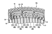
- FIG. 5 is an enlarged perspective view showing a part of the stator on the first end surface side.
- FIG. 6 is a plan view showing a part of the stator on the first end surface side.
- FIG. 7 is a perspective view showing a part of the stator on the first end surface side and a segment coil on the inner peripheral side in which the stator is double-rowed.
- FIG. 1 is a vertical sectional view showing a rotary electric machine according to the first embodiment.
- FIG. 2 is a cross-sectional view of the rotary electric machine according to the first embodiment.
- FIG. 8 is a perspective view showing a part of the stator on the second end surface side.
- FIG. 9 is a plan view showing a part of the front stator on the second end surface side.
- FIG. 10 is a diagram schematically showing a passing state of magnetic flux in a double-rowed coil segment.
- FIG. 11 is a perspective view showing a part of the stator according to the second embodiment on the first end face side and the segment coil on the inner peripheral side in which the stator is double-rowed.
- FIG. 12 is a plan view showing a part of the stator according to the second embodiment on the first end surface side.
- FIG. 13 is a perspective view showing a part of the stator on the first end face side and the segment coil on the inner peripheral side in which the stator is arranged in a row according to the third embodiment.
- FIG. 14 is a plan view showing a part of the stator according to the third embodiment on the first end surface side.
- FIG. 15 is a diagram schematically showing a part of a cross section of the stator and the divided segment according to the first modification.
- FIG. 16 is a diagram schematically showing a part of a cross section of the stator and the divided segment according to the second modification.
- FIG. 17 is a diagram schematically showing a part of the cross section of the stator and the divided segment according to the third modification.
- FIG. 1 is a vertical cross-sectional view of the rotary electric machine according to the first embodiment, and shows only one half of the rotary electric machine with the central axis C1 as the center.
- FIG. 2 is a cross-sectional view of the rotary electric machine.
- the rotary electric machine 10 is configured as, for example, a permanent magnet type rotary electric machine.
- the rotary electric machine 10 includes an annular or cylindrical stator 12, a rotor 14 that is rotatable inside the stator 12 around the central axis C1 and is coaxially supported with the stator 12, and these stators.
- a casing 30 for supporting the 12 and the rotor 14 is provided.
- the extending direction of the central axis C1 is referred to as an axial direction
- the direction of rotation around the central axis C1 is referred to as a circumferential direction
- the directions orthogonal to the axial direction and the circumferential direction are referred to as a radial direction.
- the stator 12 includes a cylindrical stator core 16 and a rotor winding (segment coil) 18 mounted on the stator core 16.
- the stator core 16 is formed by laminating a large number of annular electromagnetic steel plates 17 made of a magnetic material, for example, silicon steel, in a concentric manner. A large number of electrical steel sheets 17 are connected to each other in a laminated state by welding a plurality of locations on the outer peripheral surface of the stator core 16.
- the stator core 16 has a first end surface 16a located at one end in the axial direction and a second end surface 16b located at the other end in the axial direction. The first end surface 16a and the second end surface 16b extend orthogonally to the central axis C1.
- a plurality of (for example, 72) slots 20 are formed in the inner peripheral portion of the stator core 16.
- the plurality of slots 20 are arranged at equal intervals in the circumferential direction. It is also possible that the intervals in the circumferential direction of the plurality of slots 20 are not equal.
- Each slot 20 is opened on the inner peripheral surface of the stator core 16 and extends in the radial direction of the stator core 16 from the inner peripheral surface toward the outer peripheral surface.
- Each slot 20 extends over the entire length of the stator core 16 in the axial direction.
- One end of each slot 20 is open to the first end surface 16a, and the other end is open to the second end surface 16b.
- the slot 20 may be configured not to open on the inner peripheral surface of the stator core 16.
- the slot 20 may be formed as a through hole penetrating along the axial direction in the stator core 16.
- the inner peripheral portion of the stator core 16 constitutes a plurality of (for example, 72 in this embodiment) teeth 21 protruding toward the central axis C1.
- the teeth 21 are arranged at equal intervals along the circumferential direction.
- the stator core 16 integrally has an annular yoke portion and a plurality of teeth 21 projecting radially from the inner peripheral surface of the yoke portion toward the central axis C1.
- a slot 20 is formed between a pair of teeth 21 adjacent to each other in the circumferential direction.
- Coil 18 is embedded in a plurality of slots 20 and wound around each tooth 21.
- the coil 18 is provided so as to have coil ends 18a and 18b extending outward in the axial direction from the first end surface 16a and the second end surface 16b of the stator core 16. By passing an alternating current through the coil 18, a predetermined interlinkage magnetic flux is formed in the stator 12 (teeth 21).
- the casing 30 has a substantially cylindrical first bracket 32a and a bowl-shaped second bracket 32b.
- the first bracket 32a is connected to the iron core retainer 26 located on the drive end side of the stator core 16.
- the second bracket 32b is connected to the iron core retainer 26 located on the opposite drive end side.
- the first and second brackets 32a and 32b are made of, for example, an aluminum alloy or the like.
- An annular bearing bracket 34 is coaxially fastened to the tip end side of the first bracket 32a with bolts.
- a first bearing portion 36 containing a roller bearing 35 is fastened to the central portion of the bearing bracket 34.
- a second bearing portion 38 having a built-in ball bearing 37 is fastened to the central portion of the second bracket 32b, for example.
- the rotor 14 has a cylindrical shaft (rotating shaft) 42 rotatably supported around the central axis C1 by the first and second bearing portions 36, 38, and a substantially central portion in the axial direction of the shaft 42. It has a cylindrical rotor core 44 fixed to the rotor core 44, and a plurality of permanent magnets 46 embedded in the rotor core 44.
- the rotor core 44 is configured as a laminated body in which a large number of magnetic materials, for example, a large number of annular electromagnetic steel plates 47 such as silicon steel are laminated concentrically.
- the rotor core 44 has an inner hole 48 formed coaxially with the central axis C1.
- the shaft 42 is inserted and fitted into the inner hole 48 and extends coaxially with the rotor core 44.
- Approximately disk-shaped end plates 54 and iron core retainers 56 are provided at both ends of the rotor core 44 in the axial direction.
- the rotor core 44 is coaxially arranged with a slight gap (air gap) inside the stator core 16. That is, the outer peripheral surface of the rotor core 44 faces the inner peripheral surface (tip surface of the teeth 21) of the stator core 16 with a slight gap.
- the rotor core 44 is formed with a plurality of magnet embedding holes penetrating in the axial direction.
- a permanent magnet 46 is loaded and arranged in each magnet embedding hole, and is fixed to the rotor core 44 by, for example, an adhesive or the like. Each permanent magnet 46 extends over the entire length of the rotor core 44. Further, the plurality of permanent magnets 46 are arranged at predetermined intervals in the circumferential direction of the rotor core 44.
- the rotor core 44 has a d-axis extending in the radial direction or the radial direction of the rotor core 44, and a q-axis electrically separated from the d-axis by 90 °, respectively.
- the axis extending in the radial direction through the boundary between adjacent magnetic poles and the central axis C1 is defined as the q-axis
- the direction electrically perpendicular to the q-axis is defined as the d-axis.
- the d-axis and the q-axis are provided alternately in the circumferential direction of the rotor core 44 and in a predetermined phase.
- each permanent magnet 46 is formed in an elongated flat plate having a rectangular cross section, and has a length substantially equal to the axial length of the rotor core 44.
- the permanent magnets 46 are each inclined with respect to the d-axis.
- the two permanent magnets 46 are arranged side by side in a substantially V shape, for example.
- the ends of the permanent magnets 46 on the inner peripheral side are adjacent to the d-axis and face each other with a slight gap.
- the outer peripheral end of the permanent magnet 46 is separated from the d-axis along the circumferential direction of the rotor core 44, and is located near the outer peripheral surface of the rotor core 44 and near the q-axis. As a result, the outer peripheral end of the permanent magnet 46 is adjacent to the outer peripheral end of the permanent magnet 46 of the adjacent magnetic poles with the q-axis interposed therebetween.
- the rotor core 44 constitutes 12 magnetic poles arranged in the circumferential direction, and each magnetic pole includes two permanent magnets 46.
- the shape of the permanent magnet 46 is not limited to an elongated flat plate having a rectangular cross section, and various shapes can be used.
- FIG. 3 is a perspective view showing the first end face side of the stator
- FIG. 4 is a diagram schematically showing a part of a cross section of the stator and a divided segment.
- the stator 12 is driven by a three-phase (U-phase, V-phase and W-phase) AC power source.
- U-phase, V-phase and W-phase AC power source.
- a coil 18 corresponding to the U phase and connected in parallel a coil 18 corresponding to the V phase and connected in parallel
- a coil 18 corresponding to the W phase and connected in parallel are wound around the teeth 21 by a distributed arrangement. Has been done.
- the coil 18 includes three-phase (U, V, W) coils for each magnetic pole, and the coils for each phase are arranged in two of the six slots corresponding to one magnetic pole.
- the coils are not limited to those connected in parallel, and coils connected in series can also be used.
- Each coil 18 is composed of a segment coil formed by joining a plurality of coil segments formed of a flat conductor to each other.
- the flat conductor has a substantially rectangular shape in a cross section perpendicular to the longitudinal direction (cross section), or has at least two long sides facing each other in the shape of the cross section perpendicular to the longitudinal direction.
- cross section of the flat conductor is rectangular, the four corners do not have to be right angles and may be chamfered or rounded.
- the entire circumference of the flat conductor is covered with an insulating layer such as enamel, except for the conductive portion at the tip.
- each coil segment is located on the outside of the stator core 16 with the first linear portion and the second linear portion inserted and arranged in different slots 20 facing the second end surface 16b. It integrally has a bridge portion that connects the first linear portion and the second linear portion.
- the plurality of cross-linking portions constitute the coil end 18b.
- the first linear portion and the second linear portion each have an extending end portion extending outward from the first end surface 16a of the stator core 16. These extending ends are bent in the circumferential direction and form the coil end 18a of the coil 18.
- a plurality of, for example, four first linear portions or second linear portions are arranged in each slot 20, and the slots 20 are in a state where one sides of the rectangles face each other. They are arranged side by side in the radial direction of.
- the insulating sheet SP is wound around the four linear portions.
- the coil segment CS1 arranged on the innermost peripheral side of the slot 20 is composed of, for example, two divided segments DS1 and DS2.
- the divided segments DS1 and DS2 are formed of a flat conductor having a cross-sectional area of about half the cross-sectional area of the other coil segment CS, that is, a flat conductor thinner than the other coil segment CS.
- the divided segment DS1 is located on the outer side of the first linear portion LA1 and the second linear portion LA2 and the stator core 16 so as to face the second end surface 16b, and the first linear portion LA1.
- a cross-linking portion BA connecting the second linear portion LA2, and the cross-linking portion BA are integrally provided.
- the split segment DS2 is located on the outside of the stator core 16 with the first linear portion LB1 and the second linear portion LB2 facing the second end surface 16b, and the first linear portion LB1 and the second wire. It integrally has a cross-linked portion BB that connects the shaped portions LB2.
- the pair of first linear portions LA1 and LB1 are arranged in the slot 20 and are arranged in the first radial direction and adjacent to each other.
- the first linear portion LA1 is arranged adjacent to the innermost peripheral side of the slot 20, and the first linear portion LB1 is adjacent to the outer side in the radial direction of the first linear portion LA1.
- the second linear portions LA2 and LB2 are arranged in slots 20 separated from the first linear portions LA1 and LB1, for example, by five, and are adjacent to each other.
- the cross-linked portion BA and the cross-linked portion BB are arranged so as to intersect each other in the radial direction of the stator core 16.
- the arrangement relations of the second linear portions LA2 and LB2 are exchanged with those of the first linear portions LA1 and LB1, and the arrangement relations are reversed. That is, the second linear portions LA2 and LB2 are arranged side by side in the direction opposite to the first direction, the second linear portion LB2 is on the innermost peripheral side of the slot 20, and the second linear portion LA2 is the second line.
- the shape portion LB2 is arranged adjacent to the outside in the radial direction.
- the number of slots in which the second linear portions LA2 and LB2 are separated from the first linear portions LA1 and LB1 is not limited to five, and various values can be taken depending on the electrical design of the stator.
- FIG. 5 is an enlarged perspective view showing a part of the stator on the first end face side
- FIG. 6 is a plan view showing a part of the stator on the first end face side.
- the one-phase segment coil 18 sandwiches the first coil segment CS1 arranged on the innermost peripheral side of the slot 20 and the first coil segment CS1 from both sides in the circumferential direction.
- the first coil segment CS1 and the second coil segment CS2 are each double-rowed and are each composed of two divided segments.
- the U-phase first coil segment CS1 and the second coil segment CS2 are arranged side by side in two slots 20 adjacent to each other in the circumferential direction, and the V phase is placed in two slots 20 adjacent to these slots 20 in the circumferential direction.
- the first coil segment CS1 and the second coil segment CS2 of the above are arranged side by side.
- the first coil segment CS1 and the second coil segment CS2 of the W phase are placed.
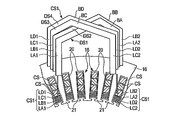
- FIG. 7 is a perspective view showing an arrangement configuration of the first coil segment CS1 and the second coil segment CS2 of one phase.
- the first coil segment CS1 is composed of divided segments (first divided segment, second divided segment) DS1 and DS2.
- the divided segment DS1 is located on the outer side of the stator core 16 with the first linear portion LA1 and the second linear portion LA2 facing the second end surface 16b, and the first linear portion LA1 and the second linear portion LA2. It integrally has a cross-linking portion BA that connects the above.
- the split segment DS2 is located on the outside of the stator core 16 with the first linear portion LB1 and the second linear portion LB2 facing the second end surface 16b, and the first linear portion LB1 and the second wire. It integrally has a cross-linked portion BB that connects the shaped portions LB2.
- the pair of first linear portions LA1 and LB1 of the first coil segment CS1 are arranged in the slot 20 and are arranged in the radial direction and adjacent to each other.
- the first linear portion LA1 is arranged adjacent to the innermost peripheral side of the slot 20, and the first linear portion LB1 is adjacent to the outer side in the radial direction of the first linear portion LA1.
- the extending end portion protruding from the second end surface 16 of the stator core 16 is bent inward in the radial direction of the stator core 16 and further axially. It is folded.
- the extending ends of the first linear portions LA1 and LB1 are positioned radially inward from the inner peripheral end of the slot 20, that is, from the inner peripheral of the stator core 16. ..
- the cross-linked portion BA of the divided segment DS1 extends from the extending end of the first linear portion LA1 along the circumferential direction of the stator core 16 substantially in parallel with the second end surface 16b, and the first section SA1 and the first section SA1.
- the first crank portion CR1 that inclines outward in the radial direction from the end and extends substantially parallel to the second end surface 16b, and the circumferential direction from the end of the first crank portion CR1 to the extending end of the second linear portion LA2. It has a second section SA2 extending along the same direction and substantially parallel to the second end surface 16b.
- the first crank portion CR1 is located substantially in the middle between the first linear portion LA1 and the second linear portion LA2.
- the cross-linked portion BA is formed by bending a flat conductor in a thickness direction or a direction orthogonal to the thickness direction without twisting.
- the second linear portion LA2 is arranged in the slot 20 five away from the first linear portion LA1. Since the cross-linking portion BA of the split segment DS1 is a portion connecting the split segments DS1 housed in slots 20 having different positions in the circumferential direction of the stator core 16, the first section SA1 and the second section SA2 are connected. Is not necessarily parallel to (or substantially parallel to) the second end surface 16b of the stator core 16, and can have various shapes.
- the cross-linked portion BA of the divided segment DS1 faces the second end surface 16b at a distance.
- the first section SA1 is located so as to be offset from the inner peripheral edge of the stator core 16 to the inner peripheral side.
- the second section SA2 is positioned on the outer side in the radial direction by about three times the thickness of the divided segment DS1 with respect to the first section SA1.
- the second linear portion LA2 is arranged in the slot 20 in a state of being displaced outward in the radial direction by one thickness with respect to the first linear portion LA1.
- the bridge portion BB of the divided segment DS2 is the first section SB1 extending substantially parallel to the second end surface 16b along the circumferential direction of the stator core 16 from the extending end of the first linear portion LB1 and the first section SB1.
- the second crank portion CR2 that inclines outward in the radial direction from the end and extends substantially parallel to the second end surface 16b, and the circumferential direction from the end of the second crank portion CR2 to the extending end of the second linear portion LB2. It has a second section SB2 extending along the same direction and substantially parallel to the second end surface 16b.
- the second crank portion CR2 is located substantially in the middle between the first linear portion LB1 and the second linear portion LB2.
- the cross-linked portion BB is formed by bending a flat conductor in a thickness direction or a direction orthogonal to the thickness direction without twisting.
- the second linear portion LB2 is arranged in the slot 20 five away from the first linear portion LB1. Since the bridge portion BB of the split segment DS2 is also a portion connecting the split segment DS2 housed in the slots 20 having different positions in the circumferential direction of the stator core 16, the first section SB1 and the second section
- the SB2 does not necessarily have to be parallel (or substantially parallel) to the second end surface 16b of the stator core 16, and may have various shapes.
- the first linear portion LB1 and the second linear portion LB2 are higher than the first linear portion LA1 and the second linear portion LA2 of the divided segment DS1 by almost twice the width of the flat conductor from the stator core 16. It extends in the axial direction.
- the cross-linked portion BB faces the second end surface 16b substantially in parallel with a larger interval than the cross-linked portion BA.
- the first section SB1 is located so as to be offset from the inner peripheral side end of the slot 20 to the inner peripheral side, and is substantially located on the inner peripheral edge of the stator core 16.
- first section SB1 is positioned so as to be offset outward in the radial direction by the thickness of the flat conductor with respect to the first section SA1 of the divided segment DS1, and is located above the axial direction by the width of the flat conductor (the first). 2 It is positioned so as to be offset from the end surface 16b).
- the second crank portion CR2 is located above the first crank portion CR1 in the axial direction, and extends so as to intersect the first crank portion CR1.
- the extension length (diametric height) (second length) of the second crank portion CR2 along the longitudinal direction of the flat conductor is the extension length (first length) of the first crank portion CR1. It is formed in less than half.
- the second section SB2 is positioned inward in the radial direction by the thickness of the flat conductor with respect to the second section SA2 of the divided segment DS1, and further upward by the width of the flat conductor (in the axial direction). It is positioned so as to be offset from the second end surface 16b).
- the second linear portion LB2 is located on the inner side in the radial direction with respect to the first linear portion LB1 and is arranged on the innermost peripheral side in the slot 20. In this way, the cross-linking portion BA of the split segment DS1 and the cross-linking portion BB of the split segment DS2 intersect and extend in the radial direction, and the positional relationship between the first linear portions LA1 and LB1 is in the second linear shape.
- the positional relationship between the parts LA2 and LB2 is reversed. That is, the first linear portion LA1 is located inside the first linear portion LB1 in the radial direction, and the second linear portion LA2 is located outside the radial portion with respect to the second linear portion LB2. There is.
- the second coil segment CS2 arranged so as to sandwich the first coil segment CS1 from both sides in the circumferential direction is composed of divided segments (third divided segment, fourth divided segment) DS3 and DS4.
- the split segment DS3 is located on the outer side of the stator core 16 with the first linear portion LC1 and the second linear portion LC2 facing the second end surface 16b, and the first linear portion LC1 and the second linear portion LC2. It has a bridged portion BC and a bridge portion BC which are connected to each other.
- the split segment DS4 is located on the outside of the stator core 16 with the first linear portion LD1 and the second linear portion LD2 facing the second end surface 16b, and the first linear portion LD1 and the second line. It integrally has a cross-linked portion BD that connects the shaped portions LD2.
- the pair of first linear portions LC1 and LD1 of the second coil segment CS2 is a slot adjacent to (outside the circumferential direction) of the slot 20 in which the first linear portions LA1 and LB1 of the first coil segment CS1 are arranged. They are arranged within 20 and are adjacent to each other side by side in the first radial direction.
- the first linear portion LC1 is arranged adjacent to the innermost peripheral side of the slot 20, and the first linear portion LD1 is adjacent to the outer side in the radial direction of the first linear portion LC1.
- the extending end portion protruding from the second end surface 16 of the stator core 16 is bent inward in the radial direction of the stator core 16 and further bent in the axial direction. ing.
- the extending ends of the first linear portions LC1 and LD1 are displaced inward in the radial direction from the inner peripheral end of the slot 20, that is, from the inner peripheral of the stator core 16. Is located.
- the bridged portion BC of the divided segment DS3 is a first section SC1 extending substantially parallel to the second end surface 16b along the circumferential direction of the stator core 16 from the extending end of the first linear portion LC1 and the first section SC1.
- a first crank portion (third crank portion) CR3 that inclines outward in the radial direction from the end and extends substantially parallel to the second end surface 16b, and an extension of the second linear portion LA2 from the end of the first crank portion CR3. It has a second section SC2 extending along the circumferential direction to the protruding end portion and substantially parallel to the second end surface 16b.
- the first crank portion CR3 is located substantially in the middle between the first linear portion LC1 and the second linear portion LC2.
- the cross-linked portion BC is formed by bending a flat conductor in a thickness direction or a direction orthogonal to the thickness direction without twisting.
- the second linear portion LC2 is a slot 20 seven away from the first linear portion LC1, that is, one of the slots 20 in which the second linear portions LA2 and LB2 of the first coil segment CS1 are arranged. It is arranged in the next slot 20 (outside in the circumferential direction).
- the number of slots in which the second linear portion LC2 is separated from the first linear portion LC1 is not limited to seven, and various values can be taken depending on the electrical design of the stator.
- the first linear portion LC1 and the second linear portion LC2 are higher than the first linear portion LA1 and the second linear portion LA2 of the divided segment DS1 by approximately the width of the rectangular conductor and are axially higher than the stator core 16. It is extended. As a result, the cross-linked portion BC faces the second end surface 16b substantially in parallel with a larger interval than the cross-linked portion BA. Since the bridge portion BC of the split segment DS3 is also a portion connecting the split segment DS3 housed in the slots 20 having different positions in the circumferential direction of the stator core 16, the first section SC1 and the second section The SC2 does not necessarily have to be parallel (or substantially parallel) to the second end surface 16b of the stator core 16, and may have various shapes.
- the first section SC1 of the bridge portion BC is located so as to be offset from the inner peripheral edge of the stator core 16 to the inner peripheral side.
- the second section SC2 is positioned with respect to the first section SC1 so as to be displaced outward in the radial direction by about three times the thickness of the divided segment DS3.
- the second linear portion LC2 is arranged in the slot 20 in a state of being displaced outward in the radial direction by one thickness with respect to the first linear portion LC1.
- the first section SC1, the first crank section CR3, and the second section SC2 of the bridge section BC are vertically overlapped with the first section SA1, the first crank section CR1, and the second section SA2 of the divided segment DS1, respectively. There is.
- the bridged portion BD of the divided segment DS4 has a first section SD1 extending substantially parallel to the second end surface 16b along the circumferential direction of the stator core 16 from the extending end of the first linear portion LD1 and the first section SD1.
- a second crank portion (fourth crank portion) CR4 that inclines outward in the radial direction from the end and extends substantially parallel to the second end surface 16b, and an extension of the second linear portion LD2 from the end of the second crank portion CR4. It has a second section SD2 extending along the circumferential direction to the protruding end portion and substantially parallel to the second end surface 16b.
- the second crank portion CR4 is located substantially in the middle between the first linear portion LD1 and the second linear portion LD2.
- the cross-linked portion BD is formed by bending a flat conductor in a thickness direction or a direction orthogonal to the thickness direction without twisting.
- the second linear portion LD2 is arranged in the slot 20 seven apart from the first linear portion LD1.
- the number of slots in which the second linear portion LD2 is separated from the first linear portion LD1 is not limited to seven, and various values can be taken depending on the electrical design of the stator.
- the bridge portion BD of the split segment DS4 is also a portion connecting the split segment DS4 housed in the slots 20 having different positions in the circumferential direction of the stator core 16, the first section SD1 and the second section The SD2 does not necessarily have to be parallel (or substantially parallel) to the second end surface 16b of the stator core 16, and may have various shapes.
- the first linear portion LD1 and the second linear portion LD2 are higher than the first linear portion LC1 and the second linear portion LC2 of the divided segment DS3 by almost twice the width of the rectangular conductor from the stator core 16. It extends in the axial direction.
- the cross-linked portion BD faces the second end surface 16b substantially in parallel with a larger interval than the cross-linked portion BC.
- the first section SD1 is located so as to be offset from the inner peripheral side end of the slot 20 to the inner peripheral side, and is substantially located on the inner peripheral edge of the stator core 16.
- first section SD1 is displaced outward in the radial direction by the thickness of the flat conductor with respect to the first section SC1 of the divided segment DS3, and is axially offset by twice the width of the flat conductor. It is located offset upward (in the direction away from the second end surface 16b).
- the second crank portion CR4 is located above the first crank portion CR3 in the axial direction, and extends so as to intersect the first crank portion CR3.
- the extension length (diameter height) of the second crank portion CR4 along the longitudinal direction of the flat conductor is formed to be half or less of the extension length of the first crank portion CR3.
- the second section SD2 is displaced inward in the radial direction by the thickness of the flat conductor with respect to the second section SC2 of the divided segment DS3, and further, in the axial direction by twice the width of the flat conductor. (Direction away from the second end surface 16b).
- the second linear portion LD2 is located on the inner side in the radial direction with respect to the first linear portion LC1 and is arranged on the innermost peripheral side in the slot 20.
- the first section SD1, the second crank portion CR4, and the second section SD2 of the bridge portion BD are arranged so as to overlap with each other in the axial direction on the first section SB1, the second crank portion CR2, and the second section SB2 of the divided segment DS2, respectively. There is.
- the cross-linking portion BC of the split segment DS3 and the cross-linking portion BD of the split segment DS4 intersect and extend in the radial direction, and the positional relationship between the first linear portions LC1 and LD1 is in the second linear shape.
- the positional relationship between the parts LD2 and LD2 is reversed. That is, the first linear portion LC1 is located inside the first linear portion LD1 in the radial direction, and the second linear portion LC2 is located outside the radial portion with respect to the second linear portion LD2.
- the second linear portions LC2 and LD2 are arranged side by side in the direction opposite to the first direction described above.
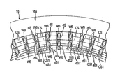
- FIG. 8 is a perspective view showing a part of the stator on the first end face side
- FIG. 9 is a plan view showing a part of the stator on the first end face side.
- the first linear portion and the second linear portion of the coil segment CS extend from the first end surface 16a to the outside of the stator core 16. It has an extension.
- Each of these extending portions is bent at a predetermined angle in the circumferential direction and extends at an angle with respect to the axial direction.
- the first linear portion and the second linear portion of the divided segments DS1 to DS4 each have an extending portion extending from the first end surface 16a to the outside of the stator core 16.
- Each of these extending portions is bent at a predetermined angle in the circumferential direction and extends at an angle with respect to the axial direction.
- the extending end of each extending end portion constitutes an end surface (joint surface) ds substantially parallel to the first end surface 16a.
- the extending portions of the four first or second linear portions inserted into each slot 20 are alternately bent in one direction and the opposite direction. That is, the extending portion of the first or second linear portion of the coil segment CS located on the outermost circumference is bent in one direction in the circumferential direction of the stator core 16, and the first or second coil segment CS on the inner side is bent. The extending portion of the second linear portion is bent in the other direction (reverse direction) in the circumferential direction. Further, the linear portion of the first or second linear portion of the coil segment CS on the inner side is bent in the one direction. Further, the extending portion of the first or second linear portion of the divided segments CS1 and CS2 located on the innermost circumference is bent in the other direction.
- each of the extension portions of the coil segments CS1 and CS2 on the innermost circumference includes two end faces ds1 and ds2 of the two divided segments.
- the end faces ds of the four extension portions in each row are welded to each other by two (two each) and are electrically conductive. That is, the end faces ds of the two extending portions on the outer peripheral side are welded to each other to form a weld bead WB straddling the two end face ds.
- the end faces ds of the two extending portions on the inner peripheral side are welded to each other to form a weld bead WB.
- the two end faces ds1 (or ds2) of the two split segments are joined to each other by welding, the split segments are electrically joined to each other, and the two end faces ds1 (or ds2) are adjacent to the coil segment CS.
- a weld bead WB straddling the three end faces ds, ds1, ds1 (or the three end faces ds, ds2, ds2) is formed.
- laser welding can be used for welding the end face ds of the extension portion.
- Each weld or joint of the coil segment is covered with an insulating material such as powder coating or varnish.
- a U-phase connection terminal TU, a V-phase connection terminal TV, and a W-phase connection terminal TW, which are not shown, are connected to three of the coils 18.
- This embodiment exemplifies a case where the number of parallel coils of the stator 12 is 2, and connection ends 8 are provided according to the number of parallel coils.
- a three-phase, 12-pole, 72-slot rotary electric machine is configured, the number of slots of the stator core 16 corresponding to one pole is 6 slots, and the coil of each phase is 1.
- the magnetic poles are arranged in two slots.
- the coil 18 by forming the coil 18 with a segment coil, the coil ends 18a and 18b protruding from the first end surface 16a and the second end surface 16b of the stator core 16 are projected.
- the height can be significantly reduced and the stator 12 can be downsized.
- the coil segments CS1 and CS2 located at least on the innermost circumference are double-rowed, and a plurality of divided segments DS1 made of a flat conductor having a thin wire diameter. It is composed of ⁇ DS4.
- the segment coils By arranging the segment coils on the innermost circumference in multiple rows, it is possible to suppress a decrease in the slot space utilization rate due to an increase in the number of conductors and maintain the effect of reducing loss at low speed rotation.
- the cross-sectional area of the conductor orthogonal to the magnetic flux traversing the slot 20 in the circumferential direction is reduced, and the eddy current generated in the conductor during high-speed rotation and the loss caused by the eddy current are reduced. can do.
- the double-rowed coil segment since both ends of the plurality of divided segments are welded to each other and electrically joined to each other, a closed circuit exists between the welding points in the double-rowed set of coils.
- FIG. 10 is a diagram schematically showing a passing state of magnetic flux in a double-rowed coil segment.
- FIG. 10A when the cross-linked portions of the two divided segments DS1 and DS2 are cross-linked and the welding points at both ends are dislocated, the loops between the welding points and the cross-linking positions are oriented in opposite directions. Magnetic flux will pass through. Therefore, as shown in FIG. 10B, the directions of the circulating currents I1 and I2 generated in one loop and the other loop are opposite to each other, and they act to cancel each other out. Therefore, the generation of circulating current is suppressed, and it becomes possible to prevent an increase in loss.
- the dislocation configuration that reverses the positional relationship between both ends is such that the split segments DS1 and DS2 are bent in the thickness direction or in the direction orthogonal to the thickness direction to form the first section SA1, SB1 and the second section SA2, SB2. It is obtained by changing the lane. Therefore, the segment coil can be easily manufactured and assembled as compared with the case of twisting.
- the first crank portion CR1 and CR3 and the second crank portion CR2 and CR4 of the cross-linking portion are in the circumferential direction. It is located directly above the slot located between the coil segments of the other phase adjacent to the coil segment of the other phase, and can be arranged in the vicinity of the coil segment of the other phase without interfering with the coil segment of the other phase. Therefore, it is possible to reduce the size and simplification of the coil end 18b.
- the first crank portions CR1 and CR3 having a long wire length are arranged below the second crank portions CR2 and CR3 having a short wire length, that is, on the stator core 16 side. Installation and assembly work of the coil segment can be facilitated. From the above, according to the present embodiment, it is possible to obtain a stator of a rotary electric machine capable of reducing the size and simplification of the coil end while suppressing the generation of eddy current.
- FIG. 11 is a perspective view showing an arrangement configuration of the first coil segment CS1 and the second coil segment CS2 of one phase of the stator according to the second embodiment
- FIG. 12 is a part of the stator on the first end surface side. It is a plan view which shows.
- the cross-linking portions BB and BD having the short crank portions CR2 and CR4 are stators.
- the iron cores 16 are arranged so as to overlap with each other in the axial direction, and the cross-linked portions BA and BC having the long crank portions CR1 and CR2 are arranged on these cross-linked portions.
- the cross-linked portions BA and BC are arranged so as to overlap each other in the radial direction of the stator core 16.
- the first coil segment CS1 is composed of the divided segments DS1 and DS2.
- the pair of first linear portions LA1 and LB1 of the first coil segment CS1 are arranged in the slot 20 and are arranged in the radial direction and adjacent to each other.
- the first linear portion LA1 is arranged adjacent to the innermost peripheral side of the slot 20, and the first linear portion LB1 is adjacent to the outer side in the radial direction of the first linear portion LA1.
- the extending end portion protruding from the second end surface 16 of the stator core 16 is bent inward in the radial direction of the stator core 16 and further axially. It is folded.
- the extending ends of the first linear portions LA1 and LB1 are positioned radially inward from the inner peripheral end of the slot 20, that is, from the inner peripheral of the stator core 16. ..
- the cross-linked portion BA of the divided segment DS1 extends from the extending end of the first linear portion LA1 along the circumferential direction of the stator core 16 substantially in parallel with the second end surface 16b, and the first section SA1 and the first section SA1.
- the first crank portion CR1 that inclines outward in the radial direction from the end and extends substantially parallel to the second end surface 16b, and the circumferential direction from the end of the first crank portion CR1 to the extending end of the second linear portion LA2. It has a second section SA2 extending along the same direction and substantially parallel to the second end surface 16b.
- the first crank portion CR1 is located substantially in the middle between the first linear portion LA1 and the second linear portion LA2.
- the cross-linked portion BA is formed by bending a flat conductor in a thickness direction or a direction orthogonal to the thickness direction without twisting.
- the second linear portion LA2 is arranged in the slot 20 five away from the first linear portion LA1.
- the cross-linked portion BA of the divided segment DS1 faces the second end surface 16b at a distance.
- the first section SA1 is located so as to be offset from the inner peripheral edge of the stator core 16 to the inner peripheral side.
- the second section SA2 is positioned on the outer side in the radial direction by about three times the thickness of the divided segment DS1 with respect to the first section SA1.
- the second linear portion LA2 is arranged in the slot 20 in a state of being displaced outward in the radial direction by one thickness with respect to the first linear portion LA1.
- the bridge portion BB of the divided segment DS2 is the first section SB1 extending substantially parallel to the second end surface 16b along the circumferential direction of the stator core 16 from the extending end of the first linear portion LB1 and the first section SB1.
- the second crank portion CR2 that inclines outward in the radial direction from the end and extends substantially parallel to the second end surface 16b, and the circumferential direction from the end of the second crank portion CR2 to the extending end of the second linear portion LB2. It has a second section SB2 extending along the same direction and substantially parallel to the second end surface 16b.
- the second crank portion CR2 is located substantially in the middle between the first linear portion LB1 and the second linear portion LB2.
- the cross-linked portion BB is formed by bending a flat conductor in a thickness direction or a direction orthogonal to the thickness direction without twisting.
- the second linear portion LB2 is arranged in the slot 20 five away from the first linear portion LB1.
- the first linear portion LB1 and the second linear portion LB2 are lower than the first linear portion LA1 and the second linear portion LA2 of the divided segment DS1 by almost twice the width of the flat conductor from the stator core 16. It extends in the axial direction.
- the cross-linked portion BB faces the second end surface 16b substantially in parallel with a space smaller than that of the cross-linked portion BA.
- the first section SB1 is located so as to be offset from the inner peripheral side end of the slot 20 to the inner peripheral side, and is substantially located on the inner peripheral edge of the stator core 16.
- first section SB1 is positioned so as to be offset outward in the radial direction by the thickness of the flat conductor with respect to the first section SA1 of the divided segment DS1, and is located downward in the axial direction by the width of the flat conductor (the first). 2 It is positioned so as to be offset in the direction approaching the end surface 16b).
- the second crank portion CR2 is positioned so as to overlap below the first crank portion CR1 in the axial direction, and extends so as to intersect the first crank portion CR1.
- the extension length (height in the radial direction) of the second crank portion CR2 along the longitudinal direction of the flat conductor is formed to be half or less of the extension length of the first crank portion CR1.
- the second section SB2 is positioned inward in the radial direction by the thickness of the flat conductor with respect to the second section SA2 of the divided segment DS1, and further downward by the width of the flat conductor (in the axial direction). It is positioned so as to be offset in the direction approaching the second end surface 16b).
- the second linear portion LB2 is located on the inner side in the radial direction with respect to the second linear portion LB1 and is arranged on the innermost peripheral side in the slot 20.
- the cross-linking portion BA of the split segment DS1 and the cross-linking portion BB of the split segment DS2 intersect and extend in the radial direction, and the positional relationship between the first linear portions LA1 and LB1 is in the second linear shape.
- the positional relationship between the parts LA2 and LB2 is reversed. That is, the first linear portion LA1 is located inside the first linear portion LB1 in the radial direction, and the second linear portion LA2 is located outside the radial portion with respect to the second linear portion LB2. There is.
- the second coil segment CS2 arranged so as to sandwich the first coil segment CS1 from both sides in the circumferential direction is composed of the divided segments DS3 and DS4.
- the pair of first linear portions LC1 and LD1 of the second coil segment CS2 is a slot adjacent to (outside the circumferential direction) of the slot 20 in which the first linear portions LA1 and LB1 of the first coil segment CS1 are arranged. They are arranged within 20 and are adjacent to each other in a radial direction.
- the first linear portion LC1 is arranged adjacent to the innermost peripheral side of the slot 20, and the first linear portion LD1 is adjacent to the outer side in the radial direction of the first linear portion LC1.
- the extending end portion protruding from the second end surface 16 of the stator core 16 is bent inward in the radial direction of the stator core 16 and further bent in the axial direction. ing.
- the extending ends of the first linear portions LC1 and LD1 are positioned radially inward from the inner peripheral end of the slot 20, that is, from the inner peripheral of the stator core 16. ..
- the extending end portion of the first linear portion LC1 is larger than the first linear portion LD1, and is located, for example, about three times the thickness of the first linear portion, offset inward in the radial direction. ..
- the bridged portion BC of the divided segment DS3 has a first section SC1 extending substantially parallel to the second end surface 16b along the circumferential direction of the stator core 16 from the extending end of the first linear portion LC1 and the first section SC1. Circumferential direction from the end of the first crank portion CR3 and the extending end of the second linear portion LA2, which is inclined outward from the end in the radial direction and extends substantially parallel to the second end surface 16b.
- the second section SC2 extending substantially parallel to the second end surface 16b, and provided in the middle of the second section SC2, inclined outward in the radial direction and extending substantially parallel to the second end surface 16b. It has a fifth crank portion CR5.
- the first crank portion CR3 is located substantially in the middle between the first linear portion LC1 and the second linear portion LC2.
- the extended length (height in the radial direction) of the first crank portion CR3 is formed to be about three times the thickness of the flat conductor.
- the radial extension length of the fifth crank portion CR5 is formed to be substantially equal to the thickness of the flat conductor.
- the cross-linked portion BC is formed by bending a flat conductor in a thickness direction or a direction orthogonal to the thickness direction without twisting.
- the second linear portion LC2 is adjacent to the slot 20 seven away from the first linear portion LC1, that is, the slot 20 in which the second linear portions LA2 and LB2 of the first coil segment CS1 are arranged ( It is arranged in the slot 20 (outside in the circumferential direction).
- the first linear portion LC1 and the second linear portion LC2 extend axially from the stator core 16 by a height substantially equal to that of the first linear portion LA1 and the second linear portion LA2 of the divided segment DS1.
- the cross-linked portion BC faces substantially parallel to the second end surface 16b at an interval equivalent to that of the cross-linked portion BA, and is further located radially inside the cross-linked portion BA and faces the cross-linked portion BA in the radial direction. ing.
- the first section SC1 of the cross-linked portion BC is located so as to be offset from the inner peripheral edge of the stator core 16 to the inner peripheral side.
- the second section SC2 is positioned with respect to the first section SC1 so as to be displaced outward in the radial direction by about three times the thickness of the divided segment DS3.
- the terminal portion of the second section SC2 is positioned so as to be further displaced outward in the radial direction by one thickness.
- the second linear portion LC2 is arranged in the slot 20 in a state of being displaced outward in the radial direction by one thickness with respect to the first linear portion LC1.
- the first section SC1, the first crank section CR3, and the second section SC2 of the bridge section BC are radially overlapped with the first section SA1, the first crank section CR1, and the second section SA2 of the divided segment DS1, respectively. There is.
- the bridged portion BD of the divided segment DS4 has a first section SD1 extending substantially parallel to the second end surface 16b along the circumferential direction of the stator core 16 from the extending end of the first linear portion LD1 and the first section SD1.
- the second crank portion CR4 that inclines outward in the radial direction from the end and extends substantially parallel to the second end surface 16b, and the circumferential direction from the end of the second crank portion CR4 to the extending end of the second linear portion LD2. It has a second section SD2 extending along the line and substantially parallel to the second end surface 16b.
- the second crank portion CR4 is located substantially in the middle between the first linear portion LD1 and the second linear portion LD2.
- the cross-linked portion BD is formed by bending a flat conductor in a thickness direction or a direction orthogonal to the thickness direction without twisting.
- the second linear portion LD2 is arranged in the slot 20 seven apart from the first linear portion LD1.
- the first linear portion LD1 and the second linear portion LD2 extend axially from the stator core 16 lower than the first linear portion LC1 and the second linear portion LC2 of the split segment DS3 by the width of the flat conductor. It is out.
- the cross-linked portion BD faces the second end surface 16b substantially in parallel with a space smaller than that of the cross-linked portion BC.
- the first section SD1 is located so as to be offset from the inner peripheral side end of the slot 20 to the inner peripheral side, and is substantially located on the inner peripheral edge of the stator core 16.
- first section SD1 is located so as to be displaced outward in the radial direction by three times the thickness of the flat conductor with respect to the first section SC1 of the divided segment DS3, and is axially displaced by the width of the flat conductor. It is located offset downward (in the direction approaching the second end surface 16b).
- the second crank portion CR4 is positioned so as to overlap below the first crank portion CR3 in the axial direction, and extends so as to intersect the first crank portion CR3.
- the extension length (height in the radial direction) of the second crank portion CR4 along the longitudinal direction of the flat conductor is formed to be about 1/3 of the extension length of the first crank portion CR3.
- the second section SD2 is located at the same radial position as the second section SC2 of the split segment DS3, and is further downward in the axial direction by the width of the flat conductor (direction approaching the second end surface 16b). It is located offset to. That is, the second section SD2 is located between the second section SB2 of the divided segment DS2 and the second section SC2 of the divided segment DS3, and is arranged so as to overlap in the axial direction. As a result, the second linear portion LD2 is located on the inner side in the radial direction with respect to the second linear portion LC1, and is arranged on the innermost peripheral side in the slot 20.
- the first section SD1, the second crank portion CR4, and the second section SD2 of the bridge portion BD are arranged so as to overlap with each other in the axial direction on the first section SB1, the second crank portion CR2, and the second section SB2 of the divided segment DS2, respectively. There is.
- the cross-linking portion BC of the split segment DS3 and the cross-linking portion BD of the split segment DS4 intersect and extend in the radial direction, and the positional relationship between the first linear portions LC1 and LD1 is in the second linear shape.
- the positional relationship between the parts LD2 and LD2 is reversed. That is, the first linear portion LC1 is located inside the first linear portion LD1 in the radial direction, and the second linear portion LC2 is located outside the radial portion with respect to the second linear portion LD2.
- the other configurations of the stator are the same as those in the first embodiment described above.
- the first section and the second section of the crosslinked portion of the divided segment do not necessarily have to be parallel (or substantially parallel) to the second end surface 16b of the stator core 16 and have various shapes. Can be.
- the dislocation configuration that reverses the positional relationship between both ends of the first coil segment CS1 and the second coil segment CS2 twists the divided segments DS1, DS2, DS3, and DS4. It is obtained by bending the first section SA1, SB1, SC1, SD1 and the second section SA2, SB2, SC2, SD2 by bending in the thickness direction or the direction orthogonal to the thickness direction. Therefore, the segment coil can be easily manufactured and assembled as compared with the case of twisting.
- the first crank portion CR1 and CR3 and the second crank portion CR2 and CR4 of the cross-linking portion are in the circumferential direction. It is located directly above the slot located between the coil segments of the other phase adjacent to the coil segment of the other phase, and can be arranged in the vicinity of the coil segment of the other phase without interfering with the coil segment of the other phase. Therefore, it is possible to reduce the size and simplification of the coil end 18b.
- the cross-linked portions BB and BD having the short crank portions CR2 and CR4 are in the axial direction of the stator core 16.
- cross-linking portions BA and BC having long crank portions CR1 and CR2 are arranged.
- the cross-linked portions BA and BC are arranged so as to overlap each other in the radial direction of the stator core 16. As a result, the extended height of the coil end can be reduced, and further miniaturization can be achieved. From the above, according to the second embodiment, it is possible to obtain a stator of a rotary electric machine capable of reducing the size and simplification of the coil end while suppressing the generation of eddy current.
- FIG. 13 is a perspective view showing an arrangement configuration of the first coil segment CS1 and the second coil segment CS2 of one phase of the stator according to the third embodiment
- FIG. 14 is a part of the stator on the first end surface side. It is a plan view which shows.
- the cross-linking portion BC of the split segment DS3 of the second coil segment CS2 is arranged so as to overlap the cross-linking portion BA of the split segment DS1 of the first coil segment CS1 in the radial direction of the stator core 16. Has been done.
- the cross-linking portion BC of the split segment DS3 is arranged so as to overlap the cross-linking portion BA of the split segment DS1 in the radial direction of the stator core 16.
- the first linear portion LC1 of the divided segment DS3 is arranged on the innermost peripheral side of the slot 20.
- the extending end portion protruding from the second end surface 16 of the stator core 16 is bent inward in the radial direction of the stator core 16 and further bent in the axial direction. ..
- the extending end portion of the first linear portion LC1 is positioned radially inward from the inner peripheral side end of the slot 20 by, for example, the thickness of the first linear portion.
- the bridged portion BC of the divided segment DS3 is a first section SC1 extending substantially parallel to the second end surface 16b along the circumferential direction of the stator core 16 from the extending end of the first linear portion LC1 and the first section SC1.
- It has a second section SC2 extending along the same direction and substantially parallel to the second end surface 16b.
- the first crank portion CR3 is located substantially in the middle between the first linear portion LC1 and the second linear portion LC2.
- the extended length (height in the radial direction) of the first crank portion CR3 is formed to be about three times the thickness of the flat conductor.
- the cross-linked portion BC is formed by bending a flat conductor in a thickness direction or a direction orthogonal to the thickness direction without twisting.
- the second linear portion LC2 is adjacent to the slot 20 seven away from the first linear portion LC1, that is, the slot 20 in which the second linear portions LA2 and LB2 of the first coil segment CS1 are arranged ( It is arranged in the slot 20 (outside in the circumferential direction).
- the first linear portion LC1 is higher than the first linear portion LA1 of the divided segment DS1 by the width of the flat conductor and extends axially from the stator core 16.
- the first section SC1, the first crank section CR3, and the second section SC2 of the bridge section BC are axial to the first section SA1, the first crank section CR1, and the second section SA2 of the bridge section BA of the split segment DS1, respectively. They are arranged so that they overlap in the direction.
- the other configurations of the first coil segment CS1 and the second coil segment CS2 are the same as those of the second embodiment described above.
- the first section and the second section of the crosslinked portion of the divided segment do not necessarily have to be parallel (or substantially parallel) to the second end surface 16b of the stator core 16, and may have various shapes. be able to.
- the dislocation configuration that reverses the positional relationship between both ends of the first coil segment CS1 and the second coil segment SC2 twists the divided segments DS1, DS2, DS3, and DS4.
- the segment coil can be easily manufactured and assembled as compared with the case of twisting.
- the first crank portion CR1 and CR3 and the second crank portion CR2 and CR4 of the cross-linking portion are in the circumferential direction. It is located directly above the slot located between the coil segments of the other phase adjacent to the coil segment of the other phase, and can be arranged in the vicinity of the coil segment of the other phase without interfering with the coil segment of the other phase.
- FIG. 15 schematically shows a part of the cross section of the stator and the divided segment according to the first modification.
- the coil segment CS1 arranged on the innermost peripheral side of the slot 20 is divided into three divided segments (first, second, and third divided segments) DS1, DS2, and DS3. It is divided and multi-columned.
- the divided segments DS1, DS2, and DS3 are formed by a flat conductor having a cross-sectional area of about 1/3 of the cross-sectional area of the other coil segment CS, that is, by a flat conductor thinner than the other coil segment CS. Has been done.
- the divided segment DS1 is located on the outer side of the stator core 16 with the first linear portion LA1 and the second linear portion LA2 facing the second end surface 16b, and the first linear portion LA1 and the second linear portion LA2. It integrally has a cross-linking portion BA that connects the above.
- the divided segment DS2 is located on the outside of the stator core 16 with the first linear portion LB1 and the second linear portion LB2 facing the second end surface 16b, and the first linear portion LB1 and the second linear portion LB2. It integrally has a cross-linking portion BB that connects the above.
- the split segment DS3 is located on the outside of the stator core 16 with the first linear portion LC1 and the second linear portion LC2 facing the second end surface 16b, and the first linear portion LC1 and the second wire. It integrally has a cross-linked portion BC that connects the shaped portions LC2.
- the three first linear portions LA1, LB1, and LC1 are arranged in the slot 20 and are arranged in the radial direction and adjacent to each other.
- the first linear portion LA1 is on the innermost peripheral side of the slot 20
- the first linear portion LB1 is on the radial outside of the first linear portion LA1
- the first linear portion LC1 is on the first linear portion. It is arranged adjacent to the outside of the radial direction of the LB1.
- the second linear portions LA2, LB2, and LC2 are arranged in slots 20 five apart from the first linear portions LA1, LB1, and LC1 and are adjacent to each other.
- the cross-linking portion BA is arranged so as to intersect the cross-linking portion BB in the radial direction of the stator core 16, and a part of the cross-linking portion BA is located outside the cross-linking portion BB in the radial direction.
- the cross-linking portion BC is arranged so as to intersect the cross-linking portion BB in the radial direction of the stator core 16, and a part of the cross-linking portion BC is located inside the cross-linking portion BB in the radial direction.
- the second linear portion LC2 is arranged adjacent to the innermost peripheral side of the slot 20, and the second linear portion LA2 is adjacent to the outer side in the radial direction of the second linear portion LC2 with the second linear portion LB2 interposed therebetween.
- Any of the configurations shown in the first, second, and third embodiments described above can be applied to the configurations of the cross-linked portions BA, BB, and BC.
- the cross-sectional area of the conductor orthogonal to the magnetic flux traversing the slot 20 in the circumferential direction is further reduced, and the eddy current generated in the conductor during high-speed rotation and the cause thereof. Loss can be reduced.
- the generation of circulating current can be suppressed by cross-linking the crosslinked portions of the three divided segments to dislocate the positional relationship between the first linear portion and the positional relationship of the second linear portion. Therefore, it is possible to reduce the loss by using the innermost coil which is double-rowed without causing a new loss increase factor.
- FIG. 16 schematically shows a part of the cross section of the stator and the divided segment according to the second modification.
- the coil segment CS1 arranged on the innermost peripheral side of the slot 20 has four divided segments (first, second, third, fourth divided segments) DS1 and D2. , D3, and D4 are divided into multiple rows.
- the divided segments DS1, DS2, and DS3 are formed of flat conductors having a cross-sectional area of about 1/4 of the cross-sectional area of the other coil segments CS.
- the divided segment DS4 is located on the outer side of the first linear portion LD1 and the second linear portion LD2 and the stator core 16 so as to face the second end surface 16b. It integrally has a cross-linked portion BD that connects the linear portion LD1 and the second linear portion LD2.
- the four first linear portions LA1, LB1, LC1, and LD1 are arranged in the slot 20 and are arranged radially and adjacent to each other.
- the first linear portion LA1 is located on the innermost peripheral side of the slot 20, and the first linear portions LB1, LC1, and LD1 are arranged in this order on the outer side thereof.
- the second linear portions LA2, LB2, LC2, and LD2 are arranged in slots 20 five apart from the first linear portions LA1, LB1, and LC1 and are adjacent to each other.
- the cross-linking portions BA and BB of the split segments DS1 and DS2 are arranged so as to intersect the split snow surface and the cross-linking portions BC and BD of the DS3 and DS4 in the radial direction of the stator core 16 and are one of the cross-linking portions BA and BB.
- the portion is located on the radial outer side of the cross-linked portions BC and BD.
- the second linear portions LA2, LB2 and the second linear portions LC2, LD2 are interchanged with the first linear portions LA1, LB1 and the first linear portions LC1, LD1 and have the opposite arrangement relation. It has become.
- the second linear portion LC2 is located on the innermost peripheral side of the slot 20, and the second linear portions LD2, LA2, and LB2 are arranged in this order on the outer side thereof.
- Any of the configurations shown in the first, second, and third embodiments described above can be applied to the configurations of the cross-linked portions BA, BB, BC, and BD.
- the cross-sectional area of the conductor orthogonal to the magnetic flux crossing the slot 20 in the circumferential direction is further reduced, and it is generated in the conductor at high speed rotation.
- the eddy current and the loss caused by this can be reduced.
- the generation of circulating current can be suppressed by cross-linking the crosslinked portions of the four divided segments to dislocate the positional relationship between the first linear portion and the positional relationship of the second linear portion. Therefore, it is possible to reduce the loss by using the innermost coil which is double-rowed without causing a new loss increase factor.
- FIG. 17 schematically shows a part of the cross section of the stator and the divided segment according to the third modification.
- the third modification in addition to the coil segment CS1 arranged on the innermost peripheral side of the slot 20, a plurality of coil segments CS4 arranged on the outermost peripheral side of the slot 20, for example, two.
- the division segments DS1 and DS2 are divided into multiple rows.
- the divided segments DS1 and DS2 are formed of flat conductors having a cross-sectional area of about 1 ⁇ 2 of the cross-sectional area of the other coil segments CS.
- the divided segment DS1 of the coil segment CS4 is located on the outer side of the first linear portion LA1 and the second linear portion LA2 and the stator core 16 so as to face the second end surface 16b, and the first linear portion LA1 and the second linear portion LA1 and the second. It integrally has a cross-linking portion BA that connects the linear portions LA2.
- the split segment DS2 is located on the outside of the stator core 16 with the first linear portion LB1 and the second linear portion LB2 facing the second end surface 16b, and the first linear portion LB1 and the second wire. It integrally has a cross-linked portion BB that connects the shaped portions LB2.
- the two first linear portions LA1 and LB1 are arranged in the slot 20 and are arranged in the radial direction and adjacent to each other.
- the first linear portion LB1 is arranged on the outermost peripheral side of the slot 20, and the first linear portion LA1 is arranged adjacent to the inside of the first linear portion LB1 in the radial direction.
- the second linear portions LA2 and LB2 are arranged in slots 20 five apart from the first linear portions LA1 and LB1 and are adjacent to each other.
- the cross-linking portion BA is arranged so as to intersect the cross-linking portion BB in the radial direction of the stator core 16, and a part of the cross-linking portion BA is located outside the cross-linking portion BB in the radial direction.
- the arrangement relations of the second linear portions LA2 and LB2 are exchanged with those of the first linear portions LA1 and LB1, and the arrangement relations are reversed. That is, the second linear portion LA2 is arranged adjacent to the outermost peripheral side of the slot 20, and the second linear portion LB2 is adjacent to the inside of the second linear portion LA2 in the radial direction.
- any of the configurations shown in the first, second, and third embodiments described above can be applied to the configurations of the cross-linked portions BA and BB. Further, as the configuration of the coil segment CS1, any of the configurations shown in the first, second, and third embodiments described above can be applied.
- the cross-sectional area of the conductor orthogonal to the magnetic flux crossing the slot 20 in the circumferential direction is further increased.
- the size can be reduced to reduce the eddy current generated in the conductor during high-speed rotation and the loss caused by the eddy current.
- the crosslinked portions of the two divided segments DS1 and DS2 are cross-linked so that the positional relationship of the first linear portion and the positional relationship of the second linear portion are dislocated. The generation of circulating current can be suppressed.
- the double rowing of the coil segments is not limited to two, and the double rowing may be performed by three or more divided segments.
Abstract
According to an embodiment, this stator comprises: a stator iron core 16 that has a plurality of slots 20; and multiphase segment coils that each have a plurality of coil segments having a first wiring section, a second wiring section, and a bridging section respectively disposed inside different slots, the plurality of coil segments being formed from rectangular conductors. At least coil segments CS1 disposed on the innermost circumferential side are configured by joining together a plurality of divided segments DS1, DS2 which respectively have first wiring sections LA1, LB1, second wiring sections LA2, LB2, and bridging sections BA, BB, the divided segments DS1, DS2 being formed from rectangular conductors having a cross-sectional area smaller than other coil segments. The bridging sections of the divided segments are disposed so as to cross each other in the radial direction. The first wiring sections are disposed inside the slots while being aligned in a first direction in the radial direction, and the second wiring sections are disposed inside the slots while being aligned in a direction opposite to the first direction.
Description
この発明の実施形態は、回転電機の固定子に関する。
An embodiment of the present invention relates to a stator of a rotary electric machine.
回転電機は、環状の固定子と、固定子の界磁領域に回転自在に設けられた回転子と、を備えている。固定子は、複数のスロットを有する環状の固定子鉄心と、固定子鉄心に装着された複数相の固定子コイルと、を有している。これらの固定子コイルは、複数のスロット内に配置された線状導体で構成されている。各スロットにおいて、複数本の線状導体が径方向に並んで配置されている。固定子コイルは、固定子鉄心の両端面から軸方向に突出するコイルエンドを有している。
近年、特に小型化の要求が高い移動体駆動用の回転電機の固定子では、平角導線から成るU字形状のコイル片(コイルセグメント)を固定子鉄心のスロットに挿入し、端部を捻り溶接することで成型されるセグメントコイルというコイル構成が採用されている。セグメントコイルを用いることで、細丸線を用いた固定子コイルに比べ、スロット内空間利用率の向上及びコイルエンドの縮小を図ることができる。素線径の太い平角導体を用いてセグメントコイルを構成することで、電気抵抗が低減され、低速回転時の低損失化が実現される。 The rotary electric machine includes an annular stator and a rotor rotatably provided in the field region of the stator. The stator has an annular stator core having a plurality of slots and a multi-phase stator coil mounted on the stator core. These stator coils are composed of linear conductors arranged in a plurality of slots. In each slot, a plurality of linear conductors are arranged side by side in the radial direction. The stator coil has coil ends that project axially from both end faces of the stator core.
In recent years, in the stator of a rotary electric machine for driving a moving body, which has a particularly high demand for miniaturization, a U-shaped coil piece (coil segment) made of a flat conductor is inserted into the slot of the stator core, and the end is twist-welded. A coil configuration called a segment coil, which is molded by doing so, is adopted. By using the segment coil, it is possible to improve the space utilization rate in the slot and reduce the coil end as compared with the stator coil using the fine round wire. By constructing the segment coil using a flat conductor with a large wire diameter, the electric resistance is reduced and the loss at low speed rotation is realized.
一方、高速回転時は導体を流れる電流や通過する磁束が高周波化するため、導体内に渦電流が誘導され、これに起因した損失の増加が懸念される。この対策として素線径の細い平角導線を複列化して用いることで損失増加を軽減できる。しかしながら、素線数増加に伴い絶縁物の体積が増加することで、スロット内の空間利用率が低下し、結果として低速回転時の損失低減効果を得られないなど、異なる回転数領域間での背反問題が介在していた。また、線状導体を複列化した場合、コイルにおける渦電流(還流電流)の発生を抑制するため、分割された複数本の線状導体の少なくとも一部に捻りを入れることで、複数本の線状導体の配設位置を転位する構成としている。
On the other hand, during high-speed rotation, the current flowing through the conductor and the magnetic flux passing through the conductor become high-frequency, so that an eddy current is induced in the conductor, and there is a concern that the loss due to this will increase. As a countermeasure, the increase in loss can be reduced by using multiple rows of flat conductors with a small wire diameter. However, as the volume of the insulator increases as the number of strands increases, the space utilization rate in the slot decreases, and as a result, the loss reduction effect at low speed rotation cannot be obtained. There was a conflict problem. In addition, when the linear conductors are double-rowed, in order to suppress the generation of eddy current (reflux current) in the coil, by twisting at least a part of the plurality of divided linear conductors, a plurality of linear conductors are arranged. The arrangement position of the linear conductor is changed.
上記のように構成された回転電機の固定子において、固定子コイルの少なくとも一部を複列化した場合、線状導体の引き回しが複雑になるとともに、捻りを入れることにより、コイルエンドの構成が複雑化する。
本発明の実施形態の課題は、コイルエンドの小型化および簡素化を図ることが可能な回転電機の固定子を提供することにある。 In the stator of a rotary electric machine configured as described above, when at least a part of the stator coils is double-rowed, the routing of the linear conductor becomes complicated and the coil end configuration is made by twisting. It gets complicated.
An object of the embodiment of the present invention is to provide a stator of a rotary electric machine capable of miniaturizing and simplifying a coil end.
実施形態によれば、回転電機の固定子は、中心軸線を有する環状のヨークと前記ヨークの内周から延出する複数のティースとを有し、隣合うティースの間にスロットが形成されている固定子鉄心と、異なるスロット内にそれぞれ配置された第1線状部および第2線状部と前記固定子鉄心の外方に位置し前記第1線状部および第2線状部を互いに連結した架橋部とを有し平角導体で形成された複数のコイルセグメントをそれぞれ有する複数相のセグメントコイルと、を備えている。前記中心軸線の方向を軸方向、前記中心軸線と直交する方向を径方向、前記中心軸線の周りの方向を周方向とした場合、前記スロット内に前記径方向に並んで複数本の第1線状部あるいは第2線状部が配置され、前記スロット内において少なくとも最も内周側に配置されているコイルセグメントは、それぞれ第1線状部および第2線状部と前記固定子鉄心の外方に位置し前記第1線状部および第2線状部を互いに連結した架橋部とを有し前記平角導体よりも断面積が小さい平角導体で形成された複数本の分割セグメントを互いに接合して構成されている。前記複数の分割セグメントの架橋部は、前記径方向に互いに交差して配置され、前記複数の分割セグメントの前記第1線状部は、前記スロット内において、前記径方向の第1方向に並んで配置され、前記第2線状部は、前記スロット内において前記第1方向と逆方向に並んで配置されている。
According to an embodiment, the stator of a rotary electric machine has an annular yoke having a central axis and a plurality of teeth extending from the inner circumference of the yoke, and a slot is formed between adjacent teeth. The stator core, the first and second linear portions arranged in different slots, and the first linear portion and the second linear portion located outside the stator core are connected to each other. It is provided with a multi-phase segment coil having a cross-linked portion and a plurality of coil segments each formed of a flat conductor. When the direction of the central axis is the axial direction, the direction orthogonal to the central axis is the radial direction, and the direction around the central axis is the circumferential direction, a plurality of first lines arranged in the radial direction in the slot. The coil segment in which the shape portion or the second linear portion is arranged and is arranged at least on the inner peripheral side in the slot is the outer side of the first linear portion and the second linear portion and the stator core, respectively. A plurality of divided segments formed of a flat conductor having a cross-sectional area smaller than that of the flat conductor, which has a bridge portion which is located at the center and connects the first linear portion and the second linear portion to each other, are joined to each other. It is configured. The crosslinked portions of the plurality of divided segments are arranged so as to intersect each other in the radial direction, and the first linear portions of the plurality of divided segments are arranged in the slot in the first radial direction. The second linear portion is arranged, and the second linear portion is arranged side by side in the slot in the direction opposite to the first direction.
以下に、図面を参照しながら、本発明の実施形態について説明する。なお、開示はあくまで一例にすぎず、当業者において、発明の主旨を保っての適宜変更について容易に想到し得るものについては、当然に本発明の範囲に含有されるものである。また、図面は説明をより明確にするため、実際の態様に比べ、各部の幅、厚さ、形状等について模式的に表される場合があるが、あくまで一例であって、本発明の解釈を限定するものではない。また、本明細書と各図において、既出の図に関して前述したものと同様の要素には、同一の符号を付して、詳細な説明を適宜省略することがある。
Hereinafter, embodiments of the present invention will be described with reference to the drawings. It should be noted that the disclosure is merely an example, and those skilled in the art can easily conceive of appropriate changes while maintaining the gist of the invention, which are naturally included in the scope of the present invention. Further, in order to clarify the explanation, the drawings may schematically represent the width, thickness, shape, etc. of each part as compared with the actual embodiment, but this is just an example, and the interpretation of the present invention is used. It is not limited. Further, in the present specification and each figure, the same elements as those described above with respect to the above-mentioned figures may be designated by the same reference numerals, and detailed description thereof may be omitted as appropriate.
(第1実施形態)
初めに、実施形態に係る固定子が適用される回転電機の一例について説明する。
図1は、第1実施形態に係る回転電機の縦断面図であり、中心軸線C1を中心として片側の半分だけを示している。図2は、回転電機の横断面図である。
図1に示すように、回転電機10は、例えば、永久磁石型の回転電機として構成されている。回転電機10は、環状あるいは円筒状の固定子12と、固定子12の内側に中心軸線C1の回りで回転自在に、かつ固定子12と同軸的に支持された回転子14と、これら固定子12および回転子14を支持するケーシング30と、を備えている。
以下の説明では、中心軸線C1の延在方向を軸方向、中心軸線C1回りに回転する方向を周方向、軸方向および周方向に直交する方向を径方向と称する。 (First Embodiment)
First, an example of a rotary electric machine to which the stator according to the embodiment is applied will be described.
FIG. 1 is a vertical cross-sectional view of the rotary electric machine according to the first embodiment, and shows only one half of the rotary electric machine with the central axis C1 as the center. FIG. 2 is a cross-sectional view of the rotary electric machine.
As shown in FIG. 1, the rotaryelectric machine 10 is configured as, for example, a permanent magnet type rotary electric machine. The rotary electric machine 10 includes an annular or cylindrical stator 12, a rotor 14 that is rotatable inside the stator 12 around the central axis C1 and is coaxially supported with the stator 12, and these stators. A casing 30 for supporting the 12 and the rotor 14 is provided.
In the following description, the extending direction of the central axis C1 is referred to as an axial direction, the direction of rotation around the central axis C1 is referred to as a circumferential direction, and the directions orthogonal to the axial direction and the circumferential direction are referred to as a radial direction.
初めに、実施形態に係る固定子が適用される回転電機の一例について説明する。
図1は、第1実施形態に係る回転電機の縦断面図であり、中心軸線C1を中心として片側の半分だけを示している。図2は、回転電機の横断面図である。
図1に示すように、回転電機10は、例えば、永久磁石型の回転電機として構成されている。回転電機10は、環状あるいは円筒状の固定子12と、固定子12の内側に中心軸線C1の回りで回転自在に、かつ固定子12と同軸的に支持された回転子14と、これら固定子12および回転子14を支持するケーシング30と、を備えている。
以下の説明では、中心軸線C1の延在方向を軸方向、中心軸線C1回りに回転する方向を周方向、軸方向および周方向に直交する方向を径方向と称する。 (First Embodiment)
First, an example of a rotary electric machine to which the stator according to the embodiment is applied will be described.
FIG. 1 is a vertical cross-sectional view of the rotary electric machine according to the first embodiment, and shows only one half of the rotary electric machine with the central axis C1 as the center. FIG. 2 is a cross-sectional view of the rotary electric machine.
As shown in FIG. 1, the rotary
In the following description, the extending direction of the central axis C1 is referred to as an axial direction, the direction of rotation around the central axis C1 is referred to as a circumferential direction, and the directions orthogonal to the axial direction and the circumferential direction are referred to as a radial direction.
図1および図2に示すように、固定子12は、円筒状の固定子鉄心16と固定子鉄心16に装着された回転子巻線(セグメントコイル)18とを備えている。固定子鉄心16は、磁性材、例えば、ケイ素鋼などの円環状の電磁鋼板17を多数枚、同芯状に積層して構成されている。多数枚の電磁鋼板17は、固定子鉄心16の外周面の複数個所を溶接することにより、互いに積層状態に連結されている。固定子鉄心16は、軸方向一端に位置する第1端面16a、および軸方向他端に位置する第2端面16bを有している。第1端面16aおよび第2端面16bは、中心軸線C1と直交して延在している。
As shown in FIGS. 1 and 2, the stator 12 includes a cylindrical stator core 16 and a rotor winding (segment coil) 18 mounted on the stator core 16. The stator core 16 is formed by laminating a large number of annular electromagnetic steel plates 17 made of a magnetic material, for example, silicon steel, in a concentric manner. A large number of electrical steel sheets 17 are connected to each other in a laminated state by welding a plurality of locations on the outer peripheral surface of the stator core 16. The stator core 16 has a first end surface 16a located at one end in the axial direction and a second end surface 16b located at the other end in the axial direction. The first end surface 16a and the second end surface 16b extend orthogonally to the central axis C1.
固定子鉄心16の内周部には、複数(例えば、72個)のスロット20が形成されている。本実施形態において、複数のスロット20は、円周方向に等間隔を置いて並んでいる。なお、複数のスロット20の円周方向の間隔については、等間隔でない構成とすることも可能である。各スロット20は、固定子鉄心16の内周面に開口し、固定子鉄心の径方向において、その内周面から外周面に向けた方向に延出している。各スロット20は、固定子鉄心16の軸方向の全長に亘って延在している。各スロット20の一端は第1端面16aに開口し、他端は第2端面16bに開口している。なお、スロット20は、固定子鉄心16の内周面に開口していない構成としてもよい。すなわち、スロット20は、固定子鉄心16において軸方向に沿って貫通する貫通孔として形成されてもよい。
複数のスロット20を形成することにより、固定子鉄心16の内周部は、中心軸線C1に向かって突出する複数(例えば、本実施形態では72個)のティース21を構成している。ティース21は、周方向に沿って等間隔を置いて配置されている。このように、固定子鉄心16は、円環状のヨーク部と、ヨーク部の内周面から中心軸線C1に向かって径方向に突出した複数のティース21とを一体に有している。周方向に隣合う一対のティース21の間にスロット20が形成されている。 A plurality of (for example, 72)slots 20 are formed in the inner peripheral portion of the stator core 16. In the present embodiment, the plurality of slots 20 are arranged at equal intervals in the circumferential direction. It is also possible that the intervals in the circumferential direction of the plurality of slots 20 are not equal. Each slot 20 is opened on the inner peripheral surface of the stator core 16 and extends in the radial direction of the stator core 16 from the inner peripheral surface toward the outer peripheral surface. Each slot 20 extends over the entire length of the stator core 16 in the axial direction. One end of each slot 20 is open to the first end surface 16a, and the other end is open to the second end surface 16b. The slot 20 may be configured not to open on the inner peripheral surface of the stator core 16. That is, the slot 20 may be formed as a through hole penetrating along the axial direction in the stator core 16.
By forming the plurality ofslots 20, the inner peripheral portion of the stator core 16 constitutes a plurality of (for example, 72 in this embodiment) teeth 21 protruding toward the central axis C1. The teeth 21 are arranged at equal intervals along the circumferential direction. As described above, the stator core 16 integrally has an annular yoke portion and a plurality of teeth 21 projecting radially from the inner peripheral surface of the yoke portion toward the central axis C1. A slot 20 is formed between a pair of teeth 21 adjacent to each other in the circumferential direction.
複数のスロット20を形成することにより、固定子鉄心16の内周部は、中心軸線C1に向かって突出する複数(例えば、本実施形態では72個)のティース21を構成している。ティース21は、周方向に沿って等間隔を置いて配置されている。このように、固定子鉄心16は、円環状のヨーク部と、ヨーク部の内周面から中心軸線C1に向かって径方向に突出した複数のティース21とを一体に有している。周方向に隣合う一対のティース21の間にスロット20が形成されている。 A plurality of (for example, 72)
By forming the plurality of
複数のスロット20にコイル18が埋め込まれ、各ティース21に巻き付けられている。コイル18は、固定子鉄心16の第1端面16aおよび第2端面16bから軸方向外側に向かって延出するコイルエンド18a、18bを有するように設けられている。コイル18に交流電流を流すことにより、固定子12(ティース21)に所定の鎖交磁束が形成される。
Coil 18 is embedded in a plurality of slots 20 and wound around each tooth 21. The coil 18 is provided so as to have coil ends 18a and 18b extending outward in the axial direction from the first end surface 16a and the second end surface 16b of the stator core 16. By passing an alternating current through the coil 18, a predetermined interlinkage magnetic flux is formed in the stator 12 (teeth 21).
図1に示すように、固定子鉄心16の軸方向両端には鉄心押え26が設けられている。
ケーシング30は、ほぼ円筒状の第1ブラケット32aと、お椀形状の第2ブラケット32bと、を有している。第1ブラケット32aは、固定子鉄心16の駆動端側に位置する鉄心押え26に連結されている。第2ブラケット32bは、反駆動端側に位置する鉄心押え26に連結されている。第1および第2ブラケット32a、32bは、例えば、アルミニウム合金等で形成されている。第1ブラケット32aの先端側に、環状のベアリングブラケット34がボルトにて同軸的に締結されている。ベアリングブラケット34の中央部に、例えば、ころ軸受35を内蔵した第1軸受部36が締結されている。第2ブラケット32bの中央部に、例えば玉軸受37を内蔵した第2軸受部38が締結されている。 As shown in FIG. 1,iron core retainers 26 are provided at both ends of the stator core 16 in the axial direction.
Thecasing 30 has a substantially cylindrical first bracket 32a and a bowl-shaped second bracket 32b. The first bracket 32a is connected to the iron core retainer 26 located on the drive end side of the stator core 16. The second bracket 32b is connected to the iron core retainer 26 located on the opposite drive end side. The first and second brackets 32a and 32b are made of, for example, an aluminum alloy or the like. An annular bearing bracket 34 is coaxially fastened to the tip end side of the first bracket 32a with bolts. For example, a first bearing portion 36 containing a roller bearing 35 is fastened to the central portion of the bearing bracket 34. A second bearing portion 38 having a built-in ball bearing 37 is fastened to the central portion of the second bracket 32b, for example.
ケーシング30は、ほぼ円筒状の第1ブラケット32aと、お椀形状の第2ブラケット32bと、を有している。第1ブラケット32aは、固定子鉄心16の駆動端側に位置する鉄心押え26に連結されている。第2ブラケット32bは、反駆動端側に位置する鉄心押え26に連結されている。第1および第2ブラケット32a、32bは、例えば、アルミニウム合金等で形成されている。第1ブラケット32aの先端側に、環状のベアリングブラケット34がボルトにて同軸的に締結されている。ベアリングブラケット34の中央部に、例えば、ころ軸受35を内蔵した第1軸受部36が締結されている。第2ブラケット32bの中央部に、例えば玉軸受37を内蔵した第2軸受部38が締結されている。 As shown in FIG. 1,
The
一方、回転子14は、第1および第2軸受部36、38により、中心軸線C1を中心に回転自在に支持された円柱形状のシャフト(回転軸)42と、シャフト42の軸方向ほぼ中央部に固定された円筒形状の回転子鉄心44と、回転子鉄心44内に埋め込まれた複数の永久磁石46と、を有している。回転子鉄心44は、磁性材、例えば、ケイ素鋼などの円環状の電磁鋼板47を多数枚、同芯状に積層した積層体として構成されている。回転子鉄心44は中心軸線C1と同軸的に形成された内孔48を有している。シャフト42は内孔48に挿通および嵌合され、回転子鉄心44と同軸的に延在している。回転子鉄心44の軸方向両端に、略円板状の端板54、鉄心押え56が設けられている。
On the other hand, the rotor 14 has a cylindrical shaft (rotating shaft) 42 rotatably supported around the central axis C1 by the first and second bearing portions 36, 38, and a substantially central portion in the axial direction of the shaft 42. It has a cylindrical rotor core 44 fixed to the rotor core 44, and a plurality of permanent magnets 46 embedded in the rotor core 44. The rotor core 44 is configured as a laminated body in which a large number of magnetic materials, for example, a large number of annular electromagnetic steel plates 47 such as silicon steel are laminated concentrically. The rotor core 44 has an inner hole 48 formed coaxially with the central axis C1. The shaft 42 is inserted and fitted into the inner hole 48 and extends coaxially with the rotor core 44. Approximately disk-shaped end plates 54 and iron core retainers 56 are provided at both ends of the rotor core 44 in the axial direction.
図1および図2に示すように、回転子鉄心44は、固定子鉄心16の内側に僅かな隙間(エアギャップ)を置いて同軸的に配置されている。すなわち、回転子鉄心44の外周面は、僅かな隙間をおいて、固定子鉄心16の内周面(ティース21の先端面)に対向している。
回転子鉄心44には、軸方向に貫通する複数の磁石埋め込み孔が形成されている。各磁石埋め込み孔内に永久磁石46が装填および配置され、例えば、接着剤等により回転子鉄心44に固定されている。各永久磁石46は、回転子鉄心44の全長に亘って延在している。また、複数の永久磁石46は、回転子鉄心44の周方向に所定の間隔を置いて配列されている。 As shown in FIGS. 1 and 2, therotor core 44 is coaxially arranged with a slight gap (air gap) inside the stator core 16. That is, the outer peripheral surface of the rotor core 44 faces the inner peripheral surface (tip surface of the teeth 21) of the stator core 16 with a slight gap.
Therotor core 44 is formed with a plurality of magnet embedding holes penetrating in the axial direction. A permanent magnet 46 is loaded and arranged in each magnet embedding hole, and is fixed to the rotor core 44 by, for example, an adhesive or the like. Each permanent magnet 46 extends over the entire length of the rotor core 44. Further, the plurality of permanent magnets 46 are arranged at predetermined intervals in the circumferential direction of the rotor core 44.
回転子鉄心44には、軸方向に貫通する複数の磁石埋め込み孔が形成されている。各磁石埋め込み孔内に永久磁石46が装填および配置され、例えば、接着剤等により回転子鉄心44に固定されている。各永久磁石46は、回転子鉄心44の全長に亘って延在している。また、複数の永久磁石46は、回転子鉄心44の周方向に所定の間隔を置いて配列されている。 As shown in FIGS. 1 and 2, the
The
図2に示すように、回転子鉄心44は、それぞれ回転子鉄心44の半径方向あるいは放射方向に延びるd軸、およびd軸に対して電気的に90°離間したq軸を有している。ここでは、隣合う磁極間の境界および中心軸線C1を通って放射方向に延びる軸をq軸とし、q軸に対して電気的に直角な方向をd軸としている。d軸およびq軸は、回転子鉄心44の円周方向に交互に、かつ、所定の位相で設けられている。
回転子鉄心44の円周方向において、各d軸の両側に2つの永久磁石46が配置されている。本実施形態において、各永久磁石46は、断面が矩形状の細長い平板状に形成され、回転子鉄心44の軸方向長さとほぼ等しい長さを有している。中心軸線C1と直交する回転子鉄心44の横断面でみた場合、永久磁石46は、それぞれd軸に対して傾斜している。2つの永久磁石46は、例えば、ほぼV字状に並んで配置されている。ここでは、永久磁石46の内周側の端はそれぞれd軸に隣接し、僅かな隙間をおいて互いに対向している。永久磁石46の外周側の端は、回転子鉄心44の円周方向に沿ってd軸から離間し、回転子鉄心44の外周面の近傍およびq軸の近傍に位置している。これにより、永久磁石46の外周側の端は、隣合う磁極の永久磁石46の外周側端と、q軸を挟んで隣接対向している。本実施形態において、回転子鉄心44は、円周方向に並んだ12磁極を構成し、各磁極は2つの永久磁石46を含んでいる。
なお、永久磁石46の形状は、断面が矩形状の細長い平板状に限定されることなく、種々の形状を用いることができる。 As shown in FIG. 2, therotor core 44 has a d-axis extending in the radial direction or the radial direction of the rotor core 44, and a q-axis electrically separated from the d-axis by 90 °, respectively. Here, the axis extending in the radial direction through the boundary between adjacent magnetic poles and the central axis C1 is defined as the q-axis, and the direction electrically perpendicular to the q-axis is defined as the d-axis. The d-axis and the q-axis are provided alternately in the circumferential direction of the rotor core 44 and in a predetermined phase.
Twopermanent magnets 46 are arranged on both sides of each d-axis in the circumferential direction of the rotor core 44. In the present embodiment, each permanent magnet 46 is formed in an elongated flat plate having a rectangular cross section, and has a length substantially equal to the axial length of the rotor core 44. When viewed in the cross section of the rotor core 44 orthogonal to the central axis C1, the permanent magnets 46 are each inclined with respect to the d-axis. The two permanent magnets 46 are arranged side by side in a substantially V shape, for example. Here, the ends of the permanent magnets 46 on the inner peripheral side are adjacent to the d-axis and face each other with a slight gap. The outer peripheral end of the permanent magnet 46 is separated from the d-axis along the circumferential direction of the rotor core 44, and is located near the outer peripheral surface of the rotor core 44 and near the q-axis. As a result, the outer peripheral end of the permanent magnet 46 is adjacent to the outer peripheral end of the permanent magnet 46 of the adjacent magnetic poles with the q-axis interposed therebetween. In the present embodiment, the rotor core 44 constitutes 12 magnetic poles arranged in the circumferential direction, and each magnetic pole includes two permanent magnets 46.
The shape of thepermanent magnet 46 is not limited to an elongated flat plate having a rectangular cross section, and various shapes can be used.
回転子鉄心44の円周方向において、各d軸の両側に2つの永久磁石46が配置されている。本実施形態において、各永久磁石46は、断面が矩形状の細長い平板状に形成され、回転子鉄心44の軸方向長さとほぼ等しい長さを有している。中心軸線C1と直交する回転子鉄心44の横断面でみた場合、永久磁石46は、それぞれd軸に対して傾斜している。2つの永久磁石46は、例えば、ほぼV字状に並んで配置されている。ここでは、永久磁石46の内周側の端はそれぞれd軸に隣接し、僅かな隙間をおいて互いに対向している。永久磁石46の外周側の端は、回転子鉄心44の円周方向に沿ってd軸から離間し、回転子鉄心44の外周面の近傍およびq軸の近傍に位置している。これにより、永久磁石46の外周側の端は、隣合う磁極の永久磁石46の外周側端と、q軸を挟んで隣接対向している。本実施形態において、回転子鉄心44は、円周方向に並んだ12磁極を構成し、各磁極は2つの永久磁石46を含んでいる。
なお、永久磁石46の形状は、断面が矩形状の細長い平板状に限定されることなく、種々の形状を用いることができる。 As shown in FIG. 2, the
Two
The shape of the
次に、固定子12の構成について詳細に説明する。
図3は、固定子の第1端面側を示す斜視図、図4は、固定子の断面の一部および分割セグメントを模式的に示す図である。
図3に示すように、固定子12は、3相(U相、V相およびW相)の交流電源によって駆動される。例えば、U相に対応し並列接続されたコイル18、V相に対応し並列接続されたコイル18、およびW相に対応し並列接続されたコイル18が、分布型の配置により、ティース21に巻き付けられている。すなわち、それぞれ並列接続されたU相、V相およびW相に対応する合計6本のコイル18が、ティース14に巻き付けられている。後述するように、コイル18は、各磁極に関して3相(U、V、W)のコイルを含み、各相のコイルは1磁極に対応する6スロットの内、2スロットに配置されている。なお、固定子12の各相において、コイルは並列接続したものに限らず、直列接続されたコイルを用いることも可能である。
各コイル18は、平角導体で形成された複数のコイルセグメントを互いに接合して一本に形成されたセグメントコイルで構成されている。平角導体は、長手方向に垂直な断面(横断面)が略矩形の形状をしているか、少なくとも、長手方向に垂直な断面の形状が対向する2長辺を有している。平角導体の横断面が矩形である場合、四隅は直角である必要はなく、面取りやR加工がされていてもよい。平角導体は、先端の導通部を除いて、ほぼ全周がエナメル等の絶縁層で覆われている。 Next, the configuration of thestator 12 will be described in detail.
FIG. 3 is a perspective view showing the first end face side of the stator, and FIG. 4 is a diagram schematically showing a part of a cross section of the stator and a divided segment.
As shown in FIG. 3, thestator 12 is driven by a three-phase (U-phase, V-phase and W-phase) AC power source. For example, a coil 18 corresponding to the U phase and connected in parallel, a coil 18 corresponding to the V phase and connected in parallel, and a coil 18 corresponding to the W phase and connected in parallel are wound around the teeth 21 by a distributed arrangement. Has been done. That is, a total of six coils 18 corresponding to the U phase, the V phase, and the W phase, which are connected in parallel, are wound around the teeth 14. As will be described later, the coil 18 includes three-phase (U, V, W) coils for each magnetic pole, and the coils for each phase are arranged in two of the six slots corresponding to one magnetic pole. In each phase of the stator 12, the coils are not limited to those connected in parallel, and coils connected in series can also be used.
Eachcoil 18 is composed of a segment coil formed by joining a plurality of coil segments formed of a flat conductor to each other. The flat conductor has a substantially rectangular shape in a cross section perpendicular to the longitudinal direction (cross section), or has at least two long sides facing each other in the shape of the cross section perpendicular to the longitudinal direction. When the cross section of the flat conductor is rectangular, the four corners do not have to be right angles and may be chamfered or rounded. The entire circumference of the flat conductor is covered with an insulating layer such as enamel, except for the conductive portion at the tip.
図3は、固定子の第1端面側を示す斜視図、図4は、固定子の断面の一部および分割セグメントを模式的に示す図である。
図3に示すように、固定子12は、3相(U相、V相およびW相)の交流電源によって駆動される。例えば、U相に対応し並列接続されたコイル18、V相に対応し並列接続されたコイル18、およびW相に対応し並列接続されたコイル18が、分布型の配置により、ティース21に巻き付けられている。すなわち、それぞれ並列接続されたU相、V相およびW相に対応する合計6本のコイル18が、ティース14に巻き付けられている。後述するように、コイル18は、各磁極に関して3相(U、V、W)のコイルを含み、各相のコイルは1磁極に対応する6スロットの内、2スロットに配置されている。なお、固定子12の各相において、コイルは並列接続したものに限らず、直列接続されたコイルを用いることも可能である。
各コイル18は、平角導体で形成された複数のコイルセグメントを互いに接合して一本に形成されたセグメントコイルで構成されている。平角導体は、長手方向に垂直な断面(横断面)が略矩形の形状をしているか、少なくとも、長手方向に垂直な断面の形状が対向する2長辺を有している。平角導体の横断面が矩形である場合、四隅は直角である必要はなく、面取りやR加工がされていてもよい。平角導体は、先端の導通部を除いて、ほぼ全周がエナメル等の絶縁層で覆われている。 Next, the configuration of the
FIG. 3 is a perspective view showing the first end face side of the stator, and FIG. 4 is a diagram schematically showing a part of a cross section of the stator and a divided segment.
As shown in FIG. 3, the
Each
後述するように、各コイルセグメントは、それぞれ異なるスロット20に挿入、配置される第1線状部および第2線状部と、固定子鉄心16の外側に第2端面16bと対向して位置し第1線状部および第2線状部を連結する架橋部と、を一体に有している。複数の架橋部はコイルエンド18bを構成している。第1線状部および第2線状部は、それぞれ固定子鉄心16の第1端面16aから固定子鉄心16の外方に延出した延出端部を有している。これらの延出端部は、周方向に折り曲げられているとともに、コイル18のコイルエンド18aを構成している。
As will be described later, each coil segment is located on the outside of the stator core 16 with the first linear portion and the second linear portion inserted and arranged in different slots 20 facing the second end surface 16b. It integrally has a bridge portion that connects the first linear portion and the second linear portion. The plurality of cross-linking portions constitute the coil end 18b. The first linear portion and the second linear portion each have an extending end portion extending outward from the first end surface 16a of the stator core 16. These extending ends are bent in the circumferential direction and form the coil end 18a of the coil 18.
図2および図4に示すように、各スロット20の中に複数本、例えば、4本の第1線状部あるいは第2線状部が配置され、矩形の一辺同士が対向した状態でスロット20の径方向に並んで配置されている。スロット20内において、4つの線状部の周囲に絶縁シートSPが巻かれている。4つのコイルセグメントCSの内、少なくとも1つのコイルセグメントは、複数に分割され複列化されている。本実施形態では、スロット20の最内周側に配置されたコイルセグメントCS1は、例えば、2つの分割セグメントDS1、DS2で構成されている。分割セグメントDS1、DS2は、他のコイルセグメントCSの横断面の面積の約半分程度の横断面積を有する平角導体により、すなわち、他のコイルセグメントCSとよりも細い平角導体により、形成されている。
As shown in FIGS. 2 and 4, a plurality of, for example, four first linear portions or second linear portions are arranged in each slot 20, and the slots 20 are in a state where one sides of the rectangles face each other. They are arranged side by side in the radial direction of. In the slot 20, the insulating sheet SP is wound around the four linear portions. Of the four coil segments CS, at least one coil segment is divided into a plurality of coils and arranged in a plurality of rows. In the present embodiment, the coil segment CS1 arranged on the innermost peripheral side of the slot 20 is composed of, for example, two divided segments DS1 and DS2. The divided segments DS1 and DS2 are formed of a flat conductor having a cross-sectional area of about half the cross-sectional area of the other coil segment CS, that is, a flat conductor thinner than the other coil segment CS.
図4に示すように、分割セグメントDS1は、第1線状部LA1および第2線状部LA2と、固定子鉄心16の外側に第2端面16bと対向して位置し第1線状部LA1および第2線状部LA2を連結する架橋部BAと、を一体に有している。同様に、分割セグメントDS2は、第1線状部LB1および第2線状部LB2と、固定子鉄心16の外側に第2端面16bと対向して位置し第1線状部LB1および第2線状部LB2を連結する架橋部BBと、を一体に有している。
As shown in FIG. 4, the divided segment DS1 is located on the outer side of the first linear portion LA1 and the second linear portion LA2 and the stator core 16 so as to face the second end surface 16b, and the first linear portion LA1. And a cross-linking portion BA connecting the second linear portion LA2, and the cross-linking portion BA are integrally provided. Similarly, the split segment DS2 is located on the outside of the stator core 16 with the first linear portion LB1 and the second linear portion LB2 facing the second end surface 16b, and the first linear portion LB1 and the second wire. It integrally has a cross-linked portion BB that connects the shaped portions LB2.
一対の第1線状部LA1、LB1はスロット20内に配置され径方向の第1方向に並んで互いに隣接している。例えば、第1線状部LA1がスロット20の最内周側に、第1線状部LB1が第1線状部LA1の径方向の外側に隣接して配置されている。第2線状部LA2、LB2は、第1線状部LA1、LB1から、例えば、5つ離れたスロット20に配置され互いに隣接している。ここで、架橋部BAおよび架橋部BBは、固定子鉄心16の径方向に互いに交差して配置されている。これにより、第2線状部LA2、LB2は、第1線状部LA1、LB1と配置関係が入れ代わり、逆の配置関係となっている。すなわち、第2線状部LA2、LB2は上記第1方向と逆方向に並んで配置され、第2線状部LB2がスロット20の最内周側に、第2線状部LA2が第2線状部LB2の径方向の外側に隣接して配置されている。
なお、第2線状部LA2、LB2が第1線状部LA1、LB1から離れるスロット数は、5つに限らず、固定子の電気設計に応じて種々の値をとることが可能である。 The pair of first linear portions LA1 and LB1 are arranged in theslot 20 and are arranged in the first radial direction and adjacent to each other. For example, the first linear portion LA1 is arranged adjacent to the innermost peripheral side of the slot 20, and the first linear portion LB1 is adjacent to the outer side in the radial direction of the first linear portion LA1. The second linear portions LA2 and LB2 are arranged in slots 20 separated from the first linear portions LA1 and LB1, for example, by five, and are adjacent to each other. Here, the cross-linked portion BA and the cross-linked portion BB are arranged so as to intersect each other in the radial direction of the stator core 16. As a result, the arrangement relations of the second linear portions LA2 and LB2 are exchanged with those of the first linear portions LA1 and LB1, and the arrangement relations are reversed. That is, the second linear portions LA2 and LB2 are arranged side by side in the direction opposite to the first direction, the second linear portion LB2 is on the innermost peripheral side of the slot 20, and the second linear portion LA2 is the second line. The shape portion LB2 is arranged adjacent to the outside in the radial direction.
The number of slots in which the second linear portions LA2 and LB2 are separated from the first linear portions LA1 and LB1 is not limited to five, and various values can be taken depending on the electrical design of the stator.
なお、第2線状部LA2、LB2が第1線状部LA1、LB1から離れるスロット数は、5つに限らず、固定子の電気設計に応じて種々の値をとることが可能である。 The pair of first linear portions LA1 and LB1 are arranged in the
The number of slots in which the second linear portions LA2 and LB2 are separated from the first linear portions LA1 and LB1 is not limited to five, and various values can be taken depending on the electrical design of the stator.
図5は、前記固定子の第1端面側の一部を拡大して示す斜視図、図6は、前記固定子の第1端面側の一部を示す平面図である。
図5および図6に示すように、1相のセグメントコイル18は、スロット20の最内周側に配置された第1コイルセグメントCS1と、第1コイルセグメントCS1を周方向の両側から挟むように配置されスロット20の最内周側に配置された第2コイルセグメントCS2と、を含んでいる。第1コイルセグメントCS1および第2コイルセグメントCS2は、それぞれ複列化され、それぞれ2つの分割セグメントで構成されている。
一例では、U相の第1コイルセグメントCS1および第2コイルセグメントCS2が周方向に隣合う2つのスロット20に並んで配置され、これらのスロット20に周方向に隣接する2つのスロット20にV相の第1コイルセグメントCS1および第2コイルセグメントCS2が並んで配置されている。更に、V相の第1、第2コイルセグメントCS1、CS2が配置されている2つのスロット20に周方向に隣接する2つのスロット20に、W相の第1コイルセグメントCS1および第2コイルセグメントCS2が並んで配置されている。このように、スロット20の最内周側において、U相コイルセグメント、V相コイルセグメント、W相コイルセグメントが2本ずつ周方向に順に並んで配置されている。 FIG. 5 is an enlarged perspective view showing a part of the stator on the first end face side, and FIG. 6 is a plan view showing a part of the stator on the first end face side.
As shown in FIGS. 5 and 6, the one-phase segment coil 18 sandwiches the first coil segment CS1 arranged on the innermost peripheral side of the slot 20 and the first coil segment CS1 from both sides in the circumferential direction. The second coil segment CS2, which is arranged and arranged on the innermost peripheral side of the slot 20, is included. The first coil segment CS1 and the second coil segment CS2 are each double-rowed and are each composed of two divided segments.
In one example, the U-phase first coil segment CS1 and the second coil segment CS2 are arranged side by side in twoslots 20 adjacent to each other in the circumferential direction, and the V phase is placed in two slots 20 adjacent to these slots 20 in the circumferential direction. The first coil segment CS1 and the second coil segment CS2 of the above are arranged side by side. Further, in the two slots 20 adjacent to the two slots 20 in which the first and second coil segments CS1 and CS2 of the V phase are arranged in the circumferential direction, the first coil segment CS1 and the second coil segment CS2 of the W phase are placed. Are arranged side by side. In this way, on the innermost peripheral side of the slot 20, two U-phase coil segments, two V-phase coil segments, and two W-phase coil segments are arranged in order in the circumferential direction.
図5および図6に示すように、1相のセグメントコイル18は、スロット20の最内周側に配置された第1コイルセグメントCS1と、第1コイルセグメントCS1を周方向の両側から挟むように配置されスロット20の最内周側に配置された第2コイルセグメントCS2と、を含んでいる。第1コイルセグメントCS1および第2コイルセグメントCS2は、それぞれ複列化され、それぞれ2つの分割セグメントで構成されている。
一例では、U相の第1コイルセグメントCS1および第2コイルセグメントCS2が周方向に隣合う2つのスロット20に並んで配置され、これらのスロット20に周方向に隣接する2つのスロット20にV相の第1コイルセグメントCS1および第2コイルセグメントCS2が並んで配置されている。更に、V相の第1、第2コイルセグメントCS1、CS2が配置されている2つのスロット20に周方向に隣接する2つのスロット20に、W相の第1コイルセグメントCS1および第2コイルセグメントCS2が並んで配置されている。このように、スロット20の最内周側において、U相コイルセグメント、V相コイルセグメント、W相コイルセグメントが2本ずつ周方向に順に並んで配置されている。 FIG. 5 is an enlarged perspective view showing a part of the stator on the first end face side, and FIG. 6 is a plan view showing a part of the stator on the first end face side.
As shown in FIGS. 5 and 6, the one-
In one example, the U-phase first coil segment CS1 and the second coil segment CS2 are arranged side by side in two
図7は、1相の第1コイルセグメントCS1および第2コイルセグメントCS2の配置構成を示す斜視図である。
図示のように、第1コイルセグメントCS1は、分割セグメント(第1分割セグメント、第2分割セグメント)DS1、DS2で構成されている。分割セグメントDS1は、第1線状部LA1および第2線状部LA2と、固定子鉄心16の外側に第2端面16bと対向して位置し第1線状部LA1および第2線状部LA2を連結する架橋部BAと、を一体に有している。同様に、分割セグメントDS2は、第1線状部LB1および第2線状部LB2と、固定子鉄心16の外側に第2端面16bと対向して位置し第1線状部LB1および第2線状部LB2を連結する架橋部BBと、を一体に有している。 FIG. 7 is a perspective view showing an arrangement configuration of the first coil segment CS1 and the second coil segment CS2 of one phase.
As shown in the figure, the first coil segment CS1 is composed of divided segments (first divided segment, second divided segment) DS1 and DS2. The divided segment DS1 is located on the outer side of thestator core 16 with the first linear portion LA1 and the second linear portion LA2 facing the second end surface 16b, and the first linear portion LA1 and the second linear portion LA2. It integrally has a cross-linking portion BA that connects the above. Similarly, the split segment DS2 is located on the outside of the stator core 16 with the first linear portion LB1 and the second linear portion LB2 facing the second end surface 16b, and the first linear portion LB1 and the second wire. It integrally has a cross-linked portion BB that connects the shaped portions LB2.
図示のように、第1コイルセグメントCS1は、分割セグメント(第1分割セグメント、第2分割セグメント)DS1、DS2で構成されている。分割セグメントDS1は、第1線状部LA1および第2線状部LA2と、固定子鉄心16の外側に第2端面16bと対向して位置し第1線状部LA1および第2線状部LA2を連結する架橋部BAと、を一体に有している。同様に、分割セグメントDS2は、第1線状部LB1および第2線状部LB2と、固定子鉄心16の外側に第2端面16bと対向して位置し第1線状部LB1および第2線状部LB2を連結する架橋部BBと、を一体に有している。 FIG. 7 is a perspective view showing an arrangement configuration of the first coil segment CS1 and the second coil segment CS2 of one phase.
As shown in the figure, the first coil segment CS1 is composed of divided segments (first divided segment, second divided segment) DS1 and DS2. The divided segment DS1 is located on the outer side of the
第1コイルセグメントCS1の一対の第1線状部LA1、LB1はスロット20内に配置され径方向に並んで互いに隣接している。例えば、第1線状部LA1がスロット20の最内周側に、第1線状部LB1が第1線状部LA1の径方向の外側に隣接して配置されている。第1線状部LA1、LB1において、固定子鉄心16の第2端面16から突出するしている延出端部は、固定子鉄心16の径方向の内側に折曲げられ、更に、軸方向に折り曲げられている。これにより、第1線状部LA1、LB1の延出端部は、スロット20の内周側端よりも、すなわち、固定子鉄心16の内周よりも、径方向内側にずれて位置している。
The pair of first linear portions LA1 and LB1 of the first coil segment CS1 are arranged in the slot 20 and are arranged in the radial direction and adjacent to each other. For example, the first linear portion LA1 is arranged adjacent to the innermost peripheral side of the slot 20, and the first linear portion LB1 is adjacent to the outer side in the radial direction of the first linear portion LA1. In the first linear portions LA1 and LB1, the extending end portion protruding from the second end surface 16 of the stator core 16 is bent inward in the radial direction of the stator core 16 and further axially. It is folded. As a result, the extending ends of the first linear portions LA1 and LB1 are positioned radially inward from the inner peripheral end of the slot 20, that is, from the inner peripheral of the stator core 16. ..
分割セグメントDS1の架橋部BAは、第1線状部LA1の延出端から固定子鉄心16の周方向に沿って第2端面16bとほぼ平行に延びる第1区間SA1と、第1区間SA1の終端から径方向の外方に向かって傾斜し第2端面16bとほぼ平行に延びる第1クランク部CR1と、第1クランク部CR1の終端から第2線状部LA2の延出端部まで周方向に沿って、かつ、第2端面16bとほぼ平行に延びる第2区間SA2と、を有している。第1クランク部CR1は、第1線状部LA1と第2線状部LA2との間のほぼ中間に位置している。架橋部BAは、平角導体を捩じることなく、厚さ方向あるいは厚さ方向と直交する方向に折り曲げることで形成されている。一例では、第2線状部LA2は、第1線状部LA1から5つ離れたスロット20内に配置されている。
なお、分割セグメントDS1の架橋部BAは、固定子鉄心16の周方向の位置が異なるスロット20内に収納される分割セグメントDS1を接続する部分であることから、第1区間SA1や第2区間SA2を必ずしも固定子鉄心16の第2端面16bに平行(またはほぼ平行)としなくても構わず、種々の形状とすることができる。
分割セグメントDS1の架橋部BAは、第2端面16bと間隔を置いて対向している。第1区間SA1は、固定子鉄心16の内周縁よりも内周側にずれて位置している。第1クランク部CR1を設けることにより、第2区間SA2は、第1区間SA1に対して、径方向の外側に分割セグメントDS1の厚さの約3倍分だけ、ずれて位置している。これにより、第2線状部LA2は、第1線状部LA1に対して、厚さ1枚分だけ径方向の外側にずれた状態でスロット20内に配置されている。 The cross-linked portion BA of the divided segment DS1 extends from the extending end of the first linear portion LA1 along the circumferential direction of thestator core 16 substantially in parallel with the second end surface 16b, and the first section SA1 and the first section SA1. The first crank portion CR1 that inclines outward in the radial direction from the end and extends substantially parallel to the second end surface 16b, and the circumferential direction from the end of the first crank portion CR1 to the extending end of the second linear portion LA2. It has a second section SA2 extending along the same direction and substantially parallel to the second end surface 16b. The first crank portion CR1 is located substantially in the middle between the first linear portion LA1 and the second linear portion LA2. The cross-linked portion BA is formed by bending a flat conductor in a thickness direction or a direction orthogonal to the thickness direction without twisting. In one example, the second linear portion LA2 is arranged in the slot 20 five away from the first linear portion LA1.
Since the cross-linking portion BA of the split segment DS1 is a portion connecting the split segments DS1 housed inslots 20 having different positions in the circumferential direction of the stator core 16, the first section SA1 and the second section SA2 are connected. Is not necessarily parallel to (or substantially parallel to) the second end surface 16b of the stator core 16, and can have various shapes.
The cross-linked portion BA of the divided segment DS1 faces thesecond end surface 16b at a distance. The first section SA1 is located so as to be offset from the inner peripheral edge of the stator core 16 to the inner peripheral side. By providing the first crank portion CR1, the second section SA2 is positioned on the outer side in the radial direction by about three times the thickness of the divided segment DS1 with respect to the first section SA1. As a result, the second linear portion LA2 is arranged in the slot 20 in a state of being displaced outward in the radial direction by one thickness with respect to the first linear portion LA1.
なお、分割セグメントDS1の架橋部BAは、固定子鉄心16の周方向の位置が異なるスロット20内に収納される分割セグメントDS1を接続する部分であることから、第1区間SA1や第2区間SA2を必ずしも固定子鉄心16の第2端面16bに平行(またはほぼ平行)としなくても構わず、種々の形状とすることができる。
分割セグメントDS1の架橋部BAは、第2端面16bと間隔を置いて対向している。第1区間SA1は、固定子鉄心16の内周縁よりも内周側にずれて位置している。第1クランク部CR1を設けることにより、第2区間SA2は、第1区間SA1に対して、径方向の外側に分割セグメントDS1の厚さの約3倍分だけ、ずれて位置している。これにより、第2線状部LA2は、第1線状部LA1に対して、厚さ1枚分だけ径方向の外側にずれた状態でスロット20内に配置されている。 The cross-linked portion BA of the divided segment DS1 extends from the extending end of the first linear portion LA1 along the circumferential direction of the
Since the cross-linking portion BA of the split segment DS1 is a portion connecting the split segments DS1 housed in
The cross-linked portion BA of the divided segment DS1 faces the
分割セグメントDS2の架橋部BBは、第1線状部LB1の延出端から固定子鉄心16の周方向に沿って第2端面16bとほぼ平行に延びる第1区間SB1と、第1区間SB1の終端から径方向の外方に向かって傾斜し第2端面16bとほぼ平行に延びる第2クランク部CR2と、第2クランク部CR2の終端から第2線状部LB2の延出端部まで周方向に沿って、かつ、第2端面16bとほぼ平行に延びる第2区間SB2と、を有している。第2クランク部CR2は、第1線状部LB1と第2線状部LB2との間のほぼ中間に位置している。架橋部BBは、平角導体を捩じることなく、厚さ方向あるいは厚さ方向と直交する方向に折り曲げることで形成されている。一例では、第2線状部LB2は、第1線状部LB1から5つ離れたスロット20内に配置されている。
なお、分割セグメントDS2の架橋部BBについても、固定子鉄心16の周方向の位置が異なるスロット20内に収納される分割セグメントDS2を接続する部分であることから、第1区間SB1や第2区間SB2を必ずしも固定子鉄心16の第2端面16bに平行(またはほぼ平行)としなくても構わず、種々の形状とすることができる。 The bridge portion BB of the divided segment DS2 is the first section SB1 extending substantially parallel to thesecond end surface 16b along the circumferential direction of the stator core 16 from the extending end of the first linear portion LB1 and the first section SB1. The second crank portion CR2 that inclines outward in the radial direction from the end and extends substantially parallel to the second end surface 16b, and the circumferential direction from the end of the second crank portion CR2 to the extending end of the second linear portion LB2. It has a second section SB2 extending along the same direction and substantially parallel to the second end surface 16b. The second crank portion CR2 is located substantially in the middle between the first linear portion LB1 and the second linear portion LB2. The cross-linked portion BB is formed by bending a flat conductor in a thickness direction or a direction orthogonal to the thickness direction without twisting. In one example, the second linear portion LB2 is arranged in the slot 20 five away from the first linear portion LB1.
Since the bridge portion BB of the split segment DS2 is also a portion connecting the split segment DS2 housed in theslots 20 having different positions in the circumferential direction of the stator core 16, the first section SB1 and the second section The SB2 does not necessarily have to be parallel (or substantially parallel) to the second end surface 16b of the stator core 16, and may have various shapes.
なお、分割セグメントDS2の架橋部BBについても、固定子鉄心16の周方向の位置が異なるスロット20内に収納される分割セグメントDS2を接続する部分であることから、第1区間SB1や第2区間SB2を必ずしも固定子鉄心16の第2端面16bに平行(またはほぼ平行)としなくても構わず、種々の形状とすることができる。 The bridge portion BB of the divided segment DS2 is the first section SB1 extending substantially parallel to the
Since the bridge portion BB of the split segment DS2 is also a portion connecting the split segment DS2 housed in the
第1線状部LB1および第2線状部LB2は、分割セグメントDS1の第1線状部LA1および第2線状部LA2よりも平角導体の幅のほぼ2倍分だけ高く固定子鉄心16から軸方向に延出している。これにより、架橋部BBは、架橋部BAよりも大きな間隔を置いて第2端面16bとほぼ平行に対向している。第1区間SB1は、スロット20の内周側端よりも内周側にずれて位置し、ほぼ固定子鉄心16の内周縁の上に位置している。また、第1区間SB1は、分割セグメントDS1の第1区間SA1に対し、平角導体の厚さ分だけ径方向の外側にずれて位置し、かつ、平角導体の幅分だけ軸方向の上方(第2端面16bから離れる方向)にずれて位置している。第2クランク部CR2は、軸方向において第1クランク部CR1の上方に重なって位置し、かつ、第1クランク部CR1と交差して延びている。平角導体の長手方向に沿った第2クランク部CR2の延出長さ(径方向の高さ)(第2長さ)は、第1クランク部CR1の延出長さ(第1長さ)の半分以下に形成されている。これにより、第2区間SB2は、分割セグメントDS1の第2区間SA2に対し、平角導体の厚さ分だけ径方向の内側にずれて位置し、更に、平角導体の幅分だけ軸方向の上方(第2端面16bから離れる方向)にずれて位置している。第2線状部LB2は、第1線状部LB1に対して径方向の内側に位置し、スロット20内において、最内周側に配置されている。
このようにして、分割セグメントDS1の架橋部BAと分割セグメントDS2の架橋部BBとは、径方向に交差して延在し、第1線状部LA1、LB1の位置関係が、第2線状部LA2、LB2の位置関係と逆転している。すなわち、第1線状部LA1は第1線状部LB1に対して径方向の内側に位置し、第2線状部LA2は第2線状部LB2に対して径方向の外側に位置している。 The first linear portion LB1 and the second linear portion LB2 are higher than the first linear portion LA1 and the second linear portion LA2 of the divided segment DS1 by almost twice the width of the flat conductor from thestator core 16. It extends in the axial direction. As a result, the cross-linked portion BB faces the second end surface 16b substantially in parallel with a larger interval than the cross-linked portion BA. The first section SB1 is located so as to be offset from the inner peripheral side end of the slot 20 to the inner peripheral side, and is substantially located on the inner peripheral edge of the stator core 16. Further, the first section SB1 is positioned so as to be offset outward in the radial direction by the thickness of the flat conductor with respect to the first section SA1 of the divided segment DS1, and is located above the axial direction by the width of the flat conductor (the first). 2 It is positioned so as to be offset from the end surface 16b). The second crank portion CR2 is located above the first crank portion CR1 in the axial direction, and extends so as to intersect the first crank portion CR1. The extension length (diametric height) (second length) of the second crank portion CR2 along the longitudinal direction of the flat conductor is the extension length (first length) of the first crank portion CR1. It is formed in less than half. As a result, the second section SB2 is positioned inward in the radial direction by the thickness of the flat conductor with respect to the second section SA2 of the divided segment DS1, and further upward by the width of the flat conductor (in the axial direction). It is positioned so as to be offset from the second end surface 16b). The second linear portion LB2 is located on the inner side in the radial direction with respect to the first linear portion LB1 and is arranged on the innermost peripheral side in the slot 20.
In this way, the cross-linking portion BA of the split segment DS1 and the cross-linking portion BB of the split segment DS2 intersect and extend in the radial direction, and the positional relationship between the first linear portions LA1 and LB1 is in the second linear shape. The positional relationship between the parts LA2 and LB2 is reversed. That is, the first linear portion LA1 is located inside the first linear portion LB1 in the radial direction, and the second linear portion LA2 is located outside the radial portion with respect to the second linear portion LB2. There is.
このようにして、分割セグメントDS1の架橋部BAと分割セグメントDS2の架橋部BBとは、径方向に交差して延在し、第1線状部LA1、LB1の位置関係が、第2線状部LA2、LB2の位置関係と逆転している。すなわち、第1線状部LA1は第1線状部LB1に対して径方向の内側に位置し、第2線状部LA2は第2線状部LB2に対して径方向の外側に位置している。 The first linear portion LB1 and the second linear portion LB2 are higher than the first linear portion LA1 and the second linear portion LA2 of the divided segment DS1 by almost twice the width of the flat conductor from the
In this way, the cross-linking portion BA of the split segment DS1 and the cross-linking portion BB of the split segment DS2 intersect and extend in the radial direction, and the positional relationship between the first linear portions LA1 and LB1 is in the second linear shape. The positional relationship between the parts LA2 and LB2 is reversed. That is, the first linear portion LA1 is located inside the first linear portion LB1 in the radial direction, and the second linear portion LA2 is located outside the radial portion with respect to the second linear portion LB2. There is.
第1コイルセグメントCS1を周方向の両側から挟むように配置された第2コイルセグメントCS2は、分割セグメント(第3分割セグメント、第4分割セグメント)DS3、DS4で構成されている。分割セグメントDS3は、第1線状部LC1および第2線状部LC2と、固定子鉄心16の外側に第2端面16bと対向して位置し第1線状部LC1および第2線状部LC2を連結した架橋部BCと、を一体に有している。同様に、分割セグメントDS4は、第1線状部LD1および第2線状部LD2と、固定子鉄心16の外側に第2端面16bと対向して位置し第1線状部LD1および第2線状部LD2を連結する架橋部BDと、を一体に有している。
The second coil segment CS2 arranged so as to sandwich the first coil segment CS1 from both sides in the circumferential direction is composed of divided segments (third divided segment, fourth divided segment) DS3 and DS4. The split segment DS3 is located on the outer side of the stator core 16 with the first linear portion LC1 and the second linear portion LC2 facing the second end surface 16b, and the first linear portion LC1 and the second linear portion LC2. It has a bridged portion BC and a bridge portion BC which are connected to each other. Similarly, the split segment DS4 is located on the outside of the stator core 16 with the first linear portion LD1 and the second linear portion LD2 facing the second end surface 16b, and the first linear portion LD1 and the second line. It integrally has a cross-linked portion BD that connects the shaped portions LD2.
第2コイルセグメントCS2の一対の第1線状部LC1、LD1は、第1コイルセグメントCS1の第1線状部LA1、LB1が配置されているスロット20の1つ隣り(周方向外側)のスロット20の内に配置され、径方向の第1方向に並んで互いに隣接している。例えば、第1線状部LC1がスロット20の最内周側に、第1線状部LD1が第1線状部LC1の径方向の外側に隣接して配置されている。第1線状部LC1、LD1において、固定子鉄心16の第2端面16から突出している延出端部は、固定子鉄心16の径方向の内側に折曲げられ、更に、軸方向に折り曲げられている。これにより、本実施形態では、第1線状部LC1、LD1の延出端部は、スロット20の内周側端よりも、すなわち、固定子鉄心16の内周よりも、径方向内側にずれて位置している。
The pair of first linear portions LC1 and LD1 of the second coil segment CS2 is a slot adjacent to (outside the circumferential direction) of the slot 20 in which the first linear portions LA1 and LB1 of the first coil segment CS1 are arranged. They are arranged within 20 and are adjacent to each other side by side in the first radial direction. For example, the first linear portion LC1 is arranged adjacent to the innermost peripheral side of the slot 20, and the first linear portion LD1 is adjacent to the outer side in the radial direction of the first linear portion LC1. In the first linear portions LC1 and LD1, the extending end portion protruding from the second end surface 16 of the stator core 16 is bent inward in the radial direction of the stator core 16 and further bent in the axial direction. ing. As a result, in the present embodiment, the extending ends of the first linear portions LC1 and LD1 are displaced inward in the radial direction from the inner peripheral end of the slot 20, that is, from the inner peripheral of the stator core 16. Is located.
分割セグメントDS3の架橋部BCは、第1線状部LC1の延出端から固定子鉄心16の周方向に沿って第2端面16bとほぼ平行に延びる第1区間SC1と、第1区間SC1の終端から径方向の外方に向かって傾斜し第2端面16bとほぼ平行に延びる第1クランク部(第3クランク部)CR3と、第1クランク部CR3の終端から第2線状部LA2の延出端部まで周方向に沿って、かつ、第2端面16bとほぼ平行に延びる第2区間SC2と、を有している。第1クランク部CR3は、第1線状部LC1と第2線状部LC2との間のほぼ中間に位置している。架橋部BCは、平角導体を捩じることなく、厚さ方向あるいは厚さ方向と直交する方向に折り曲げることで形成されている。一例では、第2線状部LC2は、第1線状部LC1から7つ離れたスロット20、すなわち、第1コイルセグメントCS1の第2線状部LA2、LB2が配置されているスロット20の1つ隣り(周方向外側)のスロット20、内に配置されている。なお、第2線状部LC2が第1線状部LC1から離れるスロット数は7つに限らず、固定子の電気設計に応じて種々の値を取りうる。
第1線状部LC1および第2線状部LC2は、分割セグメントDS1の第1線状部LA1および第2線状部LA2よりも平角導体のほぼ幅分だけ高く固定子鉄心16から軸方向に延出している。これにより、架橋部BCは、架橋部BAよりも大きな間隔を置いて第2端面16bとほぼ平行に対向している。
なお、分割セグメントDS3の架橋部BCについても、固定子鉄心16の周方向の位置が異なるスロット20内に収納される分割セグメントDS3を接続する部分であることから、第1区間SC1や第2区間SC2を必ずしも固定子鉄心16の第2端面16bに平行(またはほぼ平行)としなくても構わず、種々の形状とすることができる。 The bridged portion BC of the divided segment DS3 is a first section SC1 extending substantially parallel to thesecond end surface 16b along the circumferential direction of the stator core 16 from the extending end of the first linear portion LC1 and the first section SC1. A first crank portion (third crank portion) CR3 that inclines outward in the radial direction from the end and extends substantially parallel to the second end surface 16b, and an extension of the second linear portion LA2 from the end of the first crank portion CR3. It has a second section SC2 extending along the circumferential direction to the protruding end portion and substantially parallel to the second end surface 16b. The first crank portion CR3 is located substantially in the middle between the first linear portion LC1 and the second linear portion LC2. The cross-linked portion BC is formed by bending a flat conductor in a thickness direction or a direction orthogonal to the thickness direction without twisting. In one example, the second linear portion LC2 is a slot 20 seven away from the first linear portion LC1, that is, one of the slots 20 in which the second linear portions LA2 and LB2 of the first coil segment CS1 are arranged. It is arranged in the next slot 20 (outside in the circumferential direction). The number of slots in which the second linear portion LC2 is separated from the first linear portion LC1 is not limited to seven, and various values can be taken depending on the electrical design of the stator.
The first linear portion LC1 and the second linear portion LC2 are higher than the first linear portion LA1 and the second linear portion LA2 of the divided segment DS1 by approximately the width of the rectangular conductor and are axially higher than thestator core 16. It is extended. As a result, the cross-linked portion BC faces the second end surface 16b substantially in parallel with a larger interval than the cross-linked portion BA.
Since the bridge portion BC of the split segment DS3 is also a portion connecting the split segment DS3 housed in theslots 20 having different positions in the circumferential direction of the stator core 16, the first section SC1 and the second section The SC2 does not necessarily have to be parallel (or substantially parallel) to the second end surface 16b of the stator core 16, and may have various shapes.
第1線状部LC1および第2線状部LC2は、分割セグメントDS1の第1線状部LA1および第2線状部LA2よりも平角導体のほぼ幅分だけ高く固定子鉄心16から軸方向に延出している。これにより、架橋部BCは、架橋部BAよりも大きな間隔を置いて第2端面16bとほぼ平行に対向している。
なお、分割セグメントDS3の架橋部BCについても、固定子鉄心16の周方向の位置が異なるスロット20内に収納される分割セグメントDS3を接続する部分であることから、第1区間SC1や第2区間SC2を必ずしも固定子鉄心16の第2端面16bに平行(またはほぼ平行)としなくても構わず、種々の形状とすることができる。 The bridged portion BC of the divided segment DS3 is a first section SC1 extending substantially parallel to the
The first linear portion LC1 and the second linear portion LC2 are higher than the first linear portion LA1 and the second linear portion LA2 of the divided segment DS1 by approximately the width of the rectangular conductor and are axially higher than the
Since the bridge portion BC of the split segment DS3 is also a portion connecting the split segment DS3 housed in the
架橋部BCの第1区間SC1は、固定子鉄心16の内周縁よりも内周側にずれて位置している。第1クランク部CR3を設けることにより、第2区間SC2は、第1区間SC1に対して、分割セグメントDS3の厚さの約3倍分だけ径方向の外側にずれて位置している。これにより、第2線状部LC2は、第1線状部LC1に対して、厚さ1枚分だけ径方向の外側にずれた状態でスロット20内に配置されている。架橋部BCの第1区間SC1、第1クランク部CR3、第2区間SC2は、それぞれ分割セグメントDS1の第1区間SA1、第1クランク部CR1、第2区間SA2に軸方向に重なって配置されている。
The first section SC1 of the bridge portion BC is located so as to be offset from the inner peripheral edge of the stator core 16 to the inner peripheral side. By providing the first crank portion CR3, the second section SC2 is positioned with respect to the first section SC1 so as to be displaced outward in the radial direction by about three times the thickness of the divided segment DS3. As a result, the second linear portion LC2 is arranged in the slot 20 in a state of being displaced outward in the radial direction by one thickness with respect to the first linear portion LC1. The first section SC1, the first crank section CR3, and the second section SC2 of the bridge section BC are vertically overlapped with the first section SA1, the first crank section CR1, and the second section SA2 of the divided segment DS1, respectively. There is.
分割セグメントDS4の架橋部BDは、第1線状部LD1の延出端から固定子鉄心16の周方向に沿って第2端面16bとほぼ平行に延びる第1区間SD1と、第1区間SD1の終端から径方向の外方に向かって傾斜し第2端面16bとほぼ平行に延びる第2クランク部(第4クランク部)CR4と、第2クランク部CR4の終端から第2線状部LD2の延出端部まで周方向に沿って、かつ、第2端面16bとほぼ平行に延びる第2区間SD2と、を有している。第2クランク部CR4は、第1線状部LD1と第2線状部LD2との間のほぼ中間に位置している。架橋部BDは、平角導体を捩じることなく、厚さ方向あるいは厚さ方向と直交する方向に折り曲げることで形成されている。一例では、第2線状部LD2は、第1線状部LD1から7つ離れたスロット20内に配置されている。
なお、第2線状部LD2が第1線状部LD1から離れるスロット数は7つに限らず、固定子の電気設計に応じて種々の値を取りうる。また、分割セグメントDS4の架橋部BDについても、固定子鉄心16の周方向の位置が異なるスロット20内に収納される分割セグメントDS4を接続する部分であることから、第1区間SD1や第2区間SD2を必ずしも固定子鉄心16の第2端面16bに平行(またはほぼ平行)としなくても構わず、種々の形状とすることができる。 The bridged portion BD of the divided segment DS4 has a first section SD1 extending substantially parallel to thesecond end surface 16b along the circumferential direction of the stator core 16 from the extending end of the first linear portion LD1 and the first section SD1. A second crank portion (fourth crank portion) CR4 that inclines outward in the radial direction from the end and extends substantially parallel to the second end surface 16b, and an extension of the second linear portion LD2 from the end of the second crank portion CR4. It has a second section SD2 extending along the circumferential direction to the protruding end portion and substantially parallel to the second end surface 16b. The second crank portion CR4 is located substantially in the middle between the first linear portion LD1 and the second linear portion LD2. The cross-linked portion BD is formed by bending a flat conductor in a thickness direction or a direction orthogonal to the thickness direction without twisting. In one example, the second linear portion LD2 is arranged in the slot 20 seven apart from the first linear portion LD1.
The number of slots in which the second linear portion LD2 is separated from the first linear portion LD1 is not limited to seven, and various values can be taken depending on the electrical design of the stator. Further, since the bridge portion BD of the split segment DS4 is also a portion connecting the split segment DS4 housed in theslots 20 having different positions in the circumferential direction of the stator core 16, the first section SD1 and the second section The SD2 does not necessarily have to be parallel (or substantially parallel) to the second end surface 16b of the stator core 16, and may have various shapes.
なお、第2線状部LD2が第1線状部LD1から離れるスロット数は7つに限らず、固定子の電気設計に応じて種々の値を取りうる。また、分割セグメントDS4の架橋部BDについても、固定子鉄心16の周方向の位置が異なるスロット20内に収納される分割セグメントDS4を接続する部分であることから、第1区間SD1や第2区間SD2を必ずしも固定子鉄心16の第2端面16bに平行(またはほぼ平行)としなくても構わず、種々の形状とすることができる。 The bridged portion BD of the divided segment DS4 has a first section SD1 extending substantially parallel to the
The number of slots in which the second linear portion LD2 is separated from the first linear portion LD1 is not limited to seven, and various values can be taken depending on the electrical design of the stator. Further, since the bridge portion BD of the split segment DS4 is also a portion connecting the split segment DS4 housed in the
第1線状部LD1および第2線状部LD2は、分割セグメントDS3の第1線状部LC1および第2線状部LC2よりも平角導体の幅のほぼ2倍分だけ高く固定子鉄心16から軸方向に延出している。これにより、架橋部BDは、架橋部BCよりも大きな間隔を置いて第2端面16bとほぼ平行に対向している。第1区間SD1は、スロット20の内周側端よりも内周側にずれて位置し、ほぼ固定子鉄心16の内周縁の上に位置している。また、第1区間SD1は、分割セグメントDS3の第1区間SC1に対し、平角導体の厚さ分だけ径方向の外側にずれて位置し、かつ、平角導体の幅の2倍分だけ軸方向の上方(第2端面16bから離れる方向)にずれて位置している。第2クランク部CR4は、軸方向において第1クランク部CR3の上方に重なって位置し、かつ、第1クランク部CR3と交差して延びている。平角導体の長手方向に沿った第2クランク部CR4の延出長さ(径方向の高さ)は、第1クランク部CR3の延出長さの半分以下に形成されている。これにより、第2区間SD2は、分割セグメントDS3の第2区間SC2に対し、平角導体の厚さ分だけ径方向の内側にずれて位置し、更に、平角導体の幅の2倍分だけ軸方向の上方(第2端面16bから離れる方向)にずれて位置している。これにより、第2線状部LD2は、第1線状部LC1に対して径方向の内側に位置し、スロット20内において、最内周側に配置されている。架橋部BDの第1区間SD1、第2クランク部CR4、第2区間SD2は、それぞれ分割セグメントDS2の第1区間SB1、第2クランク部CR2、第2区間SB2に軸方向に重なって配置されている。
The first linear portion LD1 and the second linear portion LD2 are higher than the first linear portion LC1 and the second linear portion LC2 of the divided segment DS3 by almost twice the width of the rectangular conductor from the stator core 16. It extends in the axial direction. As a result, the cross-linked portion BD faces the second end surface 16b substantially in parallel with a larger interval than the cross-linked portion BC. The first section SD1 is located so as to be offset from the inner peripheral side end of the slot 20 to the inner peripheral side, and is substantially located on the inner peripheral edge of the stator core 16. Further, the first section SD1 is displaced outward in the radial direction by the thickness of the flat conductor with respect to the first section SC1 of the divided segment DS3, and is axially offset by twice the width of the flat conductor. It is located offset upward (in the direction away from the second end surface 16b). The second crank portion CR4 is located above the first crank portion CR3 in the axial direction, and extends so as to intersect the first crank portion CR3. The extension length (diameter height) of the second crank portion CR4 along the longitudinal direction of the flat conductor is formed to be half or less of the extension length of the first crank portion CR3. As a result, the second section SD2 is displaced inward in the radial direction by the thickness of the flat conductor with respect to the second section SC2 of the divided segment DS3, and further, in the axial direction by twice the width of the flat conductor. (Direction away from the second end surface 16b). As a result, the second linear portion LD2 is located on the inner side in the radial direction with respect to the first linear portion LC1 and is arranged on the innermost peripheral side in the slot 20. The first section SD1, the second crank portion CR4, and the second section SD2 of the bridge portion BD are arranged so as to overlap with each other in the axial direction on the first section SB1, the second crank portion CR2, and the second section SB2 of the divided segment DS2, respectively. There is.
このようにして、分割セグメントDS3の架橋部BCと分割セグメントDS4の架橋部BDとは、径方向に交差して延在し、第1線状部LC1、LD1の位置関係が、第2線状部LD2、LD2の位置関係と逆転している。すなわち、第1線状部LC1は第1線状部LD1に対して径方向の内側に位置し、第2線状部LC2は第2線状部LD2に対して径方向の外側に位置している。第2線状部LC2、LD2は、前述した第1方向と逆方向に並んで配置されている。
In this way, the cross-linking portion BC of the split segment DS3 and the cross-linking portion BD of the split segment DS4 intersect and extend in the radial direction, and the positional relationship between the first linear portions LC1 and LD1 is in the second linear shape. The positional relationship between the parts LD2 and LD2 is reversed. That is, the first linear portion LC1 is located inside the first linear portion LD1 in the radial direction, and the second linear portion LC2 is located outside the radial portion with respect to the second linear portion LD2. There is. The second linear portions LC2 and LD2 are arranged side by side in the direction opposite to the first direction described above.
図8は、固定子の第1端面側の一部を示す斜視図、図9は、固定子の第1端面側の一部を示す平面図である。
図示のように、固定子鉄心16の第1端面16aの側において、コイルセグメントCSの第1線状部および第2線状部は、第1端面16aから固定子鉄心16の外側に延出した延出部を有している。これらの延出部は、それぞれ周方向に所定角度折曲げられ、軸方向に対し傾斜して延在している。同様に、分割セグメントDS1~DS4の第1線状部および第2線状部は、それぞれ第1端面16aから固定子鉄心16の外側に延出した延出部を有している。これらの延出部は、それぞれ周方向に所定角度折曲げられ、軸方向に対し傾斜して延在している。各延出端部の延出端は第1端面16aとほぼ平行な端面(接合面)dsを構成している。 FIG. 8 is a perspective view showing a part of the stator on the first end face side, and FIG. 9 is a plan view showing a part of the stator on the first end face side.
As shown in the figure, on the side of thefirst end surface 16a of the stator core 16, the first linear portion and the second linear portion of the coil segment CS extend from the first end surface 16a to the outside of the stator core 16. It has an extension. Each of these extending portions is bent at a predetermined angle in the circumferential direction and extends at an angle with respect to the axial direction. Similarly, the first linear portion and the second linear portion of the divided segments DS1 to DS4 each have an extending portion extending from the first end surface 16a to the outside of the stator core 16. Each of these extending portions is bent at a predetermined angle in the circumferential direction and extends at an angle with respect to the axial direction. The extending end of each extending end portion constitutes an end surface (joint surface) ds substantially parallel to the first end surface 16a.
図示のように、固定子鉄心16の第1端面16aの側において、コイルセグメントCSの第1線状部および第2線状部は、第1端面16aから固定子鉄心16の外側に延出した延出部を有している。これらの延出部は、それぞれ周方向に所定角度折曲げられ、軸方向に対し傾斜して延在している。同様に、分割セグメントDS1~DS4の第1線状部および第2線状部は、それぞれ第1端面16aから固定子鉄心16の外側に延出した延出部を有している。これらの延出部は、それぞれ周方向に所定角度折曲げられ、軸方向に対し傾斜して延在している。各延出端部の延出端は第1端面16aとほぼ平行な端面(接合面)dsを構成している。 FIG. 8 is a perspective view showing a part of the stator on the first end face side, and FIG. 9 is a plan view showing a part of the stator on the first end face side.
As shown in the figure, on the side of the
各スロット20に挿通された4本の第1あるいは第2線状部の延出部は、交互に一方向および逆方向に折曲げられている。すなわち、最外周に位置するコイルセグメントCSの第1あるいは第2線状部の延出部は、固定子鉄心16の周方向の一方向に折り曲げられ、1つ内側のコイルセグメントCSの第1あるいは第2線状部の延出部は、円周方向の他方向(逆方向)に折り曲げられている。更に1つ内側のコイルセグメントCSの第1あるいは第2線状部の線状部は、前記一方向に折り曲げられている。更に、最内周に位置する分割セグメントCS1、CS2の第1あるいは第2線状部の延出部は、前記他方向に折り曲げられている。
異なる複数のスロット20から延出している4本の延出部の端面dsが、固定子鉄心16の径方向に沿ってほぼ一列に、かつ、ほぼ面一に並んで位置している。4本の延出部の内、最内周のコイルセグメントCS1、CS2の延出部の各々は、2つの分割セグメントの2つの端面ds1、ds2を含んでいる。 The extending portions of the four first or second linear portions inserted into eachslot 20 are alternately bent in one direction and the opposite direction. That is, the extending portion of the first or second linear portion of the coil segment CS located on the outermost circumference is bent in one direction in the circumferential direction of the stator core 16, and the first or second coil segment CS on the inner side is bent. The extending portion of the second linear portion is bent in the other direction (reverse direction) in the circumferential direction. Further, the linear portion of the first or second linear portion of the coil segment CS on the inner side is bent in the one direction. Further, the extending portion of the first or second linear portion of the divided segments CS1 and CS2 located on the innermost circumference is bent in the other direction.
The end faces ds of the four extending portions extending from a plurality ofdifferent slots 20 are located substantially in a line and substantially flush with each other along the radial direction of the stator core 16. Of the four extension portions, each of the extension portions of the coil segments CS1 and CS2 on the innermost circumference includes two end faces ds1 and ds2 of the two divided segments.
異なる複数のスロット20から延出している4本の延出部の端面dsが、固定子鉄心16の径方向に沿ってほぼ一列に、かつ、ほぼ面一に並んで位置している。4本の延出部の内、最内周のコイルセグメントCS1、CS2の延出部の各々は、2つの分割セグメントの2つの端面ds1、ds2を含んでいる。 The extending portions of the four first or second linear portions inserted into each
The end faces ds of the four extending portions extending from a plurality of
各列の4つの延出部の端面dsは、2つずつ(2本ずつ)互いに溶接され、電気的に導通している。すなわち、外周側の2本の延出部の端面dsが互いに溶接され、2つの端面dsに跨る溶接ビードWBが形成される。内周側の2本の延出部の端面dsが互いに溶接され、溶接ビードWBが形成されている。この際、2つの分割セグメントの2つの端面ds1(あるいはds2)が互いに溶接により接合され、分割セグメント同士が電気的に接合され、更に、前記2つの端面ds1(あるいはds2)が隣りのコイルセグメントCSの延出部の端面dsに同時に接合されている。これにより、3つの端面ds、ds1、ds1(あるいは3つの端面ds、ds2、ds2)に跨る溶接ビードWBが形成される。延出部の端面dsの溶接には、例えば、レーザー溶接を用いることがでいる。コイルセグメントの各溶接部あるいは接合部は、粉体塗装、ワニス等の絶縁材料で覆われる。
上記のようにコイルセグメントの延出端同士を接続することにより、3相のセグメントコイル18が構成される。これらコイルセグメントの延出部は、第1端面16aから突出するコイルエンド18aを構成している。コイル18の内、3本のコイルに、それぞれ図示しないU相接続端子TU、V相接続端子TV、W相接続端子TWが接続されている。本実施形態は固定子12のコイル並列数を2とした場合を例示しており、コイル並列数に応じた接続端8がそれぞれ設けられる。
以上のように、本実施形態では、3相、12磁極、72スロットの回転電機を構成し、更に、1磁極に相当する固定子鉄心16のスロット数を6スロットとし、各相のコイルは1磁極について2スロットに配置された構成としている。 The end faces ds of the four extension portions in each row are welded to each other by two (two each) and are electrically conductive. That is, the end faces ds of the two extending portions on the outer peripheral side are welded to each other to form a weld bead WB straddling the two end face ds. The end faces ds of the two extending portions on the inner peripheral side are welded to each other to form a weld bead WB. At this time, the two end faces ds1 (or ds2) of the two split segments are joined to each other by welding, the split segments are electrically joined to each other, and the two end faces ds1 (or ds2) are adjacent to the coil segment CS. It is simultaneously joined to the end face ds of the extending portion of. As a result, a weld bead WB straddling the three end faces ds, ds1, ds1 (or the three end faces ds, ds2, ds2) is formed. For example, laser welding can be used for welding the end face ds of the extension portion. Each weld or joint of the coil segment is covered with an insulating material such as powder coating or varnish.
By connecting the extending ends of the coil segments as described above, the three-phase segment coil 18 is configured. The extending portion of these coil segments constitutes a coil end 18a protruding from the first end surface 16a. A U-phase connection terminal TU, a V-phase connection terminal TV, and a W-phase connection terminal TW, which are not shown, are connected to three of the coils 18. This embodiment exemplifies a case where the number of parallel coils of the stator 12 is 2, and connection ends 8 are provided according to the number of parallel coils.
As described above, in the present embodiment, a three-phase, 12-pole, 72-slot rotary electric machine is configured, the number of slots of thestator core 16 corresponding to one pole is 6 slots, and the coil of each phase is 1. The magnetic poles are arranged in two slots.
上記のようにコイルセグメントの延出端同士を接続することにより、3相のセグメントコイル18が構成される。これらコイルセグメントの延出部は、第1端面16aから突出するコイルエンド18aを構成している。コイル18の内、3本のコイルに、それぞれ図示しないU相接続端子TU、V相接続端子TV、W相接続端子TWが接続されている。本実施形態は固定子12のコイル並列数を2とした場合を例示しており、コイル並列数に応じた接続端8がそれぞれ設けられる。
以上のように、本実施形態では、3相、12磁極、72スロットの回転電機を構成し、更に、1磁極に相当する固定子鉄心16のスロット数を6スロットとし、各相のコイルは1磁極について2スロットに配置された構成としている。 The end faces ds of the four extension portions in each row are welded to each other by two (two each) and are electrically conductive. That is, the end faces ds of the two extending portions on the outer peripheral side are welded to each other to form a weld bead WB straddling the two end face ds. The end faces ds of the two extending portions on the inner peripheral side are welded to each other to form a weld bead WB. At this time, the two end faces ds1 (or ds2) of the two split segments are joined to each other by welding, the split segments are electrically joined to each other, and the two end faces ds1 (or ds2) are adjacent to the coil segment CS. It is simultaneously joined to the end face ds of the extending portion of. As a result, a weld bead WB straddling the three end faces ds, ds1, ds1 (or the three end faces ds, ds2, ds2) is formed. For example, laser welding can be used for welding the end face ds of the extension portion. Each weld or joint of the coil segment is covered with an insulating material such as powder coating or varnish.
By connecting the extending ends of the coil segments as described above, the three-
As described above, in the present embodiment, a three-phase, 12-pole, 72-slot rotary electric machine is configured, the number of slots of the
本実施形態に係る回転電機およびその固定子によれば、コイル18をセグメントコイルで構成することにより、固定子鉄心16の第1端面16aおよび第2端面16bから突出するコイルエンド18a、18bの突出高さを大幅に削減し、固定子12の小型化を実現することができる。また、スロット20内で径方向に整列した3ターン以上のセグメントコイルの内、少なくとも最内周に位置するコイルセグメントCS1、CS2を複列化し、線径の細い平角導体からなる複数の分割セグメントDS1~DS4で構成している。最内周のセグメントコイルを複列化することで導体数増加に伴うスロット空間利用率低下を抑制し、低速回転時の損失低減効果を維持することができる。同時に、コイルセグメントを径方向に分割することでスロット20を周方向に横断する磁束と直交する導体の断面積を小さくし、高速回転時に導体内に発生する渦電流およびこれに起因した損失を低減することができる。
複列化されたコイルセグメントでは、複数の分割セグメントの両端が互いに溶接され電気的に接合されているため、複列化した1組のコイルにおいて溶接点間に閉回路が存在する。コイルエンドが転位構成を持たない場合、閉回路内に循環電流が誘導され、新たな損失増加要因となる。一方、本実施形態のように、2本の分割セグメントの架橋部を交差させ、第1線状部の位置関係と第2線状部の位置関係とを転位する構成とした場合、この循環電流の発生を抑制することができる。そのため、新たな損失増加要因を生むことなく複列化した最内周コイルによる低損失化が可能となる。 According to the rotary electric machine and its stator according to the present embodiment, by forming thecoil 18 with a segment coil, the coil ends 18a and 18b protruding from the first end surface 16a and the second end surface 16b of the stator core 16 are projected. The height can be significantly reduced and the stator 12 can be downsized. Further, among the segment coils having three or more turns aligned in the radial direction in the slot 20, the coil segments CS1 and CS2 located at least on the innermost circumference are double-rowed, and a plurality of divided segments DS1 made of a flat conductor having a thin wire diameter. It is composed of ~ DS4. By arranging the segment coils on the innermost circumference in multiple rows, it is possible to suppress a decrease in the slot space utilization rate due to an increase in the number of conductors and maintain the effect of reducing loss at low speed rotation. At the same time, by dividing the coil segment in the radial direction, the cross-sectional area of the conductor orthogonal to the magnetic flux traversing the slot 20 in the circumferential direction is reduced, and the eddy current generated in the conductor during high-speed rotation and the loss caused by the eddy current are reduced. can do.
In the double-rowed coil segment, since both ends of the plurality of divided segments are welded to each other and electrically joined to each other, a closed circuit exists between the welding points in the double-rowed set of coils. When the coil end does not have a dislocation configuration, a circulating current is induced in the closed circuit, which causes a new loss increase factor. On the other hand, as in the present embodiment, when the crosslinked portions of the two divided segments are cross-linked and the positional relationship of the first linear portion and the positional relationship of the second linear portion are dislocated, this circulating current Can be suppressed. Therefore, it is possible to reduce the loss by using the innermost coil which is double-rowed without causing a new loss increase factor.
複列化されたコイルセグメントでは、複数の分割セグメントの両端が互いに溶接され電気的に接合されているため、複列化した1組のコイルにおいて溶接点間に閉回路が存在する。コイルエンドが転位構成を持たない場合、閉回路内に循環電流が誘導され、新たな損失増加要因となる。一方、本実施形態のように、2本の分割セグメントの架橋部を交差させ、第1線状部の位置関係と第2線状部の位置関係とを転位する構成とした場合、この循環電流の発生を抑制することができる。そのため、新たな損失増加要因を生むことなく複列化した最内周コイルによる低損失化が可能となる。 According to the rotary electric machine and its stator according to the present embodiment, by forming the
In the double-rowed coil segment, since both ends of the plurality of divided segments are welded to each other and electrically joined to each other, a closed circuit exists between the welding points in the double-rowed set of coils. When the coil end does not have a dislocation configuration, a circulating current is induced in the closed circuit, which causes a new loss increase factor. On the other hand, as in the present embodiment, when the crosslinked portions of the two divided segments are cross-linked and the positional relationship of the first linear portion and the positional relationship of the second linear portion are dislocated, this circulating current Can be suppressed. Therefore, it is possible to reduce the loss by using the innermost coil which is double-rowed without causing a new loss increase factor.
図10は、複列化されたコイルセグメントにおける磁束の通過状態を模式的に示す図である。図10(a)に示のように、2本の分割セグメントDS1、DS2の架橋部を交差させ両端の溶接点を転位させた場合、各溶接点と交差位置との間のループに互い逆向きの磁束が通過することになる。そのため、図10(b)に示すように、一方のループと他方のループとに生じる循環電流I1、I2の向きが逆となり、互いに打ち消し合うように作用する。そのため、循環電流の発生が抑制され、損失増加を防止することが可能となる。
両端部の位置関係を逆転する転位構成は、分割セグメントDS1、DS2を捻ることなく、厚さ方向あるいは厚さ方向と直交する方向に折り曲げて第1区間SA1、SB1と第2区間SA2、SB2とをレーンチェンジすることにより得られる。そのため、捻る場合に比較して、セグメントコイルの製造、組み立てが容易となる。 FIG. 10 is a diagram schematically showing a passing state of magnetic flux in a double-rowed coil segment. As shown in FIG. 10A, when the cross-linked portions of the two divided segments DS1 and DS2 are cross-linked and the welding points at both ends are dislocated, the loops between the welding points and the cross-linking positions are oriented in opposite directions. Magnetic flux will pass through. Therefore, as shown in FIG. 10B, the directions of the circulating currents I1 and I2 generated in one loop and the other loop are opposite to each other, and they act to cancel each other out. Therefore, the generation of circulating current is suppressed, and it becomes possible to prevent an increase in loss.
The dislocation configuration that reverses the positional relationship between both ends is such that the split segments DS1 and DS2 are bent in the thickness direction or in the direction orthogonal to the thickness direction to form the first section SA1, SB1 and the second section SA2, SB2. It is obtained by changing the lane. Therefore, the segment coil can be easily manufactured and assembled as compared with the case of twisting.
更に、本実施形態によれば、それぞれ複列化された第1コイルセグメントCS1および第2コイルセグメントCS2において、架橋部の第1クランク部CR1、CR3および第2クランク部CR2、CR4は、周方向に隣り合う他相のコイルセグメントの間に位置するスロットの直上に位置し、他相のコイルセグメントに干渉することなく他相のコイルセグメントの近傍に配置することができる。そのため、コイルエンド18bの小型化および簡素化を図ることが可能となる。
また、本実施形態においては、線長の長い第1クランク部CR1、CR3を線長の短い第2クランク部CR2、CR3の下方、すなわち、固定子鉄心16側に配置する構成とすることにより、コイルセグメントの設置、組み立て作業を容易にすることができる。
以上のことから、本実施形態によれば、渦電流の発生を抑制しつつ、コイルエンドの小型化および簡素化を図ることが可能な回転電機の固定子が得られる。 Further, according to the present embodiment, in the first coil segment CS1 and the second coil segment CS2, which are double-rowed, the first crank portion CR1 and CR3 and the second crank portion CR2 and CR4 of the cross-linking portion are in the circumferential direction. It is located directly above the slot located between the coil segments of the other phase adjacent to the coil segment of the other phase, and can be arranged in the vicinity of the coil segment of the other phase without interfering with the coil segment of the other phase. Therefore, it is possible to reduce the size and simplification of thecoil end 18b.
Further, in the present embodiment, the first crank portions CR1 and CR3 having a long wire length are arranged below the second crank portions CR2 and CR3 having a short wire length, that is, on thestator core 16 side. Installation and assembly work of the coil segment can be facilitated.
From the above, according to the present embodiment, it is possible to obtain a stator of a rotary electric machine capable of reducing the size and simplification of the coil end while suppressing the generation of eddy current.
また、本実施形態においては、線長の長い第1クランク部CR1、CR3を線長の短い第2クランク部CR2、CR3の下方、すなわち、固定子鉄心16側に配置する構成とすることにより、コイルセグメントの設置、組み立て作業を容易にすることができる。
以上のことから、本実施形態によれば、渦電流の発生を抑制しつつ、コイルエンドの小型化および簡素化を図ることが可能な回転電機の固定子が得られる。 Further, according to the present embodiment, in the first coil segment CS1 and the second coil segment CS2, which are double-rowed, the first crank portion CR1 and CR3 and the second crank portion CR2 and CR4 of the cross-linking portion are in the circumferential direction. It is located directly above the slot located between the coil segments of the other phase adjacent to the coil segment of the other phase, and can be arranged in the vicinity of the coil segment of the other phase without interfering with the coil segment of the other phase. Therefore, it is possible to reduce the size and simplification of the
Further, in the present embodiment, the first crank portions CR1 and CR3 having a long wire length are arranged below the second crank portions CR2 and CR3 having a short wire length, that is, on the
From the above, according to the present embodiment, it is possible to obtain a stator of a rotary electric machine capable of reducing the size and simplification of the coil end while suppressing the generation of eddy current.
次に、他の実施形態に係る固定子について説明する。以下に述べる他の実施形態において、上述した第1実施形態と同一の部分には、同一の参照符号を付してその詳細な説明を省略あるいは簡略化し、第1実施形態と異なる部分を中心に説明する。
(第2実施形態)
図11は、第2実施形態に係る固定子の1相の第1コイルセグメントCS1および第2コイルセグメントCS2の配置構成を示す斜視図、図12は、前記固定子の第1端面側の一部を示す平面図である。
図示のように、第2実施形態によれば、複列化された第1コイルセグメントCS1および第2コイルセグメントCS2において、長さの短いクランク部CR2、CR4を有する架橋部BB、BDが固定子鉄心16の軸方向に重なって配置され、これらの架橋部の上に、長さの長いクランク部CR1、CR2を有する架橋部BA、BCが配置されている。また、架橋部BA、BCは、固定子鉄心16の径方向に重なって配置されている。これにより、コイルエンドの延出高さを低減し、一層の小型化を図ることができる。 Next, the stator according to another embodiment will be described. In the other embodiments described below, the same parts as those of the first embodiment described above are designated by the same reference numerals, and the detailed description thereof is omitted or simplified, focusing on the parts different from the first embodiment. explain.
(Second Embodiment)
FIG. 11 is a perspective view showing an arrangement configuration of the first coil segment CS1 and the second coil segment CS2 of one phase of the stator according to the second embodiment, and FIG. 12 is a part of the stator on the first end surface side. It is a plan view which shows.
As shown in the figure, according to the second embodiment, in the first coil segment CS1 and the second coil segment CS2 in the double row, the cross-linking portions BB and BD having the short crank portions CR2 and CR4 are stators. Theiron cores 16 are arranged so as to overlap with each other in the axial direction, and the cross-linked portions BA and BC having the long crank portions CR1 and CR2 are arranged on these cross-linked portions. Further, the cross-linked portions BA and BC are arranged so as to overlap each other in the radial direction of the stator core 16. As a result, the extended height of the coil end can be reduced, and further miniaturization can be achieved.
(第2実施形態)
図11は、第2実施形態に係る固定子の1相の第1コイルセグメントCS1および第2コイルセグメントCS2の配置構成を示す斜視図、図12は、前記固定子の第1端面側の一部を示す平面図である。
図示のように、第2実施形態によれば、複列化された第1コイルセグメントCS1および第2コイルセグメントCS2において、長さの短いクランク部CR2、CR4を有する架橋部BB、BDが固定子鉄心16の軸方向に重なって配置され、これらの架橋部の上に、長さの長いクランク部CR1、CR2を有する架橋部BA、BCが配置されている。また、架橋部BA、BCは、固定子鉄心16の径方向に重なって配置されている。これにより、コイルエンドの延出高さを低減し、一層の小型化を図ることができる。 Next, the stator according to another embodiment will be described. In the other embodiments described below, the same parts as those of the first embodiment described above are designated by the same reference numerals, and the detailed description thereof is omitted or simplified, focusing on the parts different from the first embodiment. explain.
(Second Embodiment)
FIG. 11 is a perspective view showing an arrangement configuration of the first coil segment CS1 and the second coil segment CS2 of one phase of the stator according to the second embodiment, and FIG. 12 is a part of the stator on the first end surface side. It is a plan view which shows.
As shown in the figure, according to the second embodiment, in the first coil segment CS1 and the second coil segment CS2 in the double row, the cross-linking portions BB and BD having the short crank portions CR2 and CR4 are stators. The
詳細には、第1コイルセグメントCS1は、分割セグメントDS1、DS2で構成されている。第1コイルセグメントCS1の一対の第1線状部LA1、LB1はスロット20内に配置され径方向に並んで互いに隣接している。例えば、第1線状部LA1がスロット20の最内周側に、第1線状部LB1が第1線状部LA1の径方向の外側に隣接して配置されている。第1線状部LA1、LB1において、固定子鉄心16の第2端面16から突出するしている延出端部は、固定子鉄心16の径方向の内側に折曲げられ、更に、軸方向に折り曲げられている。これにより、第1線状部LA1、LB1の延出端部は、スロット20の内周側端よりも、すなわち、固定子鉄心16の内周よりも、径方向内側にずれて位置している。
Specifically, the first coil segment CS1 is composed of the divided segments DS1 and DS2. The pair of first linear portions LA1 and LB1 of the first coil segment CS1 are arranged in the slot 20 and are arranged in the radial direction and adjacent to each other. For example, the first linear portion LA1 is arranged adjacent to the innermost peripheral side of the slot 20, and the first linear portion LB1 is adjacent to the outer side in the radial direction of the first linear portion LA1. In the first linear portions LA1 and LB1, the extending end portion protruding from the second end surface 16 of the stator core 16 is bent inward in the radial direction of the stator core 16 and further axially. It is folded. As a result, the extending ends of the first linear portions LA1 and LB1 are positioned radially inward from the inner peripheral end of the slot 20, that is, from the inner peripheral of the stator core 16. ..
分割セグメントDS1の架橋部BAは、第1線状部LA1の延出端から固定子鉄心16の周方向に沿って第2端面16bとほぼ平行に延びる第1区間SA1と、第1区間SA1の終端から径方向の外方に向かって傾斜し第2端面16bとほぼ平行に延びる第1クランク部CR1と、第1クランク部CR1の終端から第2線状部LA2の延出端部まで周方向に沿って、かつ、第2端面16bとほぼ平行に延びる第2区間SA2と、を有している。第1クランク部CR1は、第1線状部LA1と第2線状部LA2との間のほぼ中間に位置している。架橋部BAは、平角導体を捩じることなく、厚さ方向あるいは厚さ方向と直交する方向に折り曲げることで形成されている。一例では、第2線状部LA2は、第1線状部LA1から5つ離れたスロット20内に配置されている。
分割セグメントDS1の架橋部BAは、第2端面16bと間隔を置いて対向している。一例では、第1区間SA1は、固定子鉄心16の内周縁よりも内周側にずれて位置している。第1クランク部CR1を設けることにより、第2区間SA2は、第1区間SA1に対して、径方向の外側に分割セグメントDS1の厚さの約3倍分だけ、ずれて位置している。これにより、第2線状部LA2は、第1線状部LA1に対して、厚さ1枚分だけ径方向の外側にずれた状態でスロット20内に配置されている。 The cross-linked portion BA of the divided segment DS1 extends from the extending end of the first linear portion LA1 along the circumferential direction of thestator core 16 substantially in parallel with the second end surface 16b, and the first section SA1 and the first section SA1. The first crank portion CR1 that inclines outward in the radial direction from the end and extends substantially parallel to the second end surface 16b, and the circumferential direction from the end of the first crank portion CR1 to the extending end of the second linear portion LA2. It has a second section SA2 extending along the same direction and substantially parallel to the second end surface 16b. The first crank portion CR1 is located substantially in the middle between the first linear portion LA1 and the second linear portion LA2. The cross-linked portion BA is formed by bending a flat conductor in a thickness direction or a direction orthogonal to the thickness direction without twisting. In one example, the second linear portion LA2 is arranged in the slot 20 five away from the first linear portion LA1.
The cross-linked portion BA of the divided segment DS1 faces thesecond end surface 16b at a distance. In one example, the first section SA1 is located so as to be offset from the inner peripheral edge of the stator core 16 to the inner peripheral side. By providing the first crank portion CR1, the second section SA2 is positioned on the outer side in the radial direction by about three times the thickness of the divided segment DS1 with respect to the first section SA1. As a result, the second linear portion LA2 is arranged in the slot 20 in a state of being displaced outward in the radial direction by one thickness with respect to the first linear portion LA1.
分割セグメントDS1の架橋部BAは、第2端面16bと間隔を置いて対向している。一例では、第1区間SA1は、固定子鉄心16の内周縁よりも内周側にずれて位置している。第1クランク部CR1を設けることにより、第2区間SA2は、第1区間SA1に対して、径方向の外側に分割セグメントDS1の厚さの約3倍分だけ、ずれて位置している。これにより、第2線状部LA2は、第1線状部LA1に対して、厚さ1枚分だけ径方向の外側にずれた状態でスロット20内に配置されている。 The cross-linked portion BA of the divided segment DS1 extends from the extending end of the first linear portion LA1 along the circumferential direction of the
The cross-linked portion BA of the divided segment DS1 faces the
分割セグメントDS2の架橋部BBは、第1線状部LB1の延出端から固定子鉄心16の周方向に沿って第2端面16bとほぼ平行に延びる第1区間SB1と、第1区間SB1の終端から径方向の外方に向かって傾斜し第2端面16bとほぼ平行に延びる第2クランク部CR2と、第2クランク部CR2の終端から第2線状部LB2の延出端部まで周方向に沿って、かつ、第2端面16bとほぼ平行に延びる第2区間SB2と、を有している。第2クランク部CR2は、第1線状部LB1と第2線状部LB2との間のほぼ中間に位置している。架橋部BBは、平角導体を捩じることなく、厚さ方向あるいは厚さ方向と直交する方向に折り曲げることで形成されている。一例では、第2線状部LB2は、第1線状部LB1から5つ離れたスロット20内に配置されている。
The bridge portion BB of the divided segment DS2 is the first section SB1 extending substantially parallel to the second end surface 16b along the circumferential direction of the stator core 16 from the extending end of the first linear portion LB1 and the first section SB1. The second crank portion CR2 that inclines outward in the radial direction from the end and extends substantially parallel to the second end surface 16b, and the circumferential direction from the end of the second crank portion CR2 to the extending end of the second linear portion LB2. It has a second section SB2 extending along the same direction and substantially parallel to the second end surface 16b. The second crank portion CR2 is located substantially in the middle between the first linear portion LB1 and the second linear portion LB2. The cross-linked portion BB is formed by bending a flat conductor in a thickness direction or a direction orthogonal to the thickness direction without twisting. In one example, the second linear portion LB2 is arranged in the slot 20 five away from the first linear portion LB1.
第1線状部LB1および第2線状部LB2は、分割セグメントDS1の第1線状部LA1および第2線状部LA2よりも平角導体の幅のほぼ2倍分だけ低く固定子鉄心16から軸方向に延出している。これにより、架橋部BBは、架橋部BAよりも小さい間隔を置いて第2端面16bとほぼ平行に対向している。一例では、第1区間SB1は、スロット20の内周側端よりも内周側にずれて位置し、ほぼ固定子鉄心16の内周縁の上に位置している。また、第1区間SB1は、分割セグメントDS1の第1区間SA1に対し、平角導体の厚さ分だけ径方向の外側にずれて位置し、かつ、平角導体の幅分だけ軸方向の下方(第2端面16bに接近する方向)にずれて位置している。第2クランク部CR2は、軸方向において第1クランク部CR1の下方に重なって位置し、かつ、第1クランク部CR1と交差して延びている。平角導体の長手方向に沿った第2クランク部CR2の延出長さ(径方向の高さ)は、第1クランク部CR1の延出長さの半分以下に形成されている。これにより、第2区間SB2は、分割セグメントDS1の第2区間SA2に対し、平角導体の厚さ分だけ径方向の内側にずれて位置し、更に、平角導体の幅分だけ軸方向の下方(第2端面16bに接近する方向)にずれて位置している。第2線状部LB2は、第2線状部LB1に対して径方向の内側に位置し、スロット20内において、最内周側に配置されている。
このようにして、分割セグメントDS1の架橋部BAと分割セグメントDS2の架橋部BBとは、径方向に交差して延在し、第1線状部LA1、LB1の位置関係が、第2線状部LA2、LB2の位置関係と逆転している。すなわち、第1線状部LA1は第1線状部LB1に対して径方向の内側に位置し、第2線状部LA2は第2線状部LB2に対して径方向の外側に位置している。 The first linear portion LB1 and the second linear portion LB2 are lower than the first linear portion LA1 and the second linear portion LA2 of the divided segment DS1 by almost twice the width of the flat conductor from thestator core 16. It extends in the axial direction. As a result, the cross-linked portion BB faces the second end surface 16b substantially in parallel with a space smaller than that of the cross-linked portion BA. In one example, the first section SB1 is located so as to be offset from the inner peripheral side end of the slot 20 to the inner peripheral side, and is substantially located on the inner peripheral edge of the stator core 16. Further, the first section SB1 is positioned so as to be offset outward in the radial direction by the thickness of the flat conductor with respect to the first section SA1 of the divided segment DS1, and is located downward in the axial direction by the width of the flat conductor (the first). 2 It is positioned so as to be offset in the direction approaching the end surface 16b). The second crank portion CR2 is positioned so as to overlap below the first crank portion CR1 in the axial direction, and extends so as to intersect the first crank portion CR1. The extension length (height in the radial direction) of the second crank portion CR2 along the longitudinal direction of the flat conductor is formed to be half or less of the extension length of the first crank portion CR1. As a result, the second section SB2 is positioned inward in the radial direction by the thickness of the flat conductor with respect to the second section SA2 of the divided segment DS1, and further downward by the width of the flat conductor (in the axial direction). It is positioned so as to be offset in the direction approaching the second end surface 16b). The second linear portion LB2 is located on the inner side in the radial direction with respect to the second linear portion LB1 and is arranged on the innermost peripheral side in the slot 20.
In this way, the cross-linking portion BA of the split segment DS1 and the cross-linking portion BB of the split segment DS2 intersect and extend in the radial direction, and the positional relationship between the first linear portions LA1 and LB1 is in the second linear shape. The positional relationship between the parts LA2 and LB2 is reversed. That is, the first linear portion LA1 is located inside the first linear portion LB1 in the radial direction, and the second linear portion LA2 is located outside the radial portion with respect to the second linear portion LB2. There is.
このようにして、分割セグメントDS1の架橋部BAと分割セグメントDS2の架橋部BBとは、径方向に交差して延在し、第1線状部LA1、LB1の位置関係が、第2線状部LA2、LB2の位置関係と逆転している。すなわち、第1線状部LA1は第1線状部LB1に対して径方向の内側に位置し、第2線状部LA2は第2線状部LB2に対して径方向の外側に位置している。 The first linear portion LB1 and the second linear portion LB2 are lower than the first linear portion LA1 and the second linear portion LA2 of the divided segment DS1 by almost twice the width of the flat conductor from the
In this way, the cross-linking portion BA of the split segment DS1 and the cross-linking portion BB of the split segment DS2 intersect and extend in the radial direction, and the positional relationship between the first linear portions LA1 and LB1 is in the second linear shape. The positional relationship between the parts LA2 and LB2 is reversed. That is, the first linear portion LA1 is located inside the first linear portion LB1 in the radial direction, and the second linear portion LA2 is located outside the radial portion with respect to the second linear portion LB2. There is.
第1コイルセグメントCS1を周方向の両側から挟むように配置された第2コイルセグメントCS2は、分割セグメントDS3、DS4で構成されている。第2コイルセグメントCS2の一対の第1線状部LC1、LD1は、第1コイルセグメントCS1の第1線状部LA1、LB1が配置されているスロット20の1つ隣り(周方向外側)のスロット20の内に配置され、径方向に並んで互いに隣接している。例えば、第1線状部LC1がスロット20の最内周側に、第1線状部LD1が第1線状部LC1の径方向の外側に隣接して配置されている。第1線状部LC1、LD1において、固定子鉄心16の第2端面16から突出している延出端部は、固定子鉄心16の径方向の内側に折曲げられ、更に、軸方向に折り曲げられている。これにより、第1線状部LC1、LD1の延出端部は、スロット20の内周側端よりも、すなわち、固定子鉄心16の内周よりも、径方向内側にずれて位置している。特に、第1線状部LC1の延出端部は、第1線状部LD1よりも大きく、例えば、第1線状部の厚さの3倍程度、径方向内側にずれて位置している。
The second coil segment CS2 arranged so as to sandwich the first coil segment CS1 from both sides in the circumferential direction is composed of the divided segments DS3 and DS4. The pair of first linear portions LC1 and LD1 of the second coil segment CS2 is a slot adjacent to (outside the circumferential direction) of the slot 20 in which the first linear portions LA1 and LB1 of the first coil segment CS1 are arranged. They are arranged within 20 and are adjacent to each other in a radial direction. For example, the first linear portion LC1 is arranged adjacent to the innermost peripheral side of the slot 20, and the first linear portion LD1 is adjacent to the outer side in the radial direction of the first linear portion LC1. In the first linear portions LC1 and LD1, the extending end portion protruding from the second end surface 16 of the stator core 16 is bent inward in the radial direction of the stator core 16 and further bent in the axial direction. ing. As a result, the extending ends of the first linear portions LC1 and LD1 are positioned radially inward from the inner peripheral end of the slot 20, that is, from the inner peripheral of the stator core 16. .. In particular, the extending end portion of the first linear portion LC1 is larger than the first linear portion LD1, and is located, for example, about three times the thickness of the first linear portion, offset inward in the radial direction. ..
分割セグメントDS3の架橋部BCは、第1線状部LC1の延出端から固定子鉄心16の周方向に沿って第2端面16bとほぼ平行に延びる第1区間SC1と、第1区間SC1の終端から径方向の外方に向かって傾斜し第2端面16bとほぼ平行に延びる第1クランク部CR3と、第1クランク部CR3の終端から第2線状部LA2の延出端部まで周方向に沿って、かつ、第2端面16bとほぼ平行に延びる第2区間SC2と、第2区間SC2の中途部に設けられ径方向の外方に向かって傾斜し第2端面16bとほぼ平行に延びる第5クランク部CR5と、を有している。第1クランク部CR3は、第1線状部LC1と第2線状部LC2との間のほぼ中間に位置している。第1クランク部CR3の延出長さ(径方向の高さ)は、平角導体の厚さの約3倍程度に形成されている。一方、第5クランク部CR5の径方向の延出長さは、平角導体の厚さとほぼ等しく形成されている。
架橋部BCは、平角導体を捩じることなく、厚さ方向あるいは厚さ方向と直交する方向に折り曲げることで形成されている。第2線状部LC2は、第1線状部LC1から7つ離れたスロット20、すなわち、第1コイルセグメントCS1の第2線状部LA2、LB2が配置されているスロット20の1つ隣り(周方向外側)のスロット20、内に配置されている。
第1線状部LC1および第2線状部LC2は、分割セグメントDS1の第1線状部LA1および第2線状部LA2とほぼ同等の高さだけ固定子鉄心16から軸方向に延出している。これにより、架橋部BCは、架橋部BAと同等の間隔を置いて第2端面16bとほぼ平行に対向し、更に、架橋部BAの径方向内側に位置し架橋部BAと径方向に対向している。 The bridged portion BC of the divided segment DS3 has a first section SC1 extending substantially parallel to thesecond end surface 16b along the circumferential direction of the stator core 16 from the extending end of the first linear portion LC1 and the first section SC1. Circumferential direction from the end of the first crank portion CR3 and the extending end of the second linear portion LA2, which is inclined outward from the end in the radial direction and extends substantially parallel to the second end surface 16b. Along the second section SC2 extending substantially parallel to the second end surface 16b, and provided in the middle of the second section SC2, inclined outward in the radial direction and extending substantially parallel to the second end surface 16b. It has a fifth crank portion CR5. The first crank portion CR3 is located substantially in the middle between the first linear portion LC1 and the second linear portion LC2. The extended length (height in the radial direction) of the first crank portion CR3 is formed to be about three times the thickness of the flat conductor. On the other hand, the radial extension length of the fifth crank portion CR5 is formed to be substantially equal to the thickness of the flat conductor.
The cross-linked portion BC is formed by bending a flat conductor in a thickness direction or a direction orthogonal to the thickness direction without twisting. The second linear portion LC2 is adjacent to theslot 20 seven away from the first linear portion LC1, that is, the slot 20 in which the second linear portions LA2 and LB2 of the first coil segment CS1 are arranged ( It is arranged in the slot 20 (outside in the circumferential direction).
The first linear portion LC1 and the second linear portion LC2 extend axially from thestator core 16 by a height substantially equal to that of the first linear portion LA1 and the second linear portion LA2 of the divided segment DS1. There is. As a result, the cross-linked portion BC faces substantially parallel to the second end surface 16b at an interval equivalent to that of the cross-linked portion BA, and is further located radially inside the cross-linked portion BA and faces the cross-linked portion BA in the radial direction. ing.
架橋部BCは、平角導体を捩じることなく、厚さ方向あるいは厚さ方向と直交する方向に折り曲げることで形成されている。第2線状部LC2は、第1線状部LC1から7つ離れたスロット20、すなわち、第1コイルセグメントCS1の第2線状部LA2、LB2が配置されているスロット20の1つ隣り(周方向外側)のスロット20、内に配置されている。
第1線状部LC1および第2線状部LC2は、分割セグメントDS1の第1線状部LA1および第2線状部LA2とほぼ同等の高さだけ固定子鉄心16から軸方向に延出している。これにより、架橋部BCは、架橋部BAと同等の間隔を置いて第2端面16bとほぼ平行に対向し、更に、架橋部BAの径方向内側に位置し架橋部BAと径方向に対向している。 The bridged portion BC of the divided segment DS3 has a first section SC1 extending substantially parallel to the
The cross-linked portion BC is formed by bending a flat conductor in a thickness direction or a direction orthogonal to the thickness direction without twisting. The second linear portion LC2 is adjacent to the
The first linear portion LC1 and the second linear portion LC2 extend axially from the
一例では、架橋部BCの第1区間SC1は、固定子鉄心16の内周縁よりも内周側にずれて位置している。第1クランク部CR3を設けることにより、第2区間SC2は、第1区間SC1に対して、分割セグメントDS3の厚さの約3倍分だけ径方向の外側にずれて位置している。第5クランク部CR5を設けることにより、第2区間SC2の終端部は厚さ1枚分だけ更に径方向の外側にずれて位置している。これにより、第2線状部LC2は、第1線状部LC1に対して、厚さ1枚分だけ径方向の外側にずれた状態でスロット20内に配置されている。架橋部BCの第1区間SC1、第1クランク部CR3、第2区間SC2は、それぞれ分割セグメントDS1の第1区間SA1、第1クランク部CR1、第2区間SA2に径方向に重なって配置されている。
In one example, the first section SC1 of the cross-linked portion BC is located so as to be offset from the inner peripheral edge of the stator core 16 to the inner peripheral side. By providing the first crank portion CR3, the second section SC2 is positioned with respect to the first section SC1 so as to be displaced outward in the radial direction by about three times the thickness of the divided segment DS3. By providing the fifth crank portion CR5, the terminal portion of the second section SC2 is positioned so as to be further displaced outward in the radial direction by one thickness. As a result, the second linear portion LC2 is arranged in the slot 20 in a state of being displaced outward in the radial direction by one thickness with respect to the first linear portion LC1. The first section SC1, the first crank section CR3, and the second section SC2 of the bridge section BC are radially overlapped with the first section SA1, the first crank section CR1, and the second section SA2 of the divided segment DS1, respectively. There is.
分割セグメントDS4の架橋部BDは、第1線状部LD1の延出端から固定子鉄心16の周方向に沿って第2端面16bとほぼ平行に延びる第1区間SD1と、第1区間SD1の終端から径方向の外方に向かって傾斜し第2端面16bとほぼ平行に延びる第2クランク部CR4と、第2クランク部CR4の終端から第2線状部LD2の延出端部まで周方向に沿って、かつ、第2端面16bとほぼ平行に延びる第2区間SD2と、を有している。第2クランク部CR4は、第1線状部LD1と第2線状部LD2との間のほぼ中間に位置している。架橋部BDは、平角導体を捩じることなく、厚さ方向あるいは厚さ方向と直交する方向に折り曲げることで形成されている。第2線状部LD2は、第1線状部LD1から7つ離れたスロット20内に配置されている。
The bridged portion BD of the divided segment DS4 has a first section SD1 extending substantially parallel to the second end surface 16b along the circumferential direction of the stator core 16 from the extending end of the first linear portion LD1 and the first section SD1. The second crank portion CR4 that inclines outward in the radial direction from the end and extends substantially parallel to the second end surface 16b, and the circumferential direction from the end of the second crank portion CR4 to the extending end of the second linear portion LD2. It has a second section SD2 extending along the line and substantially parallel to the second end surface 16b. The second crank portion CR4 is located substantially in the middle between the first linear portion LD1 and the second linear portion LD2. The cross-linked portion BD is formed by bending a flat conductor in a thickness direction or a direction orthogonal to the thickness direction without twisting. The second linear portion LD2 is arranged in the slot 20 seven apart from the first linear portion LD1.
第1線状部LD1および第2線状部LD2は、分割セグメントDS3の第1線状部LC1および第2線状部LC2よりも平角導体の幅分だけ低く固定子鉄心16から軸方向に延出している。これにより、架橋部BDは、架橋部BCよりも小さい間隔を置いて第2端面16bとほぼ平行に対向している。第1区間SD1は、スロット20の内周側端よりも内周側にずれて位置し、ほぼ固定子鉄心16の内周縁の上に位置している。また、第1区間SD1は、分割セグメントDS3の第1区間SC1に対し、平角導体の厚さの3倍分だけ径方向の外側にずれて位置し、かつ、平角導体の幅分だけ軸方向の下方(第2端面16bに接近する方向)にずれて位置している。第2クランク部CR4は、軸方向において第1クランク部CR3の下方に重なって位置し、かつ、第1クランク部CR3と交差して延びている。平角導体の長手方向に沿った第2クランク部CR4の延出長さ(径方向の高さ)は、第1クランク部CR3の延出長さの1/3程度に形成されている。これにより、第2区間SD2は、分割セグメントDS3の第2区間SC2と径方向の同一位置に位置し、更に、平角導体の幅の分だけ軸方向の下方(第2端面16bに接近する方向)にずれて位置している。すなわち、第2区間SD2は、分割セグメントDS2の第2区間SB2と分割セグメントDS3の第2区間SC2との間に位置し、軸方向に重なって配置されている。
その結果、第2線状部LD2は、第2線状部LC1に対して径方向の内側に位置し、スロット20内において、最内周側に配置されている。架橋部BDの第1区間SD1、第2クランク部CR4、第2区間SD2は、それぞれ分割セグメントDS2の第1区間SB1、第2クランク部CR2、第2区間SB2に軸方向に重なって配置されている。 The first linear portion LD1 and the second linear portion LD2 extend axially from thestator core 16 lower than the first linear portion LC1 and the second linear portion LC2 of the split segment DS3 by the width of the flat conductor. It is out. As a result, the cross-linked portion BD faces the second end surface 16b substantially in parallel with a space smaller than that of the cross-linked portion BC. The first section SD1 is located so as to be offset from the inner peripheral side end of the slot 20 to the inner peripheral side, and is substantially located on the inner peripheral edge of the stator core 16. Further, the first section SD1 is located so as to be displaced outward in the radial direction by three times the thickness of the flat conductor with respect to the first section SC1 of the divided segment DS3, and is axially displaced by the width of the flat conductor. It is located offset downward (in the direction approaching the second end surface 16b). The second crank portion CR4 is positioned so as to overlap below the first crank portion CR3 in the axial direction, and extends so as to intersect the first crank portion CR3. The extension length (height in the radial direction) of the second crank portion CR4 along the longitudinal direction of the flat conductor is formed to be about 1/3 of the extension length of the first crank portion CR3. As a result, the second section SD2 is located at the same radial position as the second section SC2 of the split segment DS3, and is further downward in the axial direction by the width of the flat conductor (direction approaching the second end surface 16b). It is located offset to. That is, the second section SD2 is located between the second section SB2 of the divided segment DS2 and the second section SC2 of the divided segment DS3, and is arranged so as to overlap in the axial direction.
As a result, the second linear portion LD2 is located on the inner side in the radial direction with respect to the second linear portion LC1, and is arranged on the innermost peripheral side in theslot 20. The first section SD1, the second crank portion CR4, and the second section SD2 of the bridge portion BD are arranged so as to overlap with each other in the axial direction on the first section SB1, the second crank portion CR2, and the second section SB2 of the divided segment DS2, respectively. There is.
その結果、第2線状部LD2は、第2線状部LC1に対して径方向の内側に位置し、スロット20内において、最内周側に配置されている。架橋部BDの第1区間SD1、第2クランク部CR4、第2区間SD2は、それぞれ分割セグメントDS2の第1区間SB1、第2クランク部CR2、第2区間SB2に軸方向に重なって配置されている。 The first linear portion LD1 and the second linear portion LD2 extend axially from the
As a result, the second linear portion LD2 is located on the inner side in the radial direction with respect to the second linear portion LC1, and is arranged on the innermost peripheral side in the
このようにして、分割セグメントDS3の架橋部BCと分割セグメントDS4の架橋部BDとは、径方向に交差して延在し、第1線状部LC1、LD1の位置関係が、第2線状部LD2、LD2の位置関係と逆転している。すなわち、第1線状部LC1は第1線状部LD1に対して径方向の内側に位置し、第2線状部LC2は第2線状部LD2に対して径方向の外側に位置している。
第2実施形態において、固定子の他の構成は、前述した第1実施形態と同一である。
なお、第2実施形態においても、分割セグメントの架橋部の第1区間や第2区間を必ずしも固定子鉄心16の第2端面16bに平行(またはほぼ平行)としなくても構わず、種々の形状とすることができる。
以上のように構成された第2実施形態においても、第1コイルセグメントCS1および第2コイルセグメントCS2の両端部の位置関係を逆転する転位構成は、分割セグメントDS1、DS2、DS3、DS4を捻ることなく、厚さ方向あるいは厚さ方向と直交する方向に折り曲げて第1区間SA1、SB1、SC1、SD1と第2区間SA2、SB2、SC2、SD2とをレーンチェンジすることにより得られる。そのため、捻る場合に比較して、セグメントコイルの製造、組み立てが容易となる。 In this way, the cross-linking portion BC of the split segment DS3 and the cross-linking portion BD of the split segment DS4 intersect and extend in the radial direction, and the positional relationship between the first linear portions LC1 and LD1 is in the second linear shape. The positional relationship between the parts LD2 and LD2 is reversed. That is, the first linear portion LC1 is located inside the first linear portion LD1 in the radial direction, and the second linear portion LC2 is located outside the radial portion with respect to the second linear portion LD2. There is.
In the second embodiment, the other configurations of the stator are the same as those in the first embodiment described above.
Also in the second embodiment, the first section and the second section of the crosslinked portion of the divided segment do not necessarily have to be parallel (or substantially parallel) to thesecond end surface 16b of the stator core 16 and have various shapes. Can be.
Even in the second embodiment configured as described above, the dislocation configuration that reverses the positional relationship between both ends of the first coil segment CS1 and the second coil segment CS2 twists the divided segments DS1, DS2, DS3, and DS4. It is obtained by bending the first section SA1, SB1, SC1, SD1 and the second section SA2, SB2, SC2, SD2 by bending in the thickness direction or the direction orthogonal to the thickness direction. Therefore, the segment coil can be easily manufactured and assembled as compared with the case of twisting.
第2実施形態において、固定子の他の構成は、前述した第1実施形態と同一である。
なお、第2実施形態においても、分割セグメントの架橋部の第1区間や第2区間を必ずしも固定子鉄心16の第2端面16bに平行(またはほぼ平行)としなくても構わず、種々の形状とすることができる。
以上のように構成された第2実施形態においても、第1コイルセグメントCS1および第2コイルセグメントCS2の両端部の位置関係を逆転する転位構成は、分割セグメントDS1、DS2、DS3、DS4を捻ることなく、厚さ方向あるいは厚さ方向と直交する方向に折り曲げて第1区間SA1、SB1、SC1、SD1と第2区間SA2、SB2、SC2、SD2とをレーンチェンジすることにより得られる。そのため、捻る場合に比較して、セグメントコイルの製造、組み立てが容易となる。 In this way, the cross-linking portion BC of the split segment DS3 and the cross-linking portion BD of the split segment DS4 intersect and extend in the radial direction, and the positional relationship between the first linear portions LC1 and LD1 is in the second linear shape. The positional relationship between the parts LD2 and LD2 is reversed. That is, the first linear portion LC1 is located inside the first linear portion LD1 in the radial direction, and the second linear portion LC2 is located outside the radial portion with respect to the second linear portion LD2. There is.
In the second embodiment, the other configurations of the stator are the same as those in the first embodiment described above.
Also in the second embodiment, the first section and the second section of the crosslinked portion of the divided segment do not necessarily have to be parallel (or substantially parallel) to the
Even in the second embodiment configured as described above, the dislocation configuration that reverses the positional relationship between both ends of the first coil segment CS1 and the second coil segment CS2 twists the divided segments DS1, DS2, DS3, and DS4. It is obtained by bending the first section SA1, SB1, SC1, SD1 and the second section SA2, SB2, SC2, SD2 by bending in the thickness direction or the direction orthogonal to the thickness direction. Therefore, the segment coil can be easily manufactured and assembled as compared with the case of twisting.
更に、本実施形態によれば、それぞれ複列化された第1コイルセグメントCS1および第2コイルセグメントCS2において、架橋部の第1クランク部CR1、CR3および第2クランク部CR2、CR4は、周方向に隣り合う他相のコイルセグメントの間に位置するスロットの直上に位置し、他相のコイルセグメントに干渉することなく他相のコイルセグメントの近傍に配置することができる。そのため、コイルエンド18bの小型化および簡素化を図ることが可能となる。
また、本実施形態においては、複列化された第1コイルセグメントCS1および第2コイルセグメントCS2において、長さの短いクランク部CR2、CR4を有する架橋部BB、BDが固定子鉄心16の軸方向に重なって配置され、これらの架橋部の上に、長さの長いクランク部CR1、CR2を有する架橋部BA、BCが配置されている。また、架橋部BA、BCは、固定子鉄心16の径方向に重なって配置されている。これにより、コイルエンドの延出高さを低減し、一層の小型化を図ることができる。
以上のことから、第2実施形態によれば、渦電流の発生を抑制しつつ、コイルエンドの小型化および簡素化を図ることが可能な回転電機の固定子が得られる。 Further, according to the present embodiment, in the first coil segment CS1 and the second coil segment CS2, which are double-rowed, the first crank portion CR1 and CR3 and the second crank portion CR2 and CR4 of the cross-linking portion are in the circumferential direction. It is located directly above the slot located between the coil segments of the other phase adjacent to the coil segment of the other phase, and can be arranged in the vicinity of the coil segment of the other phase without interfering with the coil segment of the other phase. Therefore, it is possible to reduce the size and simplification of thecoil end 18b.
Further, in the present embodiment, in the first coil segment CS1 and the second coil segment CS2 that are double-rowed, the cross-linked portions BB and BD having the short crank portions CR2 and CR4 are in the axial direction of thestator core 16. On top of these cross-linking portions, cross-linking portions BA and BC having long crank portions CR1 and CR2 are arranged. Further, the cross-linked portions BA and BC are arranged so as to overlap each other in the radial direction of the stator core 16. As a result, the extended height of the coil end can be reduced, and further miniaturization can be achieved.
From the above, according to the second embodiment, it is possible to obtain a stator of a rotary electric machine capable of reducing the size and simplification of the coil end while suppressing the generation of eddy current.
また、本実施形態においては、複列化された第1コイルセグメントCS1および第2コイルセグメントCS2において、長さの短いクランク部CR2、CR4を有する架橋部BB、BDが固定子鉄心16の軸方向に重なって配置され、これらの架橋部の上に、長さの長いクランク部CR1、CR2を有する架橋部BA、BCが配置されている。また、架橋部BA、BCは、固定子鉄心16の径方向に重なって配置されている。これにより、コイルエンドの延出高さを低減し、一層の小型化を図ることができる。
以上のことから、第2実施形態によれば、渦電流の発生を抑制しつつ、コイルエンドの小型化および簡素化を図ることが可能な回転電機の固定子が得られる。 Further, according to the present embodiment, in the first coil segment CS1 and the second coil segment CS2, which are double-rowed, the first crank portion CR1 and CR3 and the second crank portion CR2 and CR4 of the cross-linking portion are in the circumferential direction. It is located directly above the slot located between the coil segments of the other phase adjacent to the coil segment of the other phase, and can be arranged in the vicinity of the coil segment of the other phase without interfering with the coil segment of the other phase. Therefore, it is possible to reduce the size and simplification of the
Further, in the present embodiment, in the first coil segment CS1 and the second coil segment CS2 that are double-rowed, the cross-linked portions BB and BD having the short crank portions CR2 and CR4 are in the axial direction of the
From the above, according to the second embodiment, it is possible to obtain a stator of a rotary electric machine capable of reducing the size and simplification of the coil end while suppressing the generation of eddy current.
(第3実施形態)
図13は、第3実施形態に係る固定子の1相の第1コイルセグメントCS1および第2コイルセグメントCS2の配置構成を示す斜視図、図14は、前記固定子の第1端面側の一部を示す平面図である。
上述した第2実施形態では、第2コイルセグメントCS2の分割セグメントDS3の架橋部BCは、第1コイルセグメントCS1の分割セグメントDS1の架橋部BAに対して固定子鉄心16の径方向に重なって配置されている。これに対して、第3実施形態によれば、図示のように、分割セグメントDS3の架橋部BCは、分割セグメントDS1の架橋部BAに対して固定子鉄心16の径方向に重なって配置されている。
詳細には、第2コイルセグメントCS2において、分割セグメントDS3の第1線状部LC1はスロット20の最内周側に配置されている。第1線状部LC1において、固定子鉄心16の第2端面16から突出している延出端部は、固定子鉄心16の径方向の内側に折曲げられ、更に、軸方向に折り曲げられている。これにより、第1線状部LC1の延出端部は、例えば、第1線状部の厚さ分だけ、スロット20の内周側端よりも径方向内側にずれて位置している。 (Third Embodiment)
FIG. 13 is a perspective view showing an arrangement configuration of the first coil segment CS1 and the second coil segment CS2 of one phase of the stator according to the third embodiment, and FIG. 14 is a part of the stator on the first end surface side. It is a plan view which shows.
In the second embodiment described above, the cross-linking portion BC of the split segment DS3 of the second coil segment CS2 is arranged so as to overlap the cross-linking portion BA of the split segment DS1 of the first coil segment CS1 in the radial direction of thestator core 16. Has been done. On the other hand, according to the third embodiment, as shown in the figure, the cross-linking portion BC of the split segment DS3 is arranged so as to overlap the cross-linking portion BA of the split segment DS1 in the radial direction of the stator core 16. There is.
Specifically, in the second coil segment CS2, the first linear portion LC1 of the divided segment DS3 is arranged on the innermost peripheral side of theslot 20. In the first linear portion LC1, the extending end portion protruding from the second end surface 16 of the stator core 16 is bent inward in the radial direction of the stator core 16 and further bent in the axial direction. .. As a result, the extending end portion of the first linear portion LC1 is positioned radially inward from the inner peripheral side end of the slot 20 by, for example, the thickness of the first linear portion.
図13は、第3実施形態に係る固定子の1相の第1コイルセグメントCS1および第2コイルセグメントCS2の配置構成を示す斜視図、図14は、前記固定子の第1端面側の一部を示す平面図である。
上述した第2実施形態では、第2コイルセグメントCS2の分割セグメントDS3の架橋部BCは、第1コイルセグメントCS1の分割セグメントDS1の架橋部BAに対して固定子鉄心16の径方向に重なって配置されている。これに対して、第3実施形態によれば、図示のように、分割セグメントDS3の架橋部BCは、分割セグメントDS1の架橋部BAに対して固定子鉄心16の径方向に重なって配置されている。
詳細には、第2コイルセグメントCS2において、分割セグメントDS3の第1線状部LC1はスロット20の最内周側に配置されている。第1線状部LC1において、固定子鉄心16の第2端面16から突出している延出端部は、固定子鉄心16の径方向の内側に折曲げられ、更に、軸方向に折り曲げられている。これにより、第1線状部LC1の延出端部は、例えば、第1線状部の厚さ分だけ、スロット20の内周側端よりも径方向内側にずれて位置している。 (Third Embodiment)
FIG. 13 is a perspective view showing an arrangement configuration of the first coil segment CS1 and the second coil segment CS2 of one phase of the stator according to the third embodiment, and FIG. 14 is a part of the stator on the first end surface side. It is a plan view which shows.
In the second embodiment described above, the cross-linking portion BC of the split segment DS3 of the second coil segment CS2 is arranged so as to overlap the cross-linking portion BA of the split segment DS1 of the first coil segment CS1 in the radial direction of the
Specifically, in the second coil segment CS2, the first linear portion LC1 of the divided segment DS3 is arranged on the innermost peripheral side of the
分割セグメントDS3の架橋部BCは、第1線状部LC1の延出端から固定子鉄心16の周方向に沿って第2端面16bとほぼ平行に延びる第1区間SC1と、第1区間SC1の終端から径方向の外方に向かって傾斜し第2端面16bとほぼ平行に延びる第1クランク部CR3と、第1クランク部CR3の終端から第2線状部LA2の延出端部まで周方向に沿って、かつ、第2端面16bとほぼ平行に延びる第2区間SC2と、を有している。第1クランク部CR3は、第1線状部LC1と第2線状部LC2との間のほぼ中間に位置している。第1クランク部CR3の延出長さ(径方向の高さ)は、平角導体の厚さの約3倍程度に形成されている。
架橋部BCは、平角導体を捩じることなく、厚さ方向あるいは厚さ方向と直交する方向に折り曲げることで形成されている。第2線状部LC2は、第1線状部LC1から7つ離れたスロット20、すなわち、第1コイルセグメントCS1の第2線状部LA2、LB2が配置されているスロット20の1つ隣り(周方向外側)のスロット20、内に配置されている。
第1線状部LC1は、分割セグメントDS1の第1線状部LA1よりも平角導体の幅分だけ高く固定子鉄心16から軸方向に延出している。これにより、架橋部BCの第1区間SC1、第1クランク部CR3、第2区間SC2は、それぞれ分割セグメントDS1の架橋部BAの第1区間SA1、第1クランク部CR1、第2区間SA2に軸方向に重なって配置されている。 The bridged portion BC of the divided segment DS3 is a first section SC1 extending substantially parallel to thesecond end surface 16b along the circumferential direction of the stator core 16 from the extending end of the first linear portion LC1 and the first section SC1. Circumferential direction from the end of the first crank portion CR3 and the extending end of the second linear portion LA2, which is inclined outward from the end in the radial direction and extends substantially parallel to the second end surface 16b. It has a second section SC2 extending along the same direction and substantially parallel to the second end surface 16b. The first crank portion CR3 is located substantially in the middle between the first linear portion LC1 and the second linear portion LC2. The extended length (height in the radial direction) of the first crank portion CR3 is formed to be about three times the thickness of the flat conductor.
The cross-linked portion BC is formed by bending a flat conductor in a thickness direction or a direction orthogonal to the thickness direction without twisting. The second linear portion LC2 is adjacent to theslot 20 seven away from the first linear portion LC1, that is, the slot 20 in which the second linear portions LA2 and LB2 of the first coil segment CS1 are arranged ( It is arranged in the slot 20 (outside in the circumferential direction).
The first linear portion LC1 is higher than the first linear portion LA1 of the divided segment DS1 by the width of the flat conductor and extends axially from thestator core 16. As a result, the first section SC1, the first crank section CR3, and the second section SC2 of the bridge section BC are axial to the first section SA1, the first crank section CR1, and the second section SA2 of the bridge section BA of the split segment DS1, respectively. They are arranged so that they overlap in the direction.
架橋部BCは、平角導体を捩じることなく、厚さ方向あるいは厚さ方向と直交する方向に折り曲げることで形成されている。第2線状部LC2は、第1線状部LC1から7つ離れたスロット20、すなわち、第1コイルセグメントCS1の第2線状部LA2、LB2が配置されているスロット20の1つ隣り(周方向外側)のスロット20、内に配置されている。
第1線状部LC1は、分割セグメントDS1の第1線状部LA1よりも平角導体の幅分だけ高く固定子鉄心16から軸方向に延出している。これにより、架橋部BCの第1区間SC1、第1クランク部CR3、第2区間SC2は、それぞれ分割セグメントDS1の架橋部BAの第1区間SA1、第1クランク部CR1、第2区間SA2に軸方向に重なって配置されている。 The bridged portion BC of the divided segment DS3 is a first section SC1 extending substantially parallel to the
The cross-linked portion BC is formed by bending a flat conductor in a thickness direction or a direction orthogonal to the thickness direction without twisting. The second linear portion LC2 is adjacent to the
The first linear portion LC1 is higher than the first linear portion LA1 of the divided segment DS1 by the width of the flat conductor and extends axially from the
第3実施形態において、第1コイルセグメントCS1および第2コイルセグメントCS2の他の構成は、前述した第2実施形態と同一である。第3実施形態においても、分割セグメントの架橋部の第1区間や第2区間を必ずしも固定子鉄心16の第2端面16bに平行(またはほぼ平行)としなくても構わず、種々の形状とすることができる。
以上のように構成された第3実施形態においても、第1コイルセグメントCS1および第2コイルセグメントSC2の両端部の位置関係を逆転する転位構成は、分割セグメントDS1、DS2、DS3、DS4を捻ることなく、厚さ方向あるいは厚さ方向と直交する方向に折り曲げて第1区間SA1、SB1、SC1、SD1と第2区間SA2、SB2、SC2、SD2とをレーンチェンジすることにより得られる。そのため、捻る場合に比較して、セグメントコイルの製造、組み立てが容易となる。
更に、本実施形態によれば、それぞれ複列化された第1コイルセグメントCS1および第2コイルセグメントCS2において、架橋部の第1クランク部CR1、CR3および第2クランク部CR2、CR4は、周方向に隣り合う他相のコイルセグメントの間に位置するスロットの直上に位置し、他相のコイルセグメントに干渉することなく他相のコイルセグメントの近傍に配置することができる。そのため、コイルエンド18bの小型化および簡素化を図ることが可能となる。
以上のことから、第3実施形態においても、渦電流の発生を抑制しつつ、コイルエンドの小型化および簡素化を図ることが可能な回転電機の固定子が得られる。 In the third embodiment, the other configurations of the first coil segment CS1 and the second coil segment CS2 are the same as those of the second embodiment described above. Also in the third embodiment, the first section and the second section of the crosslinked portion of the divided segment do not necessarily have to be parallel (or substantially parallel) to thesecond end surface 16b of the stator core 16, and may have various shapes. be able to.
Even in the third embodiment configured as described above, the dislocation configuration that reverses the positional relationship between both ends of the first coil segment CS1 and the second coil segment SC2 twists the divided segments DS1, DS2, DS3, and DS4. It is obtained by bending the first section SA1, SB1, SC1, SD1 and the second section SA2, SB2, SC2, SD2 by bending in the thickness direction or the direction orthogonal to the thickness direction. Therefore, the segment coil can be easily manufactured and assembled as compared with the case of twisting.
Further, according to the present embodiment, in the first coil segment CS1 and the second coil segment CS2, which are double-rowed, the first crank portion CR1 and CR3 and the second crank portion CR2 and CR4 of the cross-linking portion are in the circumferential direction. It is located directly above the slot located between the coil segments of the other phase adjacent to the coil segment of the other phase, and can be arranged in the vicinity of the coil segment of the other phase without interfering with the coil segment of the other phase. Therefore, it is possible to reduce the size and simplification of thecoil end 18b.
From the above, also in the third embodiment, it is possible to obtain a stator of a rotary electric machine capable of reducing the size and simplification of the coil end while suppressing the generation of eddy current.
以上のように構成された第3実施形態においても、第1コイルセグメントCS1および第2コイルセグメントSC2の両端部の位置関係を逆転する転位構成は、分割セグメントDS1、DS2、DS3、DS4を捻ることなく、厚さ方向あるいは厚さ方向と直交する方向に折り曲げて第1区間SA1、SB1、SC1、SD1と第2区間SA2、SB2、SC2、SD2とをレーンチェンジすることにより得られる。そのため、捻る場合に比較して、セグメントコイルの製造、組み立てが容易となる。
更に、本実施形態によれば、それぞれ複列化された第1コイルセグメントCS1および第2コイルセグメントCS2において、架橋部の第1クランク部CR1、CR3および第2クランク部CR2、CR4は、周方向に隣り合う他相のコイルセグメントの間に位置するスロットの直上に位置し、他相のコイルセグメントに干渉することなく他相のコイルセグメントの近傍に配置することができる。そのため、コイルエンド18bの小型化および簡素化を図ることが可能となる。
以上のことから、第3実施形態においても、渦電流の発生を抑制しつつ、コイルエンドの小型化および簡素化を図ることが可能な回転電機の固定子が得られる。 In the third embodiment, the other configurations of the first coil segment CS1 and the second coil segment CS2 are the same as those of the second embodiment described above. Also in the third embodiment, the first section and the second section of the crosslinked portion of the divided segment do not necessarily have to be parallel (or substantially parallel) to the
Even in the third embodiment configured as described above, the dislocation configuration that reverses the positional relationship between both ends of the first coil segment CS1 and the second coil segment SC2 twists the divided segments DS1, DS2, DS3, and DS4. It is obtained by bending the first section SA1, SB1, SC1, SD1 and the second section SA2, SB2, SC2, SD2 by bending in the thickness direction or the direction orthogonal to the thickness direction. Therefore, the segment coil can be easily manufactured and assembled as compared with the case of twisting.
Further, according to the present embodiment, in the first coil segment CS1 and the second coil segment CS2, which are double-rowed, the first crank portion CR1 and CR3 and the second crank portion CR2 and CR4 of the cross-linking portion are in the circumferential direction. It is located directly above the slot located between the coil segments of the other phase adjacent to the coil segment of the other phase, and can be arranged in the vicinity of the coil segment of the other phase without interfering with the coil segment of the other phase. Therefore, it is possible to reduce the size and simplification of the
From the above, also in the third embodiment, it is possible to obtain a stator of a rotary electric machine capable of reducing the size and simplification of the coil end while suppressing the generation of eddy current.
上述した実施形態において、スロット20の最内周に位置するコイルセグメントを2本の分割セグメントに複列化する構成を示しているが、複列化は、2本に限らず、3本あるいは4本の分割セグメントに分割することも可能である。
(第1変形例)
図15は、第1変形例に係る固定子の断面の一部および分割セグメントを模式的に示すである。
図示のように、第1変形例では、スロット20の最内周側に配置されたコイルセグメントCS1は、3本の分割セグメント(第1、第2、第3分割セグメント)DS1、DS2、DS3に分割され複列化されている。分割セグメントDS1、DS2、DS3は、他のコイルセグメントCSの横断面の面積の約1/3程度の断面積を有する平角導体により、すなわち、他のコイルセグメントCSとよりも細い平角導体により、形成されている。 In the above-described embodiment, the configuration is shown in which the coil segment located on the innermost circumference of theslot 20 is double-rowed into two divided segments, but the double-rowing is not limited to two, but three or four. It is also possible to divide into divided segments of a book.
(First modification)
FIG. 15 schematically shows a part of the cross section of the stator and the divided segment according to the first modification.
As shown in the figure, in the first modification, the coil segment CS1 arranged on the innermost peripheral side of theslot 20 is divided into three divided segments (first, second, and third divided segments) DS1, DS2, and DS3. It is divided and multi-columned. The divided segments DS1, DS2, and DS3 are formed by a flat conductor having a cross-sectional area of about 1/3 of the cross-sectional area of the other coil segment CS, that is, by a flat conductor thinner than the other coil segment CS. Has been done.
(第1変形例)
図15は、第1変形例に係る固定子の断面の一部および分割セグメントを模式的に示すである。
図示のように、第1変形例では、スロット20の最内周側に配置されたコイルセグメントCS1は、3本の分割セグメント(第1、第2、第3分割セグメント)DS1、DS2、DS3に分割され複列化されている。分割セグメントDS1、DS2、DS3は、他のコイルセグメントCSの横断面の面積の約1/3程度の断面積を有する平角導体により、すなわち、他のコイルセグメントCSとよりも細い平角導体により、形成されている。 In the above-described embodiment, the configuration is shown in which the coil segment located on the innermost circumference of the
(First modification)
FIG. 15 schematically shows a part of the cross section of the stator and the divided segment according to the first modification.
As shown in the figure, in the first modification, the coil segment CS1 arranged on the innermost peripheral side of the
分割セグメントDS1は、第1線状部LA1および第2線状部LA2と、固定子鉄心16の外側に第2端面16bと対向して位置し第1線状部LA1および第2線状部LA2を連結する架橋部BAと、を一体に有している。分割セグメントDS2は、第1線状部LB1および第2線状部LB2と、固定子鉄心16の外側に第2端面16bと対向して位置し第1線状部LB1および第2線状部LB2を連結する架橋部BBと、を一体に有している。同様に、分割セグメントDS3は、第1線状部LC1および第2線状部LC2と、固定子鉄心16の外側に第2端面16bと対向して位置し第1線状部LC1および第2線状部LC2を連結する架橋部BCと、を一体に有している。
The divided segment DS1 is located on the outer side of the stator core 16 with the first linear portion LA1 and the second linear portion LA2 facing the second end surface 16b, and the first linear portion LA1 and the second linear portion LA2. It integrally has a cross-linking portion BA that connects the above. The divided segment DS2 is located on the outside of the stator core 16 with the first linear portion LB1 and the second linear portion LB2 facing the second end surface 16b, and the first linear portion LB1 and the second linear portion LB2. It integrally has a cross-linking portion BB that connects the above. Similarly, the split segment DS3 is located on the outside of the stator core 16 with the first linear portion LC1 and the second linear portion LC2 facing the second end surface 16b, and the first linear portion LC1 and the second wire. It integrally has a cross-linked portion BC that connects the shaped portions LC2.
3本の第1線状部LA1、LB1、LC1はスロット20内に配置され径方向に並んで互いに隣接している。例えば、第1線状部LA1がスロット20の最内周側に、第1線状部LB1が第1線状部LA1の径方向の外側に、第1線状部LC1が第1線状部LB1の径方向の外側に、隣接して配置されている。一例では、第2線状部LA2、LB2、LC2は、第1線状部LA1、LB1、LC1から5つ離れたスロット20に配置され互いに隣接している。架橋部BAは、架橋部BBに対して固定子鉄心16の径方向に交差して配置され、架橋部BAの一部は、架橋部BBの径方向外側に位置している。架橋部BCは、架橋部BBに対して固定子鉄心16の径方向に交差して配置され、架橋部BCの一部は、架橋部BBの径方向の内側に位置している。
これにより、第2線状部LA2、LC2は、第1線状部LA1、LC1と配置関係が入れ代わり、逆の配置関係となっている。すなわち、第2線状部LC2がスロット20の最内周側に、第2線状部LA2が第2線状部LB2を挟んで第2線状部LC2の径方向の外側に隣接して配置されている。
架橋部BA、BB、BCの構成には、前述した第1、第2、第3実施形態に示した構成のいずれも適用可能である。 The three first linear portions LA1, LB1, and LC1 are arranged in theslot 20 and are arranged in the radial direction and adjacent to each other. For example, the first linear portion LA1 is on the innermost peripheral side of the slot 20, the first linear portion LB1 is on the radial outside of the first linear portion LA1, and the first linear portion LC1 is on the first linear portion. It is arranged adjacent to the outside of the radial direction of the LB1. In one example, the second linear portions LA2, LB2, and LC2 are arranged in slots 20 five apart from the first linear portions LA1, LB1, and LC1 and are adjacent to each other. The cross-linking portion BA is arranged so as to intersect the cross-linking portion BB in the radial direction of the stator core 16, and a part of the cross-linking portion BA is located outside the cross-linking portion BB in the radial direction. The cross-linking portion BC is arranged so as to intersect the cross-linking portion BB in the radial direction of the stator core 16, and a part of the cross-linking portion BC is located inside the cross-linking portion BB in the radial direction.
As a result, the arrangement relations of the second linear portions LA2 and LC2 are exchanged with those of the first linear portions LA1 and LC1, and the arrangement relations are reversed. That is, the second linear portion LC2 is arranged adjacent to the innermost peripheral side of theslot 20, and the second linear portion LA2 is adjacent to the outer side in the radial direction of the second linear portion LC2 with the second linear portion LB2 interposed therebetween. Has been done.
Any of the configurations shown in the first, second, and third embodiments described above can be applied to the configurations of the cross-linked portions BA, BB, and BC.
これにより、第2線状部LA2、LC2は、第1線状部LA1、LC1と配置関係が入れ代わり、逆の配置関係となっている。すなわち、第2線状部LC2がスロット20の最内周側に、第2線状部LA2が第2線状部LB2を挟んで第2線状部LC2の径方向の外側に隣接して配置されている。
架橋部BA、BB、BCの構成には、前述した第1、第2、第3実施形態に示した構成のいずれも適用可能である。 The three first linear portions LA1, LB1, and LC1 are arranged in the
As a result, the arrangement relations of the second linear portions LA2 and LC2 are exchanged with those of the first linear portions LA1 and LC1, and the arrangement relations are reversed. That is, the second linear portion LC2 is arranged adjacent to the innermost peripheral side of the
Any of the configurations shown in the first, second, and third embodiments described above can be applied to the configurations of the cross-linked portions BA, BB, and BC.
以上のように、コイルセグメントの分割数を増やすことにより、スロット20を周方向に横断する磁束と直交する導体の断面積を一層小さくし、高速回転時に導体内に発生する渦電流およびこれに起因した損失を低減することができる。3本の分割セグメントの架橋部を交差させ、第1線状部の位置関係と第2線状部の位置関係とを転位する構成とすることにより、循環電流の発生を抑制することができる。そのため、新たな損失増加要因を生むことなく複列化した最内周コイルによる低損失化が可能となる。
As described above, by increasing the number of divisions of the coil segment, the cross-sectional area of the conductor orthogonal to the magnetic flux traversing the slot 20 in the circumferential direction is further reduced, and the eddy current generated in the conductor during high-speed rotation and the cause thereof. Loss can be reduced. The generation of circulating current can be suppressed by cross-linking the crosslinked portions of the three divided segments to dislocate the positional relationship between the first linear portion and the positional relationship of the second linear portion. Therefore, it is possible to reduce the loss by using the innermost coil which is double-rowed without causing a new loss increase factor.
(第2変形例)
図16は、第2変形例に係る固定子の断面の一部および分割セグメントを模式的に示すである。
図示のように、第2変形例では、スロット20の最内周側に配置されたコイルセグメントCS1は、4本の分割セグメント(第1、第2、第3、第4分割セグメント)DS1、D2、D3、D4に分割され複列化されている。分割セグメントDS1、DS2、DS3は、他のコイルセグメントCSの横断面の面積の約1/4程度の断面積を有する平角導体により形成されている。 (Second modification)
FIG. 16 schematically shows a part of the cross section of the stator and the divided segment according to the second modification.
As shown in the figure, in the second modification, the coil segment CS1 arranged on the innermost peripheral side of theslot 20 has four divided segments (first, second, third, fourth divided segments) DS1 and D2. , D3, and D4 are divided into multiple rows. The divided segments DS1, DS2, and DS3 are formed of flat conductors having a cross-sectional area of about 1/4 of the cross-sectional area of the other coil segments CS.
図16は、第2変形例に係る固定子の断面の一部および分割セグメントを模式的に示すである。
図示のように、第2変形例では、スロット20の最内周側に配置されたコイルセグメントCS1は、4本の分割セグメント(第1、第2、第3、第4分割セグメント)DS1、D2、D3、D4に分割され複列化されている。分割セグメントDS1、DS2、DS3は、他のコイルセグメントCSの横断面の面積の約1/4程度の断面積を有する平角導体により形成されている。 (Second modification)
FIG. 16 schematically shows a part of the cross section of the stator and the divided segment according to the second modification.
As shown in the figure, in the second modification, the coil segment CS1 arranged on the innermost peripheral side of the
分割セグメントDS1、DS2、DS3と同様に、分割セグメントDS4は、第1線状部LD1および第2線状部LD2と、固定子鉄心16の外側に第2端面16bと対向して位置し第1線状部LD1および第2線状部LD2を連結する架橋部BDと、を一体に有している。
4本の第1線状部LA1、LB1、LC1、LD1はスロット20内に配置され径方向に並んで互いに隣接している。例えば、第1線状部LA1がスロット20の最内周側に位置し、その外側に、第1線状部LB1、LC1、LD1が順に並んでいる。一例では、第2線状部LA2、LB2、LC2、LD2は、第1線状部LA1、LB1、LC1から5つ離れたスロット20に配置され互いに隣接している。 Similar to the divided segments DS1, DS2, and DS3, the divided segment DS4 is located on the outer side of the first linear portion LD1 and the second linear portion LD2 and thestator core 16 so as to face the second end surface 16b. It integrally has a cross-linked portion BD that connects the linear portion LD1 and the second linear portion LD2.
The four first linear portions LA1, LB1, LC1, and LD1 are arranged in theslot 20 and are arranged radially and adjacent to each other. For example, the first linear portion LA1 is located on the innermost peripheral side of the slot 20, and the first linear portions LB1, LC1, and LD1 are arranged in this order on the outer side thereof. In one example, the second linear portions LA2, LB2, LC2, and LD2 are arranged in slots 20 five apart from the first linear portions LA1, LB1, and LC1 and are adjacent to each other.
4本の第1線状部LA1、LB1、LC1、LD1はスロット20内に配置され径方向に並んで互いに隣接している。例えば、第1線状部LA1がスロット20の最内周側に位置し、その外側に、第1線状部LB1、LC1、LD1が順に並んでいる。一例では、第2線状部LA2、LB2、LC2、LD2は、第1線状部LA1、LB1、LC1から5つ離れたスロット20に配置され互いに隣接している。 Similar to the divided segments DS1, DS2, and DS3, the divided segment DS4 is located on the outer side of the first linear portion LD1 and the second linear portion LD2 and the
The four first linear portions LA1, LB1, LC1, and LD1 are arranged in the
分割セグメントDS1、DS2の架橋部BA、BBは、分割雪面とDS3、DS4の架橋部BC、BDに対して固定子鉄心16の径方向に交差して配置され、架橋部BA、BBの一部は、架橋部BC、BDの径方向外側に位置している。
これにより、第2線状部LA2、LB2および第2線状部LC2、LD2は、第1線状部LA1、LB1および第1線状部LC1、LD1と配置関係が入れ代わり、逆の配置関係となっている。すなわち、第2線状部LC2がスロット20の最内周側に位置し、その外側に、第2線状部LD2、LA2、LB2が順に並んでいる。
架橋部BA、BB、BC、BDの構成には、前述した第1、第2、第3実施形態に示した構成のいずれも適用可能である。 The cross-linking portions BA and BB of the split segments DS1 and DS2 are arranged so as to intersect the split snow surface and the cross-linking portions BC and BD of the DS3 and DS4 in the radial direction of thestator core 16 and are one of the cross-linking portions BA and BB. The portion is located on the radial outer side of the cross-linked portions BC and BD.
As a result, the second linear portions LA2, LB2 and the second linear portions LC2, LD2 are interchanged with the first linear portions LA1, LB1 and the first linear portions LC1, LD1 and have the opposite arrangement relation. It has become. That is, the second linear portion LC2 is located on the innermost peripheral side of theslot 20, and the second linear portions LD2, LA2, and LB2 are arranged in this order on the outer side thereof.
Any of the configurations shown in the first, second, and third embodiments described above can be applied to the configurations of the cross-linked portions BA, BB, BC, and BD.
これにより、第2線状部LA2、LB2および第2線状部LC2、LD2は、第1線状部LA1、LB1および第1線状部LC1、LD1と配置関係が入れ代わり、逆の配置関係となっている。すなわち、第2線状部LC2がスロット20の最内周側に位置し、その外側に、第2線状部LD2、LA2、LB2が順に並んでいる。
架橋部BA、BB、BC、BDの構成には、前述した第1、第2、第3実施形態に示した構成のいずれも適用可能である。 The cross-linking portions BA and BB of the split segments DS1 and DS2 are arranged so as to intersect the split snow surface and the cross-linking portions BC and BD of the DS3 and DS4 in the radial direction of the
As a result, the second linear portions LA2, LB2 and the second linear portions LC2, LD2 are interchanged with the first linear portions LA1, LB1 and the first linear portions LC1, LD1 and have the opposite arrangement relation. It has become. That is, the second linear portion LC2 is located on the innermost peripheral side of the
Any of the configurations shown in the first, second, and third embodiments described above can be applied to the configurations of the cross-linked portions BA, BB, BC, and BD.
以上のように、第2変形例においても、コイルセグメントの分割数を増やすことにより、スロット20を周方向に横断する磁束と直交する導体の断面積を一層小さくし、高速回転時に導体内に発生する渦電流およびこれに起因した損失を低減することができる。4本の分割セグメントの架橋部を交差させ、第1線状部の位置関係と第2線状部の位置関係とを転位する構成とすることにより、循環電流の発生を抑制することができる。そのため、新たな損失増加要因を生むことなく複列化した最内周コイルによる低損失化が可能となる。
As described above, also in the second modification, by increasing the number of divisions of the coil segment, the cross-sectional area of the conductor orthogonal to the magnetic flux crossing the slot 20 in the circumferential direction is further reduced, and it is generated in the conductor at high speed rotation. The eddy current and the loss caused by this can be reduced. The generation of circulating current can be suppressed by cross-linking the crosslinked portions of the four divided segments to dislocate the positional relationship between the first linear portion and the positional relationship of the second linear portion. Therefore, it is possible to reduce the loss by using the innermost coil which is double-rowed without causing a new loss increase factor.
(第3変形例)
図17は、第3変形例に係る固定子の断面の一部および分割セグメントを模式的に示すである。
図示のように、第3変形例では、スロット20の最内周側に配置されたコイルセグメントCS1に加えて、スロット20の最外周側に配置されたコイルセグメントCS4は、複数、例えば、2本の分割セグメントDS1、DS2に分割され複列化されている。分割セグメントDS1、DS2は、他のコイルセグメントCSの横断面の面積の約1/2程度の断面積を有する平角導体により形成されている。
コイルセグメントCS4の分割セグメントDS1は、第1線状部LA1および第2線状部LA2と、固定子鉄心16の外側に第2端面16bと対向して位置し第1線状部LA1および第2線状部LA2を連結する架橋部BAと、を一体に有している。同様に、分割セグメントDS2は、第1線状部LB1および第2線状部LB2と、固定子鉄心16の外側に第2端面16bと対向して位置し第1線状部LB1および第2線状部LB2を連結する架橋部BBと、を一体に有している。 (Third modification example)
FIG. 17 schematically shows a part of the cross section of the stator and the divided segment according to the third modification.
As shown in the figure, in the third modification, in addition to the coil segment CS1 arranged on the innermost peripheral side of theslot 20, a plurality of coil segments CS4 arranged on the outermost peripheral side of the slot 20, for example, two. The division segments DS1 and DS2 are divided into multiple rows. The divided segments DS1 and DS2 are formed of flat conductors having a cross-sectional area of about ½ of the cross-sectional area of the other coil segments CS.
The divided segment DS1 of the coil segment CS4 is located on the outer side of the first linear portion LA1 and the second linear portion LA2 and thestator core 16 so as to face the second end surface 16b, and the first linear portion LA1 and the second linear portion LA1 and the second. It integrally has a cross-linking portion BA that connects the linear portions LA2. Similarly, the split segment DS2 is located on the outside of the stator core 16 with the first linear portion LB1 and the second linear portion LB2 facing the second end surface 16b, and the first linear portion LB1 and the second wire. It integrally has a cross-linked portion BB that connects the shaped portions LB2.
図17は、第3変形例に係る固定子の断面の一部および分割セグメントを模式的に示すである。
図示のように、第3変形例では、スロット20の最内周側に配置されたコイルセグメントCS1に加えて、スロット20の最外周側に配置されたコイルセグメントCS4は、複数、例えば、2本の分割セグメントDS1、DS2に分割され複列化されている。分割セグメントDS1、DS2は、他のコイルセグメントCSの横断面の面積の約1/2程度の断面積を有する平角導体により形成されている。
コイルセグメントCS4の分割セグメントDS1は、第1線状部LA1および第2線状部LA2と、固定子鉄心16の外側に第2端面16bと対向して位置し第1線状部LA1および第2線状部LA2を連結する架橋部BAと、を一体に有している。同様に、分割セグメントDS2は、第1線状部LB1および第2線状部LB2と、固定子鉄心16の外側に第2端面16bと対向して位置し第1線状部LB1および第2線状部LB2を連結する架橋部BBと、を一体に有している。 (Third modification example)
FIG. 17 schematically shows a part of the cross section of the stator and the divided segment according to the third modification.
As shown in the figure, in the third modification, in addition to the coil segment CS1 arranged on the innermost peripheral side of the
The divided segment DS1 of the coil segment CS4 is located on the outer side of the first linear portion LA1 and the second linear portion LA2 and the
コイルセグメントCS4において、2本の第1線状部LA1、LB1はスロット20内に配置され径方向に並んで互いに隣接している。例えば、第1線状部LB1がスロット20の最外周側に配置され、第1線状部LA1が第1線状部LB1の径方向の内側に隣接して配置されている。一例では、第2線状部LA2、LB2は、第1線状部LA1、LB1から5つ離れたスロット20に配置され互いに隣接している。架橋部BAは、架橋部BBに対して固定子鉄心16の径方向に交差して配置され、架橋部BAの一部は、架橋部BBの径方向外側に位置している。
これにより、第2線状部LA2、LB2は、第1線状部LA1、LB1と配置関係が入れ代わり、逆の配置関係となっている。すなわち、第2線状部LA2がスロット20の最外周側に、第2線状部LB2が第2線状部LA2の径方向の内側に隣接して配置されている。
架橋部BA、BBの構成には、前述した第1、第2、第3実施形態に示した構成のいずれも適用可能である。また、コイルセグメントCS1の構成は、前述した第1、第2、第3実施形態に示した構成のいずれも適用可能である。 In the coil segment CS4, the two first linear portions LA1 and LB1 are arranged in theslot 20 and are arranged in the radial direction and adjacent to each other. For example, the first linear portion LB1 is arranged on the outermost peripheral side of the slot 20, and the first linear portion LA1 is arranged adjacent to the inside of the first linear portion LB1 in the radial direction. In one example, the second linear portions LA2 and LB2 are arranged in slots 20 five apart from the first linear portions LA1 and LB1 and are adjacent to each other. The cross-linking portion BA is arranged so as to intersect the cross-linking portion BB in the radial direction of the stator core 16, and a part of the cross-linking portion BA is located outside the cross-linking portion BB in the radial direction.
As a result, the arrangement relations of the second linear portions LA2 and LB2 are exchanged with those of the first linear portions LA1 and LB1, and the arrangement relations are reversed. That is, the second linear portion LA2 is arranged adjacent to the outermost peripheral side of theslot 20, and the second linear portion LB2 is adjacent to the inside of the second linear portion LA2 in the radial direction.
Any of the configurations shown in the first, second, and third embodiments described above can be applied to the configurations of the cross-linked portions BA and BB. Further, as the configuration of the coil segment CS1, any of the configurations shown in the first, second, and third embodiments described above can be applied.
これにより、第2線状部LA2、LB2は、第1線状部LA1、LB1と配置関係が入れ代わり、逆の配置関係となっている。すなわち、第2線状部LA2がスロット20の最外周側に、第2線状部LB2が第2線状部LA2の径方向の内側に隣接して配置されている。
架橋部BA、BBの構成には、前述した第1、第2、第3実施形態に示した構成のいずれも適用可能である。また、コイルセグメントCS1の構成は、前述した第1、第2、第3実施形態に示した構成のいずれも適用可能である。 In the coil segment CS4, the two first linear portions LA1 and LB1 are arranged in the
As a result, the arrangement relations of the second linear portions LA2 and LB2 are exchanged with those of the first linear portions LA1 and LB1, and the arrangement relations are reversed. That is, the second linear portion LA2 is arranged adjacent to the outermost peripheral side of the
Any of the configurations shown in the first, second, and third embodiments described above can be applied to the configurations of the cross-linked portions BA and BB. Further, as the configuration of the coil segment CS1, any of the configurations shown in the first, second, and third embodiments described above can be applied.
以上のように、スロット20の最内周側のコイルセグメントCS1および最外周側のコイルセグメントCS4を複列化することにより、スロット20を周方向に横断する磁束と直交する導体の断面積を一層小さくし、高速回転時に導体内に発生する渦電流およびこれに起因した損失を低減することができる。各コイルセグメントCS1、CS4において、2本の分割セグメントDS1、DS2の架橋部を交差させ、第1線状部の位置関係と第2線状部の位置関係とを転位する構成とすることにより、循環電流の発生を抑制することができる。そのため、新たな損失増加要因を生むことなく複列化した最内周コイルによる低損失化が可能となる。
なお、第3変形例においても、コイルセグメントの複列化は、2本に限らず、3本以上の分割セグメントにより複列化してもよい。 As described above, by arranging the coil segment CS1 on the innermost peripheral side and the coil segment CS4 on the outermost peripheral side of theslot 20 in a double row, the cross-sectional area of the conductor orthogonal to the magnetic flux crossing the slot 20 in the circumferential direction is further increased. The size can be reduced to reduce the eddy current generated in the conductor during high-speed rotation and the loss caused by the eddy current. In each coil segment CS1 and CS4, the crosslinked portions of the two divided segments DS1 and DS2 are cross-linked so that the positional relationship of the first linear portion and the positional relationship of the second linear portion are dislocated. The generation of circulating current can be suppressed. Therefore, it is possible to reduce the loss by using the innermost coil which is double-rowed without causing a new loss increase factor.
Also in the third modification, the double rowing of the coil segments is not limited to two, and the double rowing may be performed by three or more divided segments.
なお、第3変形例においても、コイルセグメントの複列化は、2本に限らず、3本以上の分割セグメントにより複列化してもよい。 As described above, by arranging the coil segment CS1 on the innermost peripheral side and the coil segment CS4 on the outermost peripheral side of the
Also in the third modification, the double rowing of the coil segments is not limited to two, and the double rowing may be performed by three or more divided segments.
本発明のいくつかの実施形態および変形例を説明したが、これらの実施形態および変形例は、例として提示したものであり、発明の範囲を限定することは意図していない。これら実施形態は、その他の様々な形態で実施されることが可能であり、発明の要旨を逸脱しない範囲で、種々の省略、置き換え、変更を行うことができる。これら実施形態や変形例は、発明の範囲や要旨に含まれると同様に、特許請求の範囲に記載された発明とその均等の範囲に含まれるものである。
例えば、コイルの巻数、コイルセグメントの設置数は、上述した実施形態に限定されることなく、適宜、増減可能である。例えば、1つのスロットに4本あるいは8本のセグメントの線状部が配置されるように構成してもよい。回転子の寸法、材質、形状等は、前述した実施形態に限定されることなく、設計に応じて種々変更可能である。本実施形態に係る回転子および電動機は、永久磁石界磁電動機に限らず、誘導電動機にも適用可能である。 Although some embodiments and variations of the present invention have been described, these embodiments and variations are presented as examples and are not intended to limit the scope of the invention. These embodiments can be implemented in various other embodiments, and various omissions, replacements, and changes can be made without departing from the gist of the invention. These embodiments and modifications are included in the scope and gist of the invention as well as in the scope of the invention described in the claims and the equivalent scope thereof.
For example, the number of coil turns and the number of coil segments installed are not limited to the above-described embodiment, and can be increased or decreased as appropriate. For example, the linear portion of four or eight segments may be arranged in one slot. The dimensions, materials, shapes, etc. of the rotor are not limited to the above-described embodiments, and can be variously changed according to the design. The rotor and the electric motor according to the present embodiment are applicable not only to the permanent magnet field electric motor but also to the induction motor.
Claims (8)
- 中心軸線を有する環状のヨークと前記ヨークの内周から延出する複数のティースとを有し、隣合うティースの間にスロットが形成されている固定子鉄心と、
異なるスロット内にそれぞれ配置された第1線状部および第2線状部と前記固定子鉄心の外方に位置し前記第1線状部および第2線状部を互いに連結した架橋部とを有し平角導体で形成された複数のコイルセグメントをそれぞれ有する複数相のセグメントコイルと、を備え、
前記中心軸線の方向を軸方向、前記中心軸線と直交する方向を径方向、前記中心軸線の周りの方向を周方向とした場合、
前記スロット内に前記径方向に並んで複数本の第1線状部あるいは第2線状部が配置され、
前記スロット内において少なくとも最も内周側に配置されているコイルセグメントは、それぞれ第1線状部および第2線状部と前記固定子鉄心の外方に位置し前記第1線状部および第2線状部を互いに連結した架橋部とを有し前記平角導体よりも断面積が小さい平角導体で形成された複数本の分割セグメントを互いに接合して構成され、
前記複数の分割セグメントの架橋部は、前記径方向に互いに交差して配置され、
前記複数の分割セグメントの前記第1線状部は、前記スロット内において、前記径方向の第1方向に並んで配置され、前記第2線状部は、前記スロット内において前記第1方向と逆方向に並んで配置されている、
回転電機の固定子。 A stator core having an annular yoke with a central axis and a plurality of teeth extending from the inner circumference of the yoke, and a slot formed between adjacent teeth.
The first and second linear portions arranged in different slots and the bridging portion located outside the stator core and connecting the first linear portion and the second linear portion to each other are provided. A multi-phase segment coil, each of which has a plurality of coil segments formed of a rectangular conductor, is provided.
When the direction of the central axis is the axial direction, the direction orthogonal to the central axis is the radial direction, and the direction around the central axis is the circumferential direction.
A plurality of first linear portions or second linear portions are arranged in the slot in a radial direction.
The coil segments arranged at least on the innermost side in the slot are located outside the first linear portion and the second linear portion and the stator core, respectively, and the first linear portion and the second linear portion are located. It is configured by joining a plurality of divided segments formed of a flat conductor having a cross-linked portion in which linear portions are connected to each other and having a cross-sectional area smaller than that of the flat conductor.
The crosslinked portions of the plurality of divided segments are arranged so as to intersect each other in the radial direction.
The first linear portion of the plurality of divided segments is arranged side by side in the first radial direction in the slot, and the second linear portion is opposite to the first direction in the slot. Arranged side by side in the direction,
Stator of rotary electric machine. - 前記最も内周側に配置されているコイルセグメントは、第1分割セグメントおよび第2分割セグメントで構成された第1コイルセグメントと、第3分割セグメントおよび第4分割セグメントで構成され、前記第1コイルセグメントを前記周方向の両側から挟むように配置された第2コイルセグメントと、を含み、
前記第1分割セグメントの架橋部は、前記第1線状部の延出端から前記周方向に延在する第1区間と、前記第1区間から前記径方向の外周側に第1長さ屈曲する第1クランク部と、前記第1クランク部から前記第2線状部の延出端まで前記周方向に延在し前記第1区間に対して前記径方向の外側に前記第1長さ分だけずれて位置する第2区間とを有し、
前記第2分割セグメントの架橋部は、前記第1線状部の延出端から前記周方向に延在する第1区間と、前記第1区間から前記径方向の外周側に前記第1長さよりも短い第2長さ屈曲する第2クランク部と、前記第2クランク部から前記第2線状部の延出端まで前記周方向に延在し前記第1区間に対して前記径方向の外側に前記第2長さ分だけずれて位置する第2区間とを有し、
前記第1クランク部および第2クランク部は、前記軸方向に重なって配置され、前記第2クランク部は前記第1クランク部と交差して延在している
請求項1に記載の回転電機の固定子。 The coil segment arranged on the innermost peripheral side is composed of a first coil segment composed of a first divided segment and a second divided segment, and a third divided segment and a fourth divided segment, and the first coil is formed. Includes a second coil segment arranged so as to sandwich the segment from both sides in the circumferential direction.
The bridge portion of the first divided segment has a first section extending in the circumferential direction from the extending end of the first linear portion and a first length bending from the first section to the outer peripheral side in the radial direction. The first crank portion and the first length portion extending in the circumferential direction from the first crank portion to the extending end of the second linear portion and outward in the radial direction with respect to the first section. It has a second section that is located just off,
The bridge portion of the second divided segment has a first section extending in the circumferential direction from the extending end of the first linear portion, and the first length from the first section to the outer peripheral side in the radial direction. A second crank portion that bends in a short second length, and a second crank portion that extends in the circumferential direction from the second crank portion to the extending end of the second linear portion and is outside the radial direction with respect to the first section. Has a second section located offset by the second length.
The rotary electric machine according to claim 1, wherein the first crank portion and the second crank portion are arranged so as to overlap each other in the axial direction, and the second crank portion extends so as to intersect with the first crank portion. stator. - 前記第3分割セグメントの架橋部は、前記第1線状部の延出端から前記周方向に延在する第1区間と、前記第1区間から前記径方向の外周側に第1長さ屈曲する第3クランク部と、前記第3クランク部から前記第2線状部の延出端まで前記周方向に延在し前記第1区間に対して前記径方向の外側に前記第1長さ分だけずれて位置する第2区間とを有し、
前記第4分割セグメントの架橋部は、前記第1線状部の延出端から前記周方向に延在する第1区間と、前記第1区間から前記径方向の外周側に前記第1長さよりも短い第2長さ屈曲する第4クランク部と、前記第4クランク部から前記第2線状部の延出端まで前記周方向に延在し前記第1区間に対して前記径方向の外側に前記第2長さ分だけずれて位置する第2区間とを有し、
前記第3クランク部および第4クランク部は、前記軸方向に重なって配置され、前記第4クランク部は前記第3クランク部と交差して延在している
請求項2に記載の回転電機の固定子。 The cross-linked portion of the third divided segment has a first section extending in the circumferential direction from the extending end of the first linear portion and a first length bending from the first section to the outer peripheral side in the radial direction. The third crank portion and the first length portion extending in the circumferential direction from the third crank portion to the extending end of the second linear portion and outward in the radial direction with respect to the first section. It has a second section that is located just off,
The cross-linked portion of the fourth divided segment has a first section extending in the circumferential direction from the extending end of the first linear portion, and the first length from the first section to the outer peripheral side in the radial direction. A fourth crank portion that bends in a short second length, and a fourth crank portion that extends in the circumferential direction from the fourth crank portion to the extending end of the second linear portion, and is outside the radial direction with respect to the first section. Has a second section located offset by the second length.
The rotary electric machine according to claim 2, wherein the third crank portion and the fourth crank portion are arranged so as to overlap each other in the axial direction, and the fourth crank portion extends so as to intersect with the third crank portion. stator. - 前記第3クランク部は、前記軸方向において前記第1クランク部の上に重なって配置され、前記第2クランク部は、前記軸方向において前記第3クランク部の上に重なって配置され、前記第4クランク部は、前記軸方向において前記第2クランク部の上に重なって配置されている請求項3に記載の回転電機の固定子。 The third crank portion is arranged so as to overlap the first crank portion in the axial direction, and the second crank portion is arranged so as to overlap the third crank portion in the axial direction. 4. The stator of a rotary electric machine according to claim 3, wherein the crank portion is arranged so as to overlap the second crank portion in the axial direction.
- 前記第4クランク部は、前記軸方向において前記第2クランク部の上に重なって配置され、前記第1クランク部および第3クランク部は、前記軸方向において前記第4クランク部の上に重なって配置され、前記径方向および前記周方向において互いに重なって配置されている請求項3に記載の回転電機の固定子。 The fourth crank portion is arranged so as to overlap the second crank portion in the axial direction, and the first crank portion and the third crank portion overlap the fourth crank portion in the axial direction. The stator of the rotary electric machine according to claim 3, which is arranged so as to overlap each other in the radial direction and the circumferential direction.
- 前記第4クランク部は、前記軸方向において前記第2クランク部の上に重なって配置され、前記第1クランク部は、前記軸方向において前記第4クランク部の上に重なって配置され、前記第3クランク部は、前記軸方向において前記第1クランク部の上に重なって配置されている請求項3に記載の回転電機の固定子。 The fourth crank portion is arranged so as to overlap the second crank portion in the axial direction, and the first crank portion is arranged so as to overlap the fourth crank portion in the axial direction. 3. The stator of a rotary electric machine according to claim 3, wherein the crank portion is arranged so as to overlap the first crank portion in the axial direction.
- 前記第1コイルセグメントは、第3分割セグメントを更に有し、前記第1分割セグメント、第2分割セグメント、第3分割セグメントの前記第1線状部は、前記スロットの内で前記径方向の第1方向に並んで配置され、前記第1分割セグメント、第2分割セグメント、第3分割セグメントの前記第2線状部は、他の前記スロットの内において前記第1方向と逆方向に並んで配置されている請求項2に記載の回転電機の固定子。 The first coil segment further has a third divided segment, and the first linear portion of the first divided segment, the second divided segment, and the third divided segment is a radial third in the slot. The first division segment, the second division segment, and the second linear portion of the third division segment are arranged side by side in one direction, and the second linear portions of the first division segment, the second division segment, and the third division segment are arranged side by side in the opposite direction to the first direction in the other slots. The stator of the rotary electric machine according to claim 2.
- 前記スロット内において最も外周側に配置されているコイルセグメントは、それぞれ第1線状部および第2線状部と前記固定子鉄心の外方に位置し前記第1線状部および第2線状部を互いに連結した架橋部とを有し前記平角導体よりも断面積が小さい平角導体で形成された複数本の分割セグメントを互いに接合して構成され、
前記複数の分割セグメントの架橋部は、前記径方向に互いに交差して配置され、
前記複数の分割セグメントの前記第1線状部は、前記スロット内において、前記径方向の第1方向に並んで配置され、前記第2線状部は、他の前記スロット内において前記第1方向と逆方向に並んで配置されている請求項1に記載の回転電機の固定子。
The coil segments arranged on the outermost peripheral side in the slot are located outside the first linear portion and the second linear portion and the stator core, respectively, and have the first linear portion and the second linear portion. It is configured by joining a plurality of divided segments formed of a flat conductor having a cross-linked portion in which the portions are connected to each other and having a cross-sectional area smaller than that of the flat conductor.
The crosslinked portions of the plurality of divided segments are arranged so as to intersect each other in the radial direction.
The first linear portion of the plurality of divided segments is arranged side by side in the first radial direction in the slot, and the second linear portion is arranged in the other slot in the first direction. The stator of the rotary electric machine according to claim 1, which are arranged side by side in the opposite direction to the above.
Priority Applications (5)
| Application Number | Priority Date | Filing Date | Title |
|---|---|---|---|
| PCT/JP2020/022741 WO2021250790A1 (en) | 2020-06-09 | 2020-06-09 | Stator for rotary electric machine |
| JP2022530408A JP7186927B2 (en) | 2020-06-09 | 2020-06-09 | Rotating electric machine stator |
| DE112020007302.5T DE112020007302T5 (en) | 2020-06-09 | 2020-06-09 | STATOR FOR ELECTRIC LATHE |
| CN202080101820.3A CN115699522A (en) | 2020-06-09 | 2020-06-09 | Stator of rotating electric machine |
| US18/063,928 US20230105198A1 (en) | 2020-06-09 | 2022-12-09 | Stator of rotary electric machine |
Applications Claiming Priority (1)
| Application Number | Priority Date | Filing Date | Title |
|---|---|---|---|
| PCT/JP2020/022741 WO2021250790A1 (en) | 2020-06-09 | 2020-06-09 | Stator for rotary electric machine |
Related Child Applications (1)
| Application Number | Title | Priority Date | Filing Date |
|---|---|---|---|
| US18/063,928 Continuation US20230105198A1 (en) | 2020-06-09 | 2022-12-09 | Stator of rotary electric machine |
Publications (1)
| Publication Number | Publication Date |
|---|---|
| WO2021250790A1 true WO2021250790A1 (en) | 2021-12-16 |
Family
ID=78845504
Family Applications (1)
| Application Number | Title | Priority Date | Filing Date |
|---|---|---|---|
| PCT/JP2020/022741 WO2021250790A1 (en) | 2020-06-09 | 2020-06-09 | Stator for rotary electric machine |
Country Status (5)
| Country | Link |
|---|---|
| US (1) | US20230105198A1 (en) |
| JP (1) | JP7186927B2 (en) |
| CN (1) | CN115699522A (en) |
| DE (1) | DE112020007302T5 (en) |
| WO (1) | WO2021250790A1 (en) |
Cited By (2)
| Publication number | Priority date | Publication date | Assignee | Title |
|---|---|---|---|---|
| JP7300585B2 (en) | 2018-07-18 | 2023-06-30 | パナソニックIpマネジメント株式会社 | motor |
| WO2023204228A1 (en) * | 2022-04-21 | 2023-10-26 | 株式会社アイシン | Stator |
Citations (7)
| Publication number | Priority date | Publication date | Assignee | Title |
|---|---|---|---|---|
| JP2012143068A (en) * | 2010-12-28 | 2012-07-26 | Denso Corp | Stator of rotary electric machine and method of manufacturing the same |
| JP2012186938A (en) * | 2011-03-07 | 2012-09-27 | Denso Corp | Armature |
| JP2013138594A (en) * | 2011-11-30 | 2013-07-11 | Sumitomo Electric Ind Ltd | Segment coil, manufacturing method of segment coil, wire material for segment coil, and stator |
| JP2017216832A (en) * | 2016-06-01 | 2017-12-07 | 本田技研工業株式会社 | Stator for rotary electric machine |
| JP6330656B2 (en) * | 2014-12-26 | 2018-05-30 | 株式会社デンソー | Rotating electric machine stator |
| JP2018085911A (en) * | 2016-11-25 | 2018-05-31 | 台達電子工業股▲ふん▼有限公司Deltaelectronics,Inc. | Stator |
| JP2020054193A (en) * | 2018-09-28 | 2020-04-02 | 株式会社小松製作所 | Stator and rotary electric machine |
Family Cites Families (2)
| Publication number | Priority date | Publication date | Assignee | Title |
|---|---|---|---|---|
| JP5854268B2 (en) | 2012-01-27 | 2016-02-09 | 株式会社デンソー | Rotating electric machine stator |
| DE102016123067A1 (en) | 2016-11-30 | 2018-05-30 | Dr. Ing. H.C. F. Porsche Aktiengesellschaft | Rod winding arrangement of a stator or a rotor of an electrical machine |
-
2020
- 2020-06-09 DE DE112020007302.5T patent/DE112020007302T5/en active Pending
- 2020-06-09 JP JP2022530408A patent/JP7186927B2/en active Active
- 2020-06-09 CN CN202080101820.3A patent/CN115699522A/en active Pending
- 2020-06-09 WO PCT/JP2020/022741 patent/WO2021250790A1/en active Application Filing
-
2022
- 2022-12-09 US US18/063,928 patent/US20230105198A1/en active Pending
Patent Citations (7)
| Publication number | Priority date | Publication date | Assignee | Title |
|---|---|---|---|---|
| JP2012143068A (en) * | 2010-12-28 | 2012-07-26 | Denso Corp | Stator of rotary electric machine and method of manufacturing the same |
| JP2012186938A (en) * | 2011-03-07 | 2012-09-27 | Denso Corp | Armature |
| JP2013138594A (en) * | 2011-11-30 | 2013-07-11 | Sumitomo Electric Ind Ltd | Segment coil, manufacturing method of segment coil, wire material for segment coil, and stator |
| JP6330656B2 (en) * | 2014-12-26 | 2018-05-30 | 株式会社デンソー | Rotating electric machine stator |
| JP2017216832A (en) * | 2016-06-01 | 2017-12-07 | 本田技研工業株式会社 | Stator for rotary electric machine |
| JP2018085911A (en) * | 2016-11-25 | 2018-05-31 | 台達電子工業股▲ふん▼有限公司Deltaelectronics,Inc. | Stator |
| JP2020054193A (en) * | 2018-09-28 | 2020-04-02 | 株式会社小松製作所 | Stator and rotary electric machine |
Cited By (2)
| Publication number | Priority date | Publication date | Assignee | Title |
|---|---|---|---|---|
| JP7300585B2 (en) | 2018-07-18 | 2023-06-30 | パナソニックIpマネジメント株式会社 | motor |
| WO2023204228A1 (en) * | 2022-04-21 | 2023-10-26 | 株式会社アイシン | Stator |
Also Published As
| Publication number | Publication date |
|---|---|
| CN115699522A (en) | 2023-02-03 |
| US20230105198A1 (en) | 2023-04-06 |
| JPWO2021250790A1 (en) | 2021-12-16 |
| JP7186927B2 (en) | 2022-12-09 |
| DE112020007302T5 (en) | 2023-04-20 |
Similar Documents
| Publication | Publication Date | Title |
|---|---|---|
| US8487497B2 (en) | Motor system | |
| JP6107990B2 (en) | Winding material for coil manufacturing | |
| JP4900132B2 (en) | Rotor and rotating electric machine | |
| US9847685B2 (en) | Coil | |
| JP2017093097A (en) | Rotary electric machine | |
| US20230105198A1 (en) | Stator of rotary electric machine | |
| US20220294299A1 (en) | Stator and rotary electric machine | |
| WO2013179476A1 (en) | Rotating electrical machine, stator for rotating electrical machine, and vehicle | |
| EP3923449B1 (en) | Self-starting synchronous reluctance motor rotor structure, motor, and compressor | |
| US20120086288A1 (en) | Electric rotating machine | |
| JP5976218B2 (en) | Electric blower and vacuum cleaner | |
| JP6539141B2 (en) | Stator of rotating electric machine and rotating electric machine | |
| JP5865865B2 (en) | Electric blower and vacuum cleaner | |
| US20080290754A1 (en) | AC Motor | |
| JP2014207785A (en) | Motor | |
| US20220294298A1 (en) | Stator of rotary electric machine and rotary electric machine | |
| JP2016129447A (en) | Rotary electric machine | |
| JP2010011706A (en) | Motor | |
| JP2019161828A (en) | Rotary electric machine | |
| JP6794590B1 (en) | Stator of rotary electric machine and rotary electric machine | |
| KR102652587B1 (en) | rotating electric machine | |
| JP2019129563A (en) | Axial gap type transverse flux rotary electric machine | |
| JP2022187869A (en) | motor | |
| WO2013179491A1 (en) | Rotating electric machine, stator for rotating electric machine, and vehicle | |
| WO2020066507A1 (en) | Rotating electric machine |
Legal Events
| Date | Code | Title | Description |
|---|---|---|---|
| 121 | Ep: the epo has been informed by wipo that ep was designated in this application |
Ref document number: 20939528 Country of ref document: EP Kind code of ref document: A1 |
|
| ENP | Entry into the national phase |
Ref document number: 2022530408 Country of ref document: JP Kind code of ref document: A |
|
| 122 | Ep: pct application non-entry in european phase |
Ref document number: 20939528 Country of ref document: EP Kind code of ref document: A1 |