WO2021245436A1 - 内燃機関の制御方法および制御装置 - Google Patents
内燃機関の制御方法および制御装置 Download PDFInfo
- Publication number
- WO2021245436A1 WO2021245436A1 PCT/IB2020/000548 IB2020000548W WO2021245436A1 WO 2021245436 A1 WO2021245436 A1 WO 2021245436A1 IB 2020000548 W IB2020000548 W IB 2020000548W WO 2021245436 A1 WO2021245436 A1 WO 2021245436A1
- Authority
- WO
- WIPO (PCT)
- Prior art keywords
- internal combustion
- combustion engine
- combustion stability
- exhaust recirculation
- recirculation rate
- Prior art date
- Legal status (The legal status is an assumption and is not a legal conclusion. Google has not performed a legal analysis and makes no representation as to the accuracy of the status listed.)
- Ceased
Links
Images


Classifications
-
- F—MECHANICAL ENGINEERING; LIGHTING; HEATING; WEAPONS; BLASTING
- F02—COMBUSTION ENGINES; HOT-GAS OR COMBUSTION-PRODUCT ENGINE PLANTS
- F02D—CONTROLLING COMBUSTION ENGINES
- F02D21/00—Controlling engines characterised by their being supplied with non-airborne oxygen or other non-fuel gas
- F02D21/06—Controlling engines characterised by their being supplied with non-airborne oxygen or other non-fuel gas peculiar to engines having other non-fuel gas added to combustion air
- F02D21/08—Controlling engines characterised by their being supplied with non-airborne oxygen or other non-fuel gas peculiar to engines having other non-fuel gas added to combustion air the other gas being the exhaust gas of engine
-
- F—MECHANICAL ENGINEERING; LIGHTING; HEATING; WEAPONS; BLASTING
- F02—COMBUSTION ENGINES; HOT-GAS OR COMBUSTION-PRODUCT ENGINE PLANTS
- F02D—CONTROLLING COMBUSTION ENGINES
- F02D41/00—Electrical control of supply of combustible mixture or its constituents
- F02D41/0025—Controlling engines characterised by use of non-liquid fuels, pluralities of fuels, or non-fuel substances added to the combustible mixtures
- F02D41/0047—Controlling exhaust gas recirculation [EGR]
- F02D41/005—Controlling exhaust gas recirculation [EGR] according to engine operating conditions
-
- F—MECHANICAL ENGINEERING; LIGHTING; HEATING; WEAPONS; BLASTING
- F02—COMBUSTION ENGINES; HOT-GAS OR COMBUSTION-PRODUCT ENGINE PLANTS
- F02D—CONTROLLING COMBUSTION ENGINES
- F02D35/00—Controlling engines, dependent on conditions exterior or interior to engines, not otherwise provided for
- F02D35/02—Controlling engines, dependent on conditions exterior or interior to engines, not otherwise provided for on interior conditions
- F02D35/023—Controlling engines, dependent on conditions exterior or interior to engines, not otherwise provided for on interior conditions by determining the cylinder pressure
-
- F—MECHANICAL ENGINEERING; LIGHTING; HEATING; WEAPONS; BLASTING
- F02—COMBUSTION ENGINES; HOT-GAS OR COMBUSTION-PRODUCT ENGINE PLANTS
- F02D—CONTROLLING COMBUSTION ENGINES
- F02D41/00—Electrical control of supply of combustible mixture or its constituents
- F02D41/0025—Controlling engines characterised by use of non-liquid fuels, pluralities of fuels, or non-fuel substances added to the combustible mixtures
- F02D41/0047—Controlling exhaust gas recirculation [EGR]
- F02D41/005—Controlling exhaust gas recirculation [EGR] according to engine operating conditions
- F02D41/0052—Feedback control of engine parameters, e.g. for control of air/fuel ratio or intake air amount
-
- F—MECHANICAL ENGINEERING; LIGHTING; HEATING; WEAPONS; BLASTING
- F02—COMBUSTION ENGINES; HOT-GAS OR COMBUSTION-PRODUCT ENGINE PLANTS
- F02D—CONTROLLING COMBUSTION ENGINES
- F02D41/00—Electrical control of supply of combustible mixture or its constituents
- F02D41/02—Circuit arrangements for generating control signals
- F02D41/14—Introducing closed-loop corrections
- F02D41/1497—With detection of the mechanical response of the engine
- F02D41/1498—With detection of the mechanical response of the engine measuring engine roughness
-
- F—MECHANICAL ENGINEERING; LIGHTING; HEATING; WEAPONS; BLASTING
- F02—COMBUSTION ENGINES; HOT-GAS OR COMBUSTION-PRODUCT ENGINE PLANTS
- F02D—CONTROLLING COMBUSTION ENGINES
- F02D21/00—Controlling engines characterised by their being supplied with non-airborne oxygen or other non-fuel gas
- F02D21/06—Controlling engines characterised by their being supplied with non-airborne oxygen or other non-fuel gas peculiar to engines having other non-fuel gas added to combustion air
- F02D21/08—Controlling engines characterised by their being supplied with non-airborne oxygen or other non-fuel gas peculiar to engines having other non-fuel gas added to combustion air the other gas being the exhaust gas of engine
- F02D2021/083—Controlling engines characterised by their being supplied with non-airborne oxygen or other non-fuel gas peculiar to engines having other non-fuel gas added to combustion air the other gas being the exhaust gas of engine controlling exhaust gas recirculation electronically
-
- F—MECHANICAL ENGINEERING; LIGHTING; HEATING; WEAPONS; BLASTING
- F02—COMBUSTION ENGINES; HOT-GAS OR COMBUSTION-PRODUCT ENGINE PLANTS
- F02D—CONTROLLING COMBUSTION ENGINES
- F02D2200/00—Input parameters for engine control
- F02D2200/02—Input parameters for engine control the parameters being related to the engine
- F02D2200/10—Parameters related to the engine output, e.g. engine torque or engine speed
- F02D2200/1015—Engines misfires
-
- Y—GENERAL TAGGING OF NEW TECHNOLOGICAL DEVELOPMENTS; GENERAL TAGGING OF CROSS-SECTIONAL TECHNOLOGIES SPANNING OVER SEVERAL SECTIONS OF THE IPC; TECHNICAL SUBJECTS COVERED BY FORMER USPC CROSS-REFERENCE ART COLLECTIONS [XRACs] AND DIGESTS
- Y02—TECHNOLOGIES OR APPLICATIONS FOR MITIGATION OR ADAPTATION AGAINST CLIMATE CHANGE
- Y02T—CLIMATE CHANGE MITIGATION TECHNOLOGIES RELATED TO TRANSPORTATION
- Y02T10/00—Road transport of goods or passengers
- Y02T10/10—Internal combustion engine [ICE] based vehicles
- Y02T10/12—Improving ICE efficiencies
-
- Y—GENERAL TAGGING OF NEW TECHNOLOGICAL DEVELOPMENTS; GENERAL TAGGING OF CROSS-SECTIONAL TECHNOLOGIES SPANNING OVER SEVERAL SECTIONS OF THE IPC; TECHNICAL SUBJECTS COVERED BY FORMER USPC CROSS-REFERENCE ART COLLECTIONS [XRACs] AND DIGESTS
- Y02—TECHNOLOGIES OR APPLICATIONS FOR MITIGATION OR ADAPTATION AGAINST CLIMATE CHANGE
- Y02T—CLIMATE CHANGE MITIGATION TECHNOLOGIES RELATED TO TRANSPORTATION
- Y02T10/00—Road transport of goods or passengers
- Y02T10/10—Internal combustion engine [ICE] based vehicles
- Y02T10/40—Engine management systems
Definitions
- the present invention relates to a control method and a control device for an internal combustion engine that corrects an exhaust recirculation rate based on combustion stability.
- Patent Document 1 torque fluctuations that correlate with variations in the illustrated average effective pressure are detected, torque fluctuations are compared with a threshold value every predetermined cycle, specifically every 16 cycles, and if the torque fluctuation is equal to or less than the threshold value.
- a technique is disclosed in which the exhaust recirculation rate is increased by a fixed amount and the exhaust recirculation rate is decreased by a predetermined amount when the torque fluctuation exceeds a threshold value.
- the present invention obtains an index indicating the combustion stability of an internal combustion engine, and corrects the exhaust recirculation rate based on the combustion stability.
- the exhaust recirculation rate is increased and corrected by a predetermined amount every time the predetermined number of cycles elapses, and when it is detected that the combustion stability is worse than the predetermined level, the exhaust recirculation rate is immediately adjusted. Decrease correction.
- the exhaust recirculation rate is immediately corrected to a low level without waiting for the lapse of a predetermined number of cycles, so that the continuation of combustion in the deteriorated state is minimized.
- FIG. 1 is a configuration explanatory diagram of an internal combustion engine 1 for a vehicle to which an embodiment of the present invention is applied.
- the internal combustion engine 1 is, for example, a spark-ignition type internal combustion engine that uses gasoline as fuel and includes a turbocharger 2 as a supercharger. That is, the turbine 2A of the turbocharger 2 is provided in the exhaust passage 3 of the internal combustion engine 1, and the coaxial compressor 2B driven by the turbine 2A is provided in the intake passage 4 of the internal combustion engine 1.
- the turbine 2A is located on the upstream side of the catalytic converter 5 in the exhaust passage 3. Further, an electronically controlled throttle valve 6 is located on the downstream side of the compressor 2B of the intake passage 4.
- An air cleaner (not shown) is provided on the inlet side of the intake passage 4, and an air flow meter 7 for detecting the amount of intake air is provided downstream of the air cleaner.
- an exhaust / recirculation passage 8 from the exhaust passage 3 to the intake passage 4 and an exhaust / recirculation control valve 9 provided in the exhaust / recirculation passage 8 are provided.
- the exhaust recirculation passage 8 branches from the exhaust passage 3 on the downstream side of the catalytic converter 5. Further, the tip of the exhaust / return passage 8 joins the intake passage 4 at a position downstream of the air flow meter 7 of the intake passage 4 and upstream of the compressor 2B.
- the exhaust gas recirculation device of the illustrated example is configured in a so-called low pressure EGR type in which exhaust gas is recirculated from the downstream side of the turbine 2A to the upstream side of the compressor 2B, which has a relatively low pressure even in the supercharging region of the internal combustion engine 1.
- An EGR gas cooler 12 for cooling the exhaust gas is provided on the upstream side of the exhaust gas recirculation control valve 9 of the exhaust gas recirculation passage 8.
- the opening degree of the exhaust recirculation control valve 9 is controlled by the engine controller 10.
- the exhaust recirculation control valve 9 may be of any type.
- the opening degree of the exhaust gas recirculation control valve 9 is controlled so as to realize the target EGR rate according to the intake air amount and the like detected by the air flow meter 7.
- the engine controller 10 controls the opening degree of the throttle valve 6, controls the fuel injection amount and fuel injection timing by a fuel injection valve (not shown), controls the ignition timing by a spark plug (not shown), and exhaust recirculation control valve. Exhaust recirculation control via 9 is performed.
- the internal combustion engine 1 of the illustrated example includes a crank angle sensor 11 that outputs a pulse signal for each unit crank angle as the crankshaft rotates, and the engine controller 10 outputs the output signal of the crank angle sensor 11.
- the illustrated average effective pressure fluctuation rate cPi is calculated as an index indicating the combustion stability of the internal combustion engine 1.
- the target EGR rate is corrected based on the illustrated average effective pressure fluctuation rate cPi.
- the illustrated average effective pressure volatility cPi is an index known by JP-A-9-14028, JP-A-2014-177911, and the like, and the larger the value, the more unstable the combustion.
- the illustrated average effective pressure volatility cPi is obtained for each cycle as a moving average (which may be a weighted average) using data of an appropriate number of cycles (for example, 100 cycles).
- a method using an in-cylinder pressure sensor is also known as a method for obtaining combustion stability, and in the present invention, an index indicating combustion stability may be obtained by using the in-cylinder pressure sensor.
- the internal combustion engine 1 is used in a series hybrid vehicle.
- the series hybrid vehicle mainly includes a power generation motor generator that mainly operates as a generator, and an internal combustion engine 1 that is used as a power generation internal combustion engine that drives the power generation motor generator in response to a power request.
- It mainly consists of a traveling motor generator that operates as a motor to drive the drive wheels, a battery that temporarily stores the generated power, and an inverter device that converts power between the battery and each motor generator. ing.
- the electric power obtained by driving the motor generator for power generation by the internal combustion engine 1 is stored in the battery via the inverter device.
- the traction motor generator is driven and controlled via the inverter device using the electric power of the battery.
- the electric power at the time of regeneration of the traveling motor generator is also stored in the battery via the inverter device.
- the internal combustion engine 1 that drives the motor generator for power generation is intermittently operated according to the power demand including the state of charge (SOC) of the battery. That is, when the engine controller 10 receives an electric power request from the vehicle side controller according to the accelerator pedal opening degree, the vehicle speed, the SOC, and the like of the vehicle, the internal combustion engine 1 is started in response to the electric power request, and power generation is performed. When the SOC reaches a predetermined level, the internal combustion engine 1 is stopped. Therefore, the internal combustion engine 1 repeatedly starts and stops while the vehicle is in operation.
- the internal combustion engine 1 is usually controlled in terms of load and rotational speed so that it is operated within a specific operating region near the best fuel economy point. That is, in the internal combustion engine 1 for the series hybrid vehicle, the frequency of change of the operating point (rotational speed and load) is relatively low as compared with the case where the vehicle is mechanically driven by the output of the internal combustion engine.
- the present invention is not necessarily limited to the internal combustion engine for a series hybrid vehicle, and can be widely applied to an internal combustion engine that mechanically drives a vehicle.
- FIG. 2 is a flowchart showing the flow of the process of controlling the exhaust gas recirculation rate in one embodiment.
- the routine shown in this flowchart is repeatedly executed in the engine controller 10 for each combustion cycle of the internal combustion engine 1. In other words, if the internal combustion engine 1 is a 3-cylinder engine, the routine of FIG. 2 is executed every 240 ° CA.
- the first step 1 it is determined whether or not the amount of change in the rotational speed and the load of the internal combustion engine 1 is less than the threshold value. In other words, it is determined whether the operating point of the internal combustion engine 1 has changed or whether it is in steady operation. If the operating point changes, the process proceeds to step 2 and the target EGR rate reduction experience flag is cleared (set to 0). As will be described later, the target EGR rate decrease experience flag is a flag indicating whether or not the target EGR rate decrease correction based on the deterioration of the combustion stability has been experienced, and is 0 immediately after the operating point is changed.
- step 1 the process proceeds to step 3 and it is determined whether or not the change in the target EGR rate is less than the threshold value. That is, it is determined whether or not it is immediately after the change of the target EGR rate larger than the threshold value occurs.
- the change in the target EGR rate here includes both increase and decrease. If NO, that is, a change in the target EGR rate in step 3, the current routine is terminated as it is.
- step 3 is a process for excluding the transient state immediately after the change of the target EGR rate from the target of the combustion stability determination. Therefore, as shown in the time chart described later, the target EGR rate is stepwise. After the change, NO is determined for a while (appropriate number of cycles or time).
- step 3 the process proceeds to step 4, and the value of the illustrated average effective pressure fluctuation rate cPi, which is an index indicating the combustion stability, and the value of the counter n indicating the number of cycles are read out.
- the illustrated average effective pressure volatility cPi is calculated as a moving average for each cycle by another routine.
- step 5 the illustrated average effective pressure volatility cPi is compared with a predetermined threshold value, and it is determined whether or not it is less than the threshold value. If the illustrated average effective pressure volatility cPi is less than the threshold value, it means that the combustion stability satisfies a predetermined level. In this case, the process proceeds to step 6 to determine whether or not the target EGR rate reduction experience flag is 1. If the target EGR rate decrease experience flag is 1, the current routine is terminated.
- the target EGR rate decrease experience flag is 0 immediately after the operating point changes.
- the process proceeds from step 6 to step 7, and the counter value n indicating the number of cycles reaches a predetermined number of cycles (for example, 100 cycles). Determine if. If NO, the process proceeds to step 8, the counter value n is incremented, and the routine is terminated.
- the counter value n is reset in step 9 and the process proceeds to step 10 to increase and correct the target EGR rate by a relatively small predetermined amount.
- the reference target EGR rate is set in advance for each operating point, and in step 10, the correction amount with respect to the reference target EGR rate is increased by a predetermined amount.
- the target EGR rate is determined at that time. Quantitative increase is corrected. Then, since the counter value n is reset when the predetermined number of cycles is reached, if the illustrated average effective pressure fluctuation rate cPi continues to be less than the threshold value for a long time, the increase is corrected by a predetermined amount every time the predetermined number of cycles elapses. Will be done.
- the illustrated average effective pressure fluctuation rate cPi is equal to or higher than the threshold value in step 5, it means that the combustion stability is worse than the predetermined level. It is determined whether or not it is.
- the target EGR rate decrease experience flag is 0 immediately after the operating point changes. In this case, the process proceeds from step 11 to step 12, the counter value n is reset, and the process proceeds to step 13, and the target EGR rate decrease experience flag is entered. Is set to 1. Then, the process proceeds from step 13 to step 17, and the target EGR rate is reduced and corrected by a predetermined amount. That is, when the illustrated average effective pressure fluctuation rate cPi is equal to or higher than the threshold value in a certain combustion cycle, the target EGR rate is immediately reduced and corrected without waiting for the lapse of a predetermined number of cycles.
- the target EGR rate decrease experience flag in step 11 is determined when the indicated average effective pressure fluctuation rate cPi is equal to or higher than the threshold value in step 5 in the next routine. The judgment of is YES. Therefore, the process proceeds from step 11 to step 14, and it is determined whether or not the counter value n indicating the number of cycles has reached a predetermined number of cycles (for example, 100 cycles). If NO, the process proceeds to step 15, the counter value n is incremented, and the routine is terminated. When the counter value n has reached a predetermined number of cycles, the counter value n is reset in step 16 and the process proceeds to step 17 to reduce and correct the target EGR rate by a relatively small predetermined amount.
- the target EGR rate reduction experience flag is set to 1 in step 13, and therefore thereafter.
- the reduction correction of the target EGR rate is not performed, and the state in which the illustrated average effective pressure fluctuation rate cPi is equal to or higher than the threshold value continues for a predetermined number of cycles. At that time, the reduction correction of the target EGR rate will be made again. Further, if the state in which the illustrated average effective pressure fluctuation rate cPi is equal to or higher than the threshold value continues for a long time, the reduction correction of the target EGR rate is performed every time a predetermined number of cycles elapses.
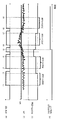
- FIG. 3 is a time chart illustrating the operation of the correction control of the target EGR rate described above.
- a steady determination state in order from the top, (a) a steady determination state, (b) the illustrated average effective pressure fluctuation rate cPi, (c) an EGR rate correction amount, and (d) a target EGR rate decrease experience flag are shown.
- A) The pulse waveform in the steady state determination state shows whether or not the engine rotation speed, the load, and the target EGR rate are in the steady state by combining the determination in step 1 and the determination in step 2 described above.
- the rising timing of the waveform of (a) is the timing of proceeding from step 3 to step 4 and subsequent steps in the flowchart of FIG.
- the illustrated average effective pressure volatility cPi is less than the predetermined threshold value, becomes equal to or more than the threshold value for a while from the time t5, and then becomes less than the threshold value again.
- the processes of steps 5, 6, 7, and 8 of FIG. 2 are repeatedly executed from the time t1, and the target is as shown in (c) at the time t2 in which the state continues for a predetermined number of cycles.
- the EGR rate is added and corrected by a predetermined amount. With this increase correction, the determination in step 3 in FIG. 2 becomes NO.
- the processes of steps 5, 6, 7, and 8 of FIG. 2 are repeatedly executed again at time t3, and as shown in (c), at time t4 in which the state continues for a predetermined number of cycles, as shown in (c).
- the target EGR rate is further increased and corrected by a predetermined amount.
- the target EGR rate gradually increases step by step every time the predetermined number of cycles elapses. Since there is a delay before the change in the target EGR rate is reflected in the illustrated average effective pressure fluctuation rate cPi, by performing the next increase correction after waiting for the lapse of a predetermined number of cycles, combustion deterioration due to a rapid increase in the EGR rate The EGR rate can be brought close to the limit while avoiding the above.
- the indicated average effective pressure fluctuation rate cPi eventually becomes equal to or higher than the threshold value.
- the illustrated average effective pressure volatility cPi becomes equal to or higher than the threshold value at time t5.
- the target EGR rate is immediately reduced and corrected by the processing flow of steps 5, 11, 12, 13, and 17 of FIG. 2 described above.
- the process of step 13 sets the target EGR rate reduction experience flag to 1.
- the target EGR rate decreases immediately without waiting for the lapse of the number of cycles. As a result, it is possible to prevent the combustion deterioration state from continuing for a long time.
- the process proceeds from step 3 to step 4 in FIG. 2 at the time t6 after a slight delay determined to be a transient state.
- the illustrated average effective pressure volatility cPi is equal to or higher than the threshold value, but at this time, since the target EGR rate decrease experience flag is 1, the process proceeds from step 11 to step 14. Therefore, the target EGR rate is not reduced and corrected at this time t6.
- the target EGR rate is reduced and corrected again at time t7.
- the reduction correction for the second and subsequent times is performed after waiting for the lapse of a predetermined number of cycles, so that the decrease in the target EGR rate is minimized.
- the effect of the cycle in which the EGR rate was still high before the time t5 can be eliminated.
- the combustion stability is improved by correcting the target EGR rate twice.
- the illustrated average effective pressure fluctuation rate cPi is less than the threshold value
- time t9 the illustrated average effective pressure fluctuation rate is shown.
- a predetermined number of cycles elapses when cPi is less than the threshold value.
- the target EGR rate decrease experience flag is 1, the increase correction of the target EGR rate is prohibited. That is, the target EGR rate is not corrected by completing the routine through step 6 in FIG. This is to prevent the combustion deterioration due to the increase in the EGR rate again because the combustion deterioration actually occurred due to the increase in the EGR rate at the same operating point (engine rotation speed and load).
- the target EGR rate reduction experience flag becomes 0 if the operating point changes. Therefore, as long as it stays at the same operating point, deterioration of combustion due to an unnecessary increase in EGR rate is avoided.
- the correction amount for the increase correction and the correction amount for the decrease correction of the EGR rate are shown to be equal for the sake of simplification of the figure, but the correction amounts are different. You may. Further, the correction amount at the time of the first reduction correction may be different from the correction amount at the time of the second and subsequent reduction corrections, and for example, it is possible to give a large amount of the first reduction correction.
- the predetermined number of cycles for the increase correction and the predetermined number of cycles for the decrease correction of the target EGR do not necessarily have to be the same number of cycles.
- the number of these cycles and the number of cycles used to calculate the moving average of the illustrated average effective pressure volatility cPi may be different values.
- the predetermined number of cycles for the increase correction and the number of cycles for the decrease correction are equal to each other, which is substantially the same as the number of cycles used for calculating the moving average of the illustrated average effective pressure volatility cPi. be equivalent to.
Landscapes
- Engineering & Computer Science (AREA)
- Chemical & Material Sciences (AREA)
- Combustion & Propulsion (AREA)
- Mechanical Engineering (AREA)
- General Engineering & Computer Science (AREA)
- Output Control And Ontrol Of Special Type Engine (AREA)
- Exhaust-Gas Circulating Devices (AREA)
- Combined Controls Of Internal Combustion Engines (AREA)
Priority Applications (5)
| Application Number | Priority Date | Filing Date | Title |
|---|---|---|---|
| JP2022528732A JP7485026B2 (ja) | 2020-06-04 | 2020-06-04 | 内燃機関の制御方法および制御装置 |
| PCT/IB2020/000548 WO2021245436A1 (ja) | 2020-06-04 | 2020-06-04 | 内燃機関の制御方法および制御装置 |
| EP20939429.5A EP4163485B1 (en) | 2020-06-04 | 2020-06-04 | Control method and control device for internal combustion engine |
| CN202080101391.XA CN115698490B (zh) | 2020-06-04 | 2020-06-04 | 内燃机的控制方法以及控制装置 |
| US18/007,735 US11808222B2 (en) | 2020-06-04 | 2020-06-04 | Control method and control device for internal combustion engine |
Applications Claiming Priority (1)
| Application Number | Priority Date | Filing Date | Title |
|---|---|---|---|
| PCT/IB2020/000548 WO2021245436A1 (ja) | 2020-06-04 | 2020-06-04 | 内燃機関の制御方法および制御装置 |
Publications (1)
| Publication Number | Publication Date |
|---|---|
| WO2021245436A1 true WO2021245436A1 (ja) | 2021-12-09 |
Family
ID=78831482
Family Applications (1)
| Application Number | Title | Priority Date | Filing Date |
|---|---|---|---|
| PCT/IB2020/000548 Ceased WO2021245436A1 (ja) | 2020-06-04 | 2020-06-04 | 内燃機関の制御方法および制御装置 |
Country Status (5)
| Country | Link |
|---|---|
| US (1) | US11808222B2 (https=) |
| EP (1) | EP4163485B1 (https=) |
| JP (1) | JP7485026B2 (https=) |
| CN (1) | CN115698490B (https=) |
| WO (1) | WO2021245436A1 (https=) |
Families Citing this family (1)
| Publication number | Priority date | Publication date | Assignee | Title |
|---|---|---|---|---|
| CN116517711B (zh) * | 2023-04-18 | 2025-09-09 | 重庆长安汽车股份有限公司 | 发动机控制方法、装置、单元及存储介质 |
Citations (5)
| Publication number | Priority date | Publication date | Assignee | Title |
|---|---|---|---|---|
| JPS60104754A (ja) | 1983-11-09 | 1985-06-10 | Toyota Motor Corp | 排気ガス再循環装置 |
| JPH0914028A (ja) | 1995-06-29 | 1997-01-14 | Nissan Motor Co Ltd | 内燃機関の安定度制御装置 |
| JP2002130028A (ja) * | 2000-10-27 | 2002-05-09 | Toyota Motor Corp | 内燃機関の燃焼制御装置 |
| JP2014177911A (ja) | 2013-03-15 | 2014-09-25 | Fuji Heavy Ind Ltd | エンジンの制御装置 |
| JP2019167009A (ja) * | 2018-03-23 | 2019-10-03 | トヨタ自動車株式会社 | ハイブリッド車両の制御装置 |
Family Cites Families (10)
| Publication number | Priority date | Publication date | Assignee | Title |
|---|---|---|---|---|
| JPS59128962A (ja) * | 1983-01-10 | 1984-07-25 | Nissan Motor Co Ltd | 内燃機関の排気還流制御装置 |
| JPH08246940A (ja) * | 1995-03-06 | 1996-09-24 | Nissan Motor Co Ltd | 内燃機関の燃焼状態制御装置 |
| JP3428611B2 (ja) * | 1996-05-28 | 2003-07-22 | 三菱自動車工業株式会社 | 内燃エンジンの燃焼変動制御装置 |
| JP3792506B2 (ja) * | 2000-12-01 | 2006-07-05 | 本田技研工業株式会社 | 内燃機関の制御装置 |
| JP2004183580A (ja) * | 2002-12-04 | 2004-07-02 | Mitsubishi Motors Corp | 内燃機関の排気浄化装置 |
| JP4440029B2 (ja) * | 2004-07-27 | 2010-03-24 | 三菱電機株式会社 | 内燃機関の制御装置 |
| EP2924264A4 (en) * | 2012-11-20 | 2016-01-20 | Toyota Motor Co Ltd | CONTROL DEVICE FOR A DIESEL ENGINE |
| JP6424067B2 (ja) * | 2014-11-06 | 2018-11-14 | 日立オートモティブシステムズ株式会社 | エンジン制御装置 |
| JP2016094909A (ja) * | 2014-11-14 | 2016-05-26 | トヨタ自動車株式会社 | 内燃機関の制御装置 |
| JP6920805B2 (ja) * | 2016-09-30 | 2021-08-18 | 日立Astemo株式会社 | 内燃機関制御装置 |
-
2020
- 2020-06-04 WO PCT/IB2020/000548 patent/WO2021245436A1/ja not_active Ceased
- 2020-06-04 EP EP20939429.5A patent/EP4163485B1/en active Active
- 2020-06-04 CN CN202080101391.XA patent/CN115698490B/zh active Active
- 2020-06-04 US US18/007,735 patent/US11808222B2/en active Active
- 2020-06-04 JP JP2022528732A patent/JP7485026B2/ja active Active
Patent Citations (5)
| Publication number | Priority date | Publication date | Assignee | Title |
|---|---|---|---|---|
| JPS60104754A (ja) | 1983-11-09 | 1985-06-10 | Toyota Motor Corp | 排気ガス再循環装置 |
| JPH0914028A (ja) | 1995-06-29 | 1997-01-14 | Nissan Motor Co Ltd | 内燃機関の安定度制御装置 |
| JP2002130028A (ja) * | 2000-10-27 | 2002-05-09 | Toyota Motor Corp | 内燃機関の燃焼制御装置 |
| JP2014177911A (ja) | 2013-03-15 | 2014-09-25 | Fuji Heavy Ind Ltd | エンジンの制御装置 |
| JP2019167009A (ja) * | 2018-03-23 | 2019-10-03 | トヨタ自動車株式会社 | ハイブリッド車両の制御装置 |
Non-Patent Citations (1)
| Title |
|---|
| See also references of EP4163485A4 |
Also Published As
| Publication number | Publication date |
|---|---|
| CN115698490B (zh) | 2026-03-17 |
| US11808222B2 (en) | 2023-11-07 |
| JP7485026B2 (ja) | 2024-05-16 |
| EP4163485B1 (en) | 2025-09-03 |
| CN115698490A (zh) | 2023-02-03 |
| EP4163485A1 (en) | 2023-04-12 |
| EP4163485A4 (en) | 2023-08-16 |
| JPWO2021245436A1 (https=) | 2021-12-09 |
| US20230235709A1 (en) | 2023-07-27 |
Similar Documents
| Publication | Publication Date | Title |
|---|---|---|
| JP4625111B2 (ja) | 内燃機関の燃料制御装置 | |
| JP4433051B2 (ja) | 内燃機関の制御装置 | |
| US9151233B2 (en) | Vehicle controller | |
| US20080046128A1 (en) | Control system for internal combustion engine | |
| US9863343B2 (en) | Method and device for operating an exhaust gas recirculation of a self-ignition internal combustion engine, in particular of a motor vehicle | |
| WO2006016423A1 (ja) | エンジンの制御装置および制御方法 | |
| CN110962855A (zh) | 一种增程式汽车发动机扭矩控制系统及其方法 | |
| JP2007051619A (ja) | 過給圧制御装置 | |
| JP7485026B2 (ja) | 内燃機関の制御方法および制御装置 | |
| JP4997272B2 (ja) | 内燃機関の燃料供給制御装置 | |
| US12215643B2 (en) | Control device for internal combustion engine | |
| JP2015081578A (ja) | 内燃機関の制御装置 | |
| JP7026217B2 (ja) | 制御装置および制御方法 | |
| US11939928B2 (en) | EGR control method and EGR controller | |
| WO2022249395A1 (ja) | 内燃機関の排気還流制御方法および制御装置 | |
| JP7421687B2 (ja) | 内燃機関制御装置及び内燃機関制御方法 | |
| JP4858237B2 (ja) | 内燃機関の制御装置 | |
| US11459942B2 (en) | Control device for internal combustion engine | |
| JP2012007541A (ja) | 内燃機関の制御装置 | |
| JP2008255933A (ja) | アシスト機構付き過給機を備える内燃機関の制御装置 | |
| JP2007132298A (ja) | 内燃機関の制御装置 | |
| JP6311363B2 (ja) | 内燃機関の制御装置 | |
| JP2015197096A (ja) | 内燃機関の制御装置 | |
| JP2012097599A (ja) | 内燃機関のegr制御装置 | |
| JP2008155813A (ja) | 車両の制御装置、制御方法およびその方法をコンピュータで実現されるプログラムならびにそのプログラムを記録した記録媒体 |
Legal Events
| Date | Code | Title | Description |
|---|---|---|---|
| 121 | Ep: the epo has been informed by wipo that ep was designated in this application |
Ref document number: 20939429 Country of ref document: EP Kind code of ref document: A1 |
|
| ENP | Entry into the national phase |
Ref document number: 2022528732 Country of ref document: JP Kind code of ref document: A |
|
| NENP | Non-entry into the national phase |
Ref country code: DE |
|
| ENP | Entry into the national phase |
Ref document number: 2020939429 Country of ref document: EP Effective date: 20230104 |
|
| WWG | Wipo information: grant in national office |
Ref document number: 2020939429 Country of ref document: EP |