WO2022249395A1 - 内燃機関の排気還流制御方法および制御装置 - Google Patents
内燃機関の排気還流制御方法および制御装置 Download PDFInfo
- Publication number
- WO2022249395A1 WO2022249395A1 PCT/JP2021/020185 JP2021020185W WO2022249395A1 WO 2022249395 A1 WO2022249395 A1 WO 2022249395A1 JP 2021020185 W JP2021020185 W JP 2021020185W WO 2022249395 A1 WO2022249395 A1 WO 2022249395A1
- Authority
- WO
- WIPO (PCT)
- Prior art keywords
- exhaust gas
- gas recirculation
- ignition timing
- internal combustion
- combustion engine
- Prior art date
Links
- 238000002485 combustion reaction Methods 0.000 title claims abstract description 59
- 238000000034 method Methods 0.000 title claims description 21
- 238000010992 reflux Methods 0.000 title 1
- 238000005070 sampling Methods 0.000 claims abstract description 24
- 238000001514 detection method Methods 0.000 claims description 7
- 230000000979 retarding effect Effects 0.000 claims description 4
- 230000001788 irregular Effects 0.000 claims 1
- 239000000446 fuel Substances 0.000 description 11
- 238000012545 processing Methods 0.000 description 7
- 238000002347 injection Methods 0.000 description 6
- 239000007924 injection Substances 0.000 description 6
- 238000011144 upstream manufacturing Methods 0.000 description 4
- 239000003054 catalyst Substances 0.000 description 3
- 230000000052 comparative effect Effects 0.000 description 3
- 230000003247 decreasing effect Effects 0.000 description 2
- 230000001687 destabilization Effects 0.000 description 2
- 238000010586 diagram Methods 0.000 description 2
- 238000011156 evaluation Methods 0.000 description 2
- 239000012041 precatalyst Substances 0.000 description 2
- 102100023226 Early growth response protein 1 Human genes 0.000 description 1
- 101001049697 Homo sapiens Early growth response protein 1 Proteins 0.000 description 1
- 238000012790 confirmation Methods 0.000 description 1
- 239000000498 cooling water Substances 0.000 description 1
- 230000001186 cumulative effect Effects 0.000 description 1
- 230000006866 deterioration Effects 0.000 description 1
- 238000002474 experimental method Methods 0.000 description 1
- 238000012986 modification Methods 0.000 description 1
- 230000004048 modification Effects 0.000 description 1
- 230000003134 recirculating effect Effects 0.000 description 1
- 238000004088 simulation Methods 0.000 description 1
- 239000002699 waste material Substances 0.000 description 1
- XLYOFNOQVPJJNP-UHFFFAOYSA-N water Substances O XLYOFNOQVPJJNP-UHFFFAOYSA-N 0.000 description 1
Images


Classifications
-
- F—MECHANICAL ENGINEERING; LIGHTING; HEATING; WEAPONS; BLASTING
- F02—COMBUSTION ENGINES; HOT-GAS OR COMBUSTION-PRODUCT ENGINE PLANTS
- F02D—CONTROLLING COMBUSTION ENGINES
- F02D21/00—Controlling engines characterised by their being supplied with non-airborne oxygen or other non-fuel gas
- F02D21/06—Controlling engines characterised by their being supplied with non-airborne oxygen or other non-fuel gas peculiar to engines having other non-fuel gas added to combustion air
- F02D21/08—Controlling engines characterised by their being supplied with non-airborne oxygen or other non-fuel gas peculiar to engines having other non-fuel gas added to combustion air the other gas being the exhaust gas of engine
-
- Y—GENERAL TAGGING OF NEW TECHNOLOGICAL DEVELOPMENTS; GENERAL TAGGING OF CROSS-SECTIONAL TECHNOLOGIES SPANNING OVER SEVERAL SECTIONS OF THE IPC; TECHNICAL SUBJECTS COVERED BY FORMER USPC CROSS-REFERENCE ART COLLECTIONS [XRACs] AND DIGESTS
- Y02—TECHNOLOGIES OR APPLICATIONS FOR MITIGATION OR ADAPTATION AGAINST CLIMATE CHANGE
- Y02T—CLIMATE CHANGE MITIGATION TECHNOLOGIES RELATED TO TRANSPORTATION
- Y02T10/00—Road transport of goods or passengers
- Y02T10/10—Internal combustion engine [ICE] based vehicles
- Y02T10/40—Engine management systems
Definitions
- the present invention relates to exhaust gas recirculation control for an internal combustion engine, and more particularly to exhaust gas recirculation control that determines an appropriate target exhaust gas recirculation rate based on detection of combustion fluctuations.
- Exhaust gas recirculation also abbreviated as EGR
- EGR rate exhaust gas recirculation rate
- Patent Document 1 an ion current is detected via a spark plug while increasing or decreasing the EGR rate, and when an ion current generated during an exhaust stroke due to destabilization of combustion is detected, the EGR rate is immediately before a misfire. is the limit exhaust gas recirculation rate.
- the ignition timing is set to a sampling ignition timing retarded from the basic ignition timing in order to determine the target exhaust gas recirculation rate.
- the target exhaust gas recirculation rate is determined.
- the limit target exhaust gas recirculation rate can be obtained without being affected by the misfire cycle.
- FIG. 1 is a configuration explanatory diagram showing the system configuration of an internal combustion engine to which the present invention is applied; Explanatory drawing which showed the operation
- FIG. 1 shows the system configuration of an automotive internal combustion engine 1 to which the present invention is applied.
- the internal combustion engine 1 is, for example, a four-stroke cycle spark ignition internal combustion engine equipped with a turbocharger 2.
- a pair of intake valves 4 and a pair of exhaust valves 5 are arranged on the ceiling wall surface of each cylinder 3.
- an ignition plug 6 is arranged in a central portion surrounded by these intake valves 4 and exhaust valves 5 .
- a fuel injection valve 7 for supplying fuel into the cylinder 3 is provided below the intake valve 4 .
- An engine controller 9 controls the ignition timing of the ignition plug 6 and the injection timing and injection amount of fuel by the fuel injection valve 7 .
- a washer-like in-cylinder pressure sensor 8 is provided on the seat where the spark plug 6 is attached to detect the in-cylinder pressure.
- an in-cylinder pressure sensor whose detection portion faces the combustion chamber 10 may be used.
- An intake passage 11 connected to the combustion chamber 10 via the intake valve 4 has an intake collector 11a.
- a controlled throttle valve 12 is provided.
- a compressor 2a of the turbocharger 2 is positioned upstream of the throttle valve 12, and an airflow meter 14 and an air cleaner 15 for detecting the amount of intake air are disposed upstream of the compressor 2a.
- a water-cooled intercooler 16 is provided between the compressor 2a and the throttle valve 12, for example.
- a recirculation valve 17 is provided to communicate the discharge side and the suction side of the compressor 2a. This recirculation valve 17 is opened during deceleration when the throttle valve 12 is closed.
- a turbine 2b of the turbocharger 2 is interposed in an exhaust passage 20 connected to the combustion chamber 10 via an exhaust valve 5, and a pre-catalyst device 21 and a main catalyst device each comprising a three-way catalyst are provided downstream thereof. 22 are provided.
- An air-fuel ratio sensor 23 that detects the air-fuel ratio is arranged upstream of the turbine 2b in the exhaust passage 20.
- the turbine 2b is equipped with a wastegate valve 24 that bypasses part of the exhaust depending on the boost pressure in order to control the boost pressure.
- the waste gate valve 24 is, for example, of an electric type whose opening is controlled by the engine controller 9 .
- an exhaust gas recirculation passage 25 for recirculating part of the exhaust gas from the exhaust passage 20 to the intake passage 11 is provided.
- one end of the exhaust gas recirculation passage 25 is connected between the pre-catalyst device 21 and the main catalyst device 22 of the exhaust passage 20, and the other end of the exhaust gas recirculation passage 25 is connected to a position upstream of the compressor 2a of the intake passage 11.
- the exhaust gas recirculation passage 25 includes, for example, a water-cooled EGR gas cooler 27 that cools the recirculated exhaust gas, and an EGR valve 28 that controls the exhaust gas recirculation amount. The opening of the EGR valve 28 is controlled by the engine controller 9 .
- the engine controller 9 includes the in-cylinder pressure sensor 8, the airflow meter 14, the air-fuel ratio sensor 23, a crank angle sensor 31 for detecting the engine rotation speed, a water temperature sensor 32 for detecting the cooling water temperature, An accelerator opening sensor 33 that detects the amount of depression of the accelerator pedal to be operated, a vehicle speed sensor 34 that directly or indirectly detects the vehicle speed, an atmospheric pressure sensor 35 that detects the atmospheric pressure, an outside temperature sensor 36 that detects the outside temperature, an excess Detection signals from sensors such as the supercharging pressure sensor 37 for detecting the boost pressure are input. Based on these detection signals, the engine controller 9 optimizes the fuel injection amount, injection timing, ignition timing, opening of the throttle valve 12, opening of the EGR valve 28 (in other words, EGR rate), boost pressure, etc. controlled to
- the engine controller 9 processes the detection signal of the in-cylinder pressure sensor 8 to calculate the indicated mean effective pressure fluctuation rate CPi (hereinafter simply referred to as the fluctuation rate CPi), which is an index indicating the combustion fluctuation. Then, as will be described later, at the beginning of exhaust gas recirculation, a target EGR rate set for each engine operating condition (load and rotational speed) is searched for or determined using the fluctuation rate CPi.
- the target EGR rate is the highest EGR rate within a range that does not cause excessive destabilization of combustion.
- the exhaust gas recirculation amount (the opening of the EGR valve 28) is controlled along with this target EGR rate.
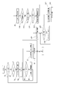
- FIG. 2 is an explanatory diagram for explaining the principle of the present invention, showing (a) EGR rate, (b) ignition timing, and (c) fluctuation rate CPi in comparison.
- the horizontal axis represents time, and shows changes in the fluctuation rate CPi when the EGR rate is increased stepwise as shown in column (a) in order to search for the target EGR rate, which is the limit of combustion stability. ing.
- dashed lines in columns (b) and (c) indicate a comparative example, in which the ignition timing is maintained at the basic ignition timing (eg MBT).
- the fluctuation rate CPi gradually increases as the EGR rate increases.
- this misfire MF occurs suddenly due to cycle variation or the like, it becomes a factor that makes evaluation of combustion fluctuation difficult.
- a misfire MF occurs before threshold CPi#2, which is the permissible limit of combustion fluctuation, is reached, and determination based on threshold CPi#2 becomes impossible.
- the sampling ignition timing retarded by a predetermined amount from the basic ignition timing is used for searching for the target EGR rate. Then, the EGR rate is gradually increased, and the EGR rate when the variation rate CPi reaches a predetermined threshold value CPi#, for example, is set as the limit EGR rate, that is, the target EGR rate.
- the retard amount of the sampling ignition timing may be set to, for example, about 5 to 15° CA, and an example is 10° CA. This retard amount may be a constant value regardless of the operating conditions, or it may be set according to the rotation speed so that the higher the rotation speed, the smaller the value, taking into consideration changes in real time. can be
- the fluctuation rate CPi increases as a whole, but misfires are less likely to occur, and the fluctuation rate CPi increases as the EGR rate increases. can be grasped without being affected by misfire. Therefore, for example, by appropriately setting the threshold value CPi# of the variation rate CPi under the sampling ignition timing, the variation rate CPi will reach the threshold value CPi#2 under the basic ignition timing. can be searched for.
- the EGR rate shown as EGR1 in column (a) is the target EGR rate.
- the thresholds CPi#2 and CPi# differ depending on the level to which they are permissible.
- the threshold CPi#2 is about 2%, and the threshold CPi# is about 5%, for example. is.
- the threshold CPi# is set in consideration of the retard amount of the sampling ignition timing.
- the amount of change in CPi with respect to the amount of change in the EGR rate (for example, the unit change amount shown in steps in column a) is greater when the ignition timing is on the retard side than when the ignition timing is at the MBT point. It becomes larger at the sampling ignition timing, and in particular at an EGR rate close to the limit EGR rate, the amount of change in the variation rate CPi under the sampling ignition timing becomes remarkably large. Therefore, it is possible to determine that the limit EGR rate is reached when the rate of increase of variation rate CPi when the EGR rate is gradually increased reaches a predetermined magnitude, instead of comparison with threshold value CPi#.
- FIG. 3 is a flow chart showing the flow of processing executed by the engine controller 9, and the routine shown in this flow chart is repeatedly executed, for example, at regular time intervals.
- step 1 it is determined whether or not the operating condition or operating point defined by the load and rotational speed is within a predetermined EGR region in which exhaust gas recirculation should be performed. If it is outside the EGR region, the routine ends. If it is within the EGR region, the process proceeds to step 2, and it is determined whether learning (that is, search or determination) of the target EGR rate has not yet been performed for the operating condition. Since the learning is not performed the first time, the process advances from step 2 to step 3 to set the ignition timing to the sampling ignition timing retarded by a predetermined amount (for example, 10° CA) from the basic ignition timing (MBT in one embodiment).
- a predetermined amount for example, 10° CA
- step 5 the fluctuation rate CPi is compared with a predetermined threshold value (corresponding to the aforementioned threshold value CPi#), and in step 6, the EGR rate at that time is gradually increased by adding a constant amount ⁇ .
- a predetermined threshold value corresponding to the aforementioned threshold value CPi#
- step 6 the EGR rate at that time is gradually increased by adding a constant amount ⁇ .
- the variation rate CPi gradually increases without misfiring and eventually reaches the threshold value. If it is determined in step 5 that the variation rate CPi is equal to or greater than the threshold value, the process proceeds to step 7, and the EGR rate at that time is learned as the target EGR rate.
- step 8 the process proceeds to step 8 to end retarding the ignition timing for searching for the target EGR rate.
- step 8 instead of the comparison with the threshold value in step 5, it is also possible to make a determination based on the rate of increase of the fluctuation rate CPi.
- step 9 exhaust gas recirculation is controlled according to the learned target EGR rate.
- the search or determination of the target EGR rate and the exhaust gas recirculation control using the learned target EGR rate are performed for each engine operating condition (operating point).
- each learned target EGR rate is assigned to a map having load and rotational speed as parameters. Therefore, when the operating condition changes to an unlearned operating condition, the operating condition is newly learned.
- the target EGR rate which is a learned value on the map, is initialized at the start of a vehicle trip.
- step 10 it is determined whether or not it is time to reconfirm the adequacy of the learned value (target EGR rate).
- target EGR rate the cumulative operating time under the same operating conditions reaches a certain time (eg, 5 minutes, etc.). or (3) a misfire is detected, it is determined that reconfirmation of the target EGR rate is necessary.
- the above condition (1) is for reconfirming whether the target EGR rate set in steps 5-7 is appropriate.
- the above condition (2) takes into consideration the fact that the EGR rate, which actually becomes the limit of combustion stability, may change during continuous operation.
- the above condition (3) is for relearning immediately when a misfire occurs under the target EGR rate.
- step 10 in steps 11 to 13, while exhaust gas recirculation is performed in accordance with the target EGR rate, the variation rate CPi is determined to be equal to or greater than the above threshold under ignition timing with a smaller retard amount than the sampling ignition timing. determine whether or not That is, in step 11, the retard amount is compared with a predetermined retard amount (for example, 10° CA) which is the retard amount of the sampling ignition timing. If it is less than the predetermined retard amount, it is determined in step 12 whether the fluctuation rate CPi is less than the threshold value. If YES in step 12, the process proceeds to step 13 to increment the retard amount by a constant amount ⁇ .
- a predetermined retard amount for example, 10° CA
- the fluctuation rate CPi basically increases according to the retard amount.
- the variation rate CPi becomes equal to or higher than the threshold value before the retard amount reaches the predetermined retard amount when the retard amount is increased, the process proceeds from step 12 to step 14 .
- the learned target EGR rate is excessive, and re-learning is performed in steps 14 to 18 in the direction of lowering the target EGR rate. That is, at step 14, the retard amount is again set to the sampling ignition timing, and at step 15, it is determined whether or not the fluctuation rate CPi is less than the threshold value, and at step 16, the EGR rate is decremented by a constant amount ⁇ .
- step 15 the EGR rate is searched for when the fluctuation rate CPi is below the threshold.
- step 15 the process proceeds from step 15 to step 17, the EGR rate at that time is set as the target EGR rate (that is, learned), and in step 18 the ignition timing is returned to the basic ignition timing (eg MBT).
- the processing may be returned from step 14 to step 4 for re-learning.
- step 11 is executed.
- re-learning is performed under a predetermined retard amount, ie, sampling ignition timing.
- the target EGR rate which is the current learned value, is at least not excessively high, but may be too small.
- a search for an appropriate target EGR rate is performed again under the sampling ignition timing. Therefore, in this embodiment, if the operation is continued under the same operating conditions, the target EGR rate is learned and updated at least every fixed time (for example, 5 minutes). It should be noted that the confirmation process from step 11 onward may be performed not necessarily at regular intervals but at appropriate timings.
- the ignition timing may be retarded for searching for the target EGR rate only in some cylinders, for example, only one specific cylinder, and the variation rate CPi may be calculated for that cylinder.
- the other cylinders continue to operate at the basic ignition timing (MBT, for example) during learning and re-learning, thereby minimizing deterioration in fuel consumption caused by retarding the ignition timing.
- the retard amount of the sampling ignition timing may be set according to the rotation speed so that the higher the rotation speed, the smaller the value.
- CPi is affected by the retard amount. Therefore, the optimal retard amount and the threshold value of the fluctuation rate CPi under each operating condition are determined in advance by experiments or simulations, and these retard amount and threshold values are mapped on a map with load and rotational speed as parameters. You can leave it as is.
- the present invention is not limited to the above embodiment, and various modifications are possible.
- the indicated mean effective pressure fluctuation rate CPi based on the detection signal of the in-cylinder pressure sensor 8 is used as an index indicating combustion fluctuation, but the index indicating combustion fluctuation is not limited to the indicated mean effective pressure fluctuation rate CPi. , may be any other suitable index.
- an appropriate index indicating combustion fluctuation may be obtained from changes in the rotation speed of the crankshaft.
Abstract
内燃機関(1)の運転条件(負荷および回転速度)がEGR領域内となったときに、燃焼変動の限界となる目標EGR率の探索・決定を行う。点火時期を基本点火時期(例えばMBT)から例えば10°CAリタードしたサンプリング用点火時期とし、EGR率を徐々に高めていき、燃焼変動を示す変動率CPiが閾値CPi♯に達したときのEGR率を目標EGR率とする。点火時期リタードにより変動率CPiは全体として高くなるが、失火(MF)が生じにくくなるので、突発的に発生する失火に影響されずに限界となるEGR率を確実に探索することができる。
Description
この発明は、内燃機関の排気還流制御、特に燃焼変動の検出に基づいて適切な目標排気還流率を決定する排気還流制御に関する。
排気の一部を吸気系に還流する排気還流(EGRとも略称される)は、燃費の向上に寄与するが、過大な排気還流は燃焼を不安定とし、失火を生じる。そのため、排気還流を行いつつ燃焼安定性を検知することで、過度の燃焼不安定化を招来しない範囲で最も高い排気還流率(EGR率)つまり限界排気還流率を探索することが知られている。
特許文献1には、EGR率を増減変化させながら点火プラグを介してイオン電流の検出を行い、燃焼不安定化に起因する排気行程中のイオン電流の発生を検出したときのEGR率が失火直前の限界排気還流率である、とする技術が開示されている。
燃費を最良とするために点火時期をMBT点もしくはMBT点付近とした一般的な内燃機関の運転においては、例えばEGR率を徐々に高くしていったときに、EGR率の変化に対する燃焼安定度の変化は比較的に小さく、なおかつ、ある段階でサイクルばらつきをも含めて突発的に失火が生じる。このような特性から、限界排気還流率の探索は一般に困難である。例えば図示平均有効圧変動率CPi等の燃焼変動を示す指標を用いてEGR率に対する燃焼安定度の関係を評価しようとした場合に、失火サイクルの影響を受けて適切な評価を行うことができない。
これは、特許文献1の技術においても同様であり、EGR率を増減変化させている間の突発的な失火サイクルの発生により限界排気還流率の探索が影響されてしまう。
この発明は、目標排気還流率の決定のために点火時期を基本点火時期よりもリタードしたサンプリング用点火時期に設定し、このサンプリング用点火時期の下での排気還流率と燃焼変動との関係から上記目標排気還流率を決定する。
点火時期をリタードすることで、燃焼変動は全体として僅かに悪化するが、失火は生じにくくなり、基本点火時期の下で限界排気還流率付近となるEGR率においても、失火を生じずにEGR率に応じて燃焼変動が変化する特性が得られる。
従って、失火サイクルに影響されずに限界となる目標排気還流率を求めることができる。
以下、この発明の一実施例を図面に基づいて詳細に説明する。
図1は、この発明が適用される自動車用内燃機関1のシステム構成を示している。この内燃機関1は、例えばターボチャージャ2を備えた4ストロークサイクルの火花点火式内燃機関であって、各シリンダ3の天井壁面に、一対の吸気弁4および一対の排気弁5が配置されているとともに、これらの吸気弁4および排気弁5に囲まれた中央部に点火プラグ6が配置されている。吸気弁4の下方には、シリンダ3内へ燃料を供給する燃料噴射弁7が設けられている。点火プラグ6の点火時期および燃料噴射弁7による燃料の噴射時期ならびに噴射量はエンジンコントローラ9によって制御される。
点火プラグ6が取り付けられる座部には、筒内圧を検出するために座金状の筒内圧センサ8が設けられている。なお、点火プラグ6とは別に、検出部が燃焼室10に臨んだ形式の筒内圧センサを用いるようにしてもよい。
吸気弁4を介して燃焼室10に接続される吸気通路11は、吸気コレクタ11aを有し、この吸気コレクタ11aよりも上流側に、エンジンコントローラ9からの制御信号によって開度が制御される電子制御型スロットルバルブ12が設けられている。スロットルバルブ12の上流側に、ターボチャージャ2のコンプレッサ2aが位置し、このコンプレッサ2aよりも上流に、吸入空気量を検出するエアフロメータ14およびエアクリーナ15が配設されている。コンプレッサ2aとスロットルバルブ12との間には、例えば水冷式のインタークーラ16が設けられている。また、コンプレッサ2aの吐出側と吸入側とを連通するようにリサーキュレーションバルブ17が設けられている。このリサーキュレーションバルブ17は、スロットルバルブ12が閉じる減速時に開弁される。
排気弁5を介して燃焼室10に接続される排気通路20には、ターボチャージャ2のタービン2bが介装されており、その下流側にそれぞれ三元触媒からなるプリ触媒装置21およびメイン触媒装置22が配設されている。排気通路20のタービン2bよりも上流側に、空燃比を検出する空燃比センサ23が配置されている。タービン2bは、過給圧を制御するために過給圧に応じて排気の一部をバイパスするウェストゲートバルブ24を備えている。ウェストゲートバルブ24は、例えば、エンジンコントローラ9によって開度が制御される電動型の構成のものが用いられている。
排気還流装置として、排気通路20から吸気通路11へ排気の一部を還流する排気還流通路25が設けられている。例えば、排気通路20のプリ触媒装置21とメイン触媒装置22との間に排気還流通路25の一端が接続され、吸気通路11のコンプレッサ2a上流側の位置に排気還流通路25の他端が接続されている。この排気還流通路25は、還流排気を冷却する例えば水冷式のEGRガスクーラ27と、排気還流量を制御するEGRバルブ28と、を備えている。EGRバルブ28の開度は、エンジンコントローラ9によって制御される。
上記エンジンコントローラ9には、上記の筒内圧センサ8、エアフロメータ14、空燃比センサ23のほか、機関回転速度を検出するためのクランク角センサ31、冷却水温を検出する水温センサ32、運転者により操作されるアクセルペダルの踏込量を検出するアクセル開度センサ33、車速を直接ないし間接に検出する車速センサ34、大気圧を検出する大気圧センサ35、外気温を検出する外気温センサ36、過給圧を検出する過給圧センサ37、等のセンサ類の検出信号が入力されている。エンジンコントローラ9は、これらの検出信号に基づき、燃料噴射量および噴射時期、点火時期、スロットルバルブ12の開度、EGRバルブ28の開度(換言すればEGR率)、過給圧、等を最適に制御している。
また、エンジンコントローラ9は、筒内圧センサ8の検出信号を処理することで、燃焼変動を示す指標となる図示平均有効圧変動率CPi(以下、単に変動率CPiと記す)を算出する。そして、後述するように、排気還流の開始初期に、機関運転条件(負荷および回転速度)毎に設定される目標EGR率の探索ないし決定を変動率CPiを用いて行う。目標EGR率は、過度の燃焼不安定化を招来しない範囲で最も高いEGR率であり、ある運転条件に対して排気還流の開始初期に目標EGR率を決定した後は、当該運転条件の下ではこの目標EGR率に沿って排気還流量(EGRバルブ28の開度)が制御されることとなる。
次に、本発明の要部である排気還流の制御、特に目標EGR率の探索ないし決定について説明する。
図2は、本発明の原理を説明するための説明図であり、(a)EGR率と(b)点火時期と(c)変動率CPiとを対比して示している。横軸は時間であり、燃焼安定度の限界となる目標EGR率の探索のために(a)欄に示すようにEGR率をステップ的に増加させていったときの変動率CPiの変化を示している。
ここで(b),(c)欄における破線は比較例を示しており、この比較例では、点火時期は基本点火時期(例えばMBT)に保たれている。比較例では、EGR率が徐々に増加していくと、変動率CPiはEGR率増加に伴って徐々に大きくなっていくが、ある段階で突発的に失火((c)欄に符号MFとして示す)が発生する。この失火MFはサイクルばらつき等によって突発的に生じるので、燃焼変動の評価を困難にする要因となる。例えば図示例では、燃焼変動の許容限界となる閾値CPi♯2に達する前に失火MFが生じてしまい、閾値CPi♯2による判定が不能となる。
これに対し、本発明の実施例では、目標EGR率の探索のために点火時期を基本点火時期(例えばMBT)から所定量リタードしたサンプリング用点火時期とする。そして、EGR率を徐々に増加させていき、例えば変動率CPiが所定の閾値CPi♯に達したときのEGR率を限界のEGR率つまり目標EGR率とするのである。サンプリング用点火時期のリタード量としては、例えば、5~15°CA程度に設定すればよく、一例では10°CAである。このリタード量は、運転条件によらずに一定値であってもよく、あるいは、実時間の変化を考慮して、回転速度が高いほど小さな値となるように、回転速度に応じて設定するようにしてもよい。
このように点火時期をMBT点よりもリタードすると、(c)欄に示すように、変動率CPiは全体として増加するが、失火は生じにくくなり、EGR率の増加に伴って増大する変動率CPiの傾向を失火に影響されずに把握することができる。そのため、例えば、サンプリング用点火時期の下での変動率CPiの閾値CPi♯を適切に設定することにより、基本点火時期の下で変動率CPiが閾値CPi♯2に達することとなるであろう限界のEGR率を探索することができる。例えば図示例では、(a)欄にEGR1として示すEGR率が目標EGR率となる。閾値CPi♯2,CPi♯は、どのレベルまで許容し得るか等によって異なるが、一例を挙げると、閾値CPi♯2は2%程度であり、これに対応して閾値CPi♯は例えば5%程度である。なお、点火時期をリタードしたときに、基本的に、そのリタード量が大きいほど変動率CPiが高くなる。従って、閾値CPi♯は、サンプリング用点火時期のリタード量を考慮して設定される。
また、C欄に示すように、EGR率の変化量(例えばa欄にステップ状に示す単位変化量)に対するCPiの変化量は、点火時期がMBT点である場合よりも点火時期がリタード側のサンプリング用点火時期である場合の方が大となり、特に、限界EGR率に近いEGR率においては、サンプリング用点火時期の下での変動率CPiの変化量が顕著に大きくなる。従って、閾値CPi♯との比較ではなく、EGR率を徐々に増加していったときの変動率CPiの増加率が所定の大きさとなったときに限界EGR率であると判定することもできる。
なお、(c)欄の変動率CPiの変化は、理解を容易にするために模式的に描いたものであり、実際の波形を厳密に表したものではない。
次に一実施例の処理の流れを図3のフローチャートに従って説明する。図3は、エンジンコントローラ9において実行される処理の流れを示すフローチャートであり、このフローチャートに示すルーチンは、例えば一定時間毎に繰り返し実行される。ステップ1では、負荷および回転速度によって規定される運転条件ないし運転点が排気還流を行うべき所定のEGR領域にあるかどうかを判定する。EGR領域外であれば、ルーチンを終了する。EGR領域内であればステップ2へ進み、当該運転条件について目標EGR率の学習(つまり探索ないし決定)がまだ行われていないかどうか判定する。初回は未学習であるので、ステップ2からステップ3へ進み、点火時期を基本点火時期(一実施例ではMBT)から所定量(例えば10°CA)リタードしたサンプリング用点火時期に設定する。
ステップ4でEGR率を0に初期化した後、ステップ5,6の処理を繰り返し、限界となる目標EGR率を探索する。すなわち、ステップ5では変動率CPiを所定の閾値(前述の閾値CPi♯に相当する)と比較し、ステップ6では、そのときのEGR率に一定量αを加えて徐々に増加させる。前述したように、点火時期をサンプリング用点火時期までリタードした状態でEGR率を徐々に増加することによって、失火を伴わずに変動率CPiが徐々に増加し、やがて閾値に達する。ステップ5において変動率CPiが閾値以上であると判定したら、ステップ7へ進み、そのときのEGR率を目標EGR率として学習する。そして、ステップ8へ進み、目標EGR率の探索のための点火時期のリタードを終了する。なお、前述したように、ステップ5における閾値との比較に代えて、変動率CPiの増加率に基づく判定を行うことも可能である。
以後は、ステップ2からステップ9へ進み、学習した目標EGR率に沿って排気還流が制御される。なお、目標EGR率の探索ないし決定および学習した目標EGR率を用いた排気還流制御は、機関運転条件(運転点)毎に行われる。例えば、負荷と回転速度とをパラメータとしたマップにそれぞれ学習した目標EGR率が割り付けられることとなる。従って、運転条件が未学習の運転条件へと変化したら、当該運転条件について新たに学習がなされる。また、好ましい一実施例では、車両のトリップの開始時にマップ上の学習値である目標EGR率が初期化される。
ステップ9に続くステップ10は、学習値(目標EGR率)の適否を再確認すべきタイミングであるかどうかを判定する。一実施例では、(1)目標EGR率を学習した直後(つまり初回にステップ10に進んだとき)、(2)同じ運転条件の積算運転時間が一定時間(例えば5分、等)に達した、あるいは、(3)失火を検出した、のいずれかによって目標EGR率の再確認が必要であると判定される。上記の(1)の条件は、ステップ5~7で設定した目標EGR率が適切であるかどうかを再確認するためである。上記の(2)の条件は、運転を継続する中で実際に燃焼安定度の限界となるEGR率が変化することがあることを考慮したものである。上記の(3)の条件は、目標EGR率の下で失火が生じた場合に直ちに再学習を行うためのものである。
ステップ10でYESの場合は、ステップ11~13において、目標EGR率に沿った排気還流を行いながら、サンプリング用点火時期よりもリタード量が小さな点火時期の下で変動率CPiが上記の閾値以上となるかどうかの判定を行う。すなわち、ステップ11ではリタード量をサンプリング用点火時期のリタード量である所定リタード量(例えば10°CA)と比較する。所定リタード量未満であれば、ステップ12で変動率CPiが閾値未満であるか判定する。ステップ12でYESであれば、ステップ13へ進んでリタード量を一定量βずつインクリメントする。
前述したように、点火時期をリタードすると、変動率CPiは基本的にリタード量に応じて増加する。リタード量を増加させていったときにリタード量が所定リタード量に達する前に変動率CPiが閾値以上となった場合は、ステップ12からステップ14へと進むこととなる。これは学習した目標EGR率が過大であることを意味し、ステップ14~18において、目標EGR率を低下させる方向に再学習を行う。すなわち、ステップ14でリタード量を再びサンプリング用点火時期に設定し、ステップ15において変動率CPiが閾値未満であるかどうかの判定を行うとともに、ステップ16においてEGR率を一定量γずつデクリメントする。ステップ15,16を繰り返すことで、変動率CPiが閾値を下回るときのEGR率が探索される。ステップ15でYESとなったときにステップ15からステップ17へ進み、そのときのEGR率を目標EGR率として設定(つまり学習)し、ステップ18において点火時期を基本点火時期(例えばMBT)に戻す。
なお、ステップ15~18の処理に代えて、ステップ14から再学習のためにステップ4へ処理を戻すようにしてもよい。
一方、リタード量を徐々にインクリメントしていく上述したステップ11~13の処理を繰り返す中で、変動率CPiが閾値以上以上となる前にリタード量が所定リタード量に達した場合は、ステップ11からステップ5へ進み、所定量リタード量つまりサンプリング用点火時期の下で再学習を行う。これは、現在の学習値である目標EGR率が少なくとも過大ではないものの、逆に過小である可能性があることを考慮したものである。ステップ5,6の処理により、再度、サンプリング用点火時期の下で適切な目標EGR率の探索が行われる。従って、この実施例では、仮に同じ運転条件で運転を継続したときに、少なくとも一定時間(例えば5分、等)毎に目標EGR率の学習・更新が行われることとなる。なお、必ずしも一定間隔ではなく適当なタイミングにステップ11以降の確認処理を行うようにしてもよい。
また多気筒内燃機関の場合、一部の気筒例えば特定の1気筒のみにおいて目標EGR率の探索のための点火時期リタードを行い、当該気筒について変動率CPiの算出を行うようにしてもよい。このようにすれば、学習ならびに再学習の際に他の気筒は基本点火時期(例えばMBT)での運転が継続されるので、点火時期リタードに伴う燃費悪化が最小限となる。
上述したように、サンプリング用点火時期のリタード量は、回転速度が高いほど小さな値となるように、回転速度に応じて設定するようにしてもよく、またサンプリング用点火時期の下での変動率CPiはリタード量の影響を受ける。従って、各運転条件の下での最適なリタード量および変動率CPiの閾値を実験ないしシミュレーション等によって予め求めておき、負荷と回転速度とをパラメータとしたマップに、これらのリタード量および閾値をマッピングしておくようにしてもよい。
以上、この発明の一実施例を詳細に説明したが、この発明は上記実施例に限定されるものではなく、種々の変更が可能である。例えば上記実施例では燃焼変動を示す指標として筒内圧センサ8の検出信号に基づく図示平均有効圧変動率CPiを用いているが、燃焼変動を示す指標としては図示平均有効圧変動率CPiに限らず、適当な他の指標であってもよい。また、クランクシャフトの回転速度の変化から燃焼変動を示す適当な指標を求めるようにしてもよい。
Claims (9)
- 排気還流を行っている下で燃焼変動を検出し、この燃焼変動に基づき内燃機関の負荷と回転速度とに対応した目標排気還流率を決定する内燃機関の排気還流制御方法において、
目標排気還流率の決定のために点火時期を基本点火時期よりもリタードしたサンプリング用点火時期に設定し、
このサンプリング用点火時期の下での排気還流率と燃焼変動との関係から上記目標排気還流率を決定する、
内燃機関の排気還流制御方法。 - 内燃機関の運転開始後、内燃機関の運転条件が排気還流領域に入ったときに、サンプリング用点火時期にリタードして目標排気還流率の決定を行う、
請求項1に記載の内燃機関の排気還流制御方法。 - 排気還流率を徐々に増加していき、燃焼変動を示す指標が所定の閾値に達したときの排気還流率を目標排気還流率とする、
請求項1または2に記載の内燃機関の排気還流制御方法。 - 排気還流率を徐々に増加していき、燃焼変動を示す指標の増加率が所定の大きさに達したときの排気還流率を目標排気還流率とする、
請求項1または2に記載の内燃機関の排気還流制御方法。 - 上記基本点火時期からサンプリング用点火時期までのリタード量が、回転速度が高いほど小さくなるように、回転速度に応じて設定される、
請求項1~4のいずれかに記載の内燃機関の排気還流制御方法。 - 上記閾値と、上記基本点火時期からサンプリング用点火時期までのリタード量と、が、負荷と回転速度とに対応して予め設定されている、
請求項3に記載の内燃機関の排気還流制御方法。 - 複数気筒の中の一部気筒の点火時期をサンプリング用点火時期にリタードし、
当該気筒の燃焼変動を検出するとともに、この燃焼変動から目標排気還流率を決定する、
請求項1~6のいずれかに記載の内燃機関の排気還流制御方法。 - 目標排気還流率に従った内燃機関の運転中、定期的もしくは不定期的な間隔で、目標排気還流率に沿った排気還流を行いつつ点火時期をリタードし、リタードした点火時期の下での燃焼変動に基づき目標排気還流率が適切であることを確認する、
請求項1~7のいずれかに記載の内燃機関の排気還流制御方法。 - 排気還流装置と、
燃焼変動を直接にもしくは間接に検出するための燃焼変動検出デバイスと、
内燃機関の負荷と回転速度とに対応した目標排気還流率に沿って上記排気還流装置を制御するとともに、上記目標標排気還流率の決定の際に点火時期を基本点火時期よりもリタードしたサンプリング用点火時期に設定し、このサンプリング用点火時期の下での排気還流率と燃焼変動との関係から上記目標排気還流率を決定するコントローラと、
を備えた内燃機関の排気還流制御装置。
Priority Applications (2)
| Application Number | Priority Date | Filing Date | Title |
|---|---|---|---|
| PCT/JP2021/020185 WO2022249395A1 (ja) | 2021-05-27 | 2021-05-27 | 内燃機関の排気還流制御方法および制御装置 |
| JP2023523863A JPWO2022249395A1 (ja) | 2021-05-27 | 2021-05-27 |
Applications Claiming Priority (1)
| Application Number | Priority Date | Filing Date | Title |
|---|---|---|---|
| PCT/JP2021/020185 WO2022249395A1 (ja) | 2021-05-27 | 2021-05-27 | 内燃機関の排気還流制御方法および制御装置 |
Publications (1)
| Publication Number | Publication Date |
|---|---|
| WO2022249395A1 true WO2022249395A1 (ja) | 2022-12-01 |
Family
ID=84229613
Family Applications (1)
| Application Number | Title | Priority Date | Filing Date |
|---|---|---|---|
| PCT/JP2021/020185 WO2022249395A1 (ja) | 2021-05-27 | 2021-05-27 | 内燃機関の排気還流制御方法および制御装置 |
Country Status (2)
| Country | Link |
|---|---|
| JP (1) | JPWO2022249395A1 (ja) |
| WO (1) | WO2022249395A1 (ja) |
Citations (6)
| Publication number | Priority date | Publication date | Assignee | Title |
|---|---|---|---|---|
| WO1997033082A1 (fr) * | 1996-03-08 | 1997-09-12 | Mitsubishi Jidosha Kogyo Kabushiki Kaisha | Dispositif de commande d'un moteur a combustion interne de type a injection de carburant dans les cylindres |
| JP2007186998A (ja) * | 2005-12-14 | 2007-07-26 | Nissan Motor Co Ltd | エンジンの制御方法及び制御装置 |
| JP2014141943A (ja) * | 2013-01-24 | 2014-08-07 | Nissan Motor Co Ltd | ノッキング抑制装置及びノッキング抑制方法 |
| JP2016089733A (ja) * | 2014-11-06 | 2016-05-23 | 日立オートモティブシステムズ株式会社 | エンジン制御装置 |
| JP2019116871A (ja) * | 2017-12-27 | 2019-07-18 | トヨタ自動車株式会社 | 内燃機関の制御装置 |
| JP2019116872A (ja) * | 2017-12-27 | 2019-07-18 | トヨタ自動車株式会社 | 内燃機関の制御装置 |
-
2021
- 2021-05-27 JP JP2023523863A patent/JPWO2022249395A1/ja active Pending
- 2021-05-27 WO PCT/JP2021/020185 patent/WO2022249395A1/ja unknown
Patent Citations (6)
| Publication number | Priority date | Publication date | Assignee | Title |
|---|---|---|---|---|
| WO1997033082A1 (fr) * | 1996-03-08 | 1997-09-12 | Mitsubishi Jidosha Kogyo Kabushiki Kaisha | Dispositif de commande d'un moteur a combustion interne de type a injection de carburant dans les cylindres |
| JP2007186998A (ja) * | 2005-12-14 | 2007-07-26 | Nissan Motor Co Ltd | エンジンの制御方法及び制御装置 |
| JP2014141943A (ja) * | 2013-01-24 | 2014-08-07 | Nissan Motor Co Ltd | ノッキング抑制装置及びノッキング抑制方法 |
| JP2016089733A (ja) * | 2014-11-06 | 2016-05-23 | 日立オートモティブシステムズ株式会社 | エンジン制御装置 |
| JP2019116871A (ja) * | 2017-12-27 | 2019-07-18 | トヨタ自動車株式会社 | 内燃機関の制御装置 |
| JP2019116872A (ja) * | 2017-12-27 | 2019-07-18 | トヨタ自動車株式会社 | 内燃機関の制御装置 |
Also Published As
| Publication number | Publication date |
|---|---|
| JPWO2022249395A1 (ja) | 2022-12-01 |
Similar Documents
| Publication | Publication Date | Title |
|---|---|---|
| JP5103459B2 (ja) | エンジンの制御装置 | |
| US10288031B2 (en) | Controller for internal combustion engine | |
| US9127614B2 (en) | Torque-calculating control system for an internal combustion engine | |
| US7870844B2 (en) | Control system and method for internal combustion engine | |
| US9284897B2 (en) | Intake control system for internal combustion engine | |
| US20070235009A1 (en) | Control apparatus for direct injection type spark ignition internal combustion engine | |
| CN113015848B (zh) | 控制装置 | |
| JP6860313B2 (ja) | エンジンの制御方法、及び、エンジン | |
| JP6462311B2 (ja) | エンジンの制御装置 | |
| JP2011241727A (ja) | 内燃機関の異常検出装置および内燃機関の制御装置 | |
| WO2018179801A1 (ja) | 内燃機関の制御装置 | |
| JP5925641B2 (ja) | 内燃機関の吸気制御装置 | |
| WO2022249395A1 (ja) | 内燃機関の排気還流制御方法および制御装置 | |
| JP4859731B2 (ja) | 内燃機関の制御装置 | |
| JPH10159637A (ja) | 内燃機関の燃料噴射制御装置及び燃料噴射制御方法 | |
| WO2016190092A1 (ja) | エンジン制御装置 | |
| JP2011157852A (ja) | 内燃機関の制御装置 | |
| JP4277623B2 (ja) | 可変圧縮比機構付き内燃機関の点火時期制御装置 | |
| JP2019120204A (ja) | エンジン制御装置 | |
| JP4123340B2 (ja) | エンジンの吸気量算出装置 | |
| JP3879491B2 (ja) | 内燃機関の制御装置 | |
| CN113027617A (zh) | 发动机扫气控制装置、系统、方法及计算机可读取介质 | |
| JP6272003B2 (ja) | エンジンの制御装置 | |
| JPH0641151Y2 (ja) | ノッキングの検出装置 | |
| US11920549B2 (en) | Engine control method and engine control device |
Legal Events
| Date | Code | Title | Description |
|---|---|---|---|
| 121 | Ep: the epo has been informed by wipo that ep was designated in this application |
Ref document number: 21942146 Country of ref document: EP Kind code of ref document: A1 |
|
| ENP | Entry into the national phase |
Ref document number: 2023523863 Country of ref document: JP Kind code of ref document: A |
|
| NENP | Non-entry into the national phase |
Ref country code: DE |