WO2021240887A1 - Bandoulière et sac - Google Patents
Bandoulière et sac Download PDFInfo
- Publication number
- WO2021240887A1 WO2021240887A1 PCT/JP2021/003673 JP2021003673W WO2021240887A1 WO 2021240887 A1 WO2021240887 A1 WO 2021240887A1 JP 2021003673 W JP2021003673 W JP 2021003673W WO 2021240887 A1 WO2021240887 A1 WO 2021240887A1
- Authority
- WO
- WIPO (PCT)
- Prior art keywords
- shoulder belt
- shoulder
- region
- longitudinal direction
- bag
- Prior art date
- Legal status (The legal status is an assumption and is not a legal conclusion. Google has not performed a legal analysis and makes no representation as to the accuracy of the status listed.)
- Ceased
Links
Images


Classifications
-
- A—HUMAN NECESSITIES
- A45—HAND OR TRAVELLING ARTICLES
- A45F—TRAVELLING OR CAMP EQUIPMENT: SACKS OR PACKS CARRIED ON THE BODY
- A45F3/00—Travelling or camp articles; Sacks or packs carried on the body
- A45F3/04—Sacks or packs carried on the body by means of two straps passing over the two shoulders
-
- A—HUMAN NECESSITIES
- A45—HAND OR TRAVELLING ARTICLES
- A45F—TRAVELLING OR CAMP EQUIPMENT: SACKS OR PACKS CARRIED ON THE BODY
- A45F3/00—Travelling or camp articles; Sacks or packs carried on the body
- A45F3/12—Shoulder-pads
-
- A—HUMAN NECESSITIES
- A45—HAND OR TRAVELLING ARTICLES
- A45F—TRAVELLING OR CAMP EQUIPMENT: SACKS OR PACKS CARRIED ON THE BODY
- A45F3/00—Travelling or camp articles; Sacks or packs carried on the body
- A45F3/02—Sacks or packs carried on the body by means of one strap passing over the shoulder
Definitions
- the present invention relates to a shoulder belt and a bag.
- both ends including a core material and between both ends including a band-shaped tape are provided in a cross section in the longitudinal direction of the shoulder belt.
- a shoulder belt has been proposed that includes a central part to connect to.
- Japanese Patent Application Laid-Open No. 2001-17227 discloses that a tough material such as polypropylene is used for the strip-shaped tape in order to bear the strength of the shoulder belt.
- the shoulder belt is passed through the shoulder belt, and when the wearer's shoulders and arms are in a static state with the arms not moving and lowered, the load can be distributed by following the three-dimensional shape of the body.
- the wearer's shoulders and arms are in a dynamic state, such as when raising and lowering the arms, the change in the three-dimensional shape cannot be sufficiently followed and the contact area between the shoulder belt and the shoulder becomes small. was there.
- the cause was that the central portion including the band-shaped tape had high rigidity, so that both ends and the central portion tended to be flat and the expansion and contraction were small.
- a main object of the present invention is that the contact area between the shoulder belt and the shoulder is not impaired even when the wearer's shoulder and arm are in a dynamic state such as when raising and lowering the arm, as compared with the conventional shoulder belt.
- the shoulder belt according to the present invention is a shoulder belt having a longitudinal direction and a lateral direction intersecting the longitudinal direction, and is arranged at a distance from each other in the lateral direction in a cross section intersecting the longitudinal direction. It includes a part and a second part, and a third part connecting between the first part and the second part.
- the expansion / contraction rate of the third part is higher than the expansion / contraction rate of each of the first part and the second part.
- the rigidity of the third part is lower than the rigidity of each of the first part and the second part.
- each of the first part and the second part extends along the longitudinal direction.
- the third portion extends in the longitudinal direction between one end and the other end of each of the first and second portions.
- each of the first part, the second part, and the third part extends between one end and the other end in the longitudinal direction of the shoulder belt.
- the third part is arranged inside the first part and connected to the first part, and the third part is arranged inside the second part and connected to the second part. It includes a second portion that is formed and a third portion that is arranged outside the first portion and the second portion and connects the first portion and the second portion.
- Each of the first part and the second part has a core material arranged so as to overlap at least a part of the first part or the second part in a plan view, and a first part or a second part and a core in a cross section. It includes a packaging material that is arranged so as to surround the material and is fixed to the first or second part.
- the bag according to the present invention includes the shoulder belt and a main body storage portion fixed to one end and the other end of the shoulder belt in the longitudinal direction.
- the bag is, for example, a backpack or a golf bag.
- the contact area between the shoulder belt and the shoulder is not impaired even when the wearer's shoulder and the arm are in a dynamic state such as when raising and lowering the arm.
- a bag with a belt and the shoulder belt can be provided.
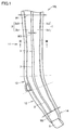
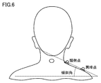
- FIG. 1 It is a front view of the shoulder belt which concerns on this embodiment. It is a rear view of the shoulder belt which concerns on this embodiment. It is sectional drawing seen from the arrow III-III in FIG. It is a figure which shows the backpack which is an example of the bag provided with the shoulder belt which concerns on this embodiment. It is a figure which shows the golf bag which is another example of the bag provided with the shoulder belt which concerns on this embodiment. It is a schematic diagram for demonstrating the cervical side point and the acromion point of a wearer, and the inclination angle of the cervical side point and the acromion point with respect to a horizontal plane.
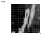
- FIG. 8 is a three-dimensional view showing the load distribution applied to the shoulder measured by using the flexible piezoelectric sensor in the case shown in FIG.
- FIG. 11 is a diagram showing the distance between the cervical side point and the acromion point in the first state shown in FIG.
- FIG. 11 is a diagram showing the distance between the cervical side point and the acromion point in the second state shown in FIG.
- FIG. 11 is a diagram showing the distance between the cervical side point and the acromion point in the third state shown in FIG.
- FIG. 18 is a three-dimensional view showing the load distribution applied to the shoulder measured by using the flexible piezoelectric sensor in the case shown in FIG.
- the shoulder belt according to the present embodiment is attached to the bag and allows the wearer's shoulders and arms to pass through.
- the shoulder belt 10L shown in FIGS. 1 and 2 is for passing the left arm, shoulder and chest of the wearer in the shoulder bag 100 shown in FIG.
- the shoulder belt 10R through which the wearer's right arm, shoulder and chest are passed is symmetrical with the shoulder belt 10L.
- the outside of the bag 100 shown in FIG. 4 is the front side, the opposite side thereof is the back side, the front side surface is the front side, and the back side surface is the back side.
- the shoulder belt 10L has a longitudinal direction and a lateral direction intersecting the longitudinal direction.
- the shoulder belt 10L includes a first part 1, a second part 2, and a third part 3.
- Each of the first part 1 and the second part 2 extends along the longitudinal direction.
- the third part 3 extends between one end and the other end of each of the first part 1 and the second part 2 in the longitudinal direction. In other words, the third part 3 closes between the first part 1 and the second part 2.
- the first part 1 and the second part 2 are arranged so as to be spaced apart from each other in the lateral direction.
- the third part 3 connects between the first part 1 and the second part 2.
- the first part 1 is arranged outside the third part 3 in the bag 100 shown in FIG.
- the second part 2 is arranged inside the third part 3 in the bag 100 shown in FIG.
- the third part 3 is arranged between the first part 1 and the second part 2 in the bag 100 shown in FIG.
- the expansion / contraction rate of the third part 3 is higher than the expansion / contraction rate of each of the first part 1 and the second part 2.
- the elastic modulus of each of the first part 1, the second part 2, and the third part 3 is the elongation elastic modulus defined in the JIS standard (JIS L 1096: 2010), and is defined in the standard, for example. It is measured based on the B-1 method (constant load method).
- the flexibility of Part 3 3 is higher than the flexibility of each of Part 1 1 and Part 2 2. That is, the third part 3 is softer than each of the first part 1 and the second part 2.
- the flexibility of each of the first part 1, the second part 2, and the third part 3 is, for example, the rigidity defined in the JIS standard (JIS L 1096: 2010), for example, A defined in the standard. Measured based on the method (45 ° cantilever method). That is, the rigidity of the third part 3 is lower than the rigidity of each of the first part 1 and the second part 2.
- the shoulder belt 10L is divided into, for example, the first region 11, the second region 12, the third region 13, and the fourth region 14 in the longitudinal direction.
- the first region 11 is connected to the second region 12 via the third region 13.
- the fourth region 14 is arranged on the side opposite to the third region 13 with respect to the second region 12, and is connected to the second region 12.
- the first region 11, the third region 13, the second region 12, and the fourth region 14 are connected in this description order.
- Each of the first part 1, the second part 2, and the third part 3 extends from the first region 11 to the second region 12 in the longitudinal direction of the shoulder belt 10L.
- the first area 11 is an area scheduled to come into contact with the wearer's shoulders and the upper part of the chest when the bag 100 shown in FIG. 4 is worn.
- the second region 12 is a region scheduled to come into contact with the wearer's flank when the bag 100 shown in FIG. 4 is attached.
- the third region 13 is an region that is intended to come into contact with the lower part of the chest and the flank of the wearer when the bag 100 shown in FIG. 4 is worn.
- a connecting member 5 connected to the tape 102 fixed to the lower part of the back surface of the main body storage portion 101 of the bag 100 shown in FIG. 4 is fixed.
- the basic configurations of the first region 11, the second region 12, and the third region 13 are the same as each other.
- Each of the first part 1, the second part 2, and the third part 3 is arranged in each of the first area 11, the second area 12, and the third area 13.
- the basic configurations of the first part 1, the second part 2, and the third part 3 are the same as each other. ..
- each of the first portion 1, the second portion 2, and the third portion 3 extends along the longitudinal direction of the first region 11.
- each of the first part 1, the second part 2, and the third part 3 extends along the longitudinal direction of the second region 12.
- the longitudinal direction of the first region 11 and the longitudinal direction of the second region 12 are along the longitudinal direction of the shoulder belt 10L.
- the lateral direction of the first region 11 and the lateral direction of the second region 12 are along the lateral direction of the shoulder belt 10L.
- the longitudinal direction of the first region 11 is set so as to form a gentle bend with respect to the longitudinal direction of the second region 12.
- the shoulder belt 10L has a bent portion in a plan view.
- the longitudinal length of the second region 12 is shorter than the longitudinal length of the first region 11 and longer than the longitudinal length of the third region 13. It is desirable that the width of the third region 13 in the lateral direction is equal to or narrower than the maximum width W1 in the lateral direction of the first region 11 and wider than the minimum width W2 in the lateral direction of the second region 12.
- width W3 in the lateral direction of the third part 3 in the first region 11 is equal to or greater than the width W3 in the lateral direction of the third part 3 in the second region 12.
- the maximum width W1 in the lateral direction of the first region 11 is 50 mm or more and 90 mm or less
- the minimum width W2 in the lateral direction of the second region 12 is 30 mm or more and 70 mm or less
- the short side of the third part 3 The width W3 in the direction is preferably 5 mm or more and 15 mm or less.
- each of the first part 1 and the second part 2 is configured as, for example, an aggregate of a plurality of members.
- the third part 3 is arranged inside the first part 3a which is arranged inside the first part 1 and is connected to the first part 1, and inside the second part 2.
- the second portion 3b which is connected to the second portion 2, and the first portion 3a and the second portion 3b, which are arranged outside the first portion 3a and the second portion 3b, are connected to each other. Including the third part 3c. In Part 3, Part 3, only the third part 3c is exposed.
- the first part 1 has a core material 1a and a packaging material 1b.
- the core material 1a is arranged so as to overlap with at least a part of the first portion 3a of the third portion 3 in a plan view.
- the packaging material 1b is arranged so as to surround the first portion 3a and the core material 1a in the cross section perpendicular to the longitudinal direction, and is fixed to the first portion 3a.
- the packaging material 1b has, for example, a front surface portion 1b1, a back surface portion 1b2, and an outer edge portion 1b3.
- the packaging material 1b does not have to have the outer edge portion 1b3.
- the surface portion 1b1 is arranged on the core material 1a side with respect to the first portion 3a in the above cross section.
- the back surface portion 1b2 is arranged on the opposite side of the core material 1a with respect to the first portion 3a in the above cross section.
- the outer edge portion 1b3 is arranged outside the first portion 3a, the core material 1a, the front surface portion 1b1, and the back surface portion 1b2 of the third portion 3 in the above cross section.
- the first portion 3a, the surface portion 1b1, and the outer edge portion 1b3 of the third portion 3 are arranged so as to surround the core material 1a.
- the first portion 3a, the core material 1a, the front surface portion 1b1, the back surface portion 1b2, and the outer edge portion 1b3 of the third part 3 are sewn together by, for example, a sewing member 6a.
- the sewing member 6a sews, for example, the outer portions of the first portion 3a, the core material 1a, the front surface portion 1b1, and the back surface portion 1b2, and the inner portion of the outer edge portion 1b3.
- the first portion 3a, the front surface portion 1b1, and the back surface portion 1b2 of the third portion 3 are sewn to each other by, for example, a sewing member 7a.
- the sewing member 7a is sewn, for example, to the inner portions of the first portion 3a, the front surface portion 1b1, and the back surface portion 1b2.
- the second part 2 has a substantially line-symmetrical relationship with the first part 1 with respect to the third part 3c of the third part 3 in the above cross section, for example.
- the second part 2 does not have to have a substantially line-symmetrical relationship with the first part 1 with respect to the third part 3c of the third part 3 in the above cross section.
- the widths of the first part and the second part in the lateral direction may be different from each other.
- the second part 2 has a core material 2a and a packaging material 2b.
- the core material 2a is arranged so as to overlap with at least a part of the second portion 3b of the third portion 3 in a plan view.
- the packaging material 2b is arranged so as to surround the second portion 3b and the core material 2a in the cross section perpendicular to the longitudinal direction, and is fixed to the second portion 3b.
- the packaging material 2b has, for example, a front surface portion 2b1, a back surface portion 2b2, and an outer edge portion 2b3.
- the packaging material 2b does not have to have the outer edge portion 2b3.
- the surface portion 2b1 is arranged on the core material 2a side with respect to the second portion 3b in the above cross section.
- the back surface portion 2b2 is arranged on the side opposite to the core material 2a with respect to the second portion 3b in the above cross section.
- the outer edge portion 2b3 is arranged outside the second portion 3b of the third portion 3, the core material 2a, the front surface portion 2b1, and the back surface portion 2b2 in the above cross section.
- the second portion 3b, the surface portion 2b1, and the outer edge portion 2b3 of the third portion 3 are arranged so as to surround the core material 2a.
- the second portion 3b, the core material 2a, the front surface portion 2b1, the back surface portion 2b2, and the outer edge portion 2b3 of the third portion 3 are sewn together by, for example, a sewing member 6b.
- the sewing member 6b sews, for example, the outer portions of the second portion 3b, the core material 2a, the front surface portion 2b1, and the back surface portion 2b2, and the inner portion of the outer edge portion 2b3.
- the second portion 3b, the front surface portion 2b1, and the back surface portion 2b2 of the third portion 3 are sewn to each other by, for example, a sewing member 7b.
- the sewing member 7b is sewn, for example, to the inner portions of the second portion 3b, the front surface portion 2b1, and the back surface portion 2b2.
- the material constituting the third part 3 includes at least one selected from the group consisting of mesh, air mesh, knit, and stretch material.
- the material constituting the core material 1a includes at least one selected from the group consisting of EPE, EVA, and sponge.
- the material constituting the packaging material 1b includes at least one selected from the group consisting of PU, polyester, nylon, cotton, acrylic and TPU.
- the plurality of members included in each of the first part 1 and the second part 2 are not limited to sewing, and may be fixed to each other by any method such as adhesion.
- the bag 100 provided with the shoulder belt 10L is configured as, for example, a backpack.
- the bag 100 includes a shoulder belt 10L shown in FIGS. 1 to 3, a shoulder belt 10R, and a main body storage portion 101.
- the first region 11 of the shoulder belt 10L is connected to the upper part of the main body storage portion 101.
- the connecting member 5 of the shoulder belt 10L is connected to the tape 102 fixed to the lower part of the main body storage portion 101.
- the tape 102 fixed to the lower part of the main body storage portion 101 is passed through the connecting member 5 of the shoulder belt 10L.
- the connecting member 5 and the tape 102 are provided so as to adjust the length between one end of the tape 102 fixed to the main body accommodating portion 101 and the portion passed through the connecting member 5.
- the shoulder belts 10L and 10L shown in FIGS. 1 to 4 have a bent portion in a plan view, but the shoulder belt according to the present embodiment does not have to have a bent portion in a plan view. ..
- FIG. 5 shows a bag 110 provided with a shoulder belt 10 having no bent portion in a plan view.
- the shoulder belt 10 has basically the same configuration as the shoulder belt 10L, but differs from the shoulder belt 10L in that it does not have a bent portion in a plan view.
- the bag 110 is configured as, for example, a golf bag.
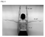
- the shoulder belts 10L, 10R, 10 are scheduled to come into contact with at least a part of the region located between the wearer's cervical side point and the acromion point shown in FIG.
- the third part 3 is planned to be arranged so as to overlap a part of the area located between the wearer's cervical side point and the acromion point.
- the inclination angle formed by the virtual line segment connecting the cervical side point and the acromion point with respect to the horizontal plane, and the distance between the cervical side point and the acromion point differ depending on the wearer.
- the shoulder belt according to the comparative example shown in FIGS. 17 and 18 does not include the third part 3.
- the expansion / contraction ratios on the outer and inner sides are the same as the expansion / contraction ratios on both ends in the lateral direction.
- the flexibility of the central portion in the lateral direction is equivalent to the flexibility of both ends in the lateral direction.
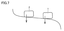
- the shoulder belt according to the comparative example has a relatively small inclination angle, that is, when the shoulder belt is worn by the wearer, the end portion of the shoulder belt in the lateral direction is in the vicinity of the cervical side point. Easy to contact only the part.
- the load of the bag tends to be concentrated in the vicinity of the cervical side point.
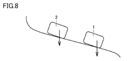
- the shoulder belt according to the comparative example when worn by the wearer, the shoulder belt having a relatively large inclination angle, that is, the so-called stroking shoulder, tends to come into contact with only the portion near the acromion point. Therefore, the load of the bag tends to be concentrated in the vicinity of the acromion point.
- the shoulder belts 10L, 10R, and 10 include the third part 3, and the expansion / contraction rate of the third part 3 is higher than the expansion / contraction rate of each of the first part 1 and the second part 2. It is high and the rigidity of the third part 3 is lower than the rigidity of each of the first part 1 and the second part 2. Therefore, the third part 3 is easily deformed in the short direction and the direction orthogonal to each of the longitudinal direction and the short direction, and the first part 1 and the first part 3 in the short direction and the orthogonal direction. The relative positional relationship between the two parts 2 can be easily changed.
- the first part 1 is the acromion point.
- the second part 2 can contact the vicinity part of the cervical side point while contacting the vicinity part of the cervical side point.
- Part 1 1 can contact the portion near the acromion point
- the second part 2 can contact the portion near the cervical side point.
- the load can be widely distributed between the cervical side point and the acromion point regardless of the inclination angle.
- FIGS. 7 and 8 only the first part 1 and the second part 2 are schematically shown.
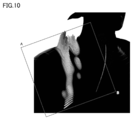
- FIGS. 9 and 10 and FIGS. 19 and 20 are diagrams showing the load distribution applied to the shoulders of the same wearer measured under the same conditions for each of the shoulder belt 10L and the shoulder belt according to the comparative example. ..
- the wearer was a shoulder with a relatively large tilt angle, as shown in FIGS. 8 and 18.
- the load distribution was measured using a flexible piezoelectric sensor fixed to the wearer's shoulder.
- the angles A and B of the measurement area shown in FIGS. 9 and 19 correspond to the angles A and B of the measurement area in FIGS. 10 and 20.
- the right side is the cervical side and the left side is the acromion point side. Further, in FIGS.
- the upper side is the back side of the wearer, and the lower side is the chest side of the wearer.
- the unloaded area is shown in the same color as the background color (the color of the area outside the two inclined lines), and the shades of the colors in the other areas are shown.
- the magnitude of the load applied to the region is shown.
- the heights and shades of color of the plurality of rod-shaped data protruding outward from the body surface indicate the magnitude of the load applied to the region.
- the inclined line located on the right side indicates that it passes through the cervical side point
- the inclined line located on the left side indicates that it passes through the acromion point.
- the load is concentrated in the vicinity of the acromion point, and a relatively large load is applied to the area where the load is applied. Was there.
- the load is distributed in the vicinity of the cervical side point and the vicinity of the acromion point, and a plurality of regions to which the load is applied are applied.
- the maximum load applied to was smaller than the maximum load measured by the shoulder belt according to the comparative example.
- the shoulder belts 10L, 10R, and 10 according to the present embodiment can follow the complicated three-dimensional shape of the body in the static state as compared with the shoulder belts according to the comparative example. ..
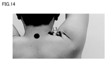
- FIGS. 11 to 14 are diagrams for explaining that the distance between the cervical side point and the acromion point fluctuates in the above dynamic state.
- the first state P1 in which the arm is lowered the second state P2 in which the arm is raised along the horizontal direction, and the arm are raised along the vertical direction.
- the distance L2 (see FIG. 13) between the cervical side point and the acromion point in the second state P2 is the cervical side point and the acromion point in the first state P1. It is shorter than the distance L1 (see FIG. 12) and longer than the distance L3 (see FIG. 14) between the cervical side point and the acromion point in the third state P3.
- Table 1 shows individual differences between the distances L1, the distance L2, and the distance L3. For each of the six subjects, the distance L1, the distance L2, and the distance L3 were measured, and the rate of change thereof was calculated.
- the distance L2 was shorter than the distance L1 and longer than the distance L3.
- the ratio (L2-L1) / L1 was 30% or more in absolute value for all subjects, and the ratio (L3-L1) / L1 was 50% or more in absolute value for all subjects. That is, it was confirmed that the distance between the cervical side point and the acromion point changed significantly in all the subjects in the above-mentioned dynamic state.
- individual differences were confirmed in each of the distance L1, the distance L2, the distance L3, the ratio (L2-L1) / L1, and the ratio (L3-L1) / L1.
- the third part 3 is provided, the expansion / contraction rate of the third part 3 is higher than the expansion / contraction rate of each of the first part 1 and the second part 2, and the third part 3
- the rigidity of the first part 1 and the second part 2 is lower than the rigidity of each of the first part 1 and the second part 2. Therefore, the third part 3 is easily deformed in the short direction and the direction orthogonal to each of the longitudinal direction and the short direction, and the first part 1 and the first part 3 in the short direction and the orthogonal direction.
- the relative positional relationship between the two parts 2 can be easily changed. Therefore, the shoulder belts 10L, 10R, and 10 according to the present embodiment can follow the change in the three-dimensional shape of the body in the above dynamic state.
- the third part 3 of the first region 11 in contact with the shoulder extends linearly in the lateral direction, so that the third portion 3 and the third portion 3 in the lateral direction are formed.
- the continuous first part 1 and second part 2 can be opened in the lateral direction.
- the third portion 3 of the first region 11 in contact with the shoulder bends downward in a convex shape, so that the third portion 3 is bent downward in the lateral direction.
- the first part 1 and the second part 2 which are connected to the third part 3 can also be bent downward in a convex shape. Therefore, in the third state, the first part 1 and the second part 2 can be closed in the short side as compared with the second state.
- the shoulder belts 10L, 10R, 10 since the first region 11 can follow the change in the three-dimensional shape of the shoulder in each of the second state and the third state, the contact between the first region 11 and the shoulder. The area will be large.
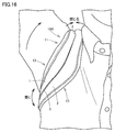
- the second region 12 passed under the armpit is the first region 11 in contact with the shoulder in the second state and the third state. Shows the opposite behavior. Specifically, as shown in FIG. 15, in the second state, the third part 3 of the second region 12 passed under the armpit contracts in the lateral direction. As a result, in the shoulder belts 10L, 10R, and 10, in the second state, the second region 12 is less likely to bite into the armpit and interfere with the arm and flank while ensuring a sufficient contact area with the flank. .. On the other hand, as shown in FIG. 16, in the third state, the third part 3 of the second region 12 passed under the armpit extends along the lateral direction. As a result, in the shoulder belts 10L, 10R, 10, the contact area between the second region 12 and the flank is sufficiently secured in the third state, so that the behavior of the bags 100, 110 is stable in the dynamic state. ..
Landscapes
- Purses, Travelling Bags, Baskets, Or Suitcases (AREA)
- Portable Outdoor Equipment (AREA)
Abstract
L'invention concerne une bandoulière (10L), présentant une direction longitudinale et une direction transversale croisant la direction longitudinale, comprenant : une première partie (1) et une seconde partie (2) qui sont disposées de façon à être espacées l'une de l'autre dans la direction transversale dans une section transversale croisant la direction longitudinale; et une troisième partie (3) qui relie la première partie et la seconde partie. Le rapport d'expansion/contraction de la troisième partie est supérieur au rapport d'expansion/contraction de chacune de la première partie et de la seconde partie. La résistance à la flexion de la troisième partie est inférieure à la résistance à la flexion de chacune de la première partie et de la seconde partie.
Priority Applications (2)
| Application Number | Priority Date | Filing Date | Title |
|---|---|---|---|
| US17/923,941 US12317987B2 (en) | 2020-05-28 | 2021-02-02 | Shoulder belt and bag |
| DE112021002320.9T DE112021002320T5 (de) | 2020-05-28 | 2021-02-02 | Schultergurt und Tasche |
Applications Claiming Priority (2)
| Application Number | Priority Date | Filing Date | Title |
|---|---|---|---|
| JP2020093208A JP7229966B2 (ja) | 2020-05-28 | 2020-05-28 | ショルダーベルトおよびバッグ |
| JP2020-093208 | 2020-05-28 |
Publications (1)
| Publication Number | Publication Date |
|---|---|
| WO2021240887A1 true WO2021240887A1 (fr) | 2021-12-02 |
Family
ID=78744224
Family Applications (1)
| Application Number | Title | Priority Date | Filing Date |
|---|---|---|---|
| PCT/JP2021/003673 Ceased WO2021240887A1 (fr) | 2020-05-28 | 2021-02-02 | Bandoulière et sac |
Country Status (4)
| Country | Link |
|---|---|
| US (1) | US12317987B2 (fr) |
| JP (1) | JP7229966B2 (fr) |
| DE (1) | DE112021002320T5 (fr) |
| WO (1) | WO2021240887A1 (fr) |
Citations (3)
| Publication number | Priority date | Publication date | Assignee | Title |
|---|---|---|---|---|
| JPH1146859A (ja) * | 1997-08-01 | 1999-02-23 | Aban:Kk | ショルダーバッグ |
| JP2001017227A (ja) * | 1999-07-08 | 2001-01-23 | Mizuno Corp | ショルダーベルト |
| JP2004065462A (ja) * | 2002-08-05 | 2004-03-04 | Sankyo Sogyo:Kk | ランドセル用背負いバンドの大紐 |
Family Cites Families (10)
| Publication number | Priority date | Publication date | Assignee | Title |
|---|---|---|---|---|
| US5419475A (en) * | 1992-03-17 | 1995-05-30 | Taisei Plas Co., Ltd. | Shoulder belt |
| US5695102A (en) * | 1995-04-28 | 1997-12-09 | William R. Heckerman | Elastic shoulder strap |
| US5961019A (en) * | 1997-07-09 | 1999-10-05 | K-2 Corporation | Backpack load distribution pad |
| US6915932B1 (en) * | 2003-01-13 | 2005-07-12 | Nike, Inc. | Strap incorporating a fluid-filled bladder |
| US7004363B2 (en) * | 2003-03-21 | 2006-02-28 | Tumi, Inc. | Shoulder strap pad |
| US7448522B2 (en) * | 2003-11-11 | 2008-11-11 | Nike, Inc. | Fluid-filled bladder for use with strap |
| US20050258205A1 (en) * | 2004-05-21 | 2005-11-24 | Michaels Of Oregon Co. | Shock-absorbing carrying strap |
| US9204708B2 (en) * | 2006-05-12 | 2015-12-08 | Nike, Inc. | Strap incorporating a fluid-filled bladder |
| EP2400867A4 (fr) * | 2009-02-26 | 2012-10-17 | Daymen Canada Acquisition Ulc | Dispositif de sangle profilé et réglable et procédé associé |
| JP5877407B2 (ja) * | 2011-06-21 | 2016-03-08 | 株式会社やまびこ | 背負バンドの取付構造 |
-
2020
- 2020-05-28 JP JP2020093208A patent/JP7229966B2/ja active Active
-
2021
- 2021-02-02 WO PCT/JP2021/003673 patent/WO2021240887A1/fr not_active Ceased
- 2021-02-02 DE DE112021002320.9T patent/DE112021002320T5/de active Pending
- 2021-02-02 US US17/923,941 patent/US12317987B2/en active Active
Patent Citations (3)
| Publication number | Priority date | Publication date | Assignee | Title |
|---|---|---|---|---|
| JPH1146859A (ja) * | 1997-08-01 | 1999-02-23 | Aban:Kk | ショルダーバッグ |
| JP2001017227A (ja) * | 1999-07-08 | 2001-01-23 | Mizuno Corp | ショルダーベルト |
| JP2004065462A (ja) * | 2002-08-05 | 2004-03-04 | Sankyo Sogyo:Kk | ランドセル用背負いバンドの大紐 |
Also Published As
| Publication number | Publication date |
|---|---|
| US12317987B2 (en) | 2025-06-03 |
| JP7229966B2 (ja) | 2023-02-28 |
| DE112021002320T5 (de) | 2023-01-26 |
| JP2021186188A (ja) | 2021-12-13 |
| US20230172342A1 (en) | 2023-06-08 |
Similar Documents
| Publication | Publication Date | Title |
|---|---|---|
| US7452376B2 (en) | Flexible, non-planar annuloplasty rings | |
| CN108463129B (zh) | 具有罩杯部的衣服 | |
| JP5429704B2 (ja) | 手袋 | |
| JPH0835105A (ja) | ブラジャーのフレーム | |
| JP6407392B1 (ja) | 腰用サポーター | |
| KR102181779B1 (ko) | 백팩용 어깨끈 및 이를 구비한 백팩 | |
| JP7522524B1 (ja) | ブラカップを有する衣類 | |
| WO2021240887A1 (fr) | Bandoulière et sac | |
| US319404A (en) | goeton | |
| JP2008081900A (ja) | ウェア | |
| JP7557623B2 (ja) | 胸補整及び胸椎矯正用女性向け上衣 | |
| JP4547546B2 (ja) | 腰部保護パッド | |
| US20240122748A1 (en) | Holder for heating and cooling tool | |
| JPH11229206A (ja) | パッド | |
| US20220378118A1 (en) | Brassiere | |
| JP2018119222A (ja) | 水着 | |
| JP3184808B2 (ja) | ブラジャー等における肩ひもずれ防止構造 | |
| KR102704050B1 (ko) | 와블링을 획기적으로 감소시키는 보강재를 포함하는 본넬 스프링 침대 매트리스 | |
| JP6966163B1 (ja) | 衣類 | |
| JP7011844B2 (ja) | 女性用ボトム下着 | |
| KR200386513Y1 (ko) | 브래지어 길이 연장구 | |
| CN223298604U (zh) | 内衣 | |
| CN211483176U (zh) | 飞织后脚跟垫及飞织鞋 | |
| JP2021101051A (ja) | カップ付き衣類 | |
| JP4471570B2 (ja) | 布製装身品用芯材 |
Legal Events
| Date | Code | Title | Description |
|---|---|---|---|
| 121 | Ep: the epo has been informed by wipo that ep was designated in this application |
Ref document number: 21814254 Country of ref document: EP Kind code of ref document: A1 |
|
| 122 | Ep: pct application non-entry in european phase |
Ref document number: 21814254 Country of ref document: EP Kind code of ref document: A1 |
|
| WWG | Wipo information: grant in national office |
Ref document number: 17923941 Country of ref document: US |