WO2021240887A1 - Shoulder belt and bag - Google Patents
Shoulder belt and bag Download PDFInfo
- Publication number
- WO2021240887A1 WO2021240887A1 PCT/JP2021/003673 JP2021003673W WO2021240887A1 WO 2021240887 A1 WO2021240887 A1 WO 2021240887A1 JP 2021003673 W JP2021003673 W JP 2021003673W WO 2021240887 A1 WO2021240887 A1 WO 2021240887A1
- Authority
- WO
- WIPO (PCT)
- Prior art keywords
- shoulder belt
- shoulder
- region
- longitudinal direction
- bag
- Prior art date
- Legal status (The legal status is an assumption and is not a legal conclusion. Google has not performed a legal analysis and makes no representation as to the accuracy of the status listed.)
- Ceased
Links
Images


Classifications
-
- A—HUMAN NECESSITIES
- A45—HAND OR TRAVELLING ARTICLES
- A45F—TRAVELLING OR CAMP EQUIPMENT: SACKS OR PACKS CARRIED ON THE BODY
- A45F3/00—Travelling or camp articles; Sacks or packs carried on the body
- A45F3/04—Sacks or packs carried on the body by means of two straps passing over the two shoulders
-
- A—HUMAN NECESSITIES
- A45—HAND OR TRAVELLING ARTICLES
- A45F—TRAVELLING OR CAMP EQUIPMENT: SACKS OR PACKS CARRIED ON THE BODY
- A45F3/00—Travelling or camp articles; Sacks or packs carried on the body
- A45F3/12—Shoulder-pads
-
- A—HUMAN NECESSITIES
- A45—HAND OR TRAVELLING ARTICLES
- A45F—TRAVELLING OR CAMP EQUIPMENT: SACKS OR PACKS CARRIED ON THE BODY
- A45F3/00—Travelling or camp articles; Sacks or packs carried on the body
- A45F3/02—Sacks or packs carried on the body by means of one strap passing over the shoulder
Definitions
- the present invention relates to a shoulder belt and a bag.
- both ends including a core material and between both ends including a band-shaped tape are provided in a cross section in the longitudinal direction of the shoulder belt.
- a shoulder belt has been proposed that includes a central part to connect to.
- Japanese Patent Application Laid-Open No. 2001-17227 discloses that a tough material such as polypropylene is used for the strip-shaped tape in order to bear the strength of the shoulder belt.
- the shoulder belt is passed through the shoulder belt, and when the wearer's shoulders and arms are in a static state with the arms not moving and lowered, the load can be distributed by following the three-dimensional shape of the body.
- the wearer's shoulders and arms are in a dynamic state, such as when raising and lowering the arms, the change in the three-dimensional shape cannot be sufficiently followed and the contact area between the shoulder belt and the shoulder becomes small. was there.
- the cause was that the central portion including the band-shaped tape had high rigidity, so that both ends and the central portion tended to be flat and the expansion and contraction were small.
- a main object of the present invention is that the contact area between the shoulder belt and the shoulder is not impaired even when the wearer's shoulder and arm are in a dynamic state such as when raising and lowering the arm, as compared with the conventional shoulder belt.
- the shoulder belt according to the present invention is a shoulder belt having a longitudinal direction and a lateral direction intersecting the longitudinal direction, and is arranged at a distance from each other in the lateral direction in a cross section intersecting the longitudinal direction. It includes a part and a second part, and a third part connecting between the first part and the second part.
- the expansion / contraction rate of the third part is higher than the expansion / contraction rate of each of the first part and the second part.
- the rigidity of the third part is lower than the rigidity of each of the first part and the second part.
- each of the first part and the second part extends along the longitudinal direction.
- the third portion extends in the longitudinal direction between one end and the other end of each of the first and second portions.
- each of the first part, the second part, and the third part extends between one end and the other end in the longitudinal direction of the shoulder belt.
- the third part is arranged inside the first part and connected to the first part, and the third part is arranged inside the second part and connected to the second part. It includes a second portion that is formed and a third portion that is arranged outside the first portion and the second portion and connects the first portion and the second portion.
- Each of the first part and the second part has a core material arranged so as to overlap at least a part of the first part or the second part in a plan view, and a first part or a second part and a core in a cross section. It includes a packaging material that is arranged so as to surround the material and is fixed to the first or second part.
- the bag according to the present invention includes the shoulder belt and a main body storage portion fixed to one end and the other end of the shoulder belt in the longitudinal direction.
- the bag is, for example, a backpack or a golf bag.
- the contact area between the shoulder belt and the shoulder is not impaired even when the wearer's shoulder and the arm are in a dynamic state such as when raising and lowering the arm.
- a bag with a belt and the shoulder belt can be provided.
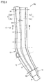
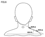
- FIG. 1 It is a front view of the shoulder belt which concerns on this embodiment. It is a rear view of the shoulder belt which concerns on this embodiment. It is sectional drawing seen from the arrow III-III in FIG. It is a figure which shows the backpack which is an example of the bag provided with the shoulder belt which concerns on this embodiment. It is a figure which shows the golf bag which is another example of the bag provided with the shoulder belt which concerns on this embodiment. It is a schematic diagram for demonstrating the cervical side point and the acromion point of a wearer, and the inclination angle of the cervical side point and the acromion point with respect to a horizontal plane.
- FIG. 8 is a three-dimensional view showing the load distribution applied to the shoulder measured by using the flexible piezoelectric sensor in the case shown in FIG.
- FIG. 11 is a diagram showing the distance between the cervical side point and the acromion point in the first state shown in FIG.
- FIG. 11 is a diagram showing the distance between the cervical side point and the acromion point in the second state shown in FIG.
- FIG. 11 is a diagram showing the distance between the cervical side point and the acromion point in the third state shown in FIG.
- FIG. 18 is a three-dimensional view showing the load distribution applied to the shoulder measured by using the flexible piezoelectric sensor in the case shown in FIG.
- the shoulder belt according to the present embodiment is attached to the bag and allows the wearer's shoulders and arms to pass through.
- the shoulder belt 10L shown in FIGS. 1 and 2 is for passing the left arm, shoulder and chest of the wearer in the shoulder bag 100 shown in FIG.
- the shoulder belt 10R through which the wearer's right arm, shoulder and chest are passed is symmetrical with the shoulder belt 10L.
- the outside of the bag 100 shown in FIG. 4 is the front side, the opposite side thereof is the back side, the front side surface is the front side, and the back side surface is the back side.
- the shoulder belt 10L has a longitudinal direction and a lateral direction intersecting the longitudinal direction.
- the shoulder belt 10L includes a first part 1, a second part 2, and a third part 3.
- Each of the first part 1 and the second part 2 extends along the longitudinal direction.
- the third part 3 extends between one end and the other end of each of the first part 1 and the second part 2 in the longitudinal direction. In other words, the third part 3 closes between the first part 1 and the second part 2.
- the first part 1 and the second part 2 are arranged so as to be spaced apart from each other in the lateral direction.
- the third part 3 connects between the first part 1 and the second part 2.
- the first part 1 is arranged outside the third part 3 in the bag 100 shown in FIG.
- the second part 2 is arranged inside the third part 3 in the bag 100 shown in FIG.
- the third part 3 is arranged between the first part 1 and the second part 2 in the bag 100 shown in FIG.
- the expansion / contraction rate of the third part 3 is higher than the expansion / contraction rate of each of the first part 1 and the second part 2.
- the elastic modulus of each of the first part 1, the second part 2, and the third part 3 is the elongation elastic modulus defined in the JIS standard (JIS L 1096: 2010), and is defined in the standard, for example. It is measured based on the B-1 method (constant load method).
- the flexibility of Part 3 3 is higher than the flexibility of each of Part 1 1 and Part 2 2. That is, the third part 3 is softer than each of the first part 1 and the second part 2.
- the flexibility of each of the first part 1, the second part 2, and the third part 3 is, for example, the rigidity defined in the JIS standard (JIS L 1096: 2010), for example, A defined in the standard. Measured based on the method (45 ° cantilever method). That is, the rigidity of the third part 3 is lower than the rigidity of each of the first part 1 and the second part 2.
- the shoulder belt 10L is divided into, for example, the first region 11, the second region 12, the third region 13, and the fourth region 14 in the longitudinal direction.
- the first region 11 is connected to the second region 12 via the third region 13.
- the fourth region 14 is arranged on the side opposite to the third region 13 with respect to the second region 12, and is connected to the second region 12.
- the first region 11, the third region 13, the second region 12, and the fourth region 14 are connected in this description order.
- Each of the first part 1, the second part 2, and the third part 3 extends from the first region 11 to the second region 12 in the longitudinal direction of the shoulder belt 10L.
- the first area 11 is an area scheduled to come into contact with the wearer's shoulders and the upper part of the chest when the bag 100 shown in FIG. 4 is worn.
- the second region 12 is a region scheduled to come into contact with the wearer's flank when the bag 100 shown in FIG. 4 is attached.
- the third region 13 is an region that is intended to come into contact with the lower part of the chest and the flank of the wearer when the bag 100 shown in FIG. 4 is worn.
- a connecting member 5 connected to the tape 102 fixed to the lower part of the back surface of the main body storage portion 101 of the bag 100 shown in FIG. 4 is fixed.
- the basic configurations of the first region 11, the second region 12, and the third region 13 are the same as each other.
- Each of the first part 1, the second part 2, and the third part 3 is arranged in each of the first area 11, the second area 12, and the third area 13.
- the basic configurations of the first part 1, the second part 2, and the third part 3 are the same as each other. ..
- each of the first portion 1, the second portion 2, and the third portion 3 extends along the longitudinal direction of the first region 11.
- each of the first part 1, the second part 2, and the third part 3 extends along the longitudinal direction of the second region 12.
- the longitudinal direction of the first region 11 and the longitudinal direction of the second region 12 are along the longitudinal direction of the shoulder belt 10L.
- the lateral direction of the first region 11 and the lateral direction of the second region 12 are along the lateral direction of the shoulder belt 10L.
- the longitudinal direction of the first region 11 is set so as to form a gentle bend with respect to the longitudinal direction of the second region 12.
- the shoulder belt 10L has a bent portion in a plan view.
- the longitudinal length of the second region 12 is shorter than the longitudinal length of the first region 11 and longer than the longitudinal length of the third region 13. It is desirable that the width of the third region 13 in the lateral direction is equal to or narrower than the maximum width W1 in the lateral direction of the first region 11 and wider than the minimum width W2 in the lateral direction of the second region 12.
- width W3 in the lateral direction of the third part 3 in the first region 11 is equal to or greater than the width W3 in the lateral direction of the third part 3 in the second region 12.
- the maximum width W1 in the lateral direction of the first region 11 is 50 mm or more and 90 mm or less
- the minimum width W2 in the lateral direction of the second region 12 is 30 mm or more and 70 mm or less
- the short side of the third part 3 The width W3 in the direction is preferably 5 mm or more and 15 mm or less.
- each of the first part 1 and the second part 2 is configured as, for example, an aggregate of a plurality of members.
- the third part 3 is arranged inside the first part 3a which is arranged inside the first part 1 and is connected to the first part 1, and inside the second part 2.
- the second portion 3b which is connected to the second portion 2, and the first portion 3a and the second portion 3b, which are arranged outside the first portion 3a and the second portion 3b, are connected to each other. Including the third part 3c. In Part 3, Part 3, only the third part 3c is exposed.
- the first part 1 has a core material 1a and a packaging material 1b.
- the core material 1a is arranged so as to overlap with at least a part of the first portion 3a of the third portion 3 in a plan view.
- the packaging material 1b is arranged so as to surround the first portion 3a and the core material 1a in the cross section perpendicular to the longitudinal direction, and is fixed to the first portion 3a.
- the packaging material 1b has, for example, a front surface portion 1b1, a back surface portion 1b2, and an outer edge portion 1b3.
- the packaging material 1b does not have to have the outer edge portion 1b3.
- the surface portion 1b1 is arranged on the core material 1a side with respect to the first portion 3a in the above cross section.
- the back surface portion 1b2 is arranged on the opposite side of the core material 1a with respect to the first portion 3a in the above cross section.
- the outer edge portion 1b3 is arranged outside the first portion 3a, the core material 1a, the front surface portion 1b1, and the back surface portion 1b2 of the third portion 3 in the above cross section.
- the first portion 3a, the surface portion 1b1, and the outer edge portion 1b3 of the third portion 3 are arranged so as to surround the core material 1a.
- the first portion 3a, the core material 1a, the front surface portion 1b1, the back surface portion 1b2, and the outer edge portion 1b3 of the third part 3 are sewn together by, for example, a sewing member 6a.
- the sewing member 6a sews, for example, the outer portions of the first portion 3a, the core material 1a, the front surface portion 1b1, and the back surface portion 1b2, and the inner portion of the outer edge portion 1b3.
- the first portion 3a, the front surface portion 1b1, and the back surface portion 1b2 of the third portion 3 are sewn to each other by, for example, a sewing member 7a.
- the sewing member 7a is sewn, for example, to the inner portions of the first portion 3a, the front surface portion 1b1, and the back surface portion 1b2.
- the second part 2 has a substantially line-symmetrical relationship with the first part 1 with respect to the third part 3c of the third part 3 in the above cross section, for example.
- the second part 2 does not have to have a substantially line-symmetrical relationship with the first part 1 with respect to the third part 3c of the third part 3 in the above cross section.
- the widths of the first part and the second part in the lateral direction may be different from each other.
- the second part 2 has a core material 2a and a packaging material 2b.
- the core material 2a is arranged so as to overlap with at least a part of the second portion 3b of the third portion 3 in a plan view.
- the packaging material 2b is arranged so as to surround the second portion 3b and the core material 2a in the cross section perpendicular to the longitudinal direction, and is fixed to the second portion 3b.
- the packaging material 2b has, for example, a front surface portion 2b1, a back surface portion 2b2, and an outer edge portion 2b3.
- the packaging material 2b does not have to have the outer edge portion 2b3.
- the surface portion 2b1 is arranged on the core material 2a side with respect to the second portion 3b in the above cross section.
- the back surface portion 2b2 is arranged on the side opposite to the core material 2a with respect to the second portion 3b in the above cross section.
- the outer edge portion 2b3 is arranged outside the second portion 3b of the third portion 3, the core material 2a, the front surface portion 2b1, and the back surface portion 2b2 in the above cross section.
- the second portion 3b, the surface portion 2b1, and the outer edge portion 2b3 of the third portion 3 are arranged so as to surround the core material 2a.
- the second portion 3b, the core material 2a, the front surface portion 2b1, the back surface portion 2b2, and the outer edge portion 2b3 of the third portion 3 are sewn together by, for example, a sewing member 6b.
- the sewing member 6b sews, for example, the outer portions of the second portion 3b, the core material 2a, the front surface portion 2b1, and the back surface portion 2b2, and the inner portion of the outer edge portion 2b3.
- the second portion 3b, the front surface portion 2b1, and the back surface portion 2b2 of the third portion 3 are sewn to each other by, for example, a sewing member 7b.
- the sewing member 7b is sewn, for example, to the inner portions of the second portion 3b, the front surface portion 2b1, and the back surface portion 2b2.
- the material constituting the third part 3 includes at least one selected from the group consisting of mesh, air mesh, knit, and stretch material.
- the material constituting the core material 1a includes at least one selected from the group consisting of EPE, EVA, and sponge.
- the material constituting the packaging material 1b includes at least one selected from the group consisting of PU, polyester, nylon, cotton, acrylic and TPU.
- the plurality of members included in each of the first part 1 and the second part 2 are not limited to sewing, and may be fixed to each other by any method such as adhesion.
- the bag 100 provided with the shoulder belt 10L is configured as, for example, a backpack.
- the bag 100 includes a shoulder belt 10L shown in FIGS. 1 to 3, a shoulder belt 10R, and a main body storage portion 101.
- the first region 11 of the shoulder belt 10L is connected to the upper part of the main body storage portion 101.
- the connecting member 5 of the shoulder belt 10L is connected to the tape 102 fixed to the lower part of the main body storage portion 101.
- the tape 102 fixed to the lower part of the main body storage portion 101 is passed through the connecting member 5 of the shoulder belt 10L.
- the connecting member 5 and the tape 102 are provided so as to adjust the length between one end of the tape 102 fixed to the main body accommodating portion 101 and the portion passed through the connecting member 5.
- the shoulder belts 10L and 10L shown in FIGS. 1 to 4 have a bent portion in a plan view, but the shoulder belt according to the present embodiment does not have to have a bent portion in a plan view. ..
- FIG. 5 shows a bag 110 provided with a shoulder belt 10 having no bent portion in a plan view.
- the shoulder belt 10 has basically the same configuration as the shoulder belt 10L, but differs from the shoulder belt 10L in that it does not have a bent portion in a plan view.
- the bag 110 is configured as, for example, a golf bag.
- the shoulder belts 10L, 10R, 10 are scheduled to come into contact with at least a part of the region located between the wearer's cervical side point and the acromion point shown in FIG.
- the third part 3 is planned to be arranged so as to overlap a part of the area located between the wearer's cervical side point and the acromion point.
- the inclination angle formed by the virtual line segment connecting the cervical side point and the acromion point with respect to the horizontal plane, and the distance between the cervical side point and the acromion point differ depending on the wearer.
- the shoulder belt according to the comparative example shown in FIGS. 17 and 18 does not include the third part 3.
- the expansion / contraction ratios on the outer and inner sides are the same as the expansion / contraction ratios on both ends in the lateral direction.
- the flexibility of the central portion in the lateral direction is equivalent to the flexibility of both ends in the lateral direction.
- the shoulder belt according to the comparative example has a relatively small inclination angle, that is, when the shoulder belt is worn by the wearer, the end portion of the shoulder belt in the lateral direction is in the vicinity of the cervical side point. Easy to contact only the part.
- the load of the bag tends to be concentrated in the vicinity of the cervical side point.
- the shoulder belt according to the comparative example when worn by the wearer, the shoulder belt having a relatively large inclination angle, that is, the so-called stroking shoulder, tends to come into contact with only the portion near the acromion point. Therefore, the load of the bag tends to be concentrated in the vicinity of the acromion point.
- the shoulder belts 10L, 10R, and 10 include the third part 3, and the expansion / contraction rate of the third part 3 is higher than the expansion / contraction rate of each of the first part 1 and the second part 2. It is high and the rigidity of the third part 3 is lower than the rigidity of each of the first part 1 and the second part 2. Therefore, the third part 3 is easily deformed in the short direction and the direction orthogonal to each of the longitudinal direction and the short direction, and the first part 1 and the first part 3 in the short direction and the orthogonal direction. The relative positional relationship between the two parts 2 can be easily changed.
- the first part 1 is the acromion point.
- the second part 2 can contact the vicinity part of the cervical side point while contacting the vicinity part of the cervical side point.
- Part 1 1 can contact the portion near the acromion point
- the second part 2 can contact the portion near the cervical side point.
- the load can be widely distributed between the cervical side point and the acromion point regardless of the inclination angle.
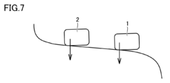
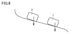
- FIGS. 7 and 8 only the first part 1 and the second part 2 are schematically shown.
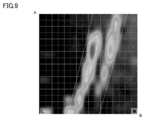
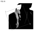
- FIGS. 9 and 10 and FIGS. 19 and 20 are diagrams showing the load distribution applied to the shoulders of the same wearer measured under the same conditions for each of the shoulder belt 10L and the shoulder belt according to the comparative example. ..
- the wearer was a shoulder with a relatively large tilt angle, as shown in FIGS. 8 and 18.
- the load distribution was measured using a flexible piezoelectric sensor fixed to the wearer's shoulder.
- the angles A and B of the measurement area shown in FIGS. 9 and 19 correspond to the angles A and B of the measurement area in FIGS. 10 and 20.
- the right side is the cervical side and the left side is the acromion point side. Further, in FIGS.
- the upper side is the back side of the wearer, and the lower side is the chest side of the wearer.
- the unloaded area is shown in the same color as the background color (the color of the area outside the two inclined lines), and the shades of the colors in the other areas are shown.
- the magnitude of the load applied to the region is shown.
- the heights and shades of color of the plurality of rod-shaped data protruding outward from the body surface indicate the magnitude of the load applied to the region.
- the inclined line located on the right side indicates that it passes through the cervical side point
- the inclined line located on the left side indicates that it passes through the acromion point.
- the load is concentrated in the vicinity of the acromion point, and a relatively large load is applied to the area where the load is applied. Was there.
- the load is distributed in the vicinity of the cervical side point and the vicinity of the acromion point, and a plurality of regions to which the load is applied are applied.
- the maximum load applied to was smaller than the maximum load measured by the shoulder belt according to the comparative example.
- the shoulder belts 10L, 10R, and 10 according to the present embodiment can follow the complicated three-dimensional shape of the body in the static state as compared with the shoulder belts according to the comparative example. ..
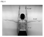
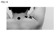
- FIGS. 11 to 14 are diagrams for explaining that the distance between the cervical side point and the acromion point fluctuates in the above dynamic state.
- the first state P1 in which the arm is lowered the second state P2 in which the arm is raised along the horizontal direction, and the arm are raised along the vertical direction.
- the distance L2 (see FIG. 13) between the cervical side point and the acromion point in the second state P2 is the cervical side point and the acromion point in the first state P1. It is shorter than the distance L1 (see FIG. 12) and longer than the distance L3 (see FIG. 14) between the cervical side point and the acromion point in the third state P3.
- Table 1 shows individual differences between the distances L1, the distance L2, and the distance L3. For each of the six subjects, the distance L1, the distance L2, and the distance L3 were measured, and the rate of change thereof was calculated.
- the distance L2 was shorter than the distance L1 and longer than the distance L3.
- the ratio (L2-L1) / L1 was 30% or more in absolute value for all subjects, and the ratio (L3-L1) / L1 was 50% or more in absolute value for all subjects. That is, it was confirmed that the distance between the cervical side point and the acromion point changed significantly in all the subjects in the above-mentioned dynamic state.
- individual differences were confirmed in each of the distance L1, the distance L2, the distance L3, the ratio (L2-L1) / L1, and the ratio (L3-L1) / L1.
- the third part 3 is provided, the expansion / contraction rate of the third part 3 is higher than the expansion / contraction rate of each of the first part 1 and the second part 2, and the third part 3
- the rigidity of the first part 1 and the second part 2 is lower than the rigidity of each of the first part 1 and the second part 2. Therefore, the third part 3 is easily deformed in the short direction and the direction orthogonal to each of the longitudinal direction and the short direction, and the first part 1 and the first part 3 in the short direction and the orthogonal direction.
- the relative positional relationship between the two parts 2 can be easily changed. Therefore, the shoulder belts 10L, 10R, and 10 according to the present embodiment can follow the change in the three-dimensional shape of the body in the above dynamic state.
- the third part 3 of the first region 11 in contact with the shoulder extends linearly in the lateral direction, so that the third portion 3 and the third portion 3 in the lateral direction are formed.
- the continuous first part 1 and second part 2 can be opened in the lateral direction.
- the third portion 3 of the first region 11 in contact with the shoulder bends downward in a convex shape, so that the third portion 3 is bent downward in the lateral direction.
- the first part 1 and the second part 2 which are connected to the third part 3 can also be bent downward in a convex shape. Therefore, in the third state, the first part 1 and the second part 2 can be closed in the short side as compared with the second state.
- the shoulder belts 10L, 10R, 10 since the first region 11 can follow the change in the three-dimensional shape of the shoulder in each of the second state and the third state, the contact between the first region 11 and the shoulder. The area will be large.
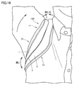
- the second region 12 passed under the armpit is the first region 11 in contact with the shoulder in the second state and the third state. Shows the opposite behavior. Specifically, as shown in FIG. 15, in the second state, the third part 3 of the second region 12 passed under the armpit contracts in the lateral direction. As a result, in the shoulder belts 10L, 10R, and 10, in the second state, the second region 12 is less likely to bite into the armpit and interfere with the arm and flank while ensuring a sufficient contact area with the flank. .. On the other hand, as shown in FIG. 16, in the third state, the third part 3 of the second region 12 passed under the armpit extends along the lateral direction. As a result, in the shoulder belts 10L, 10R, 10, the contact area between the second region 12 and the flank is sufficiently secured in the third state, so that the behavior of the bags 100, 110 is stable in the dynamic state. ..
Landscapes
- Purses, Travelling Bags, Baskets, Or Suitcases (AREA)
- Portable Outdoor Equipment (AREA)
Abstract
Description
本発明は、ショルダーベルトおよびバッグに関する。 The present invention relates to a shoulder belt and a bag.
肩への負荷を低減させるために、ショルダーベルトと肩との接地面積を増やし、荷重を分散させ圧力を低下させる試みが行われている。 Attempts have been made to increase the contact area between the shoulder belt and the shoulder to disperse the load and reduce the pressure in order to reduce the load on the shoulder.
特開2001-17227号公報には、ショルダーベルトを体の複雑な三次元形状に追従させるために、ショルダーベルトの長手方向の断面において、芯材を含む両端部と、帯状テープを含み両端部間を接続する中央部とを含むショルダーベルトが提案されている。さらに、特開2001-17227号公報には、ショルダーベルトの強度を負担するために、帯状テープにはポリプロピレンなどの強靭な素材が用いられることが開示されている。 In Japanese Patent Application Laid-Open No. 2001-17227, in order to make the shoulder belt follow a complicated three-dimensional shape of the body, in a cross section in the longitudinal direction of the shoulder belt, both ends including a core material and between both ends including a band-shaped tape are provided. A shoulder belt has been proposed that includes a central part to connect to. Further, Japanese Patent Application Laid-Open No. 2001-17227 discloses that a tough material such as polypropylene is used for the strip-shaped tape in order to bear the strength of the shoulder belt.
上記ショルダーベルトは、ショルダーベルトに通し、腕が動いていない下げた状態で着用者の肩および腕が静的な状態にあるときには、体の三次元形状に追従でき荷重を分散させることはできる。一方で、腕を上げ下げするときなどの着用者の肩および腕が動的な状態にあるときには、上記三次元形状の変化に十分に追従できず、ショルダーベルトと肩との接地面積が小さくなる場合があった。 The shoulder belt is passed through the shoulder belt, and when the wearer's shoulders and arms are in a static state with the arms not moving and lowered, the load can be distributed by following the three-dimensional shape of the body. On the other hand, when the wearer's shoulders and arms are in a dynamic state, such as when raising and lowering the arms, the change in the three-dimensional shape cannot be sufficiently followed and the contact area between the shoulder belt and the shoulder becomes small. was there.
本発明者らによる研究の結果、帯状テープを含む中央部の剛性が高いために両端部および中央部がフラットとなりやすい、かつ伸び縮みが少ないことがその原因と考えられた。 As a result of the research by the present inventors, it was considered that the cause was that the central portion including the band-shaped tape had high rigidity, so that both ends and the central portion tended to be flat and the expansion and contraction were small.
本発明の主たる目的は、従来のショルダーベルトと比べて、腕を上げ下げするときなどの着用者の肩および腕が動的な状態にあるときにもショルダーベルトと肩との接地面積が損なわれないショルダーベルトおよび該ショルダーベルトを備えるバッグを提供することにある。 A main object of the present invention is that the contact area between the shoulder belt and the shoulder is not impaired even when the wearer's shoulder and arm are in a dynamic state such as when raising and lowering the arm, as compared with the conventional shoulder belt. To provide a shoulder belt and a bag with the shoulder belt.
本発明に係るショルダーベルトは、長手方向および長手方向と交差する短手方向とを有するショルダーベルトであって、長手方向と交差する断面において短手方向に互いに間隔を隔てて配置されている第1部および第2部と、第1部と第2部との間を接続する第3部とを備える。第3部の伸縮率は、第1部および第2部の各々の伸縮率よりも高い。第3部の剛軟度は、第1部および第2部の各々の剛軟度よりも低い。 The shoulder belt according to the present invention is a shoulder belt having a longitudinal direction and a lateral direction intersecting the longitudinal direction, and is arranged at a distance from each other in the lateral direction in a cross section intersecting the longitudinal direction. It includes a part and a second part, and a third part connecting between the first part and the second part. The expansion / contraction rate of the third part is higher than the expansion / contraction rate of each of the first part and the second part. The rigidity of the third part is lower than the rigidity of each of the first part and the second part.
上記ショルダーベルトにおいて、第1部および第2部の各々は、長手方向に沿って延在している。第3部は、長手方向において第1部および第2部の各々の一端と他端との間に延在している。 In the shoulder belt, each of the first part and the second part extends along the longitudinal direction. The third portion extends in the longitudinal direction between one end and the other end of each of the first and second portions.
上記ショルダーベルトにおいて、第1部、第2部、および第3部の各々は、ショルダーベルトの長手方向の一端と他端との間に延在している。 In the shoulder belt, each of the first part, the second part, and the third part extends between one end and the other end in the longitudinal direction of the shoulder belt.
上記ショルダーベルトにおいて、第3部は、第1部の内部に配置されておりかつ第1部に接続されている第1部分と、第2部の内部に配置されておりかつ第2部に接続されている第2部分と、第1部分および第2部分の外部に配置されておりかつ第1部分と第2部分とを接続している第3部分とを含む。第1部および第2部の各々は、平面視において第1部分または第2部分の少なくとも一部と重なるように配置されている芯材と、断面において、第1部分または第2部分、および芯材を囲むように配置されており、かつ第1部分または第2部分と固定されている包材とを含む。 In the shoulder belt, the third part is arranged inside the first part and connected to the first part, and the third part is arranged inside the second part and connected to the second part. It includes a second portion that is formed and a third portion that is arranged outside the first portion and the second portion and connects the first portion and the second portion. Each of the first part and the second part has a core material arranged so as to overlap at least a part of the first part or the second part in a plan view, and a first part or a second part and a core in a cross section. It includes a packaging material that is arranged so as to surround the material and is fixed to the first or second part.
本発明に係るバッグは、上記ショルダーベルトと、ショルダーベルトの長手方向の一端および他端に固定されている本体収納部とを備える。上記バッグは、一例として、バックパックまたはゴルフバッグである。 The bag according to the present invention includes the shoulder belt and a main body storage portion fixed to one end and the other end of the shoulder belt in the longitudinal direction. The bag is, for example, a backpack or a golf bag.
本発明によれば、従来のショルダーベルトと比べて、腕を上げ下げするときなどの着用者の肩および腕が動的な状態にあるときにもショルダーベルトと肩との接地面積が損なわれないショルダーベルトおよび該ショルダーベルトを備えるバッグを提供することができる。 According to the present invention, as compared with the conventional shoulder belt, the contact area between the shoulder belt and the shoulder is not impaired even when the wearer's shoulder and the arm are in a dynamic state such as when raising and lowering the arm. A bag with a belt and the shoulder belt can be provided.
以下、図面を参照して、本発明の実施の形態について説明する。なお、以下の図面において同一または相当する部分には同一の参照番号を付しその説明は繰返さない。 Hereinafter, embodiments of the present invention will be described with reference to the drawings. In the following drawings, the same or corresponding parts will be given the same reference number and the explanation will not be repeated.
本実施の形態に係るショルダーベルトは、バッグに備え付けられて、装着者の肩および腕が通されるものである。図1、図2に示されるショルダーベルト10Lは、図4に示されるショルダーバッグ100において装着者の左側の腕、肩および胸が通されるものである。なお、図4に示されるショルダーバッグ100において装着者の右側の腕、肩および胸が通されるショルダーベルト10Rは、ショルダーベルト10Lと左右対称の関係にある。以下、ショルダーベルト10Lにおいて、図4に示されるバッグ100の外側を表側、その反対側を裏側とし、表側の面を正面、裏側の面を裏面とする。
The shoulder belt according to the present embodiment is attached to the bag and allows the wearer's shoulders and arms to pass through. The
図1および図2に示されるように、ショルダーベルト10Lは、長手方向と、長手方向と交差する短手方向とを有している。
As shown in FIGS. 1 and 2, the
図1~図3に示されるように、ショルダーベルト10Lは、第1部1、第2部2、および第3部3を備える。第1部1および第2部2の各々は、上記長手方向に沿って延在している。第3部3は、上記長手方向において第1部1および第2部2の各々の一端と他端との間に延在している。言い換えると、第3部3は、第1部1と第2部2との間を塞いでいる。
As shown in FIGS. 1 to 3, the
図3に示されるように、上記長手方向と交差する断面において、第1部1および第2部2は、短手方向に互いに間隔を隔てて配置されている。第3部3は、第1部1と第2部2との間を接続している。第1部1は、図4に示されるバッグ100において第3部3よりも外側に配置される。第2部2は、図4に示されるバッグ100において第3部3よりも内側に配置される。第3部3は、図4に示されるバッグ100において第1部1と第2部2との間に配置される。
As shown in FIG. 3, in the cross section intersecting the longitudinal direction, the
第3部3の伸縮率は、第1部1および第2部2の各々の伸縮率よりも高い。ここで、第1部1、第2部2、および第3部3の各伸縮率は、JIS規格(JIS L 1096:2010)に定められた伸長弾性率であり、例えば当該規格に定められたB-1法(定荷重法)に基づいて測定される。
The expansion / contraction rate of the
第3部3の柔軟性は、第1部1および第2部2の各々の柔軟性よりも高い。つまり、第3部3は、第1部1および第2部2の各々より柔らかい。第1部1、第2部2、および第3部3の各々の柔軟性は、例えばJIS規格(JIS L 1096:2010)に定められた剛軟度であり、例えば当該規格に定められたA法(45°カンチレバー法)に基づいて測定される。つまり、第3部3の剛軟度は、第1部1および第2部2の各々の剛軟度よりも低い。
The flexibility of
図1および図2に示されるように、ショルダーベルト10Lは、例えば上記長手方向において第1領域11,第2領域12,第3領域13、および第4領域14に区分される。第1領域11は、第3領域13を介して、第2領域12と接続されている。第4領域14は、第2領域12対して第3領域13とは反対側に配置されており、かつ第2領域12に接続されている。言い換えると、第1領域11、第3領域13、第2領域12、および第4領域14は、この記載順に接続されている。第1部1、第2部2、および第3部3の各々は、ショルダーベルト10Lの長手方向において第1領域11から第2領域12まで延在している。
As shown in FIGS. 1 and 2, the
なお、第1領域11は、図4に示されるバッグ100が装着されたときに、装着者の肩および胸の上部に接触することが予定された領域である。第2領域12は、図4に示されるバッグ100が装着されたときに、装着者の脇腹に接触することが予定された領域である。第3領域13は、図4に示されるバッグ100が装着されたときに、装着者の胸の下部および脇腹に接触することが予定された領域である。第4領域14には、図4に示されるバッグ100の本体収納部101の背面下部に固定されたテープ102と連結される連結部材5が固定されている。
The
第1領域11,第2領域12,および第3領域13の各々の基本的な構成は、互いに同じである。第1部1、第2部2、および第3部3の各々は、第1領域11,第2領域12,および第3領域13の各々に配置されている。言い換えれば、第1領域11,第2領域12,および第3領域13の各々において、第1部1、第2部2、および第3部3の各々の基本的な構成は、互いに同じである。
The basic configurations of the
第1領域11において、第1部1、第2部2、および第3部3の各々は、第1領域11の長手方向に沿って延在している。第2領域12において、第1部1、第2部2、および第3部3の各々は、第2領域12の長手方向に沿って延在している。第1領域11の長手方向および第2領域12の長手方向は、ショルダーベルト10Lの長手方向に沿っている。第1領域11の短手方向および第2領域12の短手方向は、ショルダーベルト10Lの短手方向に沿っている。
In the
第1領域11の長手方向は、第2領域12の長手方向に対してなだらかな屈曲を成すように、設定されている。言い換えると、平面視において、ショルダーベルト10Lは屈曲部を有している。
The longitudinal direction of the
第2領域12の長手方向の長さは、第1領域11の長手方向の長さよりも短く、第3領域13の長手方向の長さよりも長い。第3領域13の短手方向の幅は、第1領域11の短手方向の最大幅W1と同等もしくは狭く、第2領域12の短手方向の最小幅W2よりも広いのが望ましい。
The longitudinal length of the
第1領域11における第3部3の短手方向の幅W3は、第2領域12における第3部3の短手方向の幅W3と同等以上であるのが望ましい。
It is desirable that the width W3 in the lateral direction of the
ショルダーベルト10Lの一例では、第1領域11の短手方向の最大幅W1は50mm以上90mm以下、第2領域12の短手方向の最小幅W2は30mm以上70mm以下、第3部3の短手方向の幅W3は5mm以上15mm以下であるのが望ましい。
In an example of the
図1~図3に示されるように、第1部1および第2部2の各々は、例えば複数の部材の集合体として構成されている。
As shown in FIGS. 1 to 3, each of the
図3に示されるように、第3部3は、第1部1の内部に配置されておりかつ第1部1に接続されている第1部分3aと、第2部2の内部に配置されておりかつ第2部2に接続されている第2部分3bと、第1部分3aおよび第2部分3bの外部に配置されておりかつ第1部分3aと第2部分3bとを接続している第3部分3cとを含む。第3部3において、第3部分3cのみが表出している。
As shown in FIG. 3, the
図3に示されるように、第1部1は、芯材1aと、包材1bとを有している。芯材1aは、平面視において第3部3の第1部分3aの少なくとも一部と重なるように配置されている。包材1bは、上記長手方向に垂直な断面において、第1部分3aおよび芯材1aを囲むように配置されており、かつ第1部分3aと固定されている。包材1bは、例えば表面部1b1と、裏面部1b2と、外縁部1b3とを有している。なお、包材1bは、外縁部1b3を有していなくてもよい。表面部1b1は、上記断面において、第1部分3aに対して芯材1a側に配置されている。裏面部1b2は、上記断面において、第1部分3aに対して芯材1aとは反対側に配置されている。外縁部1b3は、上記断面において、第3部3の第1部分3a、芯材1a、表面部1b1、および裏面部1b2よりも外側に配置されている。第3部3の第1部分3a、表面部1b1、および外縁部1b3は、芯材1aを囲むように配置されている。
As shown in FIG. 3, the
図3に示されるように、第3部3の第1部分3a、芯材1a、表面部1b1、裏面部1b2、および外縁部1b3は、例えば縫着部材6aによって互いに縫着されている。縫着部材6aは、例えば、第1部分3a、芯材1a、表面部1b1、および裏面部1b2の各々の外側部分と、外縁部1b3の内側部分とを縫着している。さらに、第3部3の第1部分3a、表面部1b1、および裏面部1b2は、例えば縫着部材7aによって互いに縫着されている。縫着部材7aは、例えば、第1部分3a、表面部1b1、および裏面部1b2の各々の内側部分を縫着している。
As shown in FIG. 3, the
図3に示されるように、第2部2は、例えば上記断面において第3部3の第3部分3cに対して第1部1と実質的に線対称の関係を有している。なお、第2部2は、上記断面において第3部3の第3部分3cに対して第1部1と実質的に線対称の関係を有していなくてもよい。例えば、上記短手方向における第1部および第2部の各々の幅は、互いに異なっていてもよい。
As shown in FIG. 3, the
図3に示されるように、第2部2は、芯材2aと、包材2bとを有している。芯材2aは、平面視において第3部3の第2部分3bの少なくとも一部と重なるように配置されている。包材2bは、上記長手方向に垂直な断面において、第2部分3bおよび芯材2aを囲むように配置されており、かつ第2部分3bと固定されている。包材2bは、例えば表面部2b1と、裏面部2b2と、外縁部2b3とを有している。なお、包材2bは、外縁部2b3を有していなくてもよい。表面部2b1は、上記断面において、第2部分3bに対して芯材2a側に配置されている。裏面部2b2は、上記断面において、第2部分3bに対して芯材2aとは反対側に配置されている。外縁部2b3は、上記断面において、第3部3の第2部分3b、芯材2a、表面部2b1、および裏面部2b2よりも外側に配置されている。第3部3の第2部分3b、表面部2b1、および外縁部2b3は、芯材2aを囲むように配置されている。
As shown in FIG. 3, the
図3に示されるように、第3部3の第2部分3b、芯材2a、表面部2b1、裏面部2b2、および外縁部2b3は、例えば縫着部材6bによって互いに縫着されている。縫着部材6bは、例えば、第2部分3b、芯材2a、表面部2b1、および裏面部2b2の各々の外側部分と、外縁部2b3の内側部分とを縫着している。さらに、第3部3の第2部分3b、表面部2b1、および裏面部2b2は、例えば縫着部材7bによって互いに縫着されている。縫着部材7bは、例えば、第2部分3b、表面部2b1、および裏面部2b2の各々の内側部分を縫着している。
As shown in FIG. 3, the
ショルダーベルト10Lの一例では、第3部3を構成する材料は、メッシュ、エアメッシュ、ニット、およびストレッチ素材からなる群から選択される少なくとも1つを含む。芯材1aを構成する材料は、EPE、EVA、およびスポンジからなる群から選択される少なくとも1つを含む。包材1bを構成する材料は、PU、ポリエステル、ナイロン、綿、アクリルおよびTPUからなる群から選択される少なくとも1つを含む。なお、第1部1および第2部2の各々に含まれる複数の部材は、縫着に限られず、接着などの任意の方法によって互いに固定されていればよい。
In the example of the
図4に示されるように、ショルダーベルト10Lを備えるバッグ100は、例えばバックパックとして構成されている。図4に示されるように、バッグ100は、図1~図3に示されるショルダーベルト10Lと、ショルダーベルト10Rと、本体収納部101とを備える。ショルダーベルト10Lの第1領域11は、本体収納部101の上部に接続されている。ショルダーベルト10Lの連結部材5は、本体収納部101の下部に固定されたテープ102と連結している。例えば、ショルダーベルト10Lの連結部材5には、本体収納部101の下部に固定されたテープ102が通されている。好ましくは、連結部材5およびテープ102は、テープ102において本体収納部101に固定されている一端と連結部材5に通されている部分との間の長さを調整するように設けられている。
As shown in FIG. 4, the
なお、図1~図4に示されるショルダーベルト10L,10Lは平面視において屈曲部を有しているが、本実施の形態に係るショルダーベルトは平面視において屈曲部を有していなくてもよい。
The
図5は、平面視において屈曲部を有していないショルダーベルト10を備えるバッグ110を示している。ショルダーベルト10は、ショルダーベルト10Lと基本的に同様の構成を備えるが、平面視において屈曲部を有していない点で、ショルダーベルト10Lとは異なる。バッグ110は、例えばゴルフバッグとして構成されている。
FIG. 5 shows a
次に、本実施の形態に係るショルダーベルト10L,10R,10の作用効果を説明する。まず、図6~図10を参照して、装着者の肩および腕が静的な状態にあるときのショルダーベルト10L,10R,10の作用効果を、図17~図19に示される比較例との対比に基づいて説明する。
Next, the action and effect of the
ショルダーベルト10L,10R,10は、図6に示される装着者の頚側点と肩峰点との間に位置する領域の少なくとも一部と接触することが予定されている。第3部3は、装着者の頚側点と肩峰点との間に位置する領域の一部と重なるように配置されることが予定されている。
The
頚側点および肩峰点を結ぶ仮想線分が水平面に対して成す傾斜角、および頚側点と肩峰点との間の距離は、装着者毎に異なる。 The inclination angle formed by the virtual line segment connecting the cervical side point and the acromion point with respect to the horizontal plane, and the distance between the cervical side point and the acromion point differ depending on the wearer.
図17および図18に示される比較例に係るショルダーベルトは、第3部3を備えていない。比較例に係るショルダーベルトにおいて外側及び内側の伸縮率は、短手方向の両端部の伸縮率と同等である。比較例に係るショルダーベルトにおいて短手方向の中央部の柔軟性は、短手方向の両端部の柔軟性と同等である。図17に示されるように、比較例に係るショルダーベルトが上記傾斜角が比較的小さい、いわゆるいかり肩の、装着者に装着されたときには、ショルダーベルトの短手方向の端部が頚側点の近傍部分にのみ接触しやすい。そのため、バッグの荷重は頚側点の近傍部分に集中しやすい。また、図18に示されるように、比較例に係るショルダーベルトが上記傾斜角が比較的大きい、いわゆるなで肩の、装着者に装着されたときには、肩峰点の近傍部分にのみ接触しやすい。そのため、バッグの荷重は肩峰点の近傍部分に集中しやすい。このように、比較例に係るショルダーベルトでは、上記傾斜角によっては、荷重を頚側点と肩峰点との間に広く分散させることは困難である。
The shoulder belt according to the comparative example shown in FIGS. 17 and 18 does not include the
これに対し、本実施の形態に係るショルダーベルト10L、10R,10は、第3部3を備え、第3部3の伸縮率が第1部1および第2部2の各々の伸縮率よりも高く、かつ第3部3の剛軟度は、第1部1および第2部2の各々の剛軟度よりも低い。そのため、第3部3が、上記短手方向、ならびに、上記長手方向および上記短手方向の各々に直交する方向に変形しやすく、上記短手方向および上記直交する方向における第1部1および第2部2の相対的な位置関係が容易に変更され得る。
On the other hand, the
図7に示されるように、本実施の形態に係るショルダーベルト10L、10R,10が上記傾斜角が比較的小さい、いわゆるいかり肩の、装着者に装着されたときには、第1部1が肩峰点の近傍部分に接触するとともに、第2部2が頚側点の近傍部分に接触できる。また、図8に示されるように、本実施の形態に係るショルダーベルト10L、10R,10が上記傾斜角が比較的大きい、いわゆるなで肩の、装着者に装着されたときにも、第1部1が肩峰点の近傍部分に接触するとともに、第2部2が頚側点の近傍部分に接触できる。このように、本実施の形態に係るショルダーベルト10L、10R,10によれば、上記傾斜角によらず、荷重を頚側点と肩峰点との間に広く分散させることができる。なお、図7および図8では、第1部1および第2部2のみが模式的に図示されている。
As shown in FIG. 7, when the
図9および図10ならびに図19および図20は、ショルダーベルト10Lおよび比較例に係るショルダーベルトの各々について、同一条件下で測定された、同一の装着者の肩にかかる荷重分布を示す図である。装着者は、図8および図18に示されるように上記傾斜角が比較的大きいなで肩であった。荷重分布は、装着者の肩に固定された柔軟圧電センサを用いて測定した。図9および図19に示される測定領域の角Aおよび角Bは、図10および図20における測定領域の角Aおよび角Bに対応する。図9および図19において、右側が頚側点側であり、左側が肩峰点側である。また図9および図19において、上側が装着者の背中側であり、下側が装着者の胸側である。図9および図19において、荷重が加えられていない領域は、背景色(2本の傾斜線よりも外側の領域の色)と同じ色で示されており、それ以外の領域の色の濃淡が当該領域に加えられた荷重の大小を示している。図10および図20において、体表面から外側に向けて突出している複数の棒状データの高さおよび色の濃淡が当該領域に加えられた荷重の大小を示している。なお、図9および図19において、右側に位置する傾斜線は頚側点を通ることを示し、左側に位置する傾斜線は肩峰点を通ることを示している。
9 and 10 and FIGS. 19 and 20 are diagrams showing the load distribution applied to the shoulders of the same wearer measured under the same conditions for each of the
図19および図20に示されるように、比較例に係るショルダーベルトでは、荷重が肩峰点の近傍部分に集中しており、かつ荷重が加えられている領域には比較的大きな荷重が加えられていた。 As shown in FIGS. 19 and 20, in the shoulder belt according to the comparative example, the load is concentrated in the vicinity of the acromion point, and a relatively large load is applied to the area where the load is applied. Was there.
これに対し、図9および図10に示されるように、ショルダーベルト10Lでは、荷重が頚側点の近傍部分および肩峰点の近傍部分に分散しており、荷重が加えられている複数の領域に加えられていた最大荷重は、比較例に係るショルダーベルトにて測定された最大荷重よりも小さかった。
On the other hand, as shown in FIGS. 9 and 10, in the
このように、本実施の形態に係るショルダーベルト10L、10R,10は、比較例に係るショルダーベルトと比べて、上記静的な状態において、体の複雑な三次元形状に追従できることが確認された。
As described above, it was confirmed that the
次に、図11~図16を参照して、装着者の肩および腕が動的な状態にあるときのショルダーベルト10L,10R,10の作用効果を説明する。
Next, with reference to FIGS. 11 to 16, the action and effect of the
図11~図14は、上記動的な状態にあるときの、頚側点と肩峰点との間の距離が変動することを説明するための図である。図11に示されるように、腕が下ろされている第1状態P1と、腕が水平方向に沿うように上げられている第2状態P2と、腕が鉛直方向に沿うように上げられている第3状態P3とを考える。 FIGS. 11 to 14 are diagrams for explaining that the distance between the cervical side point and the acromion point fluctuates in the above dynamic state. As shown in FIG. 11, the first state P1 in which the arm is lowered, the second state P2 in which the arm is raised along the horizontal direction, and the arm are raised along the vertical direction. Consider the third state P3.
図12~図14に示されるように、第2状態P2での頚側点と肩峰点との間の距離L2(図13参照)は、第1状態P1での頚側点と肩峰点との間の距離L1(図12参照)よりも短く、第3状態P3での頚側点と肩峰点との間の距離L3(図14参照)よりも長くなる。 As shown in FIGS. 12 to 14, the distance L2 (see FIG. 13) between the cervical side point and the acromion point in the second state P2 is the cervical side point and the acromion point in the first state P1. It is shorter than the distance L1 (see FIG. 12) and longer than the distance L3 (see FIG. 14) between the cervical side point and the acromion point in the third state P3.
表1は、上記距離L1,距離L2、および距離L3の個体差を示す。6人の被験者の各々について、上記距離L1,距離L2、および距離L3を測定し、かつその変化率を算出した。 Table 1 shows individual differences between the distances L1, the distance L2, and the distance L3. For each of the six subjects, the distance L1, the distance L2, and the distance L3 were measured, and the rate of change thereof was calculated.

表1に示されるように、全被験者で、距離L2は距離L1よりも短く距離L3よりも長かった。また、比率(L2-L1)/L1は全被験者で絶対値で30%以上であり、比率(L3-L1)/L1は全被験者で絶対値で50%以上であった。つまり、全被験者で、頚側点と肩峰点との間の距離は、上記動的な状態にあるときに大きく変化することが確認された。また、距離L1,距離L2,距離L3、比率(L2-L1)/L1、および比率(L3-L1)/L1の各々には、個体差が確認された。 As shown in Table 1, in all subjects, the distance L2 was shorter than the distance L1 and longer than the distance L3. The ratio (L2-L1) / L1 was 30% or more in absolute value for all subjects, and the ratio (L3-L1) / L1 was 50% or more in absolute value for all subjects. That is, it was confirmed that the distance between the cervical side point and the acromion point changed significantly in all the subjects in the above-mentioned dynamic state. In addition, individual differences were confirmed in each of the distance L1, the distance L2, the distance L3, the ratio (L2-L1) / L1, and the ratio (L3-L1) / L1.
本実施の形態に係る、上述のように、第3部3を備え、第3部3の伸縮率が第1部1および第2部2の各々の伸縮率よりも高く、かつ第3部3の剛軟度は、第1部1および第2部2の各々の剛軟度よりも低い。そのため、第3部3が、上記短手方向、ならびに、上記長手方向および上記短手方向の各々に直交する方向に変形しやすく、上記短手方向および上記直交する方向における第1部1および第2部2の相対的な位置関係が容易に変更され得る。そのため、本実施の形態に係るショルダーベルト10L、10R,10は、上記動的な状態において、体の三次元形状の変化に追従できる。
As described above, according to the present embodiment, the
図15に示されるように、上記第2状態では、肩に接触している第1領域11の第3部3が短手方向に直線状に伸びることにより、短手方向において当該第3部と連なる第1部1および第2部2は短手方向に開くことができる。一方、図16に示されるように、上記第3状態では、肩に接触している第1領域11の第3部3が下方に向かって凸状に屈曲することにより、短手方向において当該第3部3と連なる第1部1および第2部2も下方に向かって凸状に屈曲し得る。そのため、上記第3状態では、上記第2状態と比べて、短手方向において第1部1および第2部2は短手方向に閉じることができる。このように、ショルダーベルト10L,10R,10では、第2状態および第3状態の各々において、第1領域11は肩の三次元形状の変化に追従できるため、第1領域11と肩との接触面積は広くなる。
As shown in FIG. 15, in the second state, the
また、図15および図16に示されるように、脇下にとおされている第2領域12は、上記第2状態および上記第3状態において、上述した肩に接触している第1領域11とは反対の挙動を示す。具体的には、図15に示されるように、上記第2状態では、脇の下に通されている第2領域12の第3部3が短手方向に縮む。これにより、ショルダーベルト10L,10R,10では、上記第2状態において、第2領域12は脇腹との接触面積を十分に確保しながらも、脇への食い込み、腕および脇腹との干渉が起こりにくい。一方、図16に示されるように、上記第3状態では、脇の下に通されている第2領域12の第3部3が短手方向に沿って伸びる。これにより、ショルダーベルト10L,10R,10では、上記第3状態において第2領域12と脇腹との接触面積が十分に確保されるため、上記動的な状態においてバッグ100,110の挙動が安定する。
Further, as shown in FIGS. 15 and 16, the
今回開示された実施の形態はすべての点で例示であって制限的なものではないと考えられるべきである。本発明の範囲は、上記した説明ではなく請求の範囲によって示され、請求の範囲と均等の意味および範囲内でのすべての変更が含まれることを意図される。 The embodiments disclosed this time should be considered to be exemplary in all respects and not restrictive. The scope of the present invention is shown by the scope of claims rather than the above description, and is intended to include all modifications within the meaning and scope of the claims.
1 第1部、1a,2a 芯材、1b,2b 包材、1b1,2b1 表面部、1b2,2b2 裏面部、1b3,2b3 外縁部、2 第2部、3 第3部、3a 第1部分、3b 第2部分、3c 第3部分、5 連結部材、6a,7a 縫着部材、10,10L,10R ショルダーベルト、11 第1領域、12 第2領域、13 第3領域、14 第4領域、100,110 バッグ、101 本体収納部、102 テープ。
1
Claims (5)
前記長手方向と交差する断面において前記短手方向に互いに間隔を隔てて配置されている第1部および第2部と、
前記第1部と前記第2部との間を接続する第3部とを備え、
前記第3部の伸縮率は、前記第1部および前記第2部の各々の伸縮率よりも高く、
前記第3部の剛軟度は、前記第1部および前記第2部の各々の剛軟度より低い、ショルダーベルト。 A shoulder belt having a longitudinal direction and a lateral direction intersecting the longitudinal direction.
The first and second parts, which are arranged at intervals in the lateral direction in the cross section intersecting the longitudinal direction,
A third part connecting between the first part and the second part is provided.
The expansion / contraction rate of the third part is higher than the expansion / contraction rate of each of the first part and the second part.
The stiffness of the third part is lower than the rigidity of each of the first part and the second part, the shoulder belt.
前記第3部は、前記長手方向において前記第1部および前記第2部の各々の一端と他端との間に延在している、請求項1に記載のショルダーベルト。 Each of the first part and the second part extends along the longitudinal direction.
The shoulder belt according to claim 1, wherein the third part extends between one end and the other end of each of the first part and the second part in the longitudinal direction.
平面視において前記第1部分または前記第2部分の少なくとも一部と重なるように配置されている芯材と、
前記断面において、前記第1部分または前記第2部分、および前記芯材を囲むように配置されており、かつ前記第1部分または前記第2部分と固定されている包材とを含む、請求項3に記載のショルダーベルト。 Each of the first part and the second part
A core material arranged so as to overlap at least a part of the first portion or the second portion in a plan view.
A claim comprising the first portion or the second portion, and a packaging material arranged so as to surround the core material and fixed to the first portion or the second portion in the cross section. Shoulder belt according to 3.
前記ショルダーベルトに固定されている本体収納部とを備える、バッグ。 The shoulder belt according to any one of claims 1 to 4,
A bag including a main body storage portion fixed to the shoulder belt.
Priority Applications (2)
| Application Number | Priority Date | Filing Date | Title |
|---|---|---|---|
| US17/923,941 US12317987B2 (en) | 2020-05-28 | 2021-02-02 | Shoulder belt and bag |
| DE112021002320.9T DE112021002320T5 (en) | 2020-05-28 | 2021-02-02 | shoulder strap and bag |
Applications Claiming Priority (2)
| Application Number | Priority Date | Filing Date | Title |
|---|---|---|---|
| JP2020093208A JP7229966B2 (en) | 2020-05-28 | 2020-05-28 | shoulder belt and bag |
| JP2020-093208 | 2020-05-28 |
Publications (1)
| Publication Number | Publication Date |
|---|---|
| WO2021240887A1 true WO2021240887A1 (en) | 2021-12-02 |
Family
ID=78744224
Family Applications (1)
| Application Number | Title | Priority Date | Filing Date |
|---|---|---|---|
| PCT/JP2021/003673 Ceased WO2021240887A1 (en) | 2020-05-28 | 2021-02-02 | Shoulder belt and bag |
Country Status (4)
| Country | Link |
|---|---|
| US (1) | US12317987B2 (en) |
| JP (1) | JP7229966B2 (en) |
| DE (1) | DE112021002320T5 (en) |
| WO (1) | WO2021240887A1 (en) |
Citations (3)
| Publication number | Priority date | Publication date | Assignee | Title |
|---|---|---|---|---|
| JPH1146859A (en) * | 1997-08-01 | 1999-02-23 | Aban:Kk | Shoulder bag |
| JP2001017227A (en) * | 1999-07-08 | 2001-01-23 | Mizuno Corp | Shoulder belt |
| JP2004065462A (en) * | 2002-08-05 | 2004-03-04 | Sankyo Sogyo:Kk | Large strap for shoulder belt of knapsack |
Family Cites Families (10)
| Publication number | Priority date | Publication date | Assignee | Title |
|---|---|---|---|---|
| US5419475A (en) * | 1992-03-17 | 1995-05-30 | Taisei Plas Co., Ltd. | Shoulder belt |
| US5695102A (en) * | 1995-04-28 | 1997-12-09 | William R. Heckerman | Elastic shoulder strap |
| US5961019A (en) * | 1997-07-09 | 1999-10-05 | K-2 Corporation | Backpack load distribution pad |
| US6915932B1 (en) * | 2003-01-13 | 2005-07-12 | Nike, Inc. | Strap incorporating a fluid-filled bladder |
| US7004363B2 (en) * | 2003-03-21 | 2006-02-28 | Tumi, Inc. | Shoulder strap pad |
| US7448522B2 (en) * | 2003-11-11 | 2008-11-11 | Nike, Inc. | Fluid-filled bladder for use with strap |
| US20050258205A1 (en) * | 2004-05-21 | 2005-11-24 | Michaels Of Oregon Co. | Shock-absorbing carrying strap |
| US9204708B2 (en) * | 2006-05-12 | 2015-12-08 | Nike, Inc. | Strap incorporating a fluid-filled bladder |
| EP2400867A4 (en) * | 2009-02-26 | 2012-10-17 | Daymen Canada Acquisition Ulc | Self adjusting contoured strap device and method |
| JP5877407B2 (en) * | 2011-06-21 | 2016-03-08 | 株式会社やまびこ | Back strap mounting structure |
-
2020
- 2020-05-28 JP JP2020093208A patent/JP7229966B2/en active Active
-
2021
- 2021-02-02 WO PCT/JP2021/003673 patent/WO2021240887A1/en not_active Ceased
- 2021-02-02 DE DE112021002320.9T patent/DE112021002320T5/en active Pending
- 2021-02-02 US US17/923,941 patent/US12317987B2/en active Active
Patent Citations (3)
| Publication number | Priority date | Publication date | Assignee | Title |
|---|---|---|---|---|
| JPH1146859A (en) * | 1997-08-01 | 1999-02-23 | Aban:Kk | Shoulder bag |
| JP2001017227A (en) * | 1999-07-08 | 2001-01-23 | Mizuno Corp | Shoulder belt |
| JP2004065462A (en) * | 2002-08-05 | 2004-03-04 | Sankyo Sogyo:Kk | Large strap for shoulder belt of knapsack |
Also Published As
| Publication number | Publication date |
|---|---|
| US12317987B2 (en) | 2025-06-03 |
| JP7229966B2 (en) | 2023-02-28 |
| DE112021002320T5 (en) | 2023-01-26 |
| JP2021186188A (en) | 2021-12-13 |
| US20230172342A1 (en) | 2023-06-08 |
Similar Documents
| Publication | Publication Date | Title |
|---|---|---|
| US7452376B2 (en) | Flexible, non-planar annuloplasty rings | |
| CN108463129B (en) | Clothes with cups | |
| JP5429704B2 (en) | gloves | |
| JPH0835105A (en) | Bra frame | |
| JP6407392B1 (en) | Waist supporter | |
| KR102181779B1 (en) | Shoulder straps for backpack and backpack provided with same | |
| JP7522524B1 (en) | Clothing with bra cups | |
| WO2021240887A1 (en) | Shoulder belt and bag | |
| US319404A (en) | goeton | |
| JP2008081900A (en) | Wear | |
| JP7557623B2 (en) | Women's tops for breast correction and thoracic spine correction | |
| JP4547546B2 (en) | Lumbar protection pad | |
| US20240122748A1 (en) | Holder for heating and cooling tool | |
| JPH11229206A (en) | Pad | |
| US20220378118A1 (en) | Brassiere | |
| JP2018119222A (en) | Swimsuit | |
| JP3184808B2 (en) | Structure to prevent shoulder strap slippage in brassiere | |
| KR102704050B1 (en) | Bonnell spring bed mattress with reinforcement that dramatically reduces wobbling | |
| JP6966163B1 (en) | clothing | |
| JP7011844B2 (en) | Women's bottom underwear | |
| KR200386513Y1 (en) | Device interposed between Connections of a Brassiere | |
| CN223298604U (en) | underwear | |
| CN211483176U (en) | Fly to knit back heel pad and fly to knit shoes | |
| JP2021101051A (en) | Garment with cups | |
| JP4471570B2 (en) | Cloth accessories core material |
Legal Events
| Date | Code | Title | Description |
|---|---|---|---|
| 121 | Ep: the epo has been informed by wipo that ep was designated in this application |
Ref document number: 21814254 Country of ref document: EP Kind code of ref document: A1 |
|
| 122 | Ep: pct application non-entry in european phase |
Ref document number: 21814254 Country of ref document: EP Kind code of ref document: A1 |
|
| WWG | Wipo information: grant in national office |
Ref document number: 17923941 Country of ref document: US |