WO2021240871A1 - 回転電機及び回転電機を用いた航空機 - Google Patents
回転電機及び回転電機を用いた航空機 Download PDFInfo
- Publication number
- WO2021240871A1 WO2021240871A1 PCT/JP2021/002030 JP2021002030W WO2021240871A1 WO 2021240871 A1 WO2021240871 A1 WO 2021240871A1 JP 2021002030 W JP2021002030 W JP 2021002030W WO 2021240871 A1 WO2021240871 A1 WO 2021240871A1
- Authority
- WO
- WIPO (PCT)
- Prior art keywords
- stator core
- rotor
- rotary electric
- electric machine
- load
- Prior art date
- Legal status (The legal status is an assumption and is not a legal conclusion. Google has not performed a legal analysis and makes no representation as to the accuracy of the status listed.)
- Ceased
Links
Images


Classifications
-
- H—ELECTRICITY
- H02—GENERATION; CONVERSION OR DISTRIBUTION OF ELECTRIC POWER
- H02K—DYNAMO-ELECTRIC MACHINES
- H02K5/00—Casings; Enclosures; Supports
- H02K5/04—Casings or enclosures characterised by the shape, form or construction thereof
- H02K5/16—Means for supporting bearings, e.g. insulating supports or means for fitting bearings in the bearing-shields
- H02K5/173—Means for supporting bearings, e.g. insulating supports or means for fitting bearings in the bearing-shields using bearings with rolling contact, e.g. ball bearings
- H02K5/1737—Means for supporting bearings, e.g. insulating supports or means for fitting bearings in the bearing-shields using bearings with rolling contact, e.g. ball bearings radially supporting the rotor around a fixed spindle; radially supporting the rotor directly
-
- B—PERFORMING OPERATIONS; TRANSPORTING
- B64—AIRCRAFT; AVIATION; COSMONAUTICS
- B64C—AEROPLANES; HELICOPTERS
- B64C21/00—Influencing air flow over aircraft surfaces by affecting boundary layer flow
- B64C21/01—Boundary layer ingestion [BLI] propulsion
-
- H—ELECTRICITY
- H02—GENERATION; CONVERSION OR DISTRIBUTION OF ELECTRIC POWER
- H02K—DYNAMO-ELECTRIC MACHINES
- H02K1/00—Details of the magnetic circuit
- H02K1/06—Details of the magnetic circuit characterised by the shape, form or construction
- H02K1/12—Stationary parts of the magnetic circuit
- H02K1/18—Means for mounting or fastening magnetic stationary parts on to, or to, the stator structures
-
- H—ELECTRICITY
- H02—GENERATION; CONVERSION OR DISTRIBUTION OF ELECTRIC POWER
- H02K—DYNAMO-ELECTRIC MACHINES
- H02K16/00—Machines with more than one rotor or stator
- H02K16/02—Machines with one stator and two or more rotors
-
- H—ELECTRICITY
- H02—GENERATION; CONVERSION OR DISTRIBUTION OF ELECTRIC POWER
- H02K—DYNAMO-ELECTRIC MACHINES
- H02K21/00—Synchronous motors having permanent magnets; Synchronous generators having permanent magnets
- H02K21/12—Synchronous motors having permanent magnets; Synchronous generators having permanent magnets with stationary armatures and rotating magnets
- H02K21/14—Synchronous motors having permanent magnets; Synchronous generators having permanent magnets with stationary armatures and rotating magnets with magnets rotating within the armatures
-
- H—ELECTRICITY
- H02—GENERATION; CONVERSION OR DISTRIBUTION OF ELECTRIC POWER
- H02K—DYNAMO-ELECTRIC MACHINES
- H02K21/00—Synchronous motors having permanent magnets; Synchronous generators having permanent magnets
- H02K21/12—Synchronous motors having permanent magnets; Synchronous generators having permanent magnets with stationary armatures and rotating magnets
- H02K21/22—Synchronous motors having permanent magnets; Synchronous generators having permanent magnets with stationary armatures and rotating magnets with magnets rotating around the armatures, e.g. flywheel magnetos
-
- H—ELECTRICITY
- H02—GENERATION; CONVERSION OR DISTRIBUTION OF ELECTRIC POWER
- H02K—DYNAMO-ELECTRIC MACHINES
- H02K5/00—Casings; Enclosures; Supports
- H02K5/04—Casings or enclosures characterised by the shape, form or construction thereof
- H02K5/16—Means for supporting bearings, e.g. insulating supports or means for fitting bearings in the bearing-shields
- H02K5/173—Means for supporting bearings, e.g. insulating supports or means for fitting bearings in the bearing-shields using bearings with rolling contact, e.g. ball bearings
- H02K5/1732—Means for supporting bearings, e.g. insulating supports or means for fitting bearings in the bearing-shields using bearings with rolling contact, e.g. ball bearings radially supporting the rotary shaft at both ends of the rotor
-
- H—ELECTRICITY
- H02—GENERATION; CONVERSION OR DISTRIBUTION OF ELECTRIC POWER
- H02K—DYNAMO-ELECTRIC MACHINES
- H02K7/00—Arrangements for handling mechanical energy structurally associated with dynamo-electric machines, e.g. structural association with mechanical driving motors or auxiliary dynamo-electric machines
- H02K7/08—Structural association with bearings
- H02K7/086—Structural association with bearings radially supporting the rotor around a fixed spindle; radially supporting the rotor directly
- H02K7/088—Structural association with bearings radially supporting the rotor around a fixed spindle; radially supporting the rotor directly radially supporting the rotor directly
-
- B—PERFORMING OPERATIONS; TRANSPORTING
- B64—AIRCRAFT; AVIATION; COSMONAUTICS
- B64C—AEROPLANES; HELICOPTERS
- B64C11/00—Propellers, e.g. of ducted type; Features common to propellers and rotors for rotorcraft
- B64C11/001—Shrouded propellers
-
- B—PERFORMING OPERATIONS; TRANSPORTING
- B64—AIRCRAFT; AVIATION; COSMONAUTICS
- B64D—EQUIPMENT FOR FITTING IN OR TO AIRCRAFT; FLIGHT SUITS; PARACHUTES; ARRANGEMENT OR MOUNTING OF POWER PLANTS OR PROPULSION TRANSMISSIONS IN AIRCRAFT
- B64D27/00—Arrangement or mounting of power plants in aircraft; Aircraft characterised by the type or position of power plants
- B64D27/02—Aircraft characterised by the type or position of power plants
- B64D27/30—Aircraft characterised by electric power plants
- B64D27/34—All-electric aircraft
-
- Y—GENERAL TAGGING OF NEW TECHNOLOGICAL DEVELOPMENTS; GENERAL TAGGING OF CROSS-SECTIONAL TECHNOLOGIES SPANNING OVER SEVERAL SECTIONS OF THE IPC; TECHNICAL SUBJECTS COVERED BY FORMER USPC CROSS-REFERENCE ART COLLECTIONS [XRACs] AND DIGESTS
- Y02—TECHNOLOGIES OR APPLICATIONS FOR MITIGATION OR ADAPTATION AGAINST CLIMATE CHANGE
- Y02T—CLIMATE CHANGE MITIGATION TECHNOLOGIES RELATED TO TRANSPORTATION
- Y02T50/00—Aeronautics or air transport
- Y02T50/60—Efficient propulsion technologies, e.g. for aircraft
Definitions
- This application relates to a rotary electric machine and an aircraft using a rotary electric machine.
- a stator core is formed by laminating thin plates in a direction parallel to the two opposing movable parts and in a direction substantially parallel to the movable part of the movable part, and the stator core is parallel to the two surfaces facing the movable part and the movable part.
- a rotary electric machine that holds a stator core by providing bolt holes for holding between layers in a direction perpendicular to the movable direction and fastening them with bolts is disclosed (for example, Patent Document 2).
- Patent Document 1 since the electromagnetic force accompanying the operation of the rotary electric machine acts in a direction of shearing between the laminated layers of the stator core, a hole penetrating in the layering direction is provided to hold the stator core, and the holding member is fitted into the hole. ing. Therefore, since the holding member hits the magnetic path of the stator core, there is a risk that the size of the device will be increased and the efficiency will be reduced.
- Patent Document 2 since it is necessary to apply a sandwiching force in the stacking direction to hold the stator core, the magnetic characteristics of the stator core deteriorate. Further, in another example of Patent Document 2, since the stator core is pressed by the fitting portion, the magnetic characteristics are deteriorated.
- the present application discloses a technique for solving the above-mentioned problems, and a rotary electric machine that holds a stator core without deteriorating the magnetic characteristics without increasing the size of the device and an aircraft using the rotary electric machine.
- the purpose is to provide.
- the rotary electric machine disclosed in the present application is a rotary electric machine including a stator core and two movable parts arranged with the stator core interposed therebetween and rotating with respect to the same rotation axis, and the stator core is at least one.
- the portion is configured by laminating thin plates in the rotation direction of the two movable portions, and holds the stator core extended in a direction parallel to the surface facing the two movable portions and perpendicular to the rotation direction of the movable portions.
- the portions are provided at both ends, and the holding surfaces of the stator core holding portions at both ends are in contact with and fixed to the holding members, respectively, and the holding surfaces of the stator core holding portions at both ends face each other. It is formed.
- the stator core is held by applying tensile stress, it is possible to hold the stator core without deteriorating the magnetic characteristics of the stator core without increasing the size of the device.
- FIG. 1 is a cross-sectional view taken along the rotation axis of the rotary electric machine according to the first embodiment, and is a partially enlarged view of FIG.
- FIG. 1 is a cross-sectional view taken along the rotation axis of the rotary electric machine according to the first embodiment, and is a partially enlarged view of FIG. It is a partial sectional view perpendicular to the rotation axis of the rotary electric machine which concerns on Embodiment 1.
- FIG. It is sectional drawing along the rotation axis of the rotary electric machine which concerns on Embodiment 2.
- FIG. 1 is a cross-sectional view taken along the rotation axis of the rotary electric machine according to the first embodiment, and is a partially enlarged view of FIG.
- FIG. It is a partial perspective view which shows the structure of the stator of the rotary electric machine which concerns on Embodiment 3.
- FIG. It is a partial perspective view which shows the structure of the stator core of the rotary electric machine which concerns on Embodiment 3.
- FIG. It is a partial perspective view which shows the structure of the stator core of the rotary electric machine which concerns on Embodiment 3, and is a partially enlarged view of FIG.
- FIG. is a perspective view which shows the assembly method of the stator core of the rotary electric machine which concerns on Embodiment 3.
- FIG. It is a partial perspective view which shows the structure of another stator of the rotary electric machine which concerns on Embodiment 3.
- FIG. It is sectional drawing along the rotation axis of the rotary electric machine which concerns on Embodiment 4.
- FIG. 5 is a cross-sectional view taken along the rotation axis of the rotary electric machine according to the fifth embodiment, and is a partially enlarged view of FIG.
- FIG. 5 is a cross-sectional view taken along the rotation axis of the rotary electric machine according to the fifth embodiment, and is a partially enlarged view of FIG.
- FIG. 6 is a cross-sectional view perpendicular to the rotation axis of the rotary electric machine according to the sixth embodiment, showing the structure of the stator.
- FIG. 5 is a partial cross-sectional view perpendicular to the rotation axis of the rotary electric machine according to the seventh embodiment. It is sectional drawing along the rotation axis of the rotary electric machine which concerns on Embodiment 8.
- FIG. 5 is a partial cross-sectional view perpendicular to the rotation axis of the rotary electric machine according to the eighth embodiment. It is a schematic diagram which shows the aircraft using the rotary electric machine which concerns on Embodiment 9. It is another schematic diagram which shows another aircraft using the rotary electric machine which concerns on Embodiment 9. FIG.
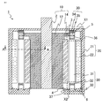
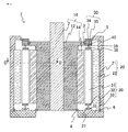
- FIG. 1 is a cross-sectional view taken along a rotation axis showing the structure of the rotary electric machine according to the first embodiment.
- the rotary electric machine 1 includes two rotors, an inner rotor 10, an outer rotor 20, and a stator 30 sandwiched between the two rotors in the radial direction, and is configured as a double rotor type radial gap motor.
- the inner rotor 10 includes a shaft 2, a boss 12 press-fitted and fixed to the shaft 2, and a permanent magnet 14 adhesively fixed to the outer diameter side of the boss 12.
- the outer rotor 20 includes an outer shaft 21 fixed to the shaft 2 and a permanent magnet 22 adhesively fixed to the inner diameter side of the outer shaft 21.
- the stator core 31 is arranged between the load side base holding member 35 attached to the load side stator base 34 and the counterload side stator base 33 in the axial direction, and the stator coil 32 is wound around the stator core 31. There is.
- stator 30 is arranged between the inner rotor 10 and the outer rotor 20, but the inner bearing 3 on the load side, the outer bearing 5 on the load side, the inner bearing 4 on the non-load side, and the outer bearing 6 on the non-load side provide an inner bearing 30.
- the rotor 10 and the outer rotor 20 are rotatably held.
- the stator core 31 has both side portions on the inner rotor 10 side and the outer rotor 20 side extending and protruding in the axial direction at both ends in the axial direction.
- the stator core load side holding portion 36 which is the tip of the stator core 31 on the load side, has a structure bent inward in an L shape
- the stator core anti-load side holding portion 37 which is the tip of the stator core 31 on the counterload side. Has an L-shaped structure that is bent outward.
- the stator core 31 is made of a steel plate, but the stator core load side holding portion 36 and the stator core counterload side holding portion 37 are a part of the stator core 31 and are made of the same steel plate.
- the stator core 31 is configured by laminating thin plates in the rotation direction of the inner rotor 10 and the outer rotor 20, and is stretched in a direction parallel to the surface facing the inner rotor 10 and the outer rotor 20 and perpendicular to the rotation direction.
- the stator core holding portions are provided at both ends.
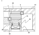
- FIG. 2 is an enlarged view of the region of X1 surrounded by a broken line in FIG. 1
- FIG. 3 is an enlarged view of the region of X2 surrounded by a broken line in FIG. 1, showing the structure of both ends of the stator core 31 in the axial direction. It is shown.
- the stator core load-side holding portion 36 which is a tip portion extended in the load-side direction, which is one of the axial directions of the stator core 31, is bent into an L-shape so as to fit in the axial direction of the stator core 31, and is loaded. It is inserted into the groove of the side base holding member 35.
- the load-side holding surface 38 of the stator core load-side holding portion 36 is in contact with and fixed to the groove portion of the load-side base holding member 35 provided on the load-side stator base 34.
- the stator core anti-load side holding portion 37 which is the tip portion extended in the counter-load side direction which is the other axial direction, has the extended tip portion on the inner rotor 10 side of the inner rotor 10 from the axial direction of the stator core 31.
- the extended tip portion on the outer rotor 20 side is bent into an L shape so as to bend toward the outer rotor 20, and is inserted into the groove portion of the counterload side stator base 33. ..
- the anti-load side holding surface 39 of the stator core anti-load side holding portion 37 is in contact with the groove of the anti-load side stator base 33 and fixed.
- the groove portion of the load side base holding member 35 attached to the load side stator base 34 and the groove portion of the counterload side stator base 33 are partially located in the circumferential direction, respectively, with the stator core load side holding portion 36 and the stator core.
- the counterload side holding portion 37 has an opening large enough to be inserted. After inserting the stator core load side holding portion 36 and the stator core anti-load side holding portion 37 into this opening, the stator core load side holding portion 36 and the stator core anti-load side holding portion 37 are rotated to predetermined positions in the circumferential direction. Is fixed so that it does not come off in the axial direction.
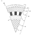
- FIG. 4 is a cross-sectional view perpendicular to the rotation axis of the rotary electric machine 1, and is a partial cross-sectional view in the direction of AA in FIG.
- the rotary electric machine 1 is composed of 48 poles and 72 slots of centralized winding.
- the stator core 31 is formed by laminating thin steel plates long in the axial direction in the substantially circumferential direction.
- the steel plate constituting the stator core 31 is an electromagnetic steel plate manufactured by rolling, and is arranged so that the rolling direction is the radial direction of the stator core.
- Both the inner rotor 10 and the outer rotor 20 rotate counterclockwise in the figure at the same angular velocity. That is, the inner rotor 10 and the outer rotor 20 are movable portions.
- the load-side inner bearing 3 and the non-load-side inner bearing 4 shown in FIG. 1 are angular bearings, and preload the load-side inner bearing 3 and the non-load-side inner bearing 4 in consideration of the axial dimensions of the stator core 31.
- the load side holding surface 38 of the stator core load side holding portion 36 is pressed against the load side stator base 34 (load side base holding member 35), and the counter load side holding surface 39 of the stator core unload side holding portion 37 is countered. It is pressed against the load side stator base 33.
- the stator core 31 is fixed by applying tensile stress in the axial direction on the load side holding surface 38 and the unload side holding surface 39, so that the stator core 31 is fixed by the compressive stress.
- the deterioration of magnetic characteristics is eliminated, and high efficiency can be achieved.
- each end of the stator core 31 on the inner rotor 10 side and the outer rotor 20 side is a flange portion of the stator teeth and is a portion where the stator coil 32 cannot be wound, and this portion is stretched and fixed in the axial direction. Since the holding portion is used, the stator 30 can be fixed without reducing the winding space and without obstructing the magnetic path.
- the stator core load side holding portion 36 which is the tip portion extended in the load side direction on one side in the axial direction, is bent into an L shape so as to fit in the axial width of the stator core 31, and has a limited installation space.
- the stator core 31 can be held.
- the stator core anti-load side holding portion 37 which is the tip end portion extended in the counter-load side direction, which is the other in the axial direction, has an L-shape so as to bend from the axial direction of the stator core 31 toward the inner rotor 10 side and the outer rotor 20 side. Since it is bent, the stator core counterload side holding portion 37 can be largely taken, and the holding strength can be improved.
- stator core load side holding portion 36 and the stator core non-load side holding portion 37 are configured so that the directions in which they are bent into an L shape are different in the radial direction from each other, so that they are difficult to come off in the radial direction. However, it may be configured to be bent in the same direction.
- FIG. 5 is a cross-sectional view taken along the rotation axis of the rotary electric machine 1 according to the second embodiment.
- the stator core 31 has both side portions of the inner rotor 10 and the outer rotor 20 side extending in the axial direction and protruding from the main body portion at both ends in the axial direction.
- the stator core load side holding portion 36 which is the tip portion on the load side, has an obtuse-angled L-shaped structure bent inward, and the stator core counterload, which is the tip portion on the fixed side.
- the side holding portion 37 has an obtuse-angled L-shaped structure that is bent outward. That is, the angles of the L-shape are different.
- the stator core 31 is made of a steel plate, but the stator core load side holding portion 36 and the stator core counterload side holding portion 37 are a part of the stator core 31 and are made of the same steel plate.
- the stator core load side holding portion 36 which is a tip portion extended in the load side direction, which is one of the axial directions, is a groove portion of the load side base holding member 35 attached to the load side stator base 34. Will be inserted into.
- the load-side holding surface 38 of the stator core load-side holding portion 36 is in contact with and fixed to the groove portion of the load-side base holding member 35.
- the stator core anti-load side holding portion 37 which is the tip portion extended in the counter-load side direction, which is the other in the axial direction, has the extended tip portion on the inner rotor 10 side bent from the axial direction of the stator core 31 toward the inner rotor 10.
- the extended tip portion on the outer rotor 20 side is bent into an L shape so as to bend toward the outer rotor 20 side, and is inserted into the groove portion of the counterload side stator base 33.
- the anti-load side holding surface 39 of the stator core anti-load side holding portion 37 is in contact with the anti-load side stator base 33 and fixed.
- the direction in which the load-side holding surface 38 abuts on the load-side base holding member 35 and the direction in which the non-load-side holding surface 39 abuts on the anti-load-side stator base 33 have radial components with each other. , Facing each other in the axial direction.
- stator core load side holding portion 36 and the stator core non-load side holding portion 37 have an obtuse-angled L-shape, the stator core load side holding portion is held with respect to the areas of the load side holding surface 38 and the counterload side holding surface 39.
- the radial dimensions of the portion 36 and the stator core counterload side holding portion 37 are reduced, and the size of the openings of the load side stator base 34 and the counterload side stator base 33 can be reduced, so that the size can be reduced. It will be possible.
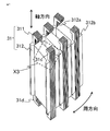
- FIG. 6 is a perspective view showing a part of the structure of the stator 30 of the rotary electric machine according to the third embodiment
- FIG. 7 is a perspective view showing the structure of the stator core 31
- FIG. 8 is a partially enlarged view of the broken line region X3 of FIG. It is a figure.
- the stator core 31 is configured by laminating thin steel plates long in the axial direction in the substantially circumferential direction and the rotational direction.
- both the inner rotor 10 side and the outer rotor 20 side side portions extend axially from the main body portion at both ends thereof in the axial direction, and the tip thereof is projected.
- the portion 31c has a structure bent inward in an L shape on the load side
- the tip portion 31d has a structure bent outward in an L shape on the unloaded side.
- the stator core 31 of the third embodiment is composed of a side portion 311 facing the inner rotor 10 and the outer rotor 20, respectively, and a side portion holding portion 312 that holds both side portions 311 and around which the stator coil 32 is wound. The point that is done is different.
- both side portions 311 of the stator core 31 are configured by laminating thin electromagnetic steel plates that are long in the axial direction in the substantially circumferential direction and the rotational direction.
- the side holding portion 312 of the stator core 31 is configured by laminating an electromagnetic steel sheet having a predetermined shape in the axial direction at a height facing the permanent magnets 14 and 22 of the inner rotor 10 and the outer rotor 20, respectively.
- the side holding portion 312 has a substantially rectangular shape, but a notch portion 312a is provided in the central portion on the inner peripheral side on the inner rotor side and the outer peripheral side on the outer rotor side, and both side portions 311 are inserted. Is retained.
- the flange portion 312b may be provided in the circumferential direction of the notch portion 312a as shown in the figure.
- Both side portions 311 of the stator core 31 are held in close contact with the side portion holding portion 312 so that the magnetic flux in the direction orthogonal to the rotation axis flows seamlessly.
- Both side portions 311 extend from the side holding portion 312 on both sides in the axial direction and have tip portions 31c and 31d bent in an L shape.
- the tip portions 31c and 31d correspond to the stator core load side holding portion 36 and the stator core non-load side holding portion 37 shown in the first and second embodiments, respectively.
- the stator core 31 of the third embodiment which has both side portions 311 laminated in the circumferential direction and the side holding portions 312 laminated in the axial direction, also has an axial tensile stress as in the first and second embodiments. It is hung and held. That is, according to FIG. 1 of the first embodiment, the tip portions 31c and 31d of both side portions of the stator core 31 are fixed, and the counterload side holding surface 39 and the load in the groove portion of the counterload side stator base 33. It is arranged so as to face the load side holding surface 38 in the side base holding member 35.
- FIG. 7 shows a structure in which the axial tip portions 31c and 31d of both side portions 311 are both bent inward so as to face the side holding portion 312 side, as shown in FIGS. 1 and 5. In addition, on the fixed side, the structure may be bent outward.
- stator core 31 of the third embodiment may be bent into an obtuse-angled L-shape as shown in FIG.
- a part of the stator core 31 is formed by laminating thin electromagnetic steel plates long in the axial direction in the substantially circumferential direction and the rotational direction, and the tensile stress is generated. It is a structure that is hung and held, and it is possible to suppress deterioration of magnetic characteristics due to compressive stress and improve efficiency.
- the stator core 31 is configured by laminating thin steel plates long in the axial direction in the substantially circumferential direction and the rotational direction, but in the third embodiment, the side portions 311 are the first and second embodiments.
- a thin steel plate that is long in the axial direction as in 2 is laminated on both the inner peripheral side and the outer peripheral side in the substantially circumferential direction and the rotational direction, and the electromagnetic steel plate is axially connected to the side holding portion 312 that holds both side portions 311. It is composed of laminated layers.
- the direction perpendicular to the axis is a substantially rectangular piece of each electrical steel sheet constituting the side holding portion 312, and it becomes easy to process into a desired shape.
- the side holding portion 312 has a substantially rectangular shape, but the central portion on the inner peripheral side and the outer peripheral side thereof has a notch portion 312a in which both side portions 311 are inserted and held. Is provided, and a flange portion 312b is provided in the circumferential direction of the notch portion 312a. It is also easy to process into such a shape.
- the stator 30 is arranged between the inner rotor 10 and the outer rotor 20, but the stator cores 31 are arranged at regular intervals.
- a magnetic flux is generated due to the non-constant magnetic permeability when viewed from the gap between the inner rotor 10 and the outer rotor 20 and the stator 30.
- the generated magnetic flux is called a spatial harmonic and causes a loss.
- the side holding portion 312 has a flange portion 312b and acts to fill the space between the stators 30 adjacent in the circumferential direction, so that spatial harmonics can be reduced.
- the side holding portions 312 are laminated in the rotation axis direction, the area of the conductor in which the magnetic flux is interlinking is smaller than that in the magnetic flux interlinking in the circumferential direction. This increases the resistance of the conductor and can reduce the eddy current.
- FIG. 9A is a diagram showing side holding portions 312 laminated in the axial direction
- FIG. 9B is a diagram showing both side portions 311 laminated in the circumferential direction.
- the notch 312a of the side holding portion 312 has two types of notches, a notch with a shallow notch 312a1 and a notch with a deep notch 312a2, and the side holding portion 312 has a predetermined thickness d2, respectively. It is laminated so as to be d1.
- the laminated portion of the notch portion 312a1 having a shallow notch is convex on both the inner peripheral side and the outer peripheral side than the laminated portion of the notch portion 312a2 having a deep notch.
- the side portions 311 are arranged so that the inner peripheral side and the outer peripheral side face each other, and on the holding portion side, the protruding portion 311A and the recessed portion 311B have lengths corresponding to the thicknesses d1 and d2, respectively. It is formed sequentially.
- the step d3 between the protruding portion 311A and the recessed portion 311B corresponds to the difference in depth between the notch 312a1 having a shallow notch and the notch 312a2 having a deep notch in the side holding portion 312.
- 9B are a laminated portion and a recessed portion 311B of the notched portion 312a1 having a shallow notch, and a notched portion 312a2 having a deep notch.
- the laminated portion and the protruding portion 311A are fitted so as to match each other, that is, the uneven shapes of both are fitted in the direction of the arrow in the figure to form the stator core 31 as shown in FIG.
- the concave-convex shape formed in the notch 312a of the side holding portion 312 and the concave-convex shape formed in both side portions 311 are fitted to each other, so that the thin plate shapes laminated in different directions from each other are fitted. It is possible to form the stator core 31 in close contact with each other without disassembling the electromagnetic steel sheets.
- the concave-convex shape formed in the notch 312a of the side holding portion 312 and the concave-convex shape formed in both side portions 311 are not limited to the above, and are not limited to, for example, not only fitting in the radial direction but also. It may be shaped so as to fit or engage in the axial direction.
- FIG. 10 is a modified example of FIG. 6 and is a perspective view showing the configuration of another stator 30 according to the third embodiment.
- the difference from FIG. 6 is that in both side portions 311 of the stator core 31, the advancing side portion in the rotation direction in FIG. 4 is a structure 311b made of a non-metal or non-magnetic material, which is not a laminate of electrical steel sheets. ..
- the side delayed in the rotation direction is a laminated body 311a of electrical steel sheets.
- In-plane eddy currents are generated in the electromagnetic steel sheets laminated in the circumferential direction, but the generated eddy currents tend to be larger in the direction of travel in the rotational direction. Therefore, as shown in FIG. 10, by forming the rotation direction advancing side with a member other than the electromagnetic steel sheet, it is possible to suppress the loss due to the eddy current on the rotation direction advancing side.
- a high-strength resin is used as the structure 311b made of a non-metal or non-magnetic material.
- the shapes of the structure 311b and the laminated body 311a of the electrical steel sheets are not limited to the drawings, and the sizes in the circumferential direction of the two may be different.
- both side portions 311 constituting the stator core 31 are formed by laminating thin electromagnetic steel plates long in the axial direction in the substantially circumferential direction and the rotational direction, and tensile stress is applied. Since the configuration is as follows, deterioration of magnetic characteristics due to compressive stress can be suppressed and high efficiency can be achieved as in the first and second embodiments. Further, the side holding portion 312 of the stator core that holds both side portions 311 is configured by laminating substantially square electromagnetic steel sheets in the axial direction, and the inner peripheral side and the outer peripheral side are formed into a collar shape to form spatial harmonics. It also contributes to the suppression of eddy currents and makes it possible to improve efficiency.
- both side portions 311 constituting the stator core 31 is a structure 311b made of a non-metal or non-magnetic material which is not a laminated material of electrical steel sheets, it is possible to reduce the loss due to eddy current. Will be.
- FIG. 11 is a cross-sectional view taken along the rotation axis of the rotary electric machine 1 according to the fourth embodiment.
- the difference from the first embodiment is that the stator core 31 has a width narrower than the width facing the inner rotor 10 and the outer rotor 20 of the stator core 31 from the radial center portion at both ends in the axial direction. It extends in the direction and protrudes.
- the stator core load-side holding portion 36 which is a protruding tip on the load side
- the stator core anti-load-side holding portion 37 which is a protruding tip on the fixed side
- the connecting portion between the portion extending in the axial direction and the portion extending in the radial direction has a tapered shape.
- the stator core 31 is made of an electromagnetic steel plate, but the stator core load side holding portion 36 and the stator core non-load side holding portion 37 are a part of the stator core 31 and are made of the same steel plate.
- the stator core load-side holding portion 36 which is a tip portion extended in the load-side direction, which is one of the axial directions, is a load-side base holding member 35 attached to the load-side stator base 34. It is inserted into the groove of.
- the load-side holding surface 38 which is a radial portion of the stator core load-side holding portion 36 having a T-shaped structure, is in contact with and fixed to the groove portion of the load-side base holding member 35.
- the stator core counterload side holding portion 37 which is the tip portion extended in the counterload side direction, which is the other in the axial direction, is inserted into the groove portion of the counterload side stator base 33.
- the anti-load side holding surface 39 which is a radial portion of the stator core anti-load side holding portion 37 having a T-shaped structure, is in contact with the anti-load side stator base 33 and fixed.
- the direction in which the stator core 31 abuts on the load-side base holding member 35 of the load-side holding surface 38 and the direction in which the counter-load-side holding surface 39 abuts on the anti-load-side stator base 33 have diameters of each other. Although they have directional components, they face each other in the axial direction.
- stator core load side holding portion 36 and the stator core non-load side holding portion 37 have a T-shape
- stator core load side holding portion 36 and the stator core load side holding portion 36 and the stator core load side holding portion 36 and the stator core load side holding portion 36 and the stator core load side holding portion 36 and the stator core load side holding portion 36 have a T-shape with respect to the areas of the load side holding surface 38 and the counter load side holding surface 39.
- stator core counterload side holding portion 37 Since the radial dimension of the stator core counterload side holding portion 37 is small, the size of the opening of the load side base holding member 35 attached to the load side stator base 34 and the opening of the counterload side stator base 33 should be adjusted. It can be made smaller. Further, since the stator core load side holding portion 36 and the stator core non-load side holding portion 37 are each located at one position in the axial direction, the number of holding portions can be reduced and the size can be reduced. Further, the stator core load side holding portion 36 and the stator core non-load side holding portion 37 have a T-shaped structure, and the connecting portion between the axially extending portion and the radially extending portion has a tapered shape. The connection part can secure a certain strength.
- FIG. 12 is a cross-sectional view taken along the rotation axis of the rotary electric machine 1 according to the fifth embodiment.
- the stator core 31 differs from the first embodiment in that the width of the stator core 31 is narrower than the width facing the inner rotor 10 and the outer rotor 20 of the stator core 31 from the radial center portion at both ends in the axial direction. It extends in the direction and protrudes. Further, the difference from the third embodiment is that an engaging hole is provided in each of the tip portions extending in the axial direction and protruding.
- the stator core 31 is made of an electromagnetic steel plate, but the stator core load side holding portion 36 and the stator core non-load side holding portion 37 are a part of the stator core 31 and are made of the same steel plate.
- FIG. 13 is an enlarged view of the region of X4 surrounded by a broken line in FIG. 12
- FIG. 14 is an enlarged view of the region of X5 surrounded by a broken line in FIG. 12, showing the structure of both ends of the stator core 31 in the axial direction. It is shown.
- the hole 36a provided in the stator core load-side holding portion 36 which is the tip end portion extended in the load-side direction, which is one of the axial directions, is inserted into the fixing pin 40 attached to the load-side base holding member 35.
- the load-side holding surface 38 is fixed to the load-side stator base 34 so as to abut on the fixing pin 40 of the load-side base holding member 35.
- the counterload side holding surface 39 is fixed to the counterload side stator base 33 so as to abut on the fixing pin 40 of the counterload side stator base 33.
- the direction in which the load-side holding surface 38 abuts on the load-side base holding member 35 and the direction in which the non-load-side holding surface 39 abuts on the anti-load-side stator base 33 are radial components of each other. However, they face each other in the axial direction.
- stator core load side holding portion 36 and the stator core anti-load side holding portion 37 are structured to be engaged with the fixing pin 40, and the stator core load side holding portion is held by the anti-load side stator base 33 and the load side stator base 34. Since an opening for inserting the portion 36 and the stator core counterload side holding portion 37 is not required, miniaturization is possible. Further, as in the fourth embodiment, since the stator core load side holding portion 36 and the stator core non-load side holding portion 37 are each located at one position in the axial direction, the number of holding portions can be reduced, and the size can be reduced in this respect as well. Is possible.
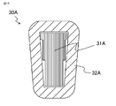
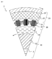
- FIG. 15 is a cross-sectional view along a rotation axis showing the structure of the rotary electric machine 1A according to the sixth embodiment
- FIG. 16 is a cross-sectional view showing the structure of the stator 30A, which is a part in the direction of BB in FIG. It is a cross-sectional view.
- the rotary electric machine 1A includes two rotors, a counterload side rotor 10A and a load side rotor 20A, and a stator 30A sandwiched between the two rotors in the radial direction, and is configured as a double rotor type axial gap motor. Has been done.
- the counterload side rotor 10A includes a shaft 2A, a counterload side boss 12A press-fitted and fixed to the shaft 2A, and a permanent magnet 14A adhesively fixed to the load side of the counterload side boss 12A.
- the load-side rotor 20A includes a load-side boss 21A fixed to the shaft 2A and a permanent magnet 22A adhesively fixed to the non-load-side of the load-side boss 21A.
- the stator 30A is arranged between the counterload side rotor 10A and the load side rotor 20A, and the load side inner bearing 3A and the counterload side inner bearing 4A rotatably hold the counterload side rotor 10A and the load side rotor 20A, respectively. ing.
- the stator core 31A is arranged between the outer diameter side holding member 35A and the inner diameter side holding member 33A in the radial direction, and the stator coil 32A is wound around the stator core 31A.
- outer diameter side holding member 35A is attached to the counterload side base 41A and the load side base 41B arranged apart from the shaft 2A, and is two rotors, the counterload side rotor 10A and the load side rotor 20A. Surrounding.
- the shaft 2A protrudes from the central portion of the load side base 41B so as to be rotatable, and is separated from the load side base 41B.
- stator core 31A thin steel plates long in the radial direction are laminated in the substantially circumferential direction, that is, in the rotational direction. At both ends of the stator core 31A in the radial direction, both sides of the reverse load side rotor 10A side and the load side rotor 20A side in the radial direction extend and project.
- the outer diameter side holding portion 36A of the stator core has an L-shaped tip portion bent outward in the axial direction, that is, both sides are separated from each other, and has an outer diameter.
- the L-shaped portion is engaged with the groove portion 35Aa of the side holding member 35A, and the outer diameter side holding surface 38A of the outer diameter side stator core outer diameter side holding portion 36A is in contact with the groove portion 35Aa and fixed.
- the inner diameter side holding portion 37A of the stator core has an L-shaped tip portion bent inward in the axial direction, that is, so that both sides face each other, and has an inner diameter side holding member. It is engaged with the L-shaped groove portion 33Ab provided in the 33A, and the inner diameter side holding surface 39A of the stator core inner diameter side holding portion 37A is in contact with the groove portion 33Ab and fixed.
- stator core 31A In the stator core 31A, the direction in which the outer diameter side holding surface 38A abuts on the groove portion 35Aa of the outer diameter side holding member 35A and the direction in which the inner diameter side holding surface 39A abuts on the groove portion 33Ab provided in the inner diameter side holding member 33A are mutual. They face each other in the radial direction. That is, the stator core 31A is fixed by applying tensile stress.
- stator core 31A is fixed by applying tensile stress, the same effect as that of the first embodiment is obtained. That is, it can be configured without deterioration of magnetic characteristics due to compressive stress, torque is improved, and it is possible to provide a highly efficient rotary electric machine.
- the rotary electric machine 1A is configured as a centralized winding of 10 poles and 12 slots.
- the stator core 31A is formed by laminating thin steel plates long in the radial direction in the substantially circumferential direction. Both the non-load side rotor 10A and the load side rotor 20A rotate at the same angular velocity.
- the thin steel plate of the stator core 31A is an electromagnetic steel plate manufactured by rolling, and the rolling direction is arranged so as to be the axial direction of the stator core 31A, that is, the direction in which the counterload side rotor 10A and the load side rotor 20A face each other. Has been done.
- FIG. 17 is a cross-sectional view along a rotation axis showing the structure of the magnetic gear 1B according to the seventh embodiment
- FIG. 18 is a partial cross-sectional view in the direction of CC in FIG.
- the magnetic gear 1B does not include the stator coil 32.
- the stator core 31 is flat and does not have bent portions (flange portions) on both sides in the radial direction.
- the stator core 31 acts as a pole piece that modulates the magnetic flux of the inner rotor 10 and the outer rotor 20 with respect to the inner rotor 10 and the outer rotor 20 depending on the magnitude of the magnetic resistance depending on the presence or absence of the stator core 31 in the circumferential direction.
- the inner rotor 10 and the outer rotor 20 of the magnetic gear 1B are not connected to each other.
- the inner rotor 10 rotates counterclockwise in the figure
- the outer rotor 20 rotates clockwise in the figure at the same electric angular velocity as the inner rotor 10.
- the number of poles of the outer rotor 20 is 60
- the number of poles of the inner rotor 10 is 12, and the number of poles of the outer rotor 20 is 5 times the number of poles of the inner rotor 10
- a magnetic gear having a reduction ratio of 5 is configured. can do.
- the stator core 31 extends and protrudes in the axial direction from the radial center portion at both ends thereof in the axial direction.
- the stator core load side holding portion 36 which is the tip end portion extended in the load side direction on one side in the axial direction, is provided with an engaging hole, and the load provided on the load side stator base 34. It is inserted into the fixing pin 40 of the side base holding member 35, and the load side holding surface 38 is in contact with and fixed to the fixing pin 40 of the load side base holding member 35.
- the stator core counterload side holding portion 37 which is the tip portion extended in the counterload side direction, which is the other in the axial direction, has a T-shaped structure as in the third embodiment, and has a counterload side stator base.
- the anti-load side holding surface 39 which is a radial portion of the stator core anti-load side holding portion 37 having a T-shaped structure, is in contact with the anti-load side stator base 33 and fixed.
- the stator core 31 is made of an electromagnetic steel plate, but the stator core load side holding portion 36 and the stator core non-load side holding portion 37 are a part of the stator core 31 and are made of the same steel plate. Other configurations are the same as those in the first embodiment.
- the direction in which the load-side holding surface 38 abuts on the load-side base holding member 35 and the direction in which the non-load-side holding surface 39 abuts on the non-load-side stator base 33 are mutually different. It has radial components but is axially opposed to each other. That is, the stator core 31 is fixed by applying tensile stress.
- the same effect as that of the first embodiment is obtained in the configuration of the magnetic gear according to the seventh embodiment. That is, in the magnetic gear 1B, since the stator core 31 is stretched in the axial direction and fixed in a state where tensile stress is applied, it is possible to hold the stator core 31 without deteriorating the magnetic characteristics. This makes it possible to increase the efficiency and torque of the magnetic gear. Further, since the stator core load side holding portion 36 and the stator core non-load side holding portion 37 are each located at one position in the axial direction, the number of holding portions can be reduced and the size can be reduced. Also in other embodiments, the holding structures of the stator core load side holding portion 36 and the stator core non-load side holding portion 37 may be different as in the present embodiment.
- the rotation directions of the inner rotor 10 and the outer rotor 20 are the same, but they may be in opposite directions.
- the number of stator cores 31, which are pole pieces may be 72 instead of 48.
- the number of poles of the inner rotor 10 and the outer rotor 20 may be set as magnetic gears according to the gear ratio of the object driven by the inner rotor 10 and the outer rotor 20.
- FIG. 19 is a cross-sectional view taken along a rotation axis showing the structure of the rotary electric machine 1 according to the eighth embodiment.
- the difference from the first embodiment is that the outer shaft 21 is not fixed to the shaft 2. Further, it corresponds to a magnetic geared motor in which the stator coil 32 is wound around the magnetic gear of the seventh embodiment. Therefore, the inner rotor 10 and the outer rotor 20 of the rotary electric machine 1 are not connected to each other. For example, the inner rotor 10 and the outer rotor 20 rotate in opposite directions, and the outer rotor 20 is divided into two parts of the inner rotor 10. Rotate at an angular velocity of 1.
- FIG. 20 is a cross-sectional view perpendicular to the rotation axis of the rotary electric machine 1, and is a partial cross-sectional view in the direction of the DD line in FIG.
- the stator core 31 is configured by laminating thin electromagnetic steel plates that are long in the axial direction in the substantially circumferential direction, but each side facing the inner rotor 10 and the outer rotor 20 side, which are both sides of the stator core 31 in the axial direction.
- the portion does not have a bent portion (flange portion).
- stator core 31 of the eighth embodiment is also attached under tensile stress.
- the inner rotor 10 and the outer rotor 20 rotate in opposite directions, and the outer rotor 20 has an angular velocity that is half that of the inner rotor 10, but the inner rotor 10 and the outer rotor 20 have different angular velocities.
- the rotation directions may be the same, or the rotation speeds of both may be set independently.
- the stator 30 is arranged between the inner rotor 10 and the outer rotor 20 that are movable around the shaft 2, and the stator 30 has a stator core 31 in which thin plates are laminated in the rotational direction, and exerts tensile stress in the axial direction. Since it is hung and held, it is possible to hold the stator core 31 without deteriorating the magnetic characteristics. This makes it possible to increase the efficiency and torque of the rotary electric machine.
- the rotation direction and the rotation speed of each can be set independently, so that even if the object to be driven by each rotor is different, It is possible to set and control the rotation direction and rotation speed, respectively.
- FIG. 21 is a diagram showing an example of the aircraft 100 according to the ninth embodiment, and is equipped with the rotary electric machine described in the first to eighth embodiments.
- a fan 230, a rotary electric machine 1, 1A, a magnetic gear 1B, and an engine 220 are arranged in an engine case 210 of an aircraft 100 by being connected by a shaft.
- the rotary electric machines 1 and 1A are motors and are used to drive the fan 230, and the magnetic gear 1B is used as a transmission for accelerating and decelerating.
- the rotation speed is between the fan 230 and the rotary electric machines 1, 1A, or between the rotary electric machines 1, 1A and the engine 220, or both. It may be equipped with a gear that changes.
- the gear may be a mechanical gear such as a spur gear or a planetary gear, but a magnetic gear 1B may be mounted.
- the rotary electric machines 1 and 1A are mounted, in FIG. 16, the rotary electric machines 1 and 1A and the engine 220 are arranged coaxially with respect to the fan 230, but even if they are configured on different axes via gears or the like. It has the same effect.
- tensile stress is applied to the stator core, so that the stator core can be reliably held without deteriorating the magnetic characteristics and a high torque output can be obtained. Therefore, it is suitable for application to a rotating object mounted on an aircraft. Further, since the magnetic gear shown in the seventh embodiment surely holds the stator core without deteriorating the magnetic characteristics and has no wear points as compared with the mechanical gear, it can be used as a mechanical component mounted on an aircraft. Is suitable for application.
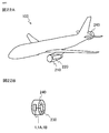
- FIG. 22 is a diagram showing another example of the aircraft 100 according to the ninth embodiment
- FIG. 22A is a schematic enlarged view of the aircraft 100 having a fan case 240 at the tail
- FIG. 22B is a schematic enlarged view of the fan case 240.
- the rotary electric machine described in the first to eighth embodiments is similarly mounted.
- the rotary electric machine is housed in the same engine case 210 as the engine 220, but as shown in FIG. 22, it may be housed in a case different from the engine 220 to drive the driven object.
- FIG. 22 shows an example in which the rotary electric machines 1 and 1A or the magnetic gear 1B are connected to the fan 230 by a shaft in the fan case 240 at the tail. When the magnetic gear 1B is connected, the rotary electric machines 1, 1A or the engine 220 are further connected and driven.
- the aircraft 100 does not have an engine 220 and may be equipped with rotary electric machines 1 and 1A as a drive power source. Further, although not shown, it may be attached to a wing such as a helicopter or a multicopter having a plurality of rotary wings instead of the fixed-wing aircraft 100 and used as a drive source.
- a wing such as a helicopter or a multicopter having a plurality of rotary wings instead of the fixed-wing aircraft 100 and used as a drive source.
- the stator core is surely held without deteriorating the magnetic characteristics and a high torque output is obtained. Since it can be obtained, the cruising range per fuel can be improved.
- the load-side stator base 34 and the non-load-side stator base 33 may be made of a magnetic material such as iron, but it is preferably made of a material having a low magnetic permeability or a non-magnetic material. By doing so, the magnetic flux passing between the stator cores 31 in the circumferential direction via the load-side stator base 34 and the non-load-side stator base 33 can be reduced or eliminated, so that the torque can be improved and the size can be reduced. It can be made lighter.
- the rotary electric machines 1 and 1A are motors, but the same effect can be obtained even if they operate as a generator.
Landscapes
- Engineering & Computer Science (AREA)
- Power Engineering (AREA)
- Aviation & Aerospace Engineering (AREA)
- Chemical & Material Sciences (AREA)
- Combustion & Propulsion (AREA)
- Iron Core Of Rotating Electric Machines (AREA)
- Permanent Magnet Type Synchronous Machine (AREA)
Priority Applications (4)
| Application Number | Priority Date | Filing Date | Title |
|---|---|---|---|
| US17/917,257 US12191723B2 (en) | 2020-05-29 | 2021-01-21 | Rotary electric machine having a stator core formed with stacked thin sheets and aircraft using the rotary electric machine core |
| DE112021003038.8T DE112021003038T5 (de) | 2020-05-29 | 2021-01-21 | Rotierende elektrische maschine und luftfahrzeug, das die rotierende elektrische maschine verwendet |
| CN202180037308.1A CN115715450A (zh) | 2020-05-29 | 2021-01-21 | 旋转电机以及使用旋转电机的飞机 |
| JP2022527495A JP7361915B2 (ja) | 2020-05-29 | 2021-01-21 | 回転電機及び回転電機を用いた航空機 |
Applications Claiming Priority (2)
| Application Number | Priority Date | Filing Date | Title |
|---|---|---|---|
| JP2020-094052 | 2020-05-29 | ||
| JP2020094052 | 2020-05-29 |
Publications (1)
| Publication Number | Publication Date |
|---|---|
| WO2021240871A1 true WO2021240871A1 (ja) | 2021-12-02 |
Family
ID=78744215
Family Applications (1)
| Application Number | Title | Priority Date | Filing Date |
|---|---|---|---|
| PCT/JP2021/002030 Ceased WO2021240871A1 (ja) | 2020-05-29 | 2021-01-21 | 回転電機及び回転電機を用いた航空機 |
Country Status (5)
| Country | Link |
|---|---|
| US (1) | US12191723B2 (https=) |
| JP (1) | JP7361915B2 (https=) |
| CN (1) | CN115715450A (https=) |
| DE (1) | DE112021003038T5 (https=) |
| WO (1) | WO2021240871A1 (https=) |
Cited By (2)
| Publication number | Priority date | Publication date | Assignee | Title |
|---|---|---|---|---|
| US20230006485A1 (en) * | 2019-12-04 | 2023-01-05 | Schaeffler Technologies AG & Co. KG | Axial flux machine comprising mechanically fixed stator cores having radially extending sheet metal segments |
| EP4415232A1 (en) * | 2023-02-09 | 2024-08-14 | Koenigsegg Automotive AB | Radially or axially enhanced electric motor |
Families Citing this family (1)
| Publication number | Priority date | Publication date | Assignee | Title |
|---|---|---|---|---|
| CN115917926A (zh) * | 2020-05-29 | 2023-04-04 | 三菱电机株式会社 | 电磁设备以及使用电磁设备的飞机 |
Citations (3)
| Publication number | Priority date | Publication date | Assignee | Title |
|---|---|---|---|---|
| JP2006025484A (ja) * | 2004-07-06 | 2006-01-26 | Nissan Motor Co Ltd | ラジアル回転電機のステータ構造 |
| JP2010178599A (ja) * | 2009-02-02 | 2010-08-12 | Mazda Motor Corp | 回転電機 |
| JP2012120262A (ja) * | 2010-11-29 | 2012-06-21 | Aisin Seiki Co Ltd | 電動機のステータコアの取付構造 |
Family Cites Families (6)
| Publication number | Priority date | Publication date | Assignee | Title |
|---|---|---|---|---|
| US5396140A (en) * | 1993-05-28 | 1995-03-07 | Satcon Technology, Corp. | Parallel air gap serial flux A.C. electrical machine |
| JP2006174637A (ja) * | 2004-12-17 | 2006-06-29 | Nissan Motor Co Ltd | 回転電機のステータ製造方法 |
| JP6801396B2 (ja) | 2016-11-25 | 2020-12-16 | トヨタ自動車株式会社 | 二重ロータ構造のモータ |
| JP2019037084A (ja) | 2017-08-18 | 2019-03-07 | トヨタ自動車株式会社 | ダブルロータ型の三相回転電機 |
| EP3672025A1 (en) * | 2018-12-17 | 2020-06-24 | Siemens Gamesa Renewable Energy A/S | Electric machine and wind turbine |
| CN115917926A (zh) * | 2020-05-29 | 2023-04-04 | 三菱电机株式会社 | 电磁设备以及使用电磁设备的飞机 |
-
2021
- 2021-01-21 CN CN202180037308.1A patent/CN115715450A/zh not_active Withdrawn
- 2021-01-21 US US17/917,257 patent/US12191723B2/en active Active
- 2021-01-21 DE DE112021003038.8T patent/DE112021003038T5/de not_active Withdrawn
- 2021-01-21 JP JP2022527495A patent/JP7361915B2/ja active Active
- 2021-01-21 WO PCT/JP2021/002030 patent/WO2021240871A1/ja not_active Ceased
Patent Citations (3)
| Publication number | Priority date | Publication date | Assignee | Title |
|---|---|---|---|---|
| JP2006025484A (ja) * | 2004-07-06 | 2006-01-26 | Nissan Motor Co Ltd | ラジアル回転電機のステータ構造 |
| JP2010178599A (ja) * | 2009-02-02 | 2010-08-12 | Mazda Motor Corp | 回転電機 |
| JP2012120262A (ja) * | 2010-11-29 | 2012-06-21 | Aisin Seiki Co Ltd | 電動機のステータコアの取付構造 |
Cited By (4)
| Publication number | Priority date | Publication date | Assignee | Title |
|---|---|---|---|---|
| US20230006485A1 (en) * | 2019-12-04 | 2023-01-05 | Schaeffler Technologies AG & Co. KG | Axial flux machine comprising mechanically fixed stator cores having radially extending sheet metal segments |
| US12316165B2 (en) * | 2019-12-04 | 2025-05-27 | Schaeffler Technologies AG & Co. KG | Axial flux machine comprising mechanically fixed stator cores having radially extending sheet metal segments |
| EP4415232A1 (en) * | 2023-02-09 | 2024-08-14 | Koenigsegg Automotive AB | Radially or axially enhanced electric motor |
| WO2024165728A1 (en) * | 2023-02-09 | 2024-08-15 | Koenigsegg Automotive Ab | Radially or axially enhanced electric motor |
Also Published As
| Publication number | Publication date |
|---|---|
| US12191723B2 (en) | 2025-01-07 |
| JPWO2021240871A1 (https=) | 2021-12-02 |
| JP7361915B2 (ja) | 2023-10-16 |
| CN115715450A (zh) | 2023-02-24 |
| DE112021003038T5 (de) | 2023-03-16 |
| US20230163669A1 (en) | 2023-05-25 |
Similar Documents
| Publication | Publication Date | Title |
|---|---|---|
| US7804216B2 (en) | Permanent-magnet reluctance electrical rotary machine | |
| US9071118B2 (en) | Axial motor | |
| EP3611403B1 (en) | Jam-tolerant electric linear actuator | |
| JP7361915B2 (ja) | 回転電機及び回転電機を用いた航空機 | |
| WO2011114594A1 (ja) | 永久磁石形回転電機 | |
| JP6649238B2 (ja) | 回転電機およびロボット装置 | |
| JP2008271640A (ja) | アキシャルギャップ型モータ | |
| WO2011125308A1 (ja) | 永久磁石形回転電機の回転子 | |
| JP2014180094A (ja) | 永久磁石回転電機およびエレベーター駆動巻上機 | |
| JP2017169343A (ja) | 回転電機、巻上機、およびエレベータ | |
| JP2018164378A (ja) | Ipmロータ用磁石、ipmロータおよびipmロータ用磁石の製造方法 | |
| US20200036245A1 (en) | Rotary electric machine and vehicle carrying rotary electric machine | |
| JP4369384B2 (ja) | 回転電機 | |
| JP7361914B2 (ja) | 電磁機器及び電磁機器を用いた航空機 | |
| WO2023199460A1 (ja) | 回転装置 | |
| EP1835600A2 (en) | Motor/generator | |
| WO2021131298A1 (ja) | 回転電機 | |
| JP2014082834A (ja) | ロータと、それを備える回転電機 | |
| JP7124247B1 (ja) | 回転電機の回転子 | |
| JP2014082836A (ja) | ロータと、それを備える回転電機 | |
| JP5609514B2 (ja) | リングコイルモータ | |
| US20240063671A1 (en) | Rotor | |
| CN216489955U (zh) | 一种航空高速电机转子 | |
| EP4329152A1 (en) | Rotor | |
| JP2024157473A (ja) | 永久磁石式電動機 |
Legal Events
| Date | Code | Title | Description |
|---|---|---|---|
| 121 | Ep: the epo has been informed by wipo that ep was designated in this application |
Ref document number: 21812920 Country of ref document: EP Kind code of ref document: A1 |
|
| ENP | Entry into the national phase |
Ref document number: 2022527495 Country of ref document: JP Kind code of ref document: A |
|
| 122 | Ep: pct application non-entry in european phase |
Ref document number: 21812920 Country of ref document: EP Kind code of ref document: A1 |