WO2021240794A1 - ロック機構 - Google Patents
ロック機構 Download PDFInfo
- Publication number
- WO2021240794A1 WO2021240794A1 PCT/JP2020/021371 JP2020021371W WO2021240794A1 WO 2021240794 A1 WO2021240794 A1 WO 2021240794A1 JP 2020021371 W JP2020021371 W JP 2020021371W WO 2021240794 A1 WO2021240794 A1 WO 2021240794A1
- Authority
- WO
- WIPO (PCT)
- Prior art keywords
- hook
- door
- opening
- housing
- shaft
- Prior art date
- Legal status (The legal status is an assumption and is not a legal conclusion. Google has not performed a legal analysis and makes no representation as to the accuracy of the status listed.)
- Ceased
Links
Images






Classifications
-
- E—FIXED CONSTRUCTIONS
- E05—LOCKS; KEYS; WINDOW OR DOOR FITTINGS; SAFES
- E05C—BOLTS OR FASTENING DEVICES FOR WINGS, SPECIALLY FOR DOORS OR WINDOWS
- E05C9/00—Arrangements of simultaneously actuated bolts or other securing devices at well-separated positions on the same wing
- E05C9/04—Arrangements of simultaneously actuated bolts or other securing devices at well-separated positions on the same wing with two sliding bars moved in opposite directions when fastening or unfastening
-
- E—FIXED CONSTRUCTIONS
- E05—LOCKS; KEYS; WINDOW OR DOOR FITTINGS; SAFES
- E05C—BOLTS OR FASTENING DEVICES FOR WINGS, SPECIALLY FOR DOORS OR WINDOWS
- E05C3/00—Fastening devices with bolts moving pivotally or rotatively
- E05C3/02—Fastening devices with bolts moving pivotally or rotatively without latching action
- E05C3/06—Fastening devices with bolts moving pivotally or rotatively without latching action with operating handle or equivalent member moving otherwise than rigidly with the bolt
-
- E—FIXED CONSTRUCTIONS
- E05—LOCKS; KEYS; WINDOW OR DOOR FITTINGS; SAFES
- E05B—LOCKS; ACCESSORIES THEREFOR; HANDCUFFS
- E05B17/00—Accessories in connection with locks
- E05B17/20—Means independent of the locking mechanism for preventing unauthorised opening, e.g. for securing the bolt in the fastening position
- E05B17/2084—Means to prevent forced opening by attack, tampering or jimmying
- E05B17/2088—Means to prevent disengagement of lock and keeper
-
- E—FIXED CONSTRUCTIONS
- E05—LOCKS; KEYS; WINDOW OR DOOR FITTINGS; SAFES
- E05B—LOCKS; ACCESSORIES THEREFOR; HANDCUFFS
- E05B63/00—Locks or fastenings with special structural characteristics
- E05B63/24—Arrangements in which the fastening members which engage one another are mounted respectively on the wing and the frame and are both movable, e.g. for release by moving either of them
-
- E—FIXED CONSTRUCTIONS
- E05—LOCKS; KEYS; WINDOW OR DOOR FITTINGS; SAFES
- E05B—LOCKS; ACCESSORIES THEREFOR; HANDCUFFS
- E05B63/00—Locks or fastenings with special structural characteristics
- E05B63/24—Arrangements in which the fastening members which engage one another are mounted respectively on the wing and the frame and are both movable, e.g. for release by moving either of them
- E05B63/242—Auxiliary bolts on the frame, actuated by bolts on the wing, or vice versa
-
- E—FIXED CONSTRUCTIONS
- E05—LOCKS; KEYS; WINDOW OR DOOR FITTINGS; SAFES
- E05C—BOLTS OR FASTENING DEVICES FOR WINGS, SPECIALLY FOR DOORS OR WINDOWS
- E05C3/00—Fastening devices with bolts moving pivotally or rotatively
- E05C3/006—Fastening devices with bolts moving pivotally or rotatively about an axis parallel to the surface on which the fastener is mounted
- E05C3/008—Fastening devices with bolts moving pivotally or rotatively about an axis parallel to the surface on which the fastener is mounted parallel to the wing edge
-
- E—FIXED CONSTRUCTIONS
- E05—LOCKS; KEYS; WINDOW OR DOOR FITTINGS; SAFES
- E05C—BOLTS OR FASTENING DEVICES FOR WINGS, SPECIALLY FOR DOORS OR WINDOWS
- E05C3/00—Fastening devices with bolts moving pivotally or rotatively
- E05C3/02—Fastening devices with bolts moving pivotally or rotatively without latching action
- E05C3/04—Fastening devices with bolts moving pivotally or rotatively without latching action with operating handle or equivalent member rigid with the bolt
- E05C3/041—Fastening devices with bolts moving pivotally or rotatively without latching action with operating handle or equivalent member rigid with the bolt rotating about an axis perpendicular to the surface on which the fastener is mounted
- E05C3/042—Fastening devices with bolts moving pivotally or rotatively without latching action with operating handle or equivalent member rigid with the bolt rotating about an axis perpendicular to the surface on which the fastener is mounted the handle being at one side, the bolt at the other side or inside the wing
-
- E—FIXED CONSTRUCTIONS
- E06—DOORS, WINDOWS, SHUTTERS, OR ROLLER BLINDS IN GENERAL; LADDERS
- E06B—FIXED OR MOVABLE CLOSURES FOR OPENINGS IN BUILDINGS, VEHICLES, FENCES OR LIKE ENCLOSURES IN GENERAL, e.g. DOORS, WINDOWS, BLINDS, GATES
- E06B5/00—Doors, windows, or like closures for special purposes; Border constructions therefor
- E06B5/10—Doors, windows, or like closures for special purposes; Border constructions therefor for protection against air-raid or other war-like action; for other protective purposes
- E06B5/12—Doors, windows, or like closures for special purposes; Border constructions therefor for protection against air-raid or other war-like action; for other protective purposes against air pressure, explosion, or gas
-
- E—FIXED CONSTRUCTIONS
- E05—LOCKS; KEYS; WINDOW OR DOOR FITTINGS; SAFES
- E05B—LOCKS; ACCESSORIES THEREFOR; HANDCUFFS
- E05B15/00—Other details of locks; Parts for engagement by bolts of fastening devices
- E05B15/02—Striking-plates; Keepers; Bolt staples; Escutcheons
- E05B15/0205—Striking-plates, keepers, staples
- E05B2015/023—Keeper shape
- E05B2015/0235—Stud-like
-
- E—FIXED CONSTRUCTIONS
- E05—LOCKS; KEYS; WINDOW OR DOOR FITTINGS; SAFES
- E05C—BOLTS OR FASTENING DEVICES FOR WINGS, SPECIALLY FOR DOORS OR WINDOWS
- E05C9/00—Arrangements of simultaneously actuated bolts or other securing devices at well-separated positions on the same wing
- E05C9/18—Details of fastening means or of fixed retaining means for the ends of bars
- E05C9/1825—Fastening means
- E05C9/1833—Fastening means performing sliding movements
- E05C9/185—Fastening means performing sliding movements parallel with actuating bar
- E05C2009/1866—Fastening means performing sliding movements parallel with actuating bar of the keyhole slot type
-
- E—FIXED CONSTRUCTIONS
- E05—LOCKS; KEYS; WINDOW OR DOOR FITTINGS; SAFES
- E05C—BOLTS OR FASTENING DEVICES FOR WINGS, SPECIALLY FOR DOORS OR WINDOWS
- E05C9/00—Arrangements of simultaneously actuated bolts or other securing devices at well-separated positions on the same wing
- E05C9/04—Arrangements of simultaneously actuated bolts or other securing devices at well-separated positions on the same wing with two sliding bars moved in opposite directions when fastening or unfastening
- E05C9/048—Arrangements of simultaneously actuated bolts or other securing devices at well-separated positions on the same wing with two sliding bars moved in opposite directions when fastening or unfastening externally mounted on the wing, i.e. surface mounted
Definitions
- An embodiment of the present invention relates to a locking mechanism.
- a control panel in which a circuit such as a power conversion system is housed has a box-shaped housing having an opening and a door that closes the opening of the housing.
- a circuit such as a power conversion system
- the door and the housing are engaged and the closed state of the door is maintained.
- the locking mechanism includes, for example, a hook that rotates around the axis of rotation, an engaging portion that engages with the hook, and a spring that maintains the engaged or disengaged state of the hook with the engaged portion.
- the lock mechanism as described above has a complicated structure and may be costly. If a lock mechanism is provided separately from the handle, the lock mechanism is engaged and disengaged in addition to the opening and closing work of the handle. For this reason, the opening and closing work of the door may become troublesome in the end.
- the problem to be solved by the present invention is to provide a lock mechanism capable of simplifying the structure while satisfying the explosion-proof function and also simplifying the opening and closing work of the door.
- the locking mechanism of the embodiment includes an engaging portion, a hook, and a pressing portion.
- the engaging portion is provided on either the housing or the door that opens and closes the housing opening of the housing.
- the hook is rotatably provided on either the housing or the door around the rotation axis, is engageable with the engaging portion, and is always disengaged from the engaging portion by its own weight.
- the pressing portion is provided separately from the hook and presses the hook.
- the hook has a hook side engaging portion that is engaged with the engaging portion across the rotation axis, and a hook side that engages the engaging portion and the hook side engaging portion by being pressed by the pressing portion. It has a pressing portion and.
- a view of arrow 5 in FIG. The operation explanatory drawing which shows the lock mechanism of 1st Embodiment.
- the operation explanatory drawing which shows the lock mechanism of 1st Embodiment. which shows the lock mechanism of 1st Embodiment.
- the schematic block diagram which shows the hook of the 1st modification in embodiment The schematic block diagram which shows the control panel of 2nd Embodiment. B arrow view of FIG.
- the operation explanatory drawing which shows the lock mechanism of 2nd Embodiment The operation explanatory drawing which shows the lock mechanism of 2nd Embodiment.
- the schematic block diagram which shows the hook and the lock bar of the 2nd modification in embodiment The schematic block diagram which shows the lock bar of the 3rd modification in embodiment.
- FIG. 1 is a perspective view of a control panel 1 in which a circuit such as a power conversion system is housed.
- the control panel 1 is provided in a box-shaped housing 2 having an opening (an example of a housing opening in the claim) 2b on the front surface 2a, a door 3 for opening and closing the opening 2b of the housing 2, and a door 3.
- the handle unit 4 is provided, and the lock mechanism 5 provided on the housing 2 and the door 3 is provided.
- the vertical direction with the control panel 1 installed is simply referred to as a vertical direction
- the horizontal direction with the control panel 1 installed is simply referred to as a horizontal direction.
- the housing 2 is formed long in the vertical direction.
- the door 3 is rotatably supported via a rotation support member (not shown) provided on one side in the horizontal direction of the opening 2b of the housing 2.
- a handle unit 4 and a lock mechanism 5 are provided on one side of the door 3 opposite to the rotation support member.
- FIG. 2 is a perspective view of the handle unit 4 as viewed from the back surface 3a side of the door 3.
- the handle unit 4 is provided at the center of the door 3 in the vertical direction.
- the handle unit 4 includes a handle (not shown) provided on the front surface 3b side of the door 3, a support 6 provided on the back surface 3a side of the door 3, and an engaging piece 8 rotatably supported by the support 6.
- a handle rotating shaft 7 that penetrates the door 3 and is rotatably supported by the door 3 and the support 6 and connects the handle and the engaging piece 8 (not shown) is provided.
- the support 6 is formed in the shape of a plate long in the vertical direction.
- a handle rotation shaft 7 is connected to the center of the support 6 in the longitudinal direction.
- the engaging piece 8 rotates integrally with a handle (not shown) via the handle rotation shaft 7.
- the engaging piece 8 is in a state where the door 3 is closed and a handle (not shown) is locked (hereinafter referred to as a handle locked state), from the end surface of the support 6 in the lateral direction toward the peripheral edge of the opening 2b in the housing 2. Protrude. As a result, the engaging piece 8 is engaged with the peripheral edge of the opening 2b of the housing 2 in the handle locked state (hereinafter, referred to as the engaged state of the engaging piece 8). Further, the engaging piece 8 is housed in the support 6 when a handle (not shown) is rotated so as to release the handle locked state when the door 3 is opened. As a result, the engaging piece 8 is disengaged from the peripheral edge of the opening 2b in the housing 2 (hereinafter, referred to as the disengaging state of the engaging piece 8).
- a lock rod 9 (an example of a pressing portion in the claim) 9 is supported so as to be slidable and slidable along the vertical direction.
- one lock rod 9 extends in the vertical direction from the support 6 to the upper part of the door 3.
- the other lock bar 9 extends in the vertical direction from the support 6 to the lower part of the door 3.
- the other end of each lock rod 9 is slidably supported by guide portions 10 provided at the upper and lower portions of the back surface 3a of the door 3.
- Each lock rod 9 is slid up and down as the engaging piece 8 (handle not shown) rotates. More specifically, in the disengaged state of the engaging piece 8, the two lock rods 9 are retracted toward the center in the vertical direction of the door 3 (see arrow Y1 in FIG. 2). On the other hand, in the engaged state of the engaging piece 8, the two lock rods 9 are projected in the vertical direction of the door 3 (see arrow Y2 in FIG. 2). Each of these two lock rods 9 operates the lock mechanism 5.
- the lock mechanism 5 is arranged at both upper and lower ends of the housing 2 and the door 3 and close to the other ends of the corresponding lock rods 9.
- the two lock mechanisms 5 provided at the upper and lower ends of the housing 2 and the door 3 are arranged upside down in the vertical direction, and have the same structure. Therefore, in the following description, of the two lock mechanisms 5, the lock mechanism 5 provided at the upper end portion of the housing 2 and the door 3 will be described, and if necessary, the lower end portion of the housing 2 and the door 3 will be described.
- the provided lock mechanism 5 will be described.
- the lock mechanism 5 includes a lock convex portion (an example of the convex portion in the claim) 11 provided on the back surface 3a of the door 3 and a hook 12 provided on the peripheral edge of the opening 2b of the housing 2. ..
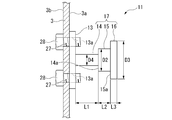
- FIG. 3 is a side view of the lock convex portion 11.
- FIG. 4 is a front view of the lock convex portion 11. As shown in FIGS. 3 and 4, the lock convex portion 11 has a base portion 13 fixed to the back surface 3a of the door 3 and a stepped shaft portion 17 protruding from the base portion 13.
- the base portion 13 is a rectangular plate-shaped member that is long in the horizontal direction when the back surface 3a of the door 3 is viewed.
- Female screw portions 13a are formed at the four corners of the base portion 13.
- a through hole 27 is formed at a portion of the door 3 corresponding to the female screw portion 13a.
- the stepped shaft portion 17 projects along the normal direction (horizontal direction) of the base portion 13. That is, the stepped shaft portion 17 projects along the opening / closing direction of the door 3.
- the stepped shaft portion 17 is integrally formed with the first shaft portion 14 protruding from the base portion 13 and the end portion of the first shaft portion 14 on the opposite side of the base portion 13 (protruding direction of the stepped shaft portion 17).
- the second shaft portion 15 whose diameter is expanded from the first shaft portion 14 via the first step portion 14a and the end portion of the second shaft portion 15 on the opposite side of the base portion 13 are integrally molded and formed into a second. It has a third shaft portion 16 whose diameter is expanded through the second step portion 15a rather than the shaft portion 15.
- the axial length L2 of the second shaft portion 15 is shorter than the axial length L1 of the first shaft portion 14.
- the axial length L3 of the third shaft portion 16 is shorter than the axial length L2 of the second shaft portion 15.
- the first shaft portion 14 and the second shaft portion 15 are formed in a columnar shape, and the third shaft portion 16 is formed in a substantially disk shape.
- FIG. 5 is a side view of the hook 12.
- FIG. 6 is a view taken along the arrow A of FIG.
- the hook 12 includes a rotation shaft (an example of a rotation axis in the claims) 18 rotatably provided on the peripheral edge of the opening 2b in the housing 2, and a rotation shaft 18. It has an engaging portion (an example of a hook-side engaging portion in the claim) 19 and a pressing portion (an example of a hook-side pressing portion in the claim) 20 provided on both sides thereof.
- the rotation shaft 18 is arranged along the front surface 2a of the housing 2 and along the horizontal direction, and is rotatably supported by the housing 2.
- the engaging portion 19 is formed by bending a rectangular plate-shaped member. Specifically, the engaging portion 19 is a support plate 21 extending from the rotating shaft 18 in one direction, and an engaging piece 22 bent and extended from an end portion of the support plate 21 opposite to the rotating shaft 18. And have. The angle between the support plate 21 and the engaging piece 22 is approximately 90 °.
- the engagement piece 22 is formed with an opening (an example of the second opening in the claim) 23 at most of the center in the plane direction.
- the opening 23 is formed in a circular shape when viewed from the normal direction of the engaging piece 22.
- a receiving opening (an example of the first opening in the claims) 24 is formed at the tip of the engaging piece 22 on the opposite side of the support plate 21.
- the width W1 of the engaging piece 22 in the receiving opening 24 as seen from the normal direction is smaller than the diameter D1 of the opening 23. More specifically, the diameter D1 of the opening 23 is larger than the shaft diameter D2 of the second shaft portion 15 and smaller than the shaft diameter D3 of the third shaft portion 16. The width W1 of the receiving opening 24 is larger than the shaft diameter D4 of the first shaft portion 14 and smaller than the shaft diameter D2 of the second shaft portion 15.
- the pressing portion 20 provided on the side opposite to the engaging portion 19 with the rotating shaft 18 interposed therebetween is formed by bending a rectangular plate-shaped member.
- the pressing portion 20 is an extension piece 25 extending from the rotation shaft 18 on the same plane as the support plate 21 of the engagement portion 19 and extending in the other direction opposite to the support plate 21. It has a pressed plate 26 bent and extended from an end portion of the piece 25 opposite to the rotation shaft 18.
- the bending direction of the pressed plate 26 is opposite to the bending direction of the engaging piece 22 of the engaging portion 19.
- the angle between the extension piece 25 and the pressed plate 26 is larger than the angle between the support plate 21 and the engagement piece 22.
- the hook 12 thus formed is arranged so that the engaging portion 19 faces the back surface 3a side of the door 3.
- the hook 12 swings in the vertical direction about the rotation shaft 18 while facing the back surface 3a side of the door 3.
- the pressing portion 20 swings in the vertical direction about the rotation shaft 18 while facing the inside of the housing 2.
- the hook 12 arranged at the upper end is formed so that the weight of the pressing portion 20 is heavier than the weight of the engaging portion 19.
- the hook 12 arranged at the lower end portion is formed so that the weight of the engaging portion 19 is heavier than the weight of the pressing portion 20. Therefore, in the hook 12 arranged at the upper end portion, normally, the pressing portion 20 rises downward and the engaging portion 19 rises upward due to the weight of the hook 12 without external force.
- the hook 12 arranged at the lower end portion normally raises the engaging portion 19 downward and the pressing portion 20 upward due to the weight of the hook 12 without external force.
- the handle lock state is released.
- the tip end (the other end) of the lock rod 9 is positioned directly below the pressed plate 26 in the engaging portion 19.
- the tip end (the other end) of the lock rod 9 is positioned directly above the pressed plate 26 in the engaging portion 19.
- the peripheral edge of the opening 2b in the housing 2 may be cut out so as to avoid interference with the engaging portion 19.
- FIG. 1 the peripheral edge of the opening 2b is cut out and shown.
- the engaging portion 19 is located in front of the opening 2b (on the door 3 side).
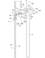
- 7 to 10 are operation explanatory views of the lock mechanism 5.
- the operations of the two lock mechanisms 5 provided at the upper and lower ends of the housing 2 and the door 3 are the same. Therefore, in the following description, of the two lock mechanisms 5, the lock mechanism 5 provided at the upper end portion of the housing 2 and the door 3 will be described, and if necessary, the lower end portion of the housing 2 and the door 3 will be described.
- the provided lock mechanism 5 will be described.
- the hook 12 arranged at the upper end of the housing 2 is normally engaged with the pressing portion 20 downward due to the weight of the hook 12 without external force. Part 19 gets up upward.
- the lock rod 9 slides in the vertical direction as shown in FIG. 8 (see arrow Y3 in FIG. 8). Then, the tip of the lock rod 9 pushes up the pressed plate 26 of the hook 12. As a result, the hook 12 is rotated around the rotation shaft 18 (see arrow Y4 in FIG. 8).
- the engaging portion 19 of the hook 12 is lowered, and the hook 12 is engaged with the lock convex portion 11 provided on the door 3.
- the first shaft portion 14 of the lock convex portion 11 is positioned at the position of the engaging piece 22 of the hook 12.
- the width W1 of the receiving opening 24 in the engaging piece 22 is larger than the shaft diameter D4 of the first shaft portion 14. Therefore, when the engaging portion 19 of the hook 12 is lowered, the first shaft portion 14 of the lock convex portion 11 passes through the receiving opening 24 of the engaging piece 22, and is further inserted into the opening 23 of the engaging piece 22.
- the shaft portion 14 is positioned.
- such a state is referred to as an engagement preliminary state of the hook 12. In the pre-engagement state of the hook 12, the handle is locked.
- the diameter D1 of the opening 23 in the engaging piece 22 of the hook 12 is larger than the shaft diameter D2 of the second shaft portion 15 and smaller than the shaft diameter D3 of the third shaft portion 16. Therefore, when the lock convex portion 11 is moved outward together with the door 3, the second shaft portion 15 fits into the opening 23 of the engaging piece 22, and the third shaft portion 16 is fitted to the engaging piece 22. bump into. In this state, the hook 12 is completely engaged with the lock protrusion 11. Hereinafter, such a state is referred to as an engaged state of the hook 12. This restricts the outward movement of the lock protrusion 11. By restricting the movement of the lock protrusion 11 to the outside, the movement of the door 3 in the opening direction is also restricted.
- the width W1 of the receiving opening 24 in the engaging piece 22 is smaller than the shaft diameter D2 of the second shaft portion 15. Therefore, in a state where the second shaft portion 15 is fitted in the opening 23 of the engaging piece 22, for example, the engaging portion 19 of the hook 12 tries to rise due to an impact when an arc flash or the like occurs in the housing 2. Is blocked. That is, the disengagement of the hook 12 from the engaged state is prevented.
- the circumference of the opening 23 in the engaging piece 22 is the first regulation that regulates the escape from the lock convex portion 11 in the axial direction (the protruding direction of the lock convex portion 11). It functions as a unit 31.
- the periphery of the receiving opening 24 in the engaging piece 22 regulates the engagement release direction from the lock convex portion 11 (the direction intersecting the protruding direction of the lock convex portion 11). It functions as the second regulation unit 32.
- the lock convex portion 11 is fastened and fixed to the door 3 by a bolt 28 inserted from the surface 3b side of the door 3. Therefore, as shown in FIG. 10, the lock convex portion 11 can be removed from the door 3 by loosening and removing the bolt 28 from the surface 3b side of the door 3. As a result, the door 3 can be opened.
- the control panel 1 in the above-mentioned first embodiment includes lock mechanisms 5 provided at both upper and lower ends.
- the lock mechanism 5 includes a lock convex portion 11 provided on the door 3 and a hook 12 provided on the housing 2 and capable of engaging with the lock convex portion 11.
- the hook 12 arranged at the upper end is normally in a disengaged state with respect to the lock convex portion 11 in which the engaging portion 19 is raised upward and no external force is applied.
- the hook 12 arranged at the lower end is normally in a disengaged state with the engaging portion 19 facing downward to the lock convex portion 11 without an external force.
- the hook 12 has a pressed plate 26 pressed by a lock rod 9 different from the hook 12, and an engaging piece 22.
- the engaging piece 22 is engaged with the lock convex portion 11.
- the lock mechanism 5 can be configured with such a simple structure. Further, since the lock mechanism 5 can be operated in conjunction with the handle unit 4, the opening and closing work of the door 3 can be simplified while satisfying the explosion-proof function of the control panel 1.
- the lock convex portion 11 has a stepped shaft portion 17 including a first shaft portion 14, a second shaft portion 15, and a third shaft portion 16.
- the engaging piece 22 forms an opening 23 and a receiving opening 24, and has a first regulating portion 31 and a second regulating portion 32.
- the first regulating portion 31 can regulate the axial disconnection from the lock convex portion 11.
- the second regulating portion 32 can regulate the disconnection from the lock convex portion 11 in the disengagement direction. Therefore, the lock mechanism 5 can surely satisfy the explosion-proof function of the control panel 1.
- the lock convex portion 11 By forming the lock convex portion 11 into a stepped shape having the first shaft portion 14, the second shaft portion 15, and the third shaft portion 16, the state in which the engaging piece 22 is interposed in the first shaft portion 14 and the second Two states can be obtained in which the opening 23 of the engaging piece 22 is fitted in the biaxial portion 15. Therefore, if there is no abnormality in the control panel 1, the lock mechanism 5 can be easily released, so that the lock mechanism 5 can be easily used.
- the hook 12 can be easily arranged by providing the lock convex portion 11 on the door 3 side and the hook 12 on the housing 2 side. If the hook 12 is to be provided on the door 3 side, the door 3 may need to be processed in order to secure an operating space for the hook 12. Therefore, by providing the lock convex portion 11 on the door 3 side and the hook 12 on the housing 2 side, the lock mechanism 5 can be easily provided on the existing control panel 1.
- the lock rod 9 is used as a means for pressing the pressed plate 26 of the hook 12.
- the lock rod 9 is often provided for engaging with the peripheral edge of the opening 2b of the housing 2.
- the lock mechanism 5 can be further simplified. Further, the lock mechanism 5 can be more easily provided on the existing control panel 1.
- the lock convex portion 11 is fastened and fixed to the door 3 by a bolt 28 inserted from the surface 3b side of the door 3. Therefore, the lock convex portion 11 can be easily removed from the surface 3b side of the door 3. Therefore, in a state where the second shaft portion 15 is fitted in the opening 23 of the engaging piece 22, the door 3 is deformed or the lock rod 9 is deformed by an impact when an arc flash or the like occurs in the housing 2, for example. Even if it does, the lock mechanism 5 can be easily disengaged and the door 3 can be opened.
- FIG. 11 is a schematic configuration diagram of the hook 12 showing the first modification.
- the angle between the extending piece 25 and the pressed plate 26 is the same as that of the extending piece 25 and the pressed plate 26 of the first embodiment described above. Less than the angle between. Further, the pressed plate 26 is bent and formed. Therefore, in the pre-engagement state of the hook 12, the pressed plate 26 is engaged with the peripheral edge of the opening 2b of the housing 2.
- the same effect as that of the above-mentioned first embodiment is obtained. Further, when the door 3 is closed, the door 3 is engaged with the housing 2 at three points. That is, the door 3 is engaged with the housing 2 by the handle unit 4 and the two pressed plates 26. Therefore, the closed state of the door 3 can be firmly maintained, and the explosion-proof function of the control panel 1 can be further improved.
- the present invention is not limited to this, and any convex shape that can be engaged with the hook 12 may be used.
- the hook 12 is restricted to a portion corresponding to the first regulating portion 31 that regulates the protrusion in the protruding direction with respect to the convex shape, and the hook 12 is restricted from coming out in the direction intersecting the protruding direction with respect to the convex shape. It is desirable to provide a portion corresponding to the second regulation unit 32.
- FIG. 12 is a schematic configuration diagram showing the details of the lock mechanism 105 among the control panels 101 in the second embodiment.
- FIG. 12 corresponds to FIG. 7 in the above-mentioned first embodiment.
- the same embodiments as those of the above-described first embodiment are designated by the same reference numerals and the description thereof will be omitted.
- the control panel 101 in the second embodiment includes a housing 2, a door 3 for opening and closing the opening 2b of the housing 2, and a handle unit 4 provided in the door 3 (see FIG. 1 and the like). , Not shown in FIG. 12) and a locking mechanism 105 provided on the housing 2 and the door 3.
- the locking mechanism 105 is a corresponding lock at both upper and lower ends of the housing 2 and the door 3.
- the two lock mechanisms 5 provided at the upper and lower ends of the housing 2 and the door 3 are arranged upside down in the vertical direction, and have the same structure.
- the basic configuration is the same as that of the first embodiment described above.
- the difference between the first embodiment and the second embodiment is that the lock mechanism 5 of the first embodiment and the lock mechanism 105 of the second embodiment are different.
- the lock mechanism 105 provided at the upper end portions of the housing 2 and the door 3 will be described, and the lock mechanism 105 provided at the lower end portions of the housing 2 and the door 3 will be described as necessary.
- the lock mechanism 105 will be described.
- the lock mechanism 105 includes a lock convex portion (an example of the convex portion in the claim) 111 provided on the back surface 3a of the door 3 and a hook 112 provided on the peripheral edge of the opening 2b of the housing 2. ..
- the lock convex portion 111 has a base portion 113 fixed to the back surface 3a of the door 3 and a shaft portion 117 protruding from the base portion 113.
- the base portion 113 has a contact portion 113a that comes into contact with the back surface 3a of the door 3 and a pedestal portion 113b that is bent and extended from the upper end of the contact portion 113a toward the housing 2 side and along the horizontal direction. And have.
- the contact portion 113a is fastened and fixed to the door 3 by a bolt 28 inserted from the surface 3b of the door 3.
- a shaft portion 117 is projected along the vertical direction on the upper surface of the pedestal portion 113b.
- the shaft portion 117 is integrally formed with a columnar shaft portion main body (an example of the fourth shaft portion in the claim) 117a and the upper end of the shaft portion main body 117a, and has a larger diameter than the shaft portion main body 117a via a step portion 117c. It has a disk-shaped head formed (an example of the fifth shaft portion in the claim) 117b.
- FIG. 13 is a view taken along the line B of FIG.
- the hook 112 is rotatably provided on the peripheral edge of the opening 2b in the housing 2 and is rotatably provided on the rotation shaft (an example of the rotation axis in the claims) 118 and the rotation shaft 118.
- 119 of the support plate 133 supported by the support plate 133 an engaging portion extending from one side 133a of the support plate 133 toward the door 3 side (an example of the hook side engaging portion in the claims), and the support plate 133.
- It has a pressing portion (an example of the hook-side pressing portion in the claim) 120 extending from one side 133a toward the side opposite to the engaging portion 119.
- the hook 112 is formed so that one side 133a of the support plate 133 is located on the lower side due to its own weight.
- One side 133a of the support plate 133 runs in the horizontal direction without receiving an external force.
- the engaging portion 119 is formed by bending a rectangular plate-shaped member. Specifically, the engaging portion 119 is bent and extended from an extension plate 121 extending along one side 133a of the support plate 133 and an end portion of the extension plate 121 opposite to the support plate 133. It has a piece 122 and. The engaging piece 122 extends diagonally upward with one side 133a of the support plate 133 located on the lower side.
- the engaging piece 122 is formed with an opening (an example of the fourth opening in the claim) 123 in most of the center in the plane direction.
- the opening 123 is formed in a semicircular shape in which the side opposite to the support plate 133 is convex when viewed from the normal direction of the engaging piece 22.
- the size of the opening 123 is such that both the shaft portion main body 117a and the head portion 117b of the shaft portion 117 can pass through.
- a small opening (an example of the third opening in the claim) 124 is formed in the center of the convex side of the opening 123.
- the small opening 124 communicates with the opening 123. Further, the tip of the small opening 124 on the opposite side of the opening 123 does not penetrate the outside of the engaging piece 122 and is closed.
- the size of the small opening 124 is such that the shaft body 117a of the shaft 117 can pass through and the head 117b cannot pass through.
- the pressing portion 120 provided on the side opposite to the engaging portion 119 with the engaging piece 122 of the support plate 133 interposed therebetween is formed by bending a rectangular plate-shaped member.
- the pressing portion 120 includes a pressed plate 126 extending along one side 133a of the support plate 133 and a return plate bent and extended from an end portion of the pressed plate 126 opposite to the support plate 133. It has 134 and. The angle between the pressed plate 126 and the return plate 134 is approximately 90 °.
- the hook 12 thus formed has a shape in which the engaging portion 119 swings in the vertical direction around the rotation shaft 18. Then, in the state where the handle lock state is released, the tip end (the other end) of the lock rod 9 is positioned directly under the pressed plate 126. In the hook 112 arranged at the lower end portion, the tip end (the other end) of the lock rod 9 is positioned directly above the pressed plate 126.
- FIGS. 12, 14, and 15. 14 and 15 are operation explanatory views of the lock mechanism 105.
- FIG. 15 corresponds to FIG.
- the operations of the two lock mechanisms 105 provided at the upper and lower ends of the housing 2 and the door 3 are the same. Therefore, in the following description, of the two lock mechanisms 105, the lock mechanism 105 provided at the upper end portion of the housing 2 and the door 3 will be described, and if necessary, the lower end portion of the housing 2 and the door 3 will be described.
- the provided lock mechanism 105 will be described.
- the hook 112 arranged at the upper end of the housing 2 is normally not subject to external force, and normally, one side 133a of the support plate 133 is on the lower side due to the weight of the hook 112.
- the engaging piece 122 rises diagonally upward.
- the lock rod 9 slides in the vertical direction as shown in FIG. 14 (see arrow Y6 in FIG. 14). Then, the tip of the lock rod 9 pushes up the pressed plate 126 of the hook 112. As a result, the hook 112 is rotated around the rotation shaft 118 (see arrow Y7 in FIG. 14).
- the engaging portion 119 of the hook 112 is lowered, and the hook 112 is engaged with the lock convex portion 111 provided on the door 3.
- the shaft portion of the lock convex portion 111 is located at the position of the opening 123 formed in the engaging piece 122 of the hook 112. 117 is located.
- the size of the opening 123 is such that both the shaft portion main body 117a and the head portion 117b of the shaft portion 117 can pass through.
- the size of the small opening 124 in the engaging piece 122 of the hook 112 is a size that allows the shaft portion main body 117a of the shaft portion 117 to pass through. Therefore, when the lock convex portion 111 is moved outward together with the door 3, the shaft portion main body 117a of the shaft portion 117 is fitted into the small opening portion 124 of the engaging piece 122, and the tip portion of the small opening portion 124 is fitted. The shaft body 117a abuts against. In this state, the hook 112 is completely engaged with the lock protrusion 111. Hereinafter, such a state is referred to as an engaged state of the hook 112. This restricts the outward movement of the lock protrusion 111. By restricting the movement of the lock protrusion 111 to the outside, the movement of the door 3 in the opening direction is also restricted.
- the size of the small opening 124 is such that the head 117b of the shaft portion 117 cannot pass through. Therefore, in a state where the shaft portion main body 117a is fitted in the small opening 124 of the engaging piece 122, the engaging portion 119 of the hook 112 tries to rise due to an impact when an arc flash or the like occurs in the housing 2, for example. Is blocked. That is, the disengagement of the hook 112 from the engaged state is prevented.
- the periphery of the small opening 124 in the engaging piece 122 restricts the lock convex portion 111 from coming off from the shaft portion 117 in the axial direction (protruding direction of the shaft portion 117). It functions as the first regulation unit 131. Further, the periphery of the small opening 124 functions as a second regulating portion 132 that regulates the escape of the shaft portion 117 in the direction intersecting the protruding direction (see FIG. 13). Therefore, the above-mentioned second embodiment has the same effect as the above-mentioned first embodiment.
- the present invention is not limited to this, and any convex shape that can be engaged with the hook 112 may be used.
- the hook 112 is restricted from the portion corresponding to the first restricting portion 131 that regulates the protrusion in the protruding direction with respect to the convex shape and the portion corresponding to the first restricting portion 131 that regulates the withdrawal in the direction intersecting the protruding direction with respect to the convex shape. It is desirable to provide a portion corresponding to the second regulation unit 132.
- the configuration of the above-mentioned first modification may be adopted as the configuration of the pressed plate 126. That is, in the handle locked state (engaged state of the hook 12), the pressed plate 126 may be configured to be engaged with the peripheral edge of the opening 2b of the housing 2.
- FIG. 16 is a schematic configuration diagram of the engaging pieces 22, 122 and the lock rod 9 of the hooks 12, 112 in the second modification.
- the lock rod 9 has a first rod portion 9a and a second rod formed on the tip end side of the first rod portion 9a via a stepped portion 9c rather than the first rod portion 9a. It may have a part 9b and.
- through holes 26a and 126a that cannot pass through the first rod portion 9a and can pass through the second rod portion 9b are formed in the pressed plates 26 and 126 of the first embodiment and the second embodiment. With this configuration, the pressed plates 26 and 126 are pushed up (pushed down) by the stepped portion 9c of the lock rod 9 when the handle is locked.
- the length of the second rod portion 9b is a length that can be engaged with the peripheral edge of the opening 2b of the housing 2 in the handle locked state. Therefore, according to the second modification, the same effect as that of the first modification described above is obtained.
- FIG. 17 is a schematic configuration diagram of the lock rod 9 in the third modification.
- the lock rod 9 may have a sublock rod 109 formed so as to project from the outer peripheral surface near the tip (the other end).
- the sublock rod 109 is formed so as to protrude from the lock rod 9 so as to avoid interference with the pressed plates 26 and 126 of the first embodiment and the second embodiment.
- the lock rod 9 is operated in conjunction with the operation of the handle unit 4 .
- the present invention is not limited to this, and the lock rod 9 may be operated independently.
- a pressing portion capable of pressing the pressed plates 26 and 126 may be provided instead of the lock rod 9, a pressing portion capable of pressing the pressed plates 26 and 126 may be provided. In these cases, the lock rod 9 and the pressing portion are configured to be able to operate from the outside of the door 3 with the door 3 closed.
- hooks 12 and 112 are provided on the housing 2 and the lock protrusions 11 and 111 are provided on the door 3 .
- the present invention is not limited to this, and hooks 12 and 112 may be provided on the door 3 and lock protrusions 11 and 111 may be provided on the housing 2.
- the control panels 1, 101 include lock mechanisms 5, 105.
- the hooks 12, 112 of the locking mechanisms 5, 105 the hooks 12, 112 arranged at the upper ends are normally not subject to external force, and the engaging portions 19, 119 are normally raised upward to lock the convex portion 11. , 111 is disengaged.
- the hooks 12, 112 arranged at the lower end are normally in a state in which the engaging portions 19, 119 are disengaged from the downward lock convex portions 11, 111, to which an external force is not applied.
- the hooks 12 and 112 have a pressed plate 26 and 126 pressed by a lock rod 9 different from the hooks 12 and 112, and engaging pieces 22 and 122.
- the lock mechanisms 5, 105 can be configured with such a simple structure. Further, while satisfying the explosion-proof function of the control panels 1, 101, the opening / closing work of the door 3 can be simplified.
Landscapes
- Engineering & Computer Science (AREA)
- Mechanical Engineering (AREA)
- Structural Engineering (AREA)
- Physics & Mathematics (AREA)
- Electromagnetism (AREA)
- Civil Engineering (AREA)
- Casings For Electric Apparatus (AREA)
Priority Applications (4)
| Application Number | Priority Date | Filing Date | Title |
|---|---|---|---|
| US17/995,964 US12180760B2 (en) | 2020-05-29 | 2020-05-29 | Lock mechanism |
| JP2021500761A JP7038890B1 (ja) | 2020-05-29 | 2020-05-29 | ロック機構 |
| PCT/JP2020/021371 WO2021240794A1 (ja) | 2020-05-29 | 2020-05-29 | ロック機構 |
| CN202080045676.6A CN114072565B (zh) | 2020-05-29 | 2020-05-29 | 锁定机构 |
Applications Claiming Priority (1)
| Application Number | Priority Date | Filing Date | Title |
|---|---|---|---|
| PCT/JP2020/021371 WO2021240794A1 (ja) | 2020-05-29 | 2020-05-29 | ロック機構 |
Publications (1)
| Publication Number | Publication Date |
|---|---|
| WO2021240794A1 true WO2021240794A1 (ja) | 2021-12-02 |
Family
ID=78723229
Family Applications (1)
| Application Number | Title | Priority Date | Filing Date |
|---|---|---|---|
| PCT/JP2020/021371 Ceased WO2021240794A1 (ja) | 2020-05-29 | 2020-05-29 | ロック機構 |
Country Status (4)
| Country | Link |
|---|---|
| US (1) | US12180760B2 (https=) |
| JP (1) | JP7038890B1 (https=) |
| CN (1) | CN114072565B (https=) |
| WO (1) | WO2021240794A1 (https=) |
Families Citing this family (1)
| Publication number | Priority date | Publication date | Assignee | Title |
|---|---|---|---|---|
| CN117136491A (zh) * | 2021-04-01 | 2023-11-28 | 三菱电机株式会社 | 功率转换装置 |
Citations (3)
| Publication number | Priority date | Publication date | Assignee | Title |
|---|---|---|---|---|
| DE29607611U1 (de) * | 1996-04-26 | 1996-07-18 | Oskar D. Biffar GmbH & Co KG, 67480 Edenkoben | Verriegelungsvorrichtung zum Einbau in Fenstern |
| JP2007278004A (ja) * | 2006-04-11 | 2007-10-25 | Suehiro Kanagu Kk | スチール扉の施錠装置 |
| JP2015074946A (ja) * | 2013-10-10 | 2015-04-20 | 株式会社栃木屋 | 施錠装置 |
Family Cites Families (16)
| Publication number | Priority date | Publication date | Assignee | Title |
|---|---|---|---|---|
| US2202534A (en) * | 1939-07-28 | 1940-05-28 | John V Mcgunn | Electric time lock for safes |
| FR2681632B1 (fr) * | 1991-09-20 | 1993-11-19 | Cga Hbs Cie Gle Automatisme | Systeme de fermeture anti-effraction d'une porte d'armoire metallique. |
| SE502225C2 (sv) * | 1994-01-12 | 1995-09-18 | Whirlpool Europ | Mikrovågsugn |
| US6425612B1 (en) * | 1999-12-22 | 2002-07-30 | Tom Stephens Schaeffer | Gravity operated gate latch |
| TWM278795U (en) * | 2005-06-08 | 2005-10-21 | Inventec Corp | Push-type buckle device |
| US20080148642A1 (en) * | 2006-09-29 | 2008-06-26 | Alain Herve Mathieu | Arc resistant switchgear door and frame assembly, through the door racking system, and air cooling and ventilation system |
| JP2012046912A (ja) * | 2010-08-25 | 2012-03-08 | Ykk Ap株式会社 | 建具 |
| US8419141B2 (en) * | 2011-01-27 | 2013-04-16 | Eaton Corporation | Switchgear door latching system |
| US8720117B2 (en) * | 2011-03-15 | 2014-05-13 | Darron Phillips | Explosive breach training system |
| EP2898164B1 (en) * | 2012-09-12 | 2019-04-10 | Patrick John Doherty | A door guard assembly |
| DE202012103608U1 (de) * | 2012-09-20 | 2012-10-24 | Kiekert Aktiengesellschaft | Kraftfahrzeugtürschloss |
| JP2014114614A (ja) | 2012-12-11 | 2014-06-26 | Daiken Co Ltd | 収納ボックスの施錠装置 |
| US20160040458A1 (en) * | 2014-08-06 | 2016-02-11 | Camfil Usa, Inc | Dust collector with explosion resistant door |
| US10100554B2 (en) * | 2014-08-26 | 2018-10-16 | Northland Products, Inc. | Gravity-actuated latch mechanism |
| JP6587835B2 (ja) * | 2015-06-08 | 2019-10-09 | タキゲン製造株式会社 | 多点締め込み式ロックシステム及びこれを用いた防爆扉 |
| JP7023734B2 (ja) | 2018-02-13 | 2022-02-22 | ホーチキ株式会社 | ラッチ式解錠装置 |
-
2020
- 2020-05-29 WO PCT/JP2020/021371 patent/WO2021240794A1/ja not_active Ceased
- 2020-05-29 CN CN202080045676.6A patent/CN114072565B/zh active Active
- 2020-05-29 JP JP2021500761A patent/JP7038890B1/ja active Active
- 2020-05-29 US US17/995,964 patent/US12180760B2/en active Active
Patent Citations (3)
| Publication number | Priority date | Publication date | Assignee | Title |
|---|---|---|---|---|
| DE29607611U1 (de) * | 1996-04-26 | 1996-07-18 | Oskar D. Biffar GmbH & Co KG, 67480 Edenkoben | Verriegelungsvorrichtung zum Einbau in Fenstern |
| JP2007278004A (ja) * | 2006-04-11 | 2007-10-25 | Suehiro Kanagu Kk | スチール扉の施錠装置 |
| JP2015074946A (ja) * | 2013-10-10 | 2015-04-20 | 株式会社栃木屋 | 施錠装置 |
Also Published As
| Publication number | Publication date |
|---|---|
| US20230184011A1 (en) | 2023-06-15 |
| JPWO2021240794A1 (https=) | 2021-12-02 |
| US12180760B2 (en) | 2024-12-31 |
| JP7038890B1 (ja) | 2022-03-18 |
| CN114072565A (zh) | 2022-02-18 |
| CN114072565B (zh) | 2023-02-28 |
Similar Documents
| Publication | Publication Date | Title |
|---|---|---|
| TWI574598B (zh) | 具有快拆功能的固定機構及其相關電子裝置 | |
| JP4625889B2 (ja) | 車両用ラッチ装置 | |
| US8807900B2 (en) | Snap faster | |
| EP3396090B1 (en) | Vehicle door handle device | |
| JP7038890B1 (ja) | ロック機構 | |
| JP5919119B2 (ja) | ドア装置 | |
| TWI508641B (zh) | 電子裝置及其底座結構 | |
| JPH0557448B2 (https=) | ||
| CN113741627A (zh) | 卡扣结构 | |
| HK1255950A1 (zh) | 相互固定特别是用於门/窗的关闭系统组成部件的方案 | |
| US20090025434A1 (en) | Buckling assembly and casing structure using the same | |
| JP2011106180A (ja) | 屋外盤の筐体構造 | |
| JP2014057453A (ja) | スイッチギヤの扉ロック装置 | |
| JP4678346B2 (ja) | 開閉器の外部操作ハンドル | |
| US3086092A (en) | Variable depth operating mechanism sub-assemblies | |
| JP4434877B2 (ja) | 押ボタンスイッチ | |
| JP5124841B2 (ja) | シリンダ錠の固定機構 | |
| CN100408798C (zh) | 门开关用把手装置 | |
| CN117119728B (zh) | Led箱体及具有其的led显示装置 | |
| CN108063066B (zh) | 开关装置的扳动组合改良结构 | |
| JP4629647B2 (ja) | 制御ハンドル装置 | |
| JP4354335B2 (ja) | 自動車のフードロック装置 | |
| TWI736977B (zh) | 固定架 | |
| JP2003014191A (ja) | 昇降脚具 | |
| JP5836356B2 (ja) | 遊技機 |
Legal Events
| Date | Code | Title | Description |
|---|---|---|---|
| ENP | Entry into the national phase |
Ref document number: 2021500761 Country of ref document: JP Kind code of ref document: A |
|
| 121 | Ep: the epo has been informed by wipo that ep was designated in this application |
Ref document number: 20938288 Country of ref document: EP Kind code of ref document: A1 |
|
| WWE | Wipo information: entry into national phase |
Ref document number: 202217058177 Country of ref document: IN |
|
| NENP | Non-entry into the national phase |
Ref country code: DE |
|
| 122 | Ep: pct application non-entry in european phase |
Ref document number: 20938288 Country of ref document: EP Kind code of ref document: A1 |