WO2021240794A1 - Lock mechanism - Google Patents
Lock mechanism Download PDFInfo
- Publication number
- WO2021240794A1 WO2021240794A1 PCT/JP2020/021371 JP2020021371W WO2021240794A1 WO 2021240794 A1 WO2021240794 A1 WO 2021240794A1 JP 2020021371 W JP2020021371 W JP 2020021371W WO 2021240794 A1 WO2021240794 A1 WO 2021240794A1
- Authority
- WO
- WIPO (PCT)
- Prior art keywords
- hook
- door
- opening
- housing
- shaft
- Prior art date
Links
- 230000007246 mechanism Effects 0.000 title claims abstract description 75
- 230000002093 peripheral effect Effects 0.000 claims description 19
- 230000001105 regulatory effect Effects 0.000 claims description 9
- 230000004048 modification Effects 0.000 description 19
- 238000012986 modification Methods 0.000 description 19
- 238000010586 diagram Methods 0.000 description 8
- 238000005452 bending Methods 0.000 description 6
- 230000004323 axial length Effects 0.000 description 4
- 230000000694 effects Effects 0.000 description 4
- 238000006243 chemical reaction Methods 0.000 description 3
- NJPPVKZQTLUDBO-UHFFFAOYSA-N novaluron Chemical compound C1=C(Cl)C(OC(F)(F)C(OC(F)(F)F)F)=CC=C1NC(=O)NC(=O)C1=C(F)C=CC=C1F NJPPVKZQTLUDBO-UHFFFAOYSA-N 0.000 description 3
- 230000005856 abnormality Effects 0.000 description 1
- 238000004880 explosion Methods 0.000 description 1
Images


Classifications
-
- E—FIXED CONSTRUCTIONS
- E05—LOCKS; KEYS; WINDOW OR DOOR FITTINGS; SAFES
- E05C—BOLTS OR FASTENING DEVICES FOR WINGS, SPECIALLY FOR DOORS OR WINDOWS
- E05C9/00—Arrangements of simultaneously actuated bolts or other securing devices at well-separated positions on the same wing
- E05C9/04—Arrangements of simultaneously actuated bolts or other securing devices at well-separated positions on the same wing with two sliding bars moved in opposite directions when fastening or unfastening
-
- E—FIXED CONSTRUCTIONS
- E05—LOCKS; KEYS; WINDOW OR DOOR FITTINGS; SAFES
- E05C—BOLTS OR FASTENING DEVICES FOR WINGS, SPECIALLY FOR DOORS OR WINDOWS
- E05C3/00—Fastening devices with bolts moving pivotally or rotatively
- E05C3/02—Fastening devices with bolts moving pivotally or rotatively without latching action
- E05C3/06—Fastening devices with bolts moving pivotally or rotatively without latching action with operating handle or equivalent member moving otherwise than rigidly with the bolt
-
- E—FIXED CONSTRUCTIONS
- E05—LOCKS; KEYS; WINDOW OR DOOR FITTINGS; SAFES
- E05B—LOCKS; ACCESSORIES THEREFOR; HANDCUFFS
- E05B17/00—Accessories in connection with locks
- E05B17/20—Means independent of the locking mechanism for preventing unauthorised opening, e.g. for securing the bolt in the fastening position
- E05B17/2084—Means to prevent forced opening by attack, tampering or jimmying
- E05B17/2088—Means to prevent disengagement of lock and keeper
-
- E—FIXED CONSTRUCTIONS
- E05—LOCKS; KEYS; WINDOW OR DOOR FITTINGS; SAFES
- E05B—LOCKS; ACCESSORIES THEREFOR; HANDCUFFS
- E05B63/00—Locks or fastenings with special structural characteristics
- E05B63/24—Arrangements in which the fastening members which engage one another are mounted respectively on the wing and the frame and are both movable, e.g. for release by moving either of them
- E05B63/242—Auxiliary bolts on the frame, actuated by bolts on the wing, or vice versa
-
- E—FIXED CONSTRUCTIONS
- E05—LOCKS; KEYS; WINDOW OR DOOR FITTINGS; SAFES
- E05C—BOLTS OR FASTENING DEVICES FOR WINGS, SPECIALLY FOR DOORS OR WINDOWS
- E05C3/00—Fastening devices with bolts moving pivotally or rotatively
- E05C3/006—Fastening devices with bolts moving pivotally or rotatively about an axis parallel to the surface on which the fastener is mounted
- E05C3/008—Fastening devices with bolts moving pivotally or rotatively about an axis parallel to the surface on which the fastener is mounted parallel to the wing edge
-
- E—FIXED CONSTRUCTIONS
- E05—LOCKS; KEYS; WINDOW OR DOOR FITTINGS; SAFES
- E05C—BOLTS OR FASTENING DEVICES FOR WINGS, SPECIALLY FOR DOORS OR WINDOWS
- E05C3/00—Fastening devices with bolts moving pivotally or rotatively
- E05C3/02—Fastening devices with bolts moving pivotally or rotatively without latching action
- E05C3/04—Fastening devices with bolts moving pivotally or rotatively without latching action with operating handle or equivalent member rigid with the bolt
- E05C3/041—Fastening devices with bolts moving pivotally or rotatively without latching action with operating handle or equivalent member rigid with the bolt rotating about an axis perpendicular to the surface on which the fastener is mounted
- E05C3/042—Fastening devices with bolts moving pivotally or rotatively without latching action with operating handle or equivalent member rigid with the bolt rotating about an axis perpendicular to the surface on which the fastener is mounted the handle being at one side, the bolt at the other side or inside the wing
-
- E—FIXED CONSTRUCTIONS
- E06—DOORS, WINDOWS, SHUTTERS, OR ROLLER BLINDS IN GENERAL; LADDERS
- E06B—FIXED OR MOVABLE CLOSURES FOR OPENINGS IN BUILDINGS, VEHICLES, FENCES OR LIKE ENCLOSURES IN GENERAL, e.g. DOORS, WINDOWS, BLINDS, GATES
- E06B5/00—Doors, windows, or like closures for special purposes; Border constructions therefor
- E06B5/10—Doors, windows, or like closures for special purposes; Border constructions therefor for protection against air-raid or other war-like action; for other protective purposes
- E06B5/12—Doors, windows, or like closures for special purposes; Border constructions therefor for protection against air-raid or other war-like action; for other protective purposes against air pressure, explosion, or gas
-
- E—FIXED CONSTRUCTIONS
- E05—LOCKS; KEYS; WINDOW OR DOOR FITTINGS; SAFES
- E05B—LOCKS; ACCESSORIES THEREFOR; HANDCUFFS
- E05B15/00—Other details of locks; Parts for engagement by bolts of fastening devices
- E05B15/02—Striking-plates; Keepers; Bolt staples; Escutcheons
- E05B15/0205—Striking-plates, keepers, staples
- E05B2015/023—Keeper shape
- E05B2015/0235—Stud-like
-
- E—FIXED CONSTRUCTIONS
- E05—LOCKS; KEYS; WINDOW OR DOOR FITTINGS; SAFES
- E05C—BOLTS OR FASTENING DEVICES FOR WINGS, SPECIALLY FOR DOORS OR WINDOWS
- E05C9/00—Arrangements of simultaneously actuated bolts or other securing devices at well-separated positions on the same wing
- E05C9/18—Details of fastening means or of fixed retaining means for the ends of bars
- E05C9/1825—Fastening means
- E05C9/1833—Fastening means performing sliding movements
- E05C9/185—Fastening means performing sliding movements parallel with actuating bar
- E05C2009/1866—Fastening means performing sliding movements parallel with actuating bar of the keyhole slot type
-
- E—FIXED CONSTRUCTIONS
- E05—LOCKS; KEYS; WINDOW OR DOOR FITTINGS; SAFES
- E05C—BOLTS OR FASTENING DEVICES FOR WINGS, SPECIALLY FOR DOORS OR WINDOWS
- E05C9/00—Arrangements of simultaneously actuated bolts or other securing devices at well-separated positions on the same wing
- E05C9/04—Arrangements of simultaneously actuated bolts or other securing devices at well-separated positions on the same wing with two sliding bars moved in opposite directions when fastening or unfastening
- E05C9/048—Arrangements of simultaneously actuated bolts or other securing devices at well-separated positions on the same wing with two sliding bars moved in opposite directions when fastening or unfastening externally mounted on the wing, i.e. surface mounted
Definitions
- An embodiment of the present invention relates to a locking mechanism.
- a control panel in which a circuit such as a power conversion system is housed has a box-shaped housing having an opening and a door that closes the opening of the housing.
- a circuit such as a power conversion system
- the door and the housing are engaged and the closed state of the door is maintained.
- the locking mechanism includes, for example, a hook that rotates around the axis of rotation, an engaging portion that engages with the hook, and a spring that maintains the engaged or disengaged state of the hook with the engaged portion.
- the lock mechanism as described above has a complicated structure and may be costly. If a lock mechanism is provided separately from the handle, the lock mechanism is engaged and disengaged in addition to the opening and closing work of the handle. For this reason, the opening and closing work of the door may become troublesome in the end.
- the problem to be solved by the present invention is to provide a lock mechanism capable of simplifying the structure while satisfying the explosion-proof function and also simplifying the opening and closing work of the door.
- the locking mechanism of the embodiment includes an engaging portion, a hook, and a pressing portion.
- the engaging portion is provided on either the housing or the door that opens and closes the housing opening of the housing.
- the hook is rotatably provided on either the housing or the door around the rotation axis, is engageable with the engaging portion, and is always disengaged from the engaging portion by its own weight.
- the pressing portion is provided separately from the hook and presses the hook.
- the hook has a hook side engaging portion that is engaged with the engaging portion across the rotation axis, and a hook side that engages the engaging portion and the hook side engaging portion by being pressed by the pressing portion. It has a pressing portion and.
- a view of arrow 5 in FIG. The operation explanatory drawing which shows the lock mechanism of 1st Embodiment.
- the operation explanatory drawing which shows the lock mechanism of 1st Embodiment. which shows the lock mechanism of 1st Embodiment.
- the schematic block diagram which shows the hook of the 1st modification in embodiment The schematic block diagram which shows the control panel of 2nd Embodiment. B arrow view of FIG.
- the operation explanatory drawing which shows the lock mechanism of 2nd Embodiment The operation explanatory drawing which shows the lock mechanism of 2nd Embodiment.
- the schematic block diagram which shows the hook and the lock bar of the 2nd modification in embodiment The schematic block diagram which shows the lock bar of the 3rd modification in embodiment.
- FIG. 1 is a perspective view of a control panel 1 in which a circuit such as a power conversion system is housed.
- the control panel 1 is provided in a box-shaped housing 2 having an opening (an example of a housing opening in the claim) 2b on the front surface 2a, a door 3 for opening and closing the opening 2b of the housing 2, and a door 3.
- the handle unit 4 is provided, and the lock mechanism 5 provided on the housing 2 and the door 3 is provided.
- the vertical direction with the control panel 1 installed is simply referred to as a vertical direction
- the horizontal direction with the control panel 1 installed is simply referred to as a horizontal direction.
- the housing 2 is formed long in the vertical direction.
- the door 3 is rotatably supported via a rotation support member (not shown) provided on one side in the horizontal direction of the opening 2b of the housing 2.
- a handle unit 4 and a lock mechanism 5 are provided on one side of the door 3 opposite to the rotation support member.
- FIG. 2 is a perspective view of the handle unit 4 as viewed from the back surface 3a side of the door 3.
- the handle unit 4 is provided at the center of the door 3 in the vertical direction.
- the handle unit 4 includes a handle (not shown) provided on the front surface 3b side of the door 3, a support 6 provided on the back surface 3a side of the door 3, and an engaging piece 8 rotatably supported by the support 6.
- a handle rotating shaft 7 that penetrates the door 3 and is rotatably supported by the door 3 and the support 6 and connects the handle and the engaging piece 8 (not shown) is provided.
- the support 6 is formed in the shape of a plate long in the vertical direction.
- a handle rotation shaft 7 is connected to the center of the support 6 in the longitudinal direction.
- the engaging piece 8 rotates integrally with a handle (not shown) via the handle rotation shaft 7.
- the engaging piece 8 is in a state where the door 3 is closed and a handle (not shown) is locked (hereinafter referred to as a handle locked state), from the end surface of the support 6 in the lateral direction toward the peripheral edge of the opening 2b in the housing 2. Protrude. As a result, the engaging piece 8 is engaged with the peripheral edge of the opening 2b of the housing 2 in the handle locked state (hereinafter, referred to as the engaged state of the engaging piece 8). Further, the engaging piece 8 is housed in the support 6 when a handle (not shown) is rotated so as to release the handle locked state when the door 3 is opened. As a result, the engaging piece 8 is disengaged from the peripheral edge of the opening 2b in the housing 2 (hereinafter, referred to as the disengaging state of the engaging piece 8).
- a lock rod 9 (an example of a pressing portion in the claim) 9 is supported so as to be slidable and slidable along the vertical direction.
- one lock rod 9 extends in the vertical direction from the support 6 to the upper part of the door 3.
- the other lock bar 9 extends in the vertical direction from the support 6 to the lower part of the door 3.
- the other end of each lock rod 9 is slidably supported by guide portions 10 provided at the upper and lower portions of the back surface 3a of the door 3.
- Each lock rod 9 is slid up and down as the engaging piece 8 (handle not shown) rotates. More specifically, in the disengaged state of the engaging piece 8, the two lock rods 9 are retracted toward the center in the vertical direction of the door 3 (see arrow Y1 in FIG. 2). On the other hand, in the engaged state of the engaging piece 8, the two lock rods 9 are projected in the vertical direction of the door 3 (see arrow Y2 in FIG. 2). Each of these two lock rods 9 operates the lock mechanism 5.
- the lock mechanism 5 is arranged at both upper and lower ends of the housing 2 and the door 3 and close to the other ends of the corresponding lock rods 9.
- the two lock mechanisms 5 provided at the upper and lower ends of the housing 2 and the door 3 are arranged upside down in the vertical direction, and have the same structure. Therefore, in the following description, of the two lock mechanisms 5, the lock mechanism 5 provided at the upper end portion of the housing 2 and the door 3 will be described, and if necessary, the lower end portion of the housing 2 and the door 3 will be described.
- the provided lock mechanism 5 will be described.
- the lock mechanism 5 includes a lock convex portion (an example of the convex portion in the claim) 11 provided on the back surface 3a of the door 3 and a hook 12 provided on the peripheral edge of the opening 2b of the housing 2. ..
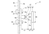
- FIG. 3 is a side view of the lock convex portion 11.
- FIG. 4 is a front view of the lock convex portion 11. As shown in FIGS. 3 and 4, the lock convex portion 11 has a base portion 13 fixed to the back surface 3a of the door 3 and a stepped shaft portion 17 protruding from the base portion 13.
- the base portion 13 is a rectangular plate-shaped member that is long in the horizontal direction when the back surface 3a of the door 3 is viewed.
- Female screw portions 13a are formed at the four corners of the base portion 13.
- a through hole 27 is formed at a portion of the door 3 corresponding to the female screw portion 13a.
- the stepped shaft portion 17 projects along the normal direction (horizontal direction) of the base portion 13. That is, the stepped shaft portion 17 projects along the opening / closing direction of the door 3.
- the stepped shaft portion 17 is integrally formed with the first shaft portion 14 protruding from the base portion 13 and the end portion of the first shaft portion 14 on the opposite side of the base portion 13 (protruding direction of the stepped shaft portion 17).
- the second shaft portion 15 whose diameter is expanded from the first shaft portion 14 via the first step portion 14a and the end portion of the second shaft portion 15 on the opposite side of the base portion 13 are integrally molded and formed into a second. It has a third shaft portion 16 whose diameter is expanded through the second step portion 15a rather than the shaft portion 15.
- the axial length L2 of the second shaft portion 15 is shorter than the axial length L1 of the first shaft portion 14.
- the axial length L3 of the third shaft portion 16 is shorter than the axial length L2 of the second shaft portion 15.
- the first shaft portion 14 and the second shaft portion 15 are formed in a columnar shape, and the third shaft portion 16 is formed in a substantially disk shape.
- FIG. 5 is a side view of the hook 12.
- FIG. 6 is a view taken along the arrow A of FIG.
- the hook 12 includes a rotation shaft (an example of a rotation axis in the claims) 18 rotatably provided on the peripheral edge of the opening 2b in the housing 2, and a rotation shaft 18. It has an engaging portion (an example of a hook-side engaging portion in the claim) 19 and a pressing portion (an example of a hook-side pressing portion in the claim) 20 provided on both sides thereof.
- the rotation shaft 18 is arranged along the front surface 2a of the housing 2 and along the horizontal direction, and is rotatably supported by the housing 2.
- the engaging portion 19 is formed by bending a rectangular plate-shaped member. Specifically, the engaging portion 19 is a support plate 21 extending from the rotating shaft 18 in one direction, and an engaging piece 22 bent and extended from an end portion of the support plate 21 opposite to the rotating shaft 18. And have. The angle between the support plate 21 and the engaging piece 22 is approximately 90 °.
- the engagement piece 22 is formed with an opening (an example of the second opening in the claim) 23 at most of the center in the plane direction.
- the opening 23 is formed in a circular shape when viewed from the normal direction of the engaging piece 22.
- a receiving opening (an example of the first opening in the claims) 24 is formed at the tip of the engaging piece 22 on the opposite side of the support plate 21.
- the width W1 of the engaging piece 22 in the receiving opening 24 as seen from the normal direction is smaller than the diameter D1 of the opening 23. More specifically, the diameter D1 of the opening 23 is larger than the shaft diameter D2 of the second shaft portion 15 and smaller than the shaft diameter D3 of the third shaft portion 16. The width W1 of the receiving opening 24 is larger than the shaft diameter D4 of the first shaft portion 14 and smaller than the shaft diameter D2 of the second shaft portion 15.
- the pressing portion 20 provided on the side opposite to the engaging portion 19 with the rotating shaft 18 interposed therebetween is formed by bending a rectangular plate-shaped member.
- the pressing portion 20 is an extension piece 25 extending from the rotation shaft 18 on the same plane as the support plate 21 of the engagement portion 19 and extending in the other direction opposite to the support plate 21. It has a pressed plate 26 bent and extended from an end portion of the piece 25 opposite to the rotation shaft 18.
- the bending direction of the pressed plate 26 is opposite to the bending direction of the engaging piece 22 of the engaging portion 19.
- the angle between the extension piece 25 and the pressed plate 26 is larger than the angle between the support plate 21 and the engagement piece 22.
- the hook 12 thus formed is arranged so that the engaging portion 19 faces the back surface 3a side of the door 3.
- the hook 12 swings in the vertical direction about the rotation shaft 18 while facing the back surface 3a side of the door 3.
- the pressing portion 20 swings in the vertical direction about the rotation shaft 18 while facing the inside of the housing 2.
- the hook 12 arranged at the upper end is formed so that the weight of the pressing portion 20 is heavier than the weight of the engaging portion 19.
- the hook 12 arranged at the lower end portion is formed so that the weight of the engaging portion 19 is heavier than the weight of the pressing portion 20. Therefore, in the hook 12 arranged at the upper end portion, normally, the pressing portion 20 rises downward and the engaging portion 19 rises upward due to the weight of the hook 12 without external force.
- the hook 12 arranged at the lower end portion normally raises the engaging portion 19 downward and the pressing portion 20 upward due to the weight of the hook 12 without external force.
- the handle lock state is released.
- the tip end (the other end) of the lock rod 9 is positioned directly below the pressed plate 26 in the engaging portion 19.
- the tip end (the other end) of the lock rod 9 is positioned directly above the pressed plate 26 in the engaging portion 19.
- the peripheral edge of the opening 2b in the housing 2 may be cut out so as to avoid interference with the engaging portion 19.
- FIG. 1 the peripheral edge of the opening 2b is cut out and shown.
- the engaging portion 19 is located in front of the opening 2b (on the door 3 side).
- 7 to 10 are operation explanatory views of the lock mechanism 5.
- the operations of the two lock mechanisms 5 provided at the upper and lower ends of the housing 2 and the door 3 are the same. Therefore, in the following description, of the two lock mechanisms 5, the lock mechanism 5 provided at the upper end portion of the housing 2 and the door 3 will be described, and if necessary, the lower end portion of the housing 2 and the door 3 will be described.
- the provided lock mechanism 5 will be described.
- the hook 12 arranged at the upper end of the housing 2 is normally engaged with the pressing portion 20 downward due to the weight of the hook 12 without external force. Part 19 gets up upward.
- the lock rod 9 slides in the vertical direction as shown in FIG. 8 (see arrow Y3 in FIG. 8). Then, the tip of the lock rod 9 pushes up the pressed plate 26 of the hook 12. As a result, the hook 12 is rotated around the rotation shaft 18 (see arrow Y4 in FIG. 8).
- the engaging portion 19 of the hook 12 is lowered, and the hook 12 is engaged with the lock convex portion 11 provided on the door 3.
- the first shaft portion 14 of the lock convex portion 11 is positioned at the position of the engaging piece 22 of the hook 12.
- the width W1 of the receiving opening 24 in the engaging piece 22 is larger than the shaft diameter D4 of the first shaft portion 14. Therefore, when the engaging portion 19 of the hook 12 is lowered, the first shaft portion 14 of the lock convex portion 11 passes through the receiving opening 24 of the engaging piece 22, and is further inserted into the opening 23 of the engaging piece 22.
- the shaft portion 14 is positioned.
- such a state is referred to as an engagement preliminary state of the hook 12. In the pre-engagement state of the hook 12, the handle is locked.
- the diameter D1 of the opening 23 in the engaging piece 22 of the hook 12 is larger than the shaft diameter D2 of the second shaft portion 15 and smaller than the shaft diameter D3 of the third shaft portion 16. Therefore, when the lock convex portion 11 is moved outward together with the door 3, the second shaft portion 15 fits into the opening 23 of the engaging piece 22, and the third shaft portion 16 is fitted to the engaging piece 22. bump into. In this state, the hook 12 is completely engaged with the lock protrusion 11. Hereinafter, such a state is referred to as an engaged state of the hook 12. This restricts the outward movement of the lock protrusion 11. By restricting the movement of the lock protrusion 11 to the outside, the movement of the door 3 in the opening direction is also restricted.
- the width W1 of the receiving opening 24 in the engaging piece 22 is smaller than the shaft diameter D2 of the second shaft portion 15. Therefore, in a state where the second shaft portion 15 is fitted in the opening 23 of the engaging piece 22, for example, the engaging portion 19 of the hook 12 tries to rise due to an impact when an arc flash or the like occurs in the housing 2. Is blocked. That is, the disengagement of the hook 12 from the engaged state is prevented.
- the circumference of the opening 23 in the engaging piece 22 is the first regulation that regulates the escape from the lock convex portion 11 in the axial direction (the protruding direction of the lock convex portion 11). It functions as a unit 31.
- the periphery of the receiving opening 24 in the engaging piece 22 regulates the engagement release direction from the lock convex portion 11 (the direction intersecting the protruding direction of the lock convex portion 11). It functions as the second regulation unit 32.
- the lock convex portion 11 is fastened and fixed to the door 3 by a bolt 28 inserted from the surface 3b side of the door 3. Therefore, as shown in FIG. 10, the lock convex portion 11 can be removed from the door 3 by loosening and removing the bolt 28 from the surface 3b side of the door 3. As a result, the door 3 can be opened.
- the control panel 1 in the above-mentioned first embodiment includes lock mechanisms 5 provided at both upper and lower ends.
- the lock mechanism 5 includes a lock convex portion 11 provided on the door 3 and a hook 12 provided on the housing 2 and capable of engaging with the lock convex portion 11.
- the hook 12 arranged at the upper end is normally in a disengaged state with respect to the lock convex portion 11 in which the engaging portion 19 is raised upward and no external force is applied.
- the hook 12 arranged at the lower end is normally in a disengaged state with the engaging portion 19 facing downward to the lock convex portion 11 without an external force.
- the hook 12 has a pressed plate 26 pressed by a lock rod 9 different from the hook 12, and an engaging piece 22.
- the engaging piece 22 is engaged with the lock convex portion 11.
- the lock mechanism 5 can be configured with such a simple structure. Further, since the lock mechanism 5 can be operated in conjunction with the handle unit 4, the opening and closing work of the door 3 can be simplified while satisfying the explosion-proof function of the control panel 1.
- the lock convex portion 11 has a stepped shaft portion 17 including a first shaft portion 14, a second shaft portion 15, and a third shaft portion 16.
- the engaging piece 22 forms an opening 23 and a receiving opening 24, and has a first regulating portion 31 and a second regulating portion 32.
- the first regulating portion 31 can regulate the axial disconnection from the lock convex portion 11.
- the second regulating portion 32 can regulate the disconnection from the lock convex portion 11 in the disengagement direction. Therefore, the lock mechanism 5 can surely satisfy the explosion-proof function of the control panel 1.
- the lock convex portion 11 By forming the lock convex portion 11 into a stepped shape having the first shaft portion 14, the second shaft portion 15, and the third shaft portion 16, the state in which the engaging piece 22 is interposed in the first shaft portion 14 and the second Two states can be obtained in which the opening 23 of the engaging piece 22 is fitted in the biaxial portion 15. Therefore, if there is no abnormality in the control panel 1, the lock mechanism 5 can be easily released, so that the lock mechanism 5 can be easily used.
- the hook 12 can be easily arranged by providing the lock convex portion 11 on the door 3 side and the hook 12 on the housing 2 side. If the hook 12 is to be provided on the door 3 side, the door 3 may need to be processed in order to secure an operating space for the hook 12. Therefore, by providing the lock convex portion 11 on the door 3 side and the hook 12 on the housing 2 side, the lock mechanism 5 can be easily provided on the existing control panel 1.
- the lock rod 9 is used as a means for pressing the pressed plate 26 of the hook 12.
- the lock rod 9 is often provided for engaging with the peripheral edge of the opening 2b of the housing 2.
- the lock mechanism 5 can be further simplified. Further, the lock mechanism 5 can be more easily provided on the existing control panel 1.
- the lock convex portion 11 is fastened and fixed to the door 3 by a bolt 28 inserted from the surface 3b side of the door 3. Therefore, the lock convex portion 11 can be easily removed from the surface 3b side of the door 3. Therefore, in a state where the second shaft portion 15 is fitted in the opening 23 of the engaging piece 22, the door 3 is deformed or the lock rod 9 is deformed by an impact when an arc flash or the like occurs in the housing 2, for example. Even if it does, the lock mechanism 5 can be easily disengaged and the door 3 can be opened.
- FIG. 11 is a schematic configuration diagram of the hook 12 showing the first modification.
- the angle between the extending piece 25 and the pressed plate 26 is the same as that of the extending piece 25 and the pressed plate 26 of the first embodiment described above. Less than the angle between. Further, the pressed plate 26 is bent and formed. Therefore, in the pre-engagement state of the hook 12, the pressed plate 26 is engaged with the peripheral edge of the opening 2b of the housing 2.
- the same effect as that of the above-mentioned first embodiment is obtained. Further, when the door 3 is closed, the door 3 is engaged with the housing 2 at three points. That is, the door 3 is engaged with the housing 2 by the handle unit 4 and the two pressed plates 26. Therefore, the closed state of the door 3 can be firmly maintained, and the explosion-proof function of the control panel 1 can be further improved.
- the present invention is not limited to this, and any convex shape that can be engaged with the hook 12 may be used.
- the hook 12 is restricted to a portion corresponding to the first regulating portion 31 that regulates the protrusion in the protruding direction with respect to the convex shape, and the hook 12 is restricted from coming out in the direction intersecting the protruding direction with respect to the convex shape. It is desirable to provide a portion corresponding to the second regulation unit 32.
- FIG. 12 is a schematic configuration diagram showing the details of the lock mechanism 105 among the control panels 101 in the second embodiment.
- FIG. 12 corresponds to FIG. 7 in the above-mentioned first embodiment.
- the same embodiments as those of the above-described first embodiment are designated by the same reference numerals and the description thereof will be omitted.
- the control panel 101 in the second embodiment includes a housing 2, a door 3 for opening and closing the opening 2b of the housing 2, and a handle unit 4 provided in the door 3 (see FIG. 1 and the like). , Not shown in FIG. 12) and a locking mechanism 105 provided on the housing 2 and the door 3.
- the locking mechanism 105 is a corresponding lock at both upper and lower ends of the housing 2 and the door 3.
- the two lock mechanisms 5 provided at the upper and lower ends of the housing 2 and the door 3 are arranged upside down in the vertical direction, and have the same structure.
- the basic configuration is the same as that of the first embodiment described above.
- the difference between the first embodiment and the second embodiment is that the lock mechanism 5 of the first embodiment and the lock mechanism 105 of the second embodiment are different.
- the lock mechanism 105 provided at the upper end portions of the housing 2 and the door 3 will be described, and the lock mechanism 105 provided at the lower end portions of the housing 2 and the door 3 will be described as necessary.
- the lock mechanism 105 will be described.
- the lock mechanism 105 includes a lock convex portion (an example of the convex portion in the claim) 111 provided on the back surface 3a of the door 3 and a hook 112 provided on the peripheral edge of the opening 2b of the housing 2. ..
- the lock convex portion 111 has a base portion 113 fixed to the back surface 3a of the door 3 and a shaft portion 117 protruding from the base portion 113.
- the base portion 113 has a contact portion 113a that comes into contact with the back surface 3a of the door 3 and a pedestal portion 113b that is bent and extended from the upper end of the contact portion 113a toward the housing 2 side and along the horizontal direction. And have.
- the contact portion 113a is fastened and fixed to the door 3 by a bolt 28 inserted from the surface 3b of the door 3.
- a shaft portion 117 is projected along the vertical direction on the upper surface of the pedestal portion 113b.
- the shaft portion 117 is integrally formed with a columnar shaft portion main body (an example of the fourth shaft portion in the claim) 117a and the upper end of the shaft portion main body 117a, and has a larger diameter than the shaft portion main body 117a via a step portion 117c. It has a disk-shaped head formed (an example of the fifth shaft portion in the claim) 117b.
- FIG. 13 is a view taken along the line B of FIG.
- the hook 112 is rotatably provided on the peripheral edge of the opening 2b in the housing 2 and is rotatably provided on the rotation shaft (an example of the rotation axis in the claims) 118 and the rotation shaft 118.
- 119 of the support plate 133 supported by the support plate 133 an engaging portion extending from one side 133a of the support plate 133 toward the door 3 side (an example of the hook side engaging portion in the claims), and the support plate 133.
- It has a pressing portion (an example of the hook-side pressing portion in the claim) 120 extending from one side 133a toward the side opposite to the engaging portion 119.
- the hook 112 is formed so that one side 133a of the support plate 133 is located on the lower side due to its own weight.
- One side 133a of the support plate 133 runs in the horizontal direction without receiving an external force.
- the engaging portion 119 is formed by bending a rectangular plate-shaped member. Specifically, the engaging portion 119 is bent and extended from an extension plate 121 extending along one side 133a of the support plate 133 and an end portion of the extension plate 121 opposite to the support plate 133. It has a piece 122 and. The engaging piece 122 extends diagonally upward with one side 133a of the support plate 133 located on the lower side.
- the engaging piece 122 is formed with an opening (an example of the fourth opening in the claim) 123 in most of the center in the plane direction.
- the opening 123 is formed in a semicircular shape in which the side opposite to the support plate 133 is convex when viewed from the normal direction of the engaging piece 22.
- the size of the opening 123 is such that both the shaft portion main body 117a and the head portion 117b of the shaft portion 117 can pass through.
- a small opening (an example of the third opening in the claim) 124 is formed in the center of the convex side of the opening 123.
- the small opening 124 communicates with the opening 123. Further, the tip of the small opening 124 on the opposite side of the opening 123 does not penetrate the outside of the engaging piece 122 and is closed.
- the size of the small opening 124 is such that the shaft body 117a of the shaft 117 can pass through and the head 117b cannot pass through.
- the pressing portion 120 provided on the side opposite to the engaging portion 119 with the engaging piece 122 of the support plate 133 interposed therebetween is formed by bending a rectangular plate-shaped member.
- the pressing portion 120 includes a pressed plate 126 extending along one side 133a of the support plate 133 and a return plate bent and extended from an end portion of the pressed plate 126 opposite to the support plate 133. It has 134 and. The angle between the pressed plate 126 and the return plate 134 is approximately 90 °.
- the hook 12 thus formed has a shape in which the engaging portion 119 swings in the vertical direction around the rotation shaft 18. Then, in the state where the handle lock state is released, the tip end (the other end) of the lock rod 9 is positioned directly under the pressed plate 126. In the hook 112 arranged at the lower end portion, the tip end (the other end) of the lock rod 9 is positioned directly above the pressed plate 126.
- FIGS. 12, 14, and 15. 14 and 15 are operation explanatory views of the lock mechanism 105.
- FIG. 15 corresponds to FIG.
- the operations of the two lock mechanisms 105 provided at the upper and lower ends of the housing 2 and the door 3 are the same. Therefore, in the following description, of the two lock mechanisms 105, the lock mechanism 105 provided at the upper end portion of the housing 2 and the door 3 will be described, and if necessary, the lower end portion of the housing 2 and the door 3 will be described.
- the provided lock mechanism 105 will be described.
- the hook 112 arranged at the upper end of the housing 2 is normally not subject to external force, and normally, one side 133a of the support plate 133 is on the lower side due to the weight of the hook 112.
- the engaging piece 122 rises diagonally upward.
- the lock rod 9 slides in the vertical direction as shown in FIG. 14 (see arrow Y6 in FIG. 14). Then, the tip of the lock rod 9 pushes up the pressed plate 126 of the hook 112. As a result, the hook 112 is rotated around the rotation shaft 118 (see arrow Y7 in FIG. 14).
- the engaging portion 119 of the hook 112 is lowered, and the hook 112 is engaged with the lock convex portion 111 provided on the door 3.
- the shaft portion of the lock convex portion 111 is located at the position of the opening 123 formed in the engaging piece 122 of the hook 112. 117 is located.
- the size of the opening 123 is such that both the shaft portion main body 117a and the head portion 117b of the shaft portion 117 can pass through.
- the size of the small opening 124 in the engaging piece 122 of the hook 112 is a size that allows the shaft portion main body 117a of the shaft portion 117 to pass through. Therefore, when the lock convex portion 111 is moved outward together with the door 3, the shaft portion main body 117a of the shaft portion 117 is fitted into the small opening portion 124 of the engaging piece 122, and the tip portion of the small opening portion 124 is fitted. The shaft body 117a abuts against. In this state, the hook 112 is completely engaged with the lock protrusion 111. Hereinafter, such a state is referred to as an engaged state of the hook 112. This restricts the outward movement of the lock protrusion 111. By restricting the movement of the lock protrusion 111 to the outside, the movement of the door 3 in the opening direction is also restricted.
- the size of the small opening 124 is such that the head 117b of the shaft portion 117 cannot pass through. Therefore, in a state where the shaft portion main body 117a is fitted in the small opening 124 of the engaging piece 122, the engaging portion 119 of the hook 112 tries to rise due to an impact when an arc flash or the like occurs in the housing 2, for example. Is blocked. That is, the disengagement of the hook 112 from the engaged state is prevented.
- the periphery of the small opening 124 in the engaging piece 122 restricts the lock convex portion 111 from coming off from the shaft portion 117 in the axial direction (protruding direction of the shaft portion 117). It functions as the first regulation unit 131. Further, the periphery of the small opening 124 functions as a second regulating portion 132 that regulates the escape of the shaft portion 117 in the direction intersecting the protruding direction (see FIG. 13). Therefore, the above-mentioned second embodiment has the same effect as the above-mentioned first embodiment.
- the present invention is not limited to this, and any convex shape that can be engaged with the hook 112 may be used.
- the hook 112 is restricted from the portion corresponding to the first restricting portion 131 that regulates the protrusion in the protruding direction with respect to the convex shape and the portion corresponding to the first restricting portion 131 that regulates the withdrawal in the direction intersecting the protruding direction with respect to the convex shape. It is desirable to provide a portion corresponding to the second regulation unit 132.
- the configuration of the above-mentioned first modification may be adopted as the configuration of the pressed plate 126. That is, in the handle locked state (engaged state of the hook 12), the pressed plate 126 may be configured to be engaged with the peripheral edge of the opening 2b of the housing 2.
- FIG. 16 is a schematic configuration diagram of the engaging pieces 22, 122 and the lock rod 9 of the hooks 12, 112 in the second modification.
- the lock rod 9 has a first rod portion 9a and a second rod formed on the tip end side of the first rod portion 9a via a stepped portion 9c rather than the first rod portion 9a. It may have a part 9b and.
- through holes 26a and 126a that cannot pass through the first rod portion 9a and can pass through the second rod portion 9b are formed in the pressed plates 26 and 126 of the first embodiment and the second embodiment. With this configuration, the pressed plates 26 and 126 are pushed up (pushed down) by the stepped portion 9c of the lock rod 9 when the handle is locked.
- the length of the second rod portion 9b is a length that can be engaged with the peripheral edge of the opening 2b of the housing 2 in the handle locked state. Therefore, according to the second modification, the same effect as that of the first modification described above is obtained.
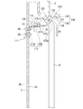
- FIG. 17 is a schematic configuration diagram of the lock rod 9 in the third modification.
- the lock rod 9 may have a sublock rod 109 formed so as to project from the outer peripheral surface near the tip (the other end).
- the sublock rod 109 is formed so as to protrude from the lock rod 9 so as to avoid interference with the pressed plates 26 and 126 of the first embodiment and the second embodiment.
- the lock rod 9 is operated in conjunction with the operation of the handle unit 4 .
- the present invention is not limited to this, and the lock rod 9 may be operated independently.
- a pressing portion capable of pressing the pressed plates 26 and 126 may be provided instead of the lock rod 9, a pressing portion capable of pressing the pressed plates 26 and 126 may be provided. In these cases, the lock rod 9 and the pressing portion are configured to be able to operate from the outside of the door 3 with the door 3 closed.
- hooks 12 and 112 are provided on the housing 2 and the lock protrusions 11 and 111 are provided on the door 3 .
- the present invention is not limited to this, and hooks 12 and 112 may be provided on the door 3 and lock protrusions 11 and 111 may be provided on the housing 2.
- the control panels 1, 101 include lock mechanisms 5, 105.
- the hooks 12, 112 of the locking mechanisms 5, 105 the hooks 12, 112 arranged at the upper ends are normally not subject to external force, and the engaging portions 19, 119 are normally raised upward to lock the convex portion 11. , 111 is disengaged.
- the hooks 12, 112 arranged at the lower end are normally in a state in which the engaging portions 19, 119 are disengaged from the downward lock convex portions 11, 111, to which an external force is not applied.
- the hooks 12 and 112 have a pressed plate 26 and 126 pressed by a lock rod 9 different from the hooks 12 and 112, and engaging pieces 22 and 122.
- the lock mechanisms 5, 105 can be configured with such a simple structure. Further, while satisfying the explosion-proof function of the control panels 1, 101, the opening / closing work of the door 3 can be simplified.
Abstract
A lock mechanism according to one embodiment comprises an engagement part, a hook, and a pressing part. The engagement part is provided to one of a housing and a door for opening/closing a housing opening in the housing. The hook is provided to the other of the housing and the door so as to be rotatable around a rotation axis, is capable of engaging with the engagement part, and is normally disengaged from the engagement part by the weight of the hook. The pressing part is provided separately from the hook and presses the hook. In addition, the hook has, on opposite sides of the rotation axis: a hook-side engagement part that engages with the engagement part; and a hook-side pressing part that engages the engagement part and the hook-side engagement part by being pressed by the pressing part.
Description
本発明の実施形態は、ロック機構に関する。
An embodiment of the present invention relates to a locking mechanism.
例えば、電力変換システム等の回路が収納された制御盤は、開口部を有する箱状の筐体と、この筐体の開口部を閉塞する扉と、を有している。扉を閉じている際は、扉に設けられているハンドルを回すことで、扉と筐体とが係合されて扉の閉状態が維持される。
For example, a control panel in which a circuit such as a power conversion system is housed has a box-shaped housing having an opening and a door that closes the opening of the housing. When the door is closed, by turning the handle provided on the door, the door and the housing are engaged and the closed state of the door is maintained.
ところで、大規模な電力変換システムは、回路に所定以上の大きな電力が流れ得る。このような場合、制御盤の筐体内でアークフラッシュ等が発生する可能性がある。このアークフラッシュ等が発生した場合の衝撃で扉が不用意に開かないように、ハンドルとは別に防爆用としてロック機構を設けることが考えられる。
By the way, in a large-scale power conversion system, a large amount of power exceeding a predetermined value can flow in the circuit. In such a case, an arc flash or the like may occur in the housing of the control panel. It is conceivable to provide a lock mechanism for explosion proof separately from the handle so that the door will not be opened carelessly due to the impact when this arc flash or the like occurs.
例えば、扉のハンドルとは別の箇所(扉の上下や扉の四隅)を、ボルトを用いて筐体に締結固定することが考えられる。このような場合、扉を開閉するたびにボルトを締め付けたり緩めたりする必要があり、扉の開閉作業が煩わしいものとなる。
For example, it is conceivable to fasten and fix the parts other than the door handle (upper and lower parts of the door and the four corners of the door) to the housing using bolts. In such a case, it is necessary to tighten or loosen the bolt every time the door is opened or closed, which makes the opening and closing work of the door troublesome.
扉に、ハンドルとは別にロック機構を設けることが考えられる。ロック機構としては、例えば回転軸線回りに回転するフックと、フックに係合する係合部と、フックの係合部への係合状態又は係合解除状態を維持するスプリングと、を備えたものがある。
しかしながら、上記のようなロック機構は構造が複雑でありコストが嵩む可能性があった。ハンドルと別にロック機構を設けると、ハンドルの開閉作業に加えてロック機構の係合、解除作業を行うことになる。このため、結局扉の開閉作業が煩わしいものとなる可能性があった。 It is conceivable to provide a lock mechanism on the door separately from the handle. The locking mechanism includes, for example, a hook that rotates around the axis of rotation, an engaging portion that engages with the hook, and a spring that maintains the engaged or disengaged state of the hook with the engaged portion. There is.
However, the lock mechanism as described above has a complicated structure and may be costly. If a lock mechanism is provided separately from the handle, the lock mechanism is engaged and disengaged in addition to the opening and closing work of the handle. For this reason, the opening and closing work of the door may become troublesome in the end.
本発明が解決しようとする課題は、防爆機能を満足しつつ構造を簡素化でき、かつ扉の開閉作業も簡素化できるロック機構を提供することである。
The problem to be solved by the present invention is to provide a lock mechanism capable of simplifying the structure while satisfying the explosion-proof function and also simplifying the opening and closing work of the door.
実施形態のロック機構は、係合部と、フックと、押圧部と、を備える。係合部は、筐体及び筐体の筐体開口部を開閉する扉のいずれか一方に設けられる。フックは、筐体及び扉のいずれか他方に回転軸線回りに回転可能に設けられ、係合部と係合可能、かつ自重により係合部との係合が常時解除されている。押圧部は、フックとは別に設けられ、フックを押圧する。また、フックは、回転軸線を挟んで係合部と係合されるフック側係合部と、押圧部によって押圧されることにより、係合部とフック側係合部とを係合させるフック側押圧部と、を有する。
The locking mechanism of the embodiment includes an engaging portion, a hook, and a pressing portion. The engaging portion is provided on either the housing or the door that opens and closes the housing opening of the housing. The hook is rotatably provided on either the housing or the door around the rotation axis, is engageable with the engaging portion, and is always disengaged from the engaging portion by its own weight. The pressing portion is provided separately from the hook and presses the hook. Further, the hook has a hook side engaging portion that is engaged with the engaging portion across the rotation axis, and a hook side that engages the engaging portion and the hook side engaging portion by being pressed by the pressing portion. It has a pressing portion and.
以下、実施形態のロック機構を、図面を参照して説明する。
Hereinafter, the locking mechanism of the embodiment will be described with reference to the drawings.
[第1実施形態]
図1は、例えば電力変換システム等の回路が収納された制御盤1の斜視図である。
制御盤1は、前面2aに開口部(請求項における筐体開口部の一例)2bを有する箱状の筐体2と、筐体2の開口部2bを開閉する扉3と、扉3に設けられたハンドルユニット4と、筐体2と扉3とに設けられたロック機構5と、を備える。以下の説明では、制御盤1を設置した状態での上下方向を単に上下方向、制御盤1を設置した状態での水平方向を単に水平方向と称して説明する。 [First Embodiment]
FIG. 1 is a perspective view of a control panel 1 in which a circuit such as a power conversion system is housed.
The control panel 1 is provided in a box-shaped housing 2 having an opening (an example of a housing opening in the claim) 2b on the front surface 2a, a door 3 for opening and closing the opening 2b of the housing 2, and a door 3. The handle unit 4 is provided, and the lock mechanism 5 provided on the housing 2 and the door 3 is provided. In the following description, the vertical direction with the control panel 1 installed is simply referred to as a vertical direction, and the horizontal direction with the control panel 1 installed is simply referred to as a horizontal direction.
図1は、例えば電力変換システム等の回路が収納された制御盤1の斜視図である。
制御盤1は、前面2aに開口部(請求項における筐体開口部の一例)2bを有する箱状の筐体2と、筐体2の開口部2bを開閉する扉3と、扉3に設けられたハンドルユニット4と、筐体2と扉3とに設けられたロック機構5と、を備える。以下の説明では、制御盤1を設置した状態での上下方向を単に上下方向、制御盤1を設置した状態での水平方向を単に水平方向と称して説明する。 [First Embodiment]
FIG. 1 is a perspective view of a control panel 1 in which a circuit such as a power conversion system is housed.
The control panel 1 is provided in a box-
筐体2は上下方向に長く形成されている。扉3は、筐体2の開口部2bにおける水平方向の一側に設けられた図示しない回転支持部材を介して回転可能に支持されている。扉3の回転支持部材とは反対側の一側に、ハンドルユニット4及びロック機構5が設けられている。
The housing 2 is formed long in the vertical direction. The door 3 is rotatably supported via a rotation support member (not shown) provided on one side in the horizontal direction of the opening 2b of the housing 2. A handle unit 4 and a lock mechanism 5 are provided on one side of the door 3 opposite to the rotation support member.
図2は、ハンドルユニット4を扉3の裏面3a側からみた斜視図である。
図2に示すように、ハンドルユニット4は、扉3の上下方向中央に設けられている。ハンドルユニット4は、扉3の表面3b側に設けられた図示しないハンドルと、扉3の裏面3a側に設けられた支持体6と、支持体6に回転自在に支持されている係合片8と、扉3を貫通してこの扉3と支持体6とに回転自在に支持されているとともに、図示しないハンドルと係合片8とを連結するハンドル回転軸7と、を備えている。 FIG. 2 is a perspective view of thehandle unit 4 as viewed from the back surface 3a side of the door 3.
As shown in FIG. 2, thehandle unit 4 is provided at the center of the door 3 in the vertical direction. The handle unit 4 includes a handle (not shown) provided on the front surface 3b side of the door 3, a support 6 provided on the back surface 3a side of the door 3, and an engaging piece 8 rotatably supported by the support 6. A handle rotating shaft 7 that penetrates the door 3 and is rotatably supported by the door 3 and the support 6 and connects the handle and the engaging piece 8 (not shown) is provided.
図2に示すように、ハンドルユニット4は、扉3の上下方向中央に設けられている。ハンドルユニット4は、扉3の表面3b側に設けられた図示しないハンドルと、扉3の裏面3a側に設けられた支持体6と、支持体6に回転自在に支持されている係合片8と、扉3を貫通してこの扉3と支持体6とに回転自在に支持されているとともに、図示しないハンドルと係合片8とを連結するハンドル回転軸7と、を備えている。 FIG. 2 is a perspective view of the
As shown in FIG. 2, the
支持体6は、上下方向に長い板状に形成されている。支持体6の長手方向中央に、ハンドル回転軸7が連結されている。
係合片8は、ハンドル回転軸7を介して図示しないハンドルと一体となって回転する。 Thesupport 6 is formed in the shape of a plate long in the vertical direction. A handle rotation shaft 7 is connected to the center of the support 6 in the longitudinal direction.
Theengaging piece 8 rotates integrally with a handle (not shown) via the handle rotation shaft 7.
係合片8は、ハンドル回転軸7を介して図示しないハンドルと一体となって回転する。 The
The
係合片8は、扉3を閉めて図示しないハンドルをロックした状態(以下、ハンドルロック状態という)で、支持体6の短手方向の端面から筐体2における開口部2bの周縁に向かって突出する。これにより、係合片8は、ハンドルロック状態で、筐体2の開口部2bの周縁と係合される(以下、係合片8の係合状態という)。また、係合片8は、扉3を開ける際にハンドルロック状態を解除するように図示しないハンドルを回転させると、支持体6内に収納される。これにより、係合片8は、筐体2における開口部2bの周縁との係合が解除される(以下、係合片8の係合解除状態という)。
The engaging piece 8 is in a state where the door 3 is closed and a handle (not shown) is locked (hereinafter referred to as a handle locked state), from the end surface of the support 6 in the lateral direction toward the peripheral edge of the opening 2b in the housing 2. Protrude. As a result, the engaging piece 8 is engaged with the peripheral edge of the opening 2b of the housing 2 in the handle locked state (hereinafter, referred to as the engaged state of the engaging piece 8). Further, the engaging piece 8 is housed in the support 6 when a handle (not shown) is rotated so as to release the handle locked state when the door 3 is opened. As a result, the engaging piece 8 is disengaged from the peripheral edge of the opening 2b in the housing 2 (hereinafter, referred to as the disengaging state of the engaging piece 8).
また、支持体6の長手方向両端には、ロック棒(請求項における押圧部の一例)9の一端が上下方向に沿ってスライド移動自在に支持されている。2つのロック棒9のうち、一方のロック棒9は、支持体6から扉3の上部に至る間に上下方向に沿って延びている。2つのロック棒9のうち、他方のロック棒9は、支持体6から扉3の下部に至る間に上下方向に沿って延びている。各ロック棒9の他端は、扉3の裏面3aにおける上部と下部とに設けられたガイド部10に、スライド移動自在に支持されている。
Further, at both ends of the support 6 in the longitudinal direction, one end of a lock rod (an example of a pressing portion in the claim) 9 is supported so as to be slidable and slidable along the vertical direction. Of the two lock rods 9, one lock rod 9 extends in the vertical direction from the support 6 to the upper part of the door 3. Of the two lock bars 9, the other lock bar 9 extends in the vertical direction from the support 6 to the lower part of the door 3. The other end of each lock rod 9 is slidably supported by guide portions 10 provided at the upper and lower portions of the back surface 3a of the door 3.
各ロック棒9は、係合片8(図示しないハンドル)の回転に伴い、上下方向にスライド移動される。より具体的には、係合片8の係合解除状態では、2つのロック棒9は、扉3の上下方向中央寄りに縮退されている(図2における矢印Y1参照)。これに対し、係合片8の係合状態では、2つのロック棒9は、扉3の上下方向に向かって突出されている(図2における矢印Y2参照)。このような2つのロック棒9は、それぞれロック機構5を動作させる。
Each lock rod 9 is slid up and down as the engaging piece 8 (handle not shown) rotates. More specifically, in the disengaged state of the engaging piece 8, the two lock rods 9 are retracted toward the center in the vertical direction of the door 3 (see arrow Y1 in FIG. 2). On the other hand, in the engaged state of the engaging piece 8, the two lock rods 9 are projected in the vertical direction of the door 3 (see arrow Y2 in FIG. 2). Each of these two lock rods 9 operates the lock mechanism 5.
ロック機構5は、筐体2及び扉3の上下両端部で、かつ対応するロック棒9の他端に近接配置されている。筐体2及び扉3の上下両端部に設けられた2つのロック機構5は、上下方向で互いに逆さまの向きで配置されており、構造は同一である。このため、以下の説明では、2つのロック機構5のうち、筐体2及び扉3の上端部に設けられたロック機構5について説明し、必要に応じて筐体2及び扉3の下端部に設けられたロック機構5について説明する。
The lock mechanism 5 is arranged at both upper and lower ends of the housing 2 and the door 3 and close to the other ends of the corresponding lock rods 9. The two lock mechanisms 5 provided at the upper and lower ends of the housing 2 and the door 3 are arranged upside down in the vertical direction, and have the same structure. Therefore, in the following description, of the two lock mechanisms 5, the lock mechanism 5 provided at the upper end portion of the housing 2 and the door 3 will be described, and if necessary, the lower end portion of the housing 2 and the door 3 will be described. The provided lock mechanism 5 will be described.
ロック機構5は、扉3の裏面3aに設けられたロック凸部(請求項における凸部の一例)11と、筐体2の開口部2bの周縁に設けられたフック12と、を備えている。
The lock mechanism 5 includes a lock convex portion (an example of the convex portion in the claim) 11 provided on the back surface 3a of the door 3 and a hook 12 provided on the peripheral edge of the opening 2b of the housing 2. ..
図3は、ロック凸部11の側面図である。図4は、ロック凸部11の正面図である。
図3、図4に示すように、ロック凸部11は、扉3の裏面3aに固定されるベース部13と、ベース部13から突出する段付き軸部17と、を有している。 FIG. 3 is a side view of the lockconvex portion 11. FIG. 4 is a front view of the lock convex portion 11.
As shown in FIGS. 3 and 4, the lockconvex portion 11 has a base portion 13 fixed to the back surface 3a of the door 3 and a stepped shaft portion 17 protruding from the base portion 13.
図3、図4に示すように、ロック凸部11は、扉3の裏面3aに固定されるベース部13と、ベース部13から突出する段付き軸部17と、を有している。 FIG. 3 is a side view of the lock
As shown in FIGS. 3 and 4, the lock
ベース部13は、扉3の裏面3aをみて水平方向に長い長方形の板状の部材である。ベース部13の四隅には、雌ネジ部13aが形成されている。扉3の雌ネジ部13aに対応する箇所には、貫通孔27が形成されている。この貫通孔27に、扉3の表面3b側からボルト28を挿入し、このボルト28を雌ネジ部13aに螺合させることにより、扉3の裏面3aにベース部13が締結固定される。
The base portion 13 is a rectangular plate-shaped member that is long in the horizontal direction when the back surface 3a of the door 3 is viewed. Female screw portions 13a are formed at the four corners of the base portion 13. A through hole 27 is formed at a portion of the door 3 corresponding to the female screw portion 13a. By inserting a bolt 28 into the through hole 27 from the front surface 3b side of the door 3 and screwing the bolt 28 into the female screw portion 13a, the base portion 13 is fastened and fixed to the back surface 3a of the door 3.
段付き軸部17は、ベース部13の法線方向(水平方向)に沿って突出している。つまり、段付き軸部17は、扉3の開閉方向に沿って突出されている。
段付き軸部17は、ベース部13から突出する第1軸部14と、第1軸部14のベース部13とは反対側(段付き軸部17の突出方向)の端部に一体成形され、第1軸部14よりも第1段差部14aを介して拡径された第2軸部15と、第2軸部15のベース部13とは反対側の端部に一体成形され、第2軸部15よりも第2段差部15aを介して拡径された第3軸部16と、を有する。 The steppedshaft portion 17 projects along the normal direction (horizontal direction) of the base portion 13. That is, the stepped shaft portion 17 projects along the opening / closing direction of the door 3.
The steppedshaft portion 17 is integrally formed with the first shaft portion 14 protruding from the base portion 13 and the end portion of the first shaft portion 14 on the opposite side of the base portion 13 (protruding direction of the stepped shaft portion 17). , The second shaft portion 15 whose diameter is expanded from the first shaft portion 14 via the first step portion 14a and the end portion of the second shaft portion 15 on the opposite side of the base portion 13 are integrally molded and formed into a second. It has a third shaft portion 16 whose diameter is expanded through the second step portion 15a rather than the shaft portion 15.
段付き軸部17は、ベース部13から突出する第1軸部14と、第1軸部14のベース部13とは反対側(段付き軸部17の突出方向)の端部に一体成形され、第1軸部14よりも第1段差部14aを介して拡径された第2軸部15と、第2軸部15のベース部13とは反対側の端部に一体成形され、第2軸部15よりも第2段差部15aを介して拡径された第3軸部16と、を有する。 The stepped
The stepped
第1軸部14の軸方向の長さL1よりも第2軸部15の軸方向の長さL2は短い。第2軸部15の軸方向の長さL2よりも第3軸部16の軸方向の長さL3は短い。第1軸部14及び第2軸部15は、円柱状に形成されており、第3軸部16は、ほぼ円板状に形成されている。
The axial length L2 of the second shaft portion 15 is shorter than the axial length L1 of the first shaft portion 14. The axial length L3 of the third shaft portion 16 is shorter than the axial length L2 of the second shaft portion 15. The first shaft portion 14 and the second shaft portion 15 are formed in a columnar shape, and the third shaft portion 16 is formed in a substantially disk shape.
図5は、フック12の側面図である。図6は、図5のA矢視図である。
図1、図5、図6に示すように、フック12は、筐体2における開口部2bの周縁に回転自在に設けられた回転軸(請求項における回転軸線の一例)18と、回転軸18を挟んで両側に設けられた係合部(請求項におけるフック側係合部の一例)19及び押圧部(請求項におけるフック側押圧部の一例)20と、を有する。
回転軸18は、筐体2の前面2aに沿って、かつ水平方向に沿って配置され、筐体2に回転自在に支持されている。 FIG. 5 is a side view of thehook 12. FIG. 6 is a view taken along the arrow A of FIG.
As shown in FIGS. 1, 5, and 6, thehook 12 includes a rotation shaft (an example of a rotation axis in the claims) 18 rotatably provided on the peripheral edge of the opening 2b in the housing 2, and a rotation shaft 18. It has an engaging portion (an example of a hook-side engaging portion in the claim) 19 and a pressing portion (an example of a hook-side pressing portion in the claim) 20 provided on both sides thereof.
Therotation shaft 18 is arranged along the front surface 2a of the housing 2 and along the horizontal direction, and is rotatably supported by the housing 2.
図1、図5、図6に示すように、フック12は、筐体2における開口部2bの周縁に回転自在に設けられた回転軸(請求項における回転軸線の一例)18と、回転軸18を挟んで両側に設けられた係合部(請求項におけるフック側係合部の一例)19及び押圧部(請求項におけるフック側押圧部の一例)20と、を有する。
回転軸18は、筐体2の前面2aに沿って、かつ水平方向に沿って配置され、筐体2に回転自在に支持されている。 FIG. 5 is a side view of the
As shown in FIGS. 1, 5, and 6, the
The
係合部19は、長方形の板状の部材を屈曲形成してなる。具体的には、係合部19は、回転軸18から一方向に沿って延びる支持板21と、支持板21の回転軸18とは反対側の端部から屈曲延出された係合片22と、を有する。支持板21と係合片22との間の角度は、ほぼ90°である。
The engaging portion 19 is formed by bending a rectangular plate-shaped member. Specifically, the engaging portion 19 is a support plate 21 extending from the rotating shaft 18 in one direction, and an engaging piece 22 bent and extended from an end portion of the support plate 21 opposite to the rotating shaft 18. And have. The angle between the support plate 21 and the engaging piece 22 is approximately 90 °.
係合片22には、面方向中央の大部分に開口部(請求項における第2開口部の一例)23が形成されている。開口部23は、係合片22の法線方向からみて円形状に形成されている。係合片22の支持板21とは反対側の先端部には、受入れ開口部(請求項における第1開口部の一例)24が形成されている。
The engagement piece 22 is formed with an opening (an example of the second opening in the claim) 23 at most of the center in the plane direction. The opening 23 is formed in a circular shape when viewed from the normal direction of the engaging piece 22. A receiving opening (an example of the first opening in the claims) 24 is formed at the tip of the engaging piece 22 on the opposite side of the support plate 21.
受入れ開口部24における係合片22の法線方向からみた幅W1は、開口部23の直径D1よりも小さい。より具体的には、開口部23の直径D1は、第2軸部15の軸径D2よりも大きく、かつ第3軸部16の軸径D3よりも小さい。受入れ開口部24の幅W1は、第1軸部14の軸径D4よりも大きく、第2軸部15の軸径D2よりも小さい。
The width W1 of the engaging piece 22 in the receiving opening 24 as seen from the normal direction is smaller than the diameter D1 of the opening 23. More specifically, the diameter D1 of the opening 23 is larger than the shaft diameter D2 of the second shaft portion 15 and smaller than the shaft diameter D3 of the third shaft portion 16. The width W1 of the receiving opening 24 is larger than the shaft diameter D4 of the first shaft portion 14 and smaller than the shaft diameter D2 of the second shaft portion 15.
回転軸18を挟んで係合部19とは反対側に設けられた押圧部20は、長方形の板状の部材を屈曲形成してなる。具体的には、押圧部20は、回転軸18から係合部19の支持板21と同一平面上で、かつ支持板21とは反対の他方向に沿って延びる延出片25と、延出片25の回転軸18とは反対側の端部から屈曲延出された被押圧板26と、を有する。被押圧板26の屈曲方向は、係合部19の係合片22の屈曲方向と逆方向である。延出片25と被押圧板26との間の角度は、支持板21と係合片22との間の角度よりも大きい。
The pressing portion 20 provided on the side opposite to the engaging portion 19 with the rotating shaft 18 interposed therebetween is formed by bending a rectangular plate-shaped member. Specifically, the pressing portion 20 is an extension piece 25 extending from the rotation shaft 18 on the same plane as the support plate 21 of the engagement portion 19 and extending in the other direction opposite to the support plate 21. It has a pressed plate 26 bent and extended from an end portion of the piece 25 opposite to the rotation shaft 18. The bending direction of the pressed plate 26 is opposite to the bending direction of the engaging piece 22 of the engaging portion 19. The angle between the extension piece 25 and the pressed plate 26 is larger than the angle between the support plate 21 and the engagement piece 22.
このように形成されたフック12は、係合部19が扉3の裏面3a側を向くように配置される。フック12は、扉3の裏面3a側を向いた状態で、回転軸18を中心に上下方向に揺動する。一方、押圧部20は、筐体2内側を向いた状態で、回転軸18を中心に上下方向に揺動する。
The hook 12 thus formed is arranged so that the engaging portion 19 faces the back surface 3a side of the door 3. The hook 12 swings in the vertical direction about the rotation shaft 18 while facing the back surface 3a side of the door 3. On the other hand, the pressing portion 20 swings in the vertical direction about the rotation shaft 18 while facing the inside of the housing 2.
ここで、筐体2の上下両端部に配置された2つのフック12のうち、上端部に配置されたフック12は、係合部19の重量よりも押圧部20の重量が重くなるように形成されている。下端部に配置されたフック12は、押圧部20の重量よりも係合部19の重量が重くなるように形成されている。このため、上端部に配置されたフック12は、外力のかからない通常では、フック12の自重により押圧部20が下向きに、かつ係合部19が上向きに起き上がる。下端部に配置されたフック12は、外力のかからない通常では、フック12の自重により係合部19が下向きに、かつ押圧部20が上向きに起き上がる。
Here, of the two hooks 12 arranged at the upper and lower ends of the housing 2, the hook 12 arranged at the upper end is formed so that the weight of the pressing portion 20 is heavier than the weight of the engaging portion 19. Has been done. The hook 12 arranged at the lower end portion is formed so that the weight of the engaging portion 19 is heavier than the weight of the pressing portion 20. Therefore, in the hook 12 arranged at the upper end portion, normally, the pressing portion 20 rises downward and the engaging portion 19 rises upward due to the weight of the hook 12 without external force. The hook 12 arranged at the lower end portion normally raises the engaging portion 19 downward and the pressing portion 20 upward due to the weight of the hook 12 without external force.
これらの状態では、ハンドルロック状態が解除されている。そして、上端部に配置されたフック12では、係合部19における被押圧板26の真下に、ロック棒9の先端(他端)が位置されている。下端部に配置されたフック12では、係合部19における被押圧板26の真上に、ロック棒9の先端(他端)が位置されている。
In these states, the handle lock state is released. In the hook 12 arranged at the upper end portion, the tip end (the other end) of the lock rod 9 is positioned directly below the pressed plate 26 in the engaging portion 19. In the hook 12 arranged at the lower end portion, the tip end (the other end) of the lock rod 9 is positioned directly above the pressed plate 26 in the engaging portion 19.
筐体2における開口部2bの周縁を、係合部19との干渉を避けるように切り欠いてもよい。図1では、開口部2bの周縁を切り欠いて図示している。開口部2bの周縁を切り欠かない場合、係合部19は、開口部2bよりも前方(扉3側)に位置する。
The peripheral edge of the opening 2b in the housing 2 may be cut out so as to avoid interference with the engaging portion 19. In FIG. 1, the peripheral edge of the opening 2b is cut out and shown. When the peripheral edge of the opening 2b is not cut out, the engaging portion 19 is located in front of the opening 2b (on the door 3 side).
次に、図7から図10に基づいて、ロック機構5の動作について説明する。
図7から図10は、ロック機構5の動作説明図である。筐体2及び扉3の上下両端部に設けられた2つのロック機構5の動作は同一である。このため、以下の説明では、2つのロック機構5のうち、筐体2及び扉3の上端部に設けられたロック機構5について説明し、必要に応じて筐体2及び扉3の下端部に設けられたロック機構5について説明する。 Next, the operation of thelock mechanism 5 will be described with reference to FIGS. 7 to 10.
7 to 10 are operation explanatory views of thelock mechanism 5. The operations of the two lock mechanisms 5 provided at the upper and lower ends of the housing 2 and the door 3 are the same. Therefore, in the following description, of the two lock mechanisms 5, the lock mechanism 5 provided at the upper end portion of the housing 2 and the door 3 will be described, and if necessary, the lower end portion of the housing 2 and the door 3 will be described. The provided lock mechanism 5 will be described.
図7から図10は、ロック機構5の動作説明図である。筐体2及び扉3の上下両端部に設けられた2つのロック機構5の動作は同一である。このため、以下の説明では、2つのロック機構5のうち、筐体2及び扉3の上端部に設けられたロック機構5について説明し、必要に応じて筐体2及び扉3の下端部に設けられたロック機構5について説明する。 Next, the operation of the
7 to 10 are operation explanatory views of the
図7に示すように、2つのロック機構5のうち、筐体2の上端部に配置されたフック12は、外力のかからない通常では、フック12の自重により押圧部20が下向きに、かつ係合部19が上向きに起き上がる。この状態から扉3を閉めてハンドルロック状態にすると、図8に示すように、ロック棒9が上下方向に向かってスライド移動する(図8における矢印Y3参照)。すると、ロック棒9の先端がフック12の被押圧板26を押し上げる。これにより、回転軸18を中心にフック12が回転される(図8における矢印Y4参照)。
As shown in FIG. 7, of the two locking mechanisms 5, the hook 12 arranged at the upper end of the housing 2 is normally engaged with the pressing portion 20 downward due to the weight of the hook 12 without external force. Part 19 gets up upward. When the door 3 is closed and the handle is locked from this state, the lock rod 9 slides in the vertical direction as shown in FIG. 8 (see arrow Y3 in FIG. 8). Then, the tip of the lock rod 9 pushes up the pressed plate 26 of the hook 12. As a result, the hook 12 is rotated around the rotation shaft 18 (see arrow Y4 in FIG. 8).
すると、フック12の係合部19が下がり、扉3に設けられたロック凸部11にフック12が係合される。具体的には、扉3が閉じ、かつフック12の係合部19が下がった状態では、フック12の係合片22の位置にロック凸部11の第1軸部14が位置されている。係合片22における受け入れ開口部24の幅W1は、第1軸部14の軸径D4よりも大きい。このため、フック12の係合部19が下がると、ロック凸部11の第1軸部14が係合片22の受け入れ開口部24を通過し、さらに係合片22の開口部23に第1軸部14が位置される。以下、このような状態をフック12の係合予備状態という。フック12の係合予備状態では、ハンドルロック状態である。
Then, the engaging portion 19 of the hook 12 is lowered, and the hook 12 is engaged with the lock convex portion 11 provided on the door 3. Specifically, when the door 3 is closed and the engaging portion 19 of the hook 12 is lowered, the first shaft portion 14 of the lock convex portion 11 is positioned at the position of the engaging piece 22 of the hook 12. The width W1 of the receiving opening 24 in the engaging piece 22 is larger than the shaft diameter D4 of the first shaft portion 14. Therefore, when the engaging portion 19 of the hook 12 is lowered, the first shaft portion 14 of the lock convex portion 11 passes through the receiving opening 24 of the engaging piece 22, and is further inserted into the opening 23 of the engaging piece 22. The shaft portion 14 is positioned. Hereinafter, such a state is referred to as an engagement preliminary state of the hook 12. In the pre-engagement state of the hook 12, the handle is locked.
次に、フック12の係合予備状態から、例えば筐体2内でアークフラッシュ等が発生した場合について説明する。
図9に示すように、筐体2内でアークフラッシュ等が発生すると、この衝撃により、扉3が内部から押圧されて開こうとする(図9における矢印Y5参照)。この際、扉3と一体となってロック凸部11が外側へと移動される。 Next, a case where an arc flash or the like is generated in thehousing 2 from the pre-engagement state of the hook 12 will be described.
As shown in FIG. 9, when an arc flash or the like is generated in thehousing 2, the door 3 is pressed from the inside by this impact and tries to open (see arrow Y5 in FIG. 9). At this time, the lock convex portion 11 is moved outward together with the door 3.
図9に示すように、筐体2内でアークフラッシュ等が発生すると、この衝撃により、扉3が内部から押圧されて開こうとする(図9における矢印Y5参照)。この際、扉3と一体となってロック凸部11が外側へと移動される。 Next, a case where an arc flash or the like is generated in the
As shown in FIG. 9, when an arc flash or the like is generated in the
ここで、フック12の係合片22における開口部23の直径D1は、第2軸部15の軸径D2よりも大きく、かつ第3軸部16の軸径D3よりも小さい。このため、扉3と一体となってロック凸部11が外側へ移動されると、係合片22の開口部23に第2軸部15が嵌り、係合片22に第3軸部16が突き当たる。この状態で、ロック凸部11にフック12が完全に係合される。以下、このような状態をフック12の係合状態という。これにより、ロック凸部11の外側への移動が規制される。ロック凸部11の外側への移動が規制されることにより、扉3の開方向への移動も規制される。
Here, the diameter D1 of the opening 23 in the engaging piece 22 of the hook 12 is larger than the shaft diameter D2 of the second shaft portion 15 and smaller than the shaft diameter D3 of the third shaft portion 16. Therefore, when the lock convex portion 11 is moved outward together with the door 3, the second shaft portion 15 fits into the opening 23 of the engaging piece 22, and the third shaft portion 16 is fitted to the engaging piece 22. bump into. In this state, the hook 12 is completely engaged with the lock protrusion 11. Hereinafter, such a state is referred to as an engaged state of the hook 12. This restricts the outward movement of the lock protrusion 11. By restricting the movement of the lock protrusion 11 to the outside, the movement of the door 3 in the opening direction is also restricted.
係合片22における受入れ開口部24の幅W1は、第2軸部15の軸径D2よりも小さい。このため、係合片22の開口部23に第2軸部15が嵌った状態では、例えば筐体2内でアークフラッシュ等が発生した際の衝撃で、フック12の係合部19が起き上がろうとすることが阻止される。つまり、フック12の係合状態の解除が阻止される。
The width W1 of the receiving opening 24 in the engaging piece 22 is smaller than the shaft diameter D2 of the second shaft portion 15. Therefore, in a state where the second shaft portion 15 is fitted in the opening 23 of the engaging piece 22, for example, the engaging portion 19 of the hook 12 tries to rise due to an impact when an arc flash or the like occurs in the housing 2. Is blocked. That is, the disengagement of the hook 12 from the engaged state is prevented.
このように、係合片22における開口部23の周囲(図6における斜線部参照)は、ロック凸部11からの軸方向(ロック凸部11の突出方向)への抜けを規制する第1規制部31として機能する。係合片22における受入れ開口部24の周囲(図6における斜線部参照)は、ロック凸部11からの係合解除方向(ロック凸部11の突出方向と交差する方向)への抜けを規制する第2規制部32として機能する。
As described above, the circumference of the opening 23 in the engaging piece 22 (see the shaded portion in FIG. 6) is the first regulation that regulates the escape from the lock convex portion 11 in the axial direction (the protruding direction of the lock convex portion 11). It functions as a unit 31. The periphery of the receiving opening 24 in the engaging piece 22 (see the shaded portion in FIG. 6) regulates the engagement release direction from the lock convex portion 11 (the direction intersecting the protruding direction of the lock convex portion 11). It functions as the second regulation unit 32.
ところで、フック12の係合状態では、例えば筐体2内でアークフラッシュ等が発生した際の衝撃で、扉3が変形したりロック棒9が変形したりしてフック12の係合状態を解除できない可能性がある。
ここで、ロック凸部11は、扉3の表面3b側から挿入されたボルト28により扉3に締結固定されている。このため、図10に示すように、ボルト28を扉3の表面3b側から緩めて取り外すことにより、扉3からロック凸部11を取り外すことができる。これにより、扉3を開くことができる。 By the way, in the engaged state of thehook 12, for example, the door 3 is deformed or the lock rod 9 is deformed by the impact when an arc flash or the like occurs in the housing 2, and the engaged state of the hook 12 is released. It may not be possible.
Here, the lockconvex portion 11 is fastened and fixed to the door 3 by a bolt 28 inserted from the surface 3b side of the door 3. Therefore, as shown in FIG. 10, the lock convex portion 11 can be removed from the door 3 by loosening and removing the bolt 28 from the surface 3b side of the door 3. As a result, the door 3 can be opened.
ここで、ロック凸部11は、扉3の表面3b側から挿入されたボルト28により扉3に締結固定されている。このため、図10に示すように、ボルト28を扉3の表面3b側から緩めて取り外すことにより、扉3からロック凸部11を取り外すことができる。これにより、扉3を開くことができる。 By the way, in the engaged state of the
Here, the lock
このように、上述の第1実施形態における制御盤1は、上下両端部に設けられたロック機構5を備える。ロック機構5は、扉3に設けられたロック凸部11と、筐体2に設けられロック凸部11と係合可能なフック12と、を備える。2つのフック12のうち、上端部に配置されたフック12は、外力のかからない通常では、係合部19が上向きに起き上ったロック凸部11に対する係合解除状態となる。2つのフック12のうち、下端部に配置されたフック12は、外力のかからない通常では、係合部19が下向きのロック凸部11に対する係合解除状態となる。そして、フック12は、このフック12とは別のロック棒9に押圧される被押圧板26と、係合片22と、を有する。ロック棒9によって被押圧板26が押圧されると、ロック凸部11に係合片22が係合される。このような簡素な構造でロック機構5を構成できる。また、ハンドルユニット4と連動してロック機構5を動作させることができるので、制御盤1の防爆機能を満足しつつ、扉3の開閉作業も簡素化できる。
As described above, the control panel 1 in the above-mentioned first embodiment includes lock mechanisms 5 provided at both upper and lower ends. The lock mechanism 5 includes a lock convex portion 11 provided on the door 3 and a hook 12 provided on the housing 2 and capable of engaging with the lock convex portion 11. Of the two hooks 12, the hook 12 arranged at the upper end is normally in a disengaged state with respect to the lock convex portion 11 in which the engaging portion 19 is raised upward and no external force is applied. Of the two hooks 12, the hook 12 arranged at the lower end is normally in a disengaged state with the engaging portion 19 facing downward to the lock convex portion 11 without an external force. The hook 12 has a pressed plate 26 pressed by a lock rod 9 different from the hook 12, and an engaging piece 22. When the pressed plate 26 is pressed by the lock rod 9, the engaging piece 22 is engaged with the lock convex portion 11. The lock mechanism 5 can be configured with such a simple structure. Further, since the lock mechanism 5 can be operated in conjunction with the handle unit 4, the opening and closing work of the door 3 can be simplified while satisfying the explosion-proof function of the control panel 1.
ロック凸部11は、第1軸部14、第2軸部15、及び第3軸部16からなる段付き軸部17を有する。係合片22は、開口部23及び受入れ開口部24を形成して第1規制部31及び第2規制部32を有する。第1規制部31によって、ロック凸部11からの軸方向への抜けを規制できる。第2規制部32によって、ロック凸部11からの係合解除方向への抜けを規制できる。このため、ロック機構5によって、制御盤1の防爆機能を確実に満足できる。
The lock convex portion 11 has a stepped shaft portion 17 including a first shaft portion 14, a second shaft portion 15, and a third shaft portion 16. The engaging piece 22 forms an opening 23 and a receiving opening 24, and has a first regulating portion 31 and a second regulating portion 32. The first regulating portion 31 can regulate the axial disconnection from the lock convex portion 11. The second regulating portion 32 can regulate the disconnection from the lock convex portion 11 in the disengagement direction. Therefore, the lock mechanism 5 can surely satisfy the explosion-proof function of the control panel 1.
ロック凸部11を第1軸部14、第2軸部15、及び第3軸部16を有する段付き状とすることにより、第1軸部14に係合片22が介在された状態と第2軸部15に係合片22の開口部23が嵌った状態の2つの状態を得ることができる。このため、制御盤1で何ら異常のない場合は、容易にロック機構5を解除できるので、使い勝手のよいロック機構5とすることができる。
By forming the lock convex portion 11 into a stepped shape having the first shaft portion 14, the second shaft portion 15, and the third shaft portion 16, the state in which the engaging piece 22 is interposed in the first shaft portion 14 and the second Two states can be obtained in which the opening 23 of the engaging piece 22 is fitted in the biaxial portion 15. Therefore, if there is no abnormality in the control panel 1, the lock mechanism 5 can be easily released, so that the lock mechanism 5 can be easily used.
扉3側にロック凸部11を設け、筐体2側にフック12を設けることにより、フック12を容易に配置できる。扉3側にフック12を設けようとすると、フック12の稼働スペースを確保するために扉3に加工が必要になる可能性がある。このため、扉3側にロック凸部11を設け、筐体2側にフック12を設けることにより、既存の制御盤1に容易にロック機構5を設けることが可能になる。
The hook 12 can be easily arranged by providing the lock convex portion 11 on the door 3 side and the hook 12 on the housing 2 side. If the hook 12 is to be provided on the door 3 side, the door 3 may need to be processed in order to secure an operating space for the hook 12. Therefore, by providing the lock convex portion 11 on the door 3 side and the hook 12 on the housing 2 side, the lock mechanism 5 can be easily provided on the existing control panel 1.
フック12の被押圧板26を押圧する手段として、ロック棒9を利用している。例えば既存の制御盤1には、ロック棒9は、筐体2の開口部2bの周縁と係合させるために用意されている場合が多い。このようなロック棒9を利用することにより、ロック機構5をさらに簡素化できる。また、既存の制御盤1にさらに容易にロック機構5を設けることが可能になる。
The lock rod 9 is used as a means for pressing the pressed plate 26 of the hook 12. For example, in the existing control panel 1, the lock rod 9 is often provided for engaging with the peripheral edge of the opening 2b of the housing 2. By using such a lock rod 9, the lock mechanism 5 can be further simplified. Further, the lock mechanism 5 can be more easily provided on the existing control panel 1.
ロック凸部11は、扉3の表面3b側から挿入されたボルト28により扉3に締結固定されている。このため、扉3の表面3b側から容易にロック凸部11を取り外すことができる。よって、係合片22の開口部23に第2軸部15が嵌った状態で、例えば筐体2内でアークフラッシュ等が発生した際の衝撃で扉3が変形したりロック棒9が変形したりした場合であっても、容易にロック機構5の係合を解除でき、扉3を開けることができる。
The lock convex portion 11 is fastened and fixed to the door 3 by a bolt 28 inserted from the surface 3b side of the door 3. Therefore, the lock convex portion 11 can be easily removed from the surface 3b side of the door 3. Therefore, in a state where the second shaft portion 15 is fitted in the opening 23 of the engaging piece 22, the door 3 is deformed or the lock rod 9 is deformed by an impact when an arc flash or the like occurs in the housing 2, for example. Even if it does, the lock mechanism 5 can be easily disengaged and the door 3 can be opened.
[第1変形例]
次に、図11に基づいて、第1変形例について説明する。
図11は、第1変形例を示すフック12の概略構成図である。
図11に示すように、変形例におけるフック12の押圧部20は、延出片25と被押圧板26との間の角度が上述の第1実施形態の延出片25と被押圧板26との間の角度よりも小さい。また、被押圧板26が屈曲形成されている。このため、フック12の係合予備状態では、筐体2の開口部2bの周縁に被押圧板26が係合される。 [First modification]
Next, a first modification will be described with reference to FIG.
FIG. 11 is a schematic configuration diagram of thehook 12 showing the first modification.
As shown in FIG. 11, in thepressing portion 20 of the hook 12 in the modified example, the angle between the extending piece 25 and the pressed plate 26 is the same as that of the extending piece 25 and the pressed plate 26 of the first embodiment described above. Less than the angle between. Further, the pressed plate 26 is bent and formed. Therefore, in the pre-engagement state of the hook 12, the pressed plate 26 is engaged with the peripheral edge of the opening 2b of the housing 2.
次に、図11に基づいて、第1変形例について説明する。
図11は、第1変形例を示すフック12の概略構成図である。
図11に示すように、変形例におけるフック12の押圧部20は、延出片25と被押圧板26との間の角度が上述の第1実施形態の延出片25と被押圧板26との間の角度よりも小さい。また、被押圧板26が屈曲形成されている。このため、フック12の係合予備状態では、筐体2の開口部2bの周縁に被押圧板26が係合される。 [First modification]
Next, a first modification will be described with reference to FIG.
FIG. 11 is a schematic configuration diagram of the
As shown in FIG. 11, in the
したがって、第1変形例によれば、前述の第1実施形態と同様の効果を奏する。また、扉3を閉じる際、筐体2に対して扉3が3箇所で係合される。つまり、ハンドルユニット4と、2つの被押圧板26と、により筐体2に対して扉3が係合される。このため、扉3の閉状態を強固に維持できるとともに、制御盤1の防爆機能をより向上できる。
Therefore, according to the first modification, the same effect as that of the above-mentioned first embodiment is obtained. Further, when the door 3 is closed, the door 3 is engaged with the housing 2 at three points. That is, the door 3 is engaged with the housing 2 by the handle unit 4 and the two pressed plates 26. Therefore, the closed state of the door 3 can be firmly maintained, and the explosion-proof function of the control panel 1 can be further improved.
上述の第1実施形態及び第1変形例では、フック12に係合される部材として、扉3にロック凸部11を設けた場合について説明した。しかしながらこれに限られるものではなく、フック12と係合可能な凸形状であればよい。この凸形状に対応するように、フック12に、凸形状に対する突出方向への抜けを規制する第1規制部31に相当する部位と、凸形状に対する突出方向と交差する方向への抜けを規制する第2規制部32に相当する部位を設けることが望ましい。
In the above-mentioned first embodiment and the first modification, a case where the lock convex portion 11 is provided on the door 3 as a member engaged with the hook 12 has been described. However, the present invention is not limited to this, and any convex shape that can be engaged with the hook 12 may be used. In order to correspond to this convex shape, the hook 12 is restricted to a portion corresponding to the first regulating portion 31 that regulates the protrusion in the protruding direction with respect to the convex shape, and the hook 12 is restricted from coming out in the direction intersecting the protruding direction with respect to the convex shape. It is desirable to provide a portion corresponding to the second regulation unit 32.
[第2実施形態]
次に、図12から図15に基づいて、第2実施形態について説明する。
図12は、第2実施形態における制御盤101のうち、特にロック機構105の詳細を示した概略構成図である。図12は、前述の第1実施形態における図7に対応している。以下の説明において、前述の第1実施形態と同一態様には同一符号を付して説明を省略する。 [Second Embodiment]
Next, the second embodiment will be described with reference to FIGS. 12 to 15.
FIG. 12 is a schematic configuration diagram showing the details of thelock mechanism 105 among the control panels 101 in the second embodiment. FIG. 12 corresponds to FIG. 7 in the above-mentioned first embodiment. In the following description, the same embodiments as those of the above-described first embodiment are designated by the same reference numerals and the description thereof will be omitted.
次に、図12から図15に基づいて、第2実施形態について説明する。
図12は、第2実施形態における制御盤101のうち、特にロック機構105の詳細を示した概略構成図である。図12は、前述の第1実施形態における図7に対応している。以下の説明において、前述の第1実施形態と同一態様には同一符号を付して説明を省略する。 [Second Embodiment]
Next, the second embodiment will be described with reference to FIGS. 12 to 15.
FIG. 12 is a schematic configuration diagram showing the details of the
図12に示すように、第2実施形態における制御盤101は、筐体2と、筐体2の開口部2bを開閉する扉3と、扉3に設けられたハンドルユニット4(図1等参照、図12では図示しない)と、筐体2と扉3とに設けられたロック機構105と、を備える点、ロック機構105は、筐体2及び扉3の上下両端部で、かつ対応するロック棒9の他端に近接配置されている点、筐体2及び扉3の上下両端部に設けられた2つのロック機構5は、上下方向で互いに逆さまの向きで配置されており、構造は同一である点等の基本的構成は、前述の第1実施形態と同様である。
As shown in FIG. 12, the control panel 101 in the second embodiment includes a housing 2, a door 3 for opening and closing the opening 2b of the housing 2, and a handle unit 4 provided in the door 3 (see FIG. 1 and the like). , Not shown in FIG. 12) and a locking mechanism 105 provided on the housing 2 and the door 3. The locking mechanism 105 is a corresponding lock at both upper and lower ends of the housing 2 and the door 3. The two lock mechanisms 5 provided at the upper and lower ends of the housing 2 and the door 3 are arranged upside down in the vertical direction, and have the same structure. The basic configuration is the same as that of the first embodiment described above.
第1実施形態と第2実施形態との相違点は、第1実施形態のロック機構5と第2実施形態のロック機構105とが異なる点にある。
以下の説明では、2つのロック機構105のうち、筐体2及び扉3の上端部に設けられたロック機構105について説明し、必要に応じて筐体2及び扉3の下端部に設けられたロック機構105について説明する。 The difference between the first embodiment and the second embodiment is that thelock mechanism 5 of the first embodiment and the lock mechanism 105 of the second embodiment are different.
In the following description, of the twolock mechanisms 105, the lock mechanism 105 provided at the upper end portions of the housing 2 and the door 3 will be described, and the lock mechanism 105 provided at the lower end portions of the housing 2 and the door 3 will be described as necessary. The lock mechanism 105 will be described.
以下の説明では、2つのロック機構105のうち、筐体2及び扉3の上端部に設けられたロック機構105について説明し、必要に応じて筐体2及び扉3の下端部に設けられたロック機構105について説明する。 The difference between the first embodiment and the second embodiment is that the
In the following description, of the two
ロック機構105は、扉3の裏面3aに設けられたロック凸部(請求項における凸部の一例)111と、筐体2の開口部2bの周縁に設けられたフック112と、を備えている。
ロック凸部111は、扉3の裏面3aに固定されるベース部113と、ベース部113から突出する軸部117と、を有している。 Thelock mechanism 105 includes a lock convex portion (an example of the convex portion in the claim) 111 provided on the back surface 3a of the door 3 and a hook 112 provided on the peripheral edge of the opening 2b of the housing 2. ..
The lockconvex portion 111 has a base portion 113 fixed to the back surface 3a of the door 3 and a shaft portion 117 protruding from the base portion 113.
ロック凸部111は、扉3の裏面3aに固定されるベース部113と、ベース部113から突出する軸部117と、を有している。 The
The lock
ベース部113は、扉3の裏面3aに当接される当接部113aと、当接部113aの上端から筐体2側に向かって、かつ水平方向に沿って屈曲延出された台座部113bと、を有する。当接部113aは、扉3の表面3bから挿入されるボルト28によって、扉3に締結固定されている。
The base portion 113 has a contact portion 113a that comes into contact with the back surface 3a of the door 3 and a pedestal portion 113b that is bent and extended from the upper end of the contact portion 113a toward the housing 2 side and along the horizontal direction. And have. The contact portion 113a is fastened and fixed to the door 3 by a bolt 28 inserted from the surface 3b of the door 3.
台座部113bの上面に、軸部117が上下方向に沿って突出されている。軸部117は、円柱状の軸部本体(請求項における第4軸部の一例)117aと、軸部本体117aの上端に一体成形され、軸部本体117aよりも段差部117cを介して拡径形成された円板状の頭部(請求項における第5軸部の一例)117bと、を有する。
A shaft portion 117 is projected along the vertical direction on the upper surface of the pedestal portion 113b. The shaft portion 117 is integrally formed with a columnar shaft portion main body (an example of the fourth shaft portion in the claim) 117a and the upper end of the shaft portion main body 117a, and has a larger diameter than the shaft portion main body 117a via a step portion 117c. It has a disk-shaped head formed (an example of the fifth shaft portion in the claim) 117b.
図13は、図12のB矢視図である。
図12、図13に示すように、フック112は、筐体2における開口部2bの周縁に回転自在に設けられた回転軸(請求項における回転軸線の一例)118と、回転軸118に回転自在に支持されている支持板133と、支持板133の一側133aから扉3側に向かって延出された係合部(請求項におけるフック側係合部の一例)119と、支持板133の一側133aから係合部119とは反対側に向かって延出された押圧部(請求項におけるフック側押圧部の一例)120と、を有する。フック112は、自重により支持板133の一側133aが下側に位置するように形成されている。支持板133の一側133aは、外力を受けない状態で水平方向に沿っている。 FIG. 13 is a view taken along the line B of FIG.
As shown in FIGS. 12 and 13, thehook 112 is rotatably provided on the peripheral edge of the opening 2b in the housing 2 and is rotatably provided on the rotation shaft (an example of the rotation axis in the claims) 118 and the rotation shaft 118. 119 of the support plate 133 supported by the support plate 133, an engaging portion extending from one side 133a of the support plate 133 toward the door 3 side (an example of the hook side engaging portion in the claims), and the support plate 133. It has a pressing portion (an example of the hook-side pressing portion in the claim) 120 extending from one side 133a toward the side opposite to the engaging portion 119. The hook 112 is formed so that one side 133a of the support plate 133 is located on the lower side due to its own weight. One side 133a of the support plate 133 runs in the horizontal direction without receiving an external force.
図12、図13に示すように、フック112は、筐体2における開口部2bの周縁に回転自在に設けられた回転軸(請求項における回転軸線の一例)118と、回転軸118に回転自在に支持されている支持板133と、支持板133の一側133aから扉3側に向かって延出された係合部(請求項におけるフック側係合部の一例)119と、支持板133の一側133aから係合部119とは反対側に向かって延出された押圧部(請求項におけるフック側押圧部の一例)120と、を有する。フック112は、自重により支持板133の一側133aが下側に位置するように形成されている。支持板133の一側133aは、外力を受けない状態で水平方向に沿っている。 FIG. 13 is a view taken along the line B of FIG.
As shown in FIGS. 12 and 13, the
係合部119は、長方形の板状の部材を屈曲形成してなる。具体的には、係合部119は、支持板133の一側133aに沿って延びる延出板121と、延出板121の支持板133とは反対側の端部から屈曲延出された係合片122と、を有する。係合片122は、支持板133の一側133aが下側に位置した状態で、斜め上方に延出されている。
The engaging portion 119 is formed by bending a rectangular plate-shaped member. Specifically, the engaging portion 119 is bent and extended from an extension plate 121 extending along one side 133a of the support plate 133 and an end portion of the extension plate 121 opposite to the support plate 133. It has a piece 122 and. The engaging piece 122 extends diagonally upward with one side 133a of the support plate 133 located on the lower side.
係合片122には、面方向中央の大部分に開口部(請求項における第4開口部の一例)123が形成されている。開口部123は、係合片22の法線方向からみて支持板133とは反対側が凸となる半円状に形成されている。開口部123の大きさは、軸部117の軸部本体117a及び頭部117bのいずれも通過可能な大きさである。
The engaging piece 122 is formed with an opening (an example of the fourth opening in the claim) 123 in most of the center in the plane direction. The opening 123 is formed in a semicircular shape in which the side opposite to the support plate 133 is convex when viewed from the normal direction of the engaging piece 22. The size of the opening 123 is such that both the shaft portion main body 117a and the head portion 117b of the shaft portion 117 can pass through.
開口部123の凸側の中央には、小開口部(請求項における第3開口部の一例)124が形成されている。小開口部124は、開口部123と連通されている。また、小開口部124の開口部123とは反対側の先端部は、係合片122の外側と貫通しておらず閉塞されている。小開口部124の大きさは、軸部117の軸部本体117aが通過可能、かつ頭部117bが通過不能な大きさである。
A small opening (an example of the third opening in the claim) 124 is formed in the center of the convex side of the opening 123. The small opening 124 communicates with the opening 123. Further, the tip of the small opening 124 on the opposite side of the opening 123 does not penetrate the outside of the engaging piece 122 and is closed. The size of the small opening 124 is such that the shaft body 117a of the shaft 117 can pass through and the head 117b cannot pass through.
支持板133の係合片122を挟んで係合部119とは反対側に設けられた押圧部120は、長方形の板状の部材を屈曲形成してなる。具体的には、押圧部120は、支持板133の一側133aに沿って延びる被押圧板126と、被押圧板126の支持板133とは反対側の端部から屈曲延出された返し板134と、を有する。被押圧板126と返し板134との間の角度は、ほぼ90°である。
The pressing portion 120 provided on the side opposite to the engaging portion 119 with the engaging piece 122 of the support plate 133 interposed therebetween is formed by bending a rectangular plate-shaped member. Specifically, the pressing portion 120 includes a pressed plate 126 extending along one side 133a of the support plate 133 and a return plate bent and extended from an end portion of the pressed plate 126 opposite to the support plate 133. It has 134 and. The angle between the pressed plate 126 and the return plate 134 is approximately 90 °.
このように形成されたフック12は、回転軸18を中心に係合部119が上下方向に揺動する形になる。そして、ハンドルロック状態が解除された状態では、被押圧板126の真下に、ロック棒9の先端(他端)が位置されている。下端部に配置されたフック112では、被押圧板126の真上に、ロック棒9の先端(他端)が位置されている。
The hook 12 thus formed has a shape in which the engaging portion 119 swings in the vertical direction around the rotation shaft 18. Then, in the state where the handle lock state is released, the tip end (the other end) of the lock rod 9 is positioned directly under the pressed plate 126. In the hook 112 arranged at the lower end portion, the tip end (the other end) of the lock rod 9 is positioned directly above the pressed plate 126.
次に、図12、図14、図15に基づいて、ロック機構105の動作について説明する。
図14、図15は、ロック機構105の動作説明図である。図15は、図13に対応している。筐体2及び扉3の上下両端部に設けられた2つのロック機構105の動作は同一である。このため、以下の説明では、2つのロック機構105のうち、筐体2及び扉3の上端部に設けられたロック機構105について説明し、必要に応じて筐体2及び扉3の下端部に設けられたロック機構105について説明する。 Next, the operation of thelock mechanism 105 will be described with reference to FIGS. 12, 14, and 15.
14 and 15 are operation explanatory views of thelock mechanism 105. FIG. 15 corresponds to FIG. The operations of the two lock mechanisms 105 provided at the upper and lower ends of the housing 2 and the door 3 are the same. Therefore, in the following description, of the two lock mechanisms 105, the lock mechanism 105 provided at the upper end portion of the housing 2 and the door 3 will be described, and if necessary, the lower end portion of the housing 2 and the door 3 will be described. The provided lock mechanism 105 will be described.
図14、図15は、ロック機構105の動作説明図である。図15は、図13に対応している。筐体2及び扉3の上下両端部に設けられた2つのロック機構105の動作は同一である。このため、以下の説明では、2つのロック機構105のうち、筐体2及び扉3の上端部に設けられたロック機構105について説明し、必要に応じて筐体2及び扉3の下端部に設けられたロック機構105について説明する。 Next, the operation of the
14 and 15 are operation explanatory views of the
図12に示すように、2つのロック機構105のうち、筐体2の上端部に配置されたフック112は、外力のかからない通常では、フック112の自重により支持板133の一側133aが下側に位置し、かつ係合片122が斜め上方に起き上がっている。この状態から扉3を閉めてハンドルロック状態にすると、図14に示すように、ロック棒9が上下方向に向かってスライド移動する(図14における矢印Y6参照)。すると、ロック棒9の先端がフック112の被押圧板126を押し上げる。これにより、回転軸118を中心にフック112が回転される(図14における矢印Y7参照)。
As shown in FIG. 12, of the two lock mechanisms 105, the hook 112 arranged at the upper end of the housing 2 is normally not subject to external force, and normally, one side 133a of the support plate 133 is on the lower side due to the weight of the hook 112. The engaging piece 122 rises diagonally upward. When the door 3 is closed and the handle is locked from this state, the lock rod 9 slides in the vertical direction as shown in FIG. 14 (see arrow Y6 in FIG. 14). Then, the tip of the lock rod 9 pushes up the pressed plate 126 of the hook 112. As a result, the hook 112 is rotated around the rotation shaft 118 (see arrow Y7 in FIG. 14).
すると、フック112の係合部119が下がり、扉3に設けられたロック凸部111にフック112が係合される。具体的には、扉3が閉じ、かつフック112の係合部119が下がった状態では、フック112の係合片122に形成されている開口部123の位置に、ロック凸部111の軸部117が位置されている。開口部123の大きさは、軸部117の軸部本体117a及び頭部117bのいずれも通過可能な大きさである。このため、フック112の係合部119が下がると、軸部117が開口部123を通過し、ロック凸部111の台座部113b上にフック112の係合片122が当接される。以下、このような状態をフック112の係合予備状態という。フック112の係合予備状態では、ハンドルロック状態である。
Then, the engaging portion 119 of the hook 112 is lowered, and the hook 112 is engaged with the lock convex portion 111 provided on the door 3. Specifically, when the door 3 is closed and the engaging portion 119 of the hook 112 is lowered, the shaft portion of the lock convex portion 111 is located at the position of the opening 123 formed in the engaging piece 122 of the hook 112. 117 is located. The size of the opening 123 is such that both the shaft portion main body 117a and the head portion 117b of the shaft portion 117 can pass through. Therefore, when the engaging portion 119 of the hook 112 is lowered, the shaft portion 117 passes through the opening 123, and the engaging piece 122 of the hook 112 is brought into contact with the pedestal portion 113b of the lock convex portion 111. Hereinafter, such a state is referred to as an engagement preliminary state of the hook 112. In the pre-engagement state of the hook 112, the handle is locked.
次に、フック12の係合予備状態から、例えば筐体2内でアークフラッシュ等が発生した場合について説明する。
図15に示すように、筐体2内でアークフラッシュ等が発生すると、この衝撃により、扉3が内部から押圧されて開こうとする(図15における矢印Y7参照)。この際、扉3と一体となってロック凸部111が外側へと移動される。 Next, a case where an arc flash or the like is generated in thehousing 2 from the pre-engagement state of the hook 12 will be described.
As shown in FIG. 15, when an arc flash or the like is generated in thehousing 2, the door 3 is pressed from the inside by this impact and tries to open (see arrow Y7 in FIG. 15). At this time, the lock convex portion 111 is moved outward together with the door 3.
図15に示すように、筐体2内でアークフラッシュ等が発生すると、この衝撃により、扉3が内部から押圧されて開こうとする(図15における矢印Y7参照)。この際、扉3と一体となってロック凸部111が外側へと移動される。 Next, a case where an arc flash or the like is generated in the
As shown in FIG. 15, when an arc flash or the like is generated in the
ここで、フック112の係合片122における小開口部124の大きさは、軸部117の軸部本体117aが通過可能な大きさである。このため、扉3と一体となってロック凸部111が外側へ移動されると、係合片122の小開口部124に軸部117の軸部本体117aが嵌り、小開口部124の先端部に軸部本体117aが突き当たる。この状態で、ロック凸部111にフック112が完全に係合される。以下、このような状態をフック112の係合状態という。これにより、ロック凸部111の外側への移動が規制される。ロック凸部111の外側への移動が規制されることにより、扉3の開方向への移動も規制される。
Here, the size of the small opening 124 in the engaging piece 122 of the hook 112 is a size that allows the shaft portion main body 117a of the shaft portion 117 to pass through. Therefore, when the lock convex portion 111 is moved outward together with the door 3, the shaft portion main body 117a of the shaft portion 117 is fitted into the small opening portion 124 of the engaging piece 122, and the tip portion of the small opening portion 124 is fitted. The shaft body 117a abuts against. In this state, the hook 112 is completely engaged with the lock protrusion 111. Hereinafter, such a state is referred to as an engaged state of the hook 112. This restricts the outward movement of the lock protrusion 111. By restricting the movement of the lock protrusion 111 to the outside, the movement of the door 3 in the opening direction is also restricted.
また、小開口部124の大きさは、軸部117の頭部117bが通過不能な大きさである。このため、係合片122の小開口部124に軸部本体117aが嵌った状態では、例えば筐体2内でアークフラッシュ等が発生した際の衝撃で、フック112の係合部119が起き上がろうとすることが阻止される。つまり、フック112の係合状態の解除が阻止される。
Further, the size of the small opening 124 is such that the head 117b of the shaft portion 117 cannot pass through. Therefore, in a state where the shaft portion main body 117a is fitted in the small opening 124 of the engaging piece 122, the engaging portion 119 of the hook 112 tries to rise due to an impact when an arc flash or the like occurs in the housing 2, for example. Is blocked. That is, the disengagement of the hook 112 from the engaged state is prevented.
このように、係合片122における小開口部124の周囲(図13における斜線部参照)は、ロック凸部111における軸部117からの軸方向(軸部117の突出方向)への抜けを規制する第1規制部131として機能する。また、小開口部124の周囲は、軸部117の突出方向と交差する方向への抜けを規制する第2規制部132として機能する(図13参照)。
したがって、上述の第2実施形態では、前述の第1実施形態と同様の効果を奏する。 As described above, the periphery of thesmall opening 124 in the engaging piece 122 (see the shaded portion in FIG. 13) restricts the lock convex portion 111 from coming off from the shaft portion 117 in the axial direction (protruding direction of the shaft portion 117). It functions as the first regulation unit 131. Further, the periphery of the small opening 124 functions as a second regulating portion 132 that regulates the escape of the shaft portion 117 in the direction intersecting the protruding direction (see FIG. 13).
Therefore, the above-mentioned second embodiment has the same effect as the above-mentioned first embodiment.
したがって、上述の第2実施形態では、前述の第1実施形態と同様の効果を奏する。 As described above, the periphery of the
Therefore, the above-mentioned second embodiment has the same effect as the above-mentioned first embodiment.
上述の第2実施形態では、フック112に係合される部材として、扉3にロック凸部111を設けた場合について説明した。しかしながらこれに限られるものではなく、フック112と係合可能な凸形状であればよい。この凸形状に対応するように、フック112に、凸形状に対する突出方向への抜けを規制する第1規制部131に相当する部位と、凸形状に対する突出方向と交差する方向への抜けを規制する第2規制部132に相当する部位を設けることが望ましい。
In the above-mentioned second embodiment, a case where the door 3 is provided with the lock convex portion 111 as a member engaged with the hook 112 has been described. However, the present invention is not limited to this, and any convex shape that can be engaged with the hook 112 may be used. In order to correspond to this convex shape, the hook 112 is restricted from the portion corresponding to the first restricting portion 131 that regulates the protrusion in the protruding direction with respect to the convex shape and the portion corresponding to the first restricting portion 131 that regulates the withdrawal in the direction intersecting the protruding direction with respect to the convex shape. It is desirable to provide a portion corresponding to the second regulation unit 132.
上述の第2実施形態において、被押圧板126の構成として前述の第1変形例の構成を採用してもよい。すなわち、ハンドルロック状態(フック12の係合状態)において、筐体2の開口部2bの周縁に被押圧板126が係合されるように構成してもよい。
In the above-mentioned second embodiment, the configuration of the above-mentioned first modification may be adopted as the configuration of the pressed plate 126. That is, in the handle locked state (engaged state of the hook 12), the pressed plate 126 may be configured to be engaged with the peripheral edge of the opening 2b of the housing 2.
[第2変形例及び第3変形例]
上述の第1変形例では、ハンドルロック状態(フック12の係合状態)において、筐体2の開口部2bの周縁に被押圧板26が係合される場合について説明した。しかしながらこれに限られるものではなく、ハンドルロック状態において筐体2の開口部2bの周縁にロック棒9を係合させるようにしてもよい。以下、具体的な例について説明する。 [Second modification and third modification]
In the above-mentioned first modification, the case where the pressedplate 26 is engaged with the peripheral edge of the opening 2b of the housing 2 in the handle locked state (engaged state of the hook 12) has been described. However, the present invention is not limited to this, and the lock rod 9 may be engaged with the peripheral edge of the opening 2b of the housing 2 in the handle locked state. A specific example will be described below.
上述の第1変形例では、ハンドルロック状態(フック12の係合状態)において、筐体2の開口部2bの周縁に被押圧板26が係合される場合について説明した。しかしながらこれに限られるものではなく、ハンドルロック状態において筐体2の開口部2bの周縁にロック棒9を係合させるようにしてもよい。以下、具体的な例について説明する。 [Second modification and third modification]
In the above-mentioned first modification, the case where the pressed
図16は、第2変形例におけるフック12,112の係合片22,122及びロック棒9の概略構成図である。
図16に示すように、ロック棒9は、第1棒部9aと、第1棒部9aの先端側にこの第1棒部9aよりも段差部9cを介して縮径形成された第2棒部9bと、を有してもよい。この場合、第1実施形態及び第2実施形態の被押圧板26,126に第1棒部9aを通過不能、かつ第2棒部9bを通過可能な貫通孔26a,126aを形成する。このように構成することで、ハンドルロック状態の際、ロック棒9の段差部9cによって被押圧板26,126が押し上げ(押し下げ)られる。 FIG. 16 is a schematic configuration diagram of the engaging pieces 22, 122 and the lock rod 9 of the hooks 12, 112 in the second modification.
As shown in FIG. 16, thelock rod 9 has a first rod portion 9a and a second rod formed on the tip end side of the first rod portion 9a via a stepped portion 9c rather than the first rod portion 9a. It may have a part 9b and. In this case, through holes 26a and 126a that cannot pass through the first rod portion 9a and can pass through the second rod portion 9b are formed in the pressed plates 26 and 126 of the first embodiment and the second embodiment. With this configuration, the pressed plates 26 and 126 are pushed up (pushed down) by the stepped portion 9c of the lock rod 9 when the handle is locked.
図16に示すように、ロック棒9は、第1棒部9aと、第1棒部9aの先端側にこの第1棒部9aよりも段差部9cを介して縮径形成された第2棒部9bと、を有してもよい。この場合、第1実施形態及び第2実施形態の被押圧板26,126に第1棒部9aを通過不能、かつ第2棒部9bを通過可能な貫通孔26a,126aを形成する。このように構成することで、ハンドルロック状態の際、ロック棒9の段差部9cによって被押圧板26,126が押し上げ(押し下げ)られる。 FIG. 16 is a schematic configuration diagram of the engaging
As shown in FIG. 16, the
第2棒部9bの長さは、ハンドルロック状態において筐体2の開口部2bの周縁に係合可能な長さである。
したがって、第2変形例によれば、前述の第1変形例と同様の効果を奏する。 The length of thesecond rod portion 9b is a length that can be engaged with the peripheral edge of the opening 2b of the housing 2 in the handle locked state.
Therefore, according to the second modification, the same effect as that of the first modification described above is obtained.
したがって、第2変形例によれば、前述の第1変形例と同様の効果を奏する。 The length of the
Therefore, according to the second modification, the same effect as that of the first modification described above is obtained.
図17は、第3変形例におけるロック棒9の概略構成図である。
図17に示すように、ロック棒9は、先端(他端)寄りの外周面から突出形成されたサブロック棒109を有してもよい。サブロック棒109は、第1実施形態及び第2実施形態の被押圧板26,126との干渉を避けるようにしてロック棒9よりも突出するように形成されている。 FIG. 17 is a schematic configuration diagram of thelock rod 9 in the third modification.
As shown in FIG. 17, thelock rod 9 may have a sublock rod 109 formed so as to project from the outer peripheral surface near the tip (the other end). The sublock rod 109 is formed so as to protrude from the lock rod 9 so as to avoid interference with the pressed plates 26 and 126 of the first embodiment and the second embodiment.
図17に示すように、ロック棒9は、先端(他端)寄りの外周面から突出形成されたサブロック棒109を有してもよい。サブロック棒109は、第1実施形態及び第2実施形態の被押圧板26,126との干渉を避けるようにしてロック棒9よりも突出するように形成されている。 FIG. 17 is a schematic configuration diagram of the
As shown in FIG. 17, the
このような構成のもと、ハンドルロック状態では、筐体2の開口部2bの周縁にサブロック棒109が係合される。
したがって、第3変形例によれば、前述の第1変形例と同様の効果を奏する。 Under such a configuration, in the handle locked state, thesublock rod 109 is engaged with the peripheral edge of the opening 2b of the housing 2.
Therefore, according to the third modification, the same effect as that of the first modification described above is obtained.
したがって、第3変形例によれば、前述の第1変形例と同様の効果を奏する。 Under such a configuration, in the handle locked state, the
Therefore, according to the third modification, the same effect as that of the first modification described above is obtained.
上述の各実施形態及び各変形例では、ハンドルユニット4の動作に連動させてロック棒9を動作させる場合について説明した。しかしながらこれに限られるものではなく、ロック棒9を独立して動作させるようにしてもよい。また、ロック棒9に代わって被押圧板26,126を押圧可能な押圧部を設けてもよい。これらの場合、扉3を閉めた状態でロック棒9や押圧部を扉3の外側から動作できるように構成する。
In each of the above-described embodiments and modifications, the case where the lock rod 9 is operated in conjunction with the operation of the handle unit 4 has been described. However, the present invention is not limited to this, and the lock rod 9 may be operated independently. Further, instead of the lock rod 9, a pressing portion capable of pressing the pressed plates 26 and 126 may be provided. In these cases, the lock rod 9 and the pressing portion are configured to be able to operate from the outside of the door 3 with the door 3 closed.
上述の第1実施形態及び第2実施形態では、筐体2にフック12,112を設け、扉3にロック凸部11,111を設けた場合について説明した。しかしながらこれに限られるものではなく、扉3にフック12,112を設け、筐体2にロック凸部11,111を設けてもよい。
In the above-mentioned first embodiment and the second embodiment, the case where the hooks 12 and 112 are provided on the housing 2 and the lock protrusions 11 and 111 are provided on the door 3 has been described. However, the present invention is not limited to this, and hooks 12 and 112 may be provided on the door 3 and lock protrusions 11 and 111 may be provided on the housing 2.
以上説明した少なくともひとつの実施形態によれば、制御盤1,101は、ロック機構5,105を備えている。ロック機構5,105の2つのフック12,112のうち、上端部に配置されたフック12,112は、外力のかからない通常では、係合部19,119が上向きに起き上ったロック凸部11,111に対する係合解除状態となる。2つのフック12,112のうち、下端部に配置されたフック12,112は、外力のかからない通常では、係合部19,119が下向きのロック凸部11,111に対する係合解除状態となる。そして、フック12,112は、このフック12,112とは別のロック棒9に押圧される被押圧板26,126と、係合片22,122と、を有する。ロック棒9によって被押圧板26,126が押圧されると、ロック凸部11,111に係合片22,122が係合される。このような簡素な構造でロック機構5,105を構成できる。また、制御盤1,101の防爆機能を満足しつつ、扉3の開閉作業も簡素化できる。
According to at least one embodiment described above, the control panels 1, 101 include lock mechanisms 5, 105. Of the two hooks 12, 112 of the locking mechanisms 5, 105, the hooks 12, 112 arranged at the upper ends are normally not subject to external force, and the engaging portions 19, 119 are normally raised upward to lock the convex portion 11. , 111 is disengaged. Of the two hooks 12, 112, the hooks 12, 112 arranged at the lower end are normally in a state in which the engaging portions 19, 119 are disengaged from the downward lock convex portions 11, 111, to which an external force is not applied. The hooks 12 and 112 have a pressed plate 26 and 126 pressed by a lock rod 9 different from the hooks 12 and 112, and engaging pieces 22 and 122. When the pressed plates 26 and 126 are pressed by the lock rod 9, the engaging pieces 22 and 122 are engaged with the lock protrusions 11 and 111. The lock mechanisms 5, 105 can be configured with such a simple structure. Further, while satisfying the explosion-proof function of the control panels 1, 101, the opening / closing work of the door 3 can be simplified.
本発明のいくつかの実施形態を説明したが、これらの実施形態は、例として提示したものであり、発明の範囲を限定することは意図していない。これら実施形態は、その他の様々な形態で実施されることが可能であり、発明の要旨を逸脱しない範囲で、種々の省略、置き換え、変更を行うことができる。これら実施形態やその変形は、発明の範囲や要旨に含まれると同様に、特許請求の範囲に記載された発明とその均等の範囲に含まれるものである。
Although some embodiments of the present invention have been described, these embodiments are presented as examples and are not intended to limit the scope of the invention. These embodiments can be implemented in various other embodiments, and various omissions, replacements, and changes can be made without departing from the gist of the invention. These embodiments and variations thereof are included in the scope of the invention described in the claims and the equivalent scope thereof, as are included in the scope and gist of the invention.
1,101…制御盤、2…筐体、2b…開口部(筐体開口部)、3…扉、4…ハンドルユニット(ハンドル)、5,105…ロック機構、9…ロック棒(押圧部、棒体)、11,111…ロック凸部(凸部)、12,112…フック、14…第1軸部、15…第2軸部、16…第3軸部、17…段付き軸部、18…回転軸、19,119…係合部(フック側係合部)、20,120…押圧部(フック側押圧部)、23…開口部(第2開口部)、24…受入れ開口部(第1開口部)、31,131…第1規制部、32,132…第2規制部、117…軸部、117a…軸部本体(第4軸部)、117b…頭部(第5軸部)、123…開口部(第4開口部)、124…小開口部(第3開口部)
1,101 ... Control panel, 2 ... Housing, 2b ... Opening (housing opening), 3 ... Door, 4 ... Handle unit (handle), 5,105 ... Lock mechanism, 9 ... Lock rod (pressing part, Rod body), 11,111 ... Lock convex part (convex part), 12,112 ... Hook, 14 ... 1st shaft part, 15 ... 2nd shaft part, 16 ... 3rd shaft part, 17 ... Stepped shaft part, 18 ... Rotating shaft, 19,119 ... Engaging part (hook side engaging part), 20,120 ... Pressing part (hook side pressing part), 23 ... Opening part (second opening), 24 ... Receiving opening (reception opening) 1st opening), 31,131 ... 1st regulation part, 32,132 ... 2nd regulation part, 117 ... shaft part, 117a ... shaft part main body (4th shaft part), 117b ... head (fifth shaft part) ), 123 ... Opening (4th opening), 124 ... Small opening (3rd opening)
Claims (8)
- 筐体及び前記筐体の筐体開口部を開閉する扉のいずれか一方に設けられる係合部と、
前記筐体及び前記扉のいずれか他方に回転軸線回りに回転可能に設けられ、前記係合部と係合可能、かつ自重により前記係合部との係合が常時解除されているフックと、
前記フックとは別に設けられ、前記フックを押圧する押圧部と、
を備え、
前記フックは、
前記回転軸線を挟んで前記係合部と係合されるフック側係合部と、
前記押圧部によって押圧されることにより、前記係合部と前記フック側係合部とを係合させるフック側押圧部と、
を有する
ロック機構。 An engaging portion provided on either the housing or a door that opens and closes the housing opening of the housing, and
A hook that is rotatably provided on either one of the housing and the door around the rotation axis, is engageable with the engaging portion, and is constantly disengaged from the engaging portion by its own weight.
A pressing portion provided separately from the hook and pressing the hook,
Equipped with
The hook
A hook-side engaging portion that is engaged with the engaging portion across the rotation axis, and
A hook-side pressing portion that engages the engaging portion with the hook-side engaging portion by being pressed by the pressing portion.
Lock mechanism with. - 前記扉は、前記筐体と係合可能なハンドルを有し、
前記ハンドルの前記筐体への係合動作と連動して前記押圧部が前記フック側押圧部を押圧する
請求項1に記載のロック機構。 The door has a handle that is engageable with the housing and
The lock mechanism according to claim 1, wherein the pressing portion presses the hook-side pressing portion in conjunction with the engagement operation of the handle with the housing. - 前記係合部は、凸部であり、
前記フック側係合部は、
前記係合部との係合後に前記凸部の突出方向への抜けを規制する第1規制部と、
前記係合部との係合後に前記凸部の前記突出方向と交差する方向への抜けを規制する第2規制部と、
を有する
請求項1又は請求項2に記載のロック機構。 The engaging portion is a convex portion and is a convex portion.
The hook side engaging portion is
A first regulating portion that regulates the protrusion of the convex portion in the protruding direction after engaging with the engaging portion,
A second regulating portion that regulates the protrusion of the convex portion in a direction intersecting the protruding direction after engaging with the engaging portion, and a second regulating portion.
The locking mechanism according to claim 1 or 2. - 前記係合部は、前記扉の開閉方向に沿って突出する段付き円柱状の凸部であり、
前記凸部は、
第1軸部と、
前記第1軸部の前記突出方向側の端部に設けられ、前記第1軸部よりも拡径された第2軸部と、
前記第2軸部の前記突出方向側の端部に設けられ、前記第2軸部よりも拡径された第3軸部と、
を有し、
前記フック側係合部は、各前記軸部の軸方向と交差する方向に沿って移動可能に設けられており、
前記フック側係合部は、
前記第1軸部のみ通過可能な第1開口部と、
前記第1開口部に連通され、前記第1軸部及び前記第2軸部のみ通過可能な第2開口部と、
を有する
請求項3に記載のロック機構。 The engaging portion is a stepped columnar convex portion that protrudes along the opening / closing direction of the door.
The convex part is
The first axis and
A second shaft portion provided at the end portion of the first shaft portion on the protruding direction side and having a diameter larger than that of the first shaft portion, and a second shaft portion.
A third shaft portion provided at the end portion of the second shaft portion on the protruding direction side and having a diameter larger than that of the second shaft portion, and a third shaft portion.
Have,
The hook-side engaging portion is provided so as to be movable along a direction intersecting the axial direction of each of the shaft portions.
The hook side engaging portion is
The first opening through which only the first shaft portion can pass, and
A second opening that communicates with the first opening and allows only the first shaft portion and the second shaft portion to pass through.
The locking mechanism according to claim 3. - 前記係合部は、前記扉の開閉方向と交差する方向に沿って突出する段付き円柱状の凸部であり、
前記凸部は、
第4軸部と、
前記第4軸部の前記突出方向側の端部に設けられ、前記第4軸部よりも拡径された第5軸部と、
を有し、
前記フック側係合部は、各前記軸部の軸方向に沿って移動可能に設けられており、
前記フック側係合部は、
前記第4軸部のみ通過可能な第3開口部と、
前記第3開口部に連通され、前記第4軸部及び前記第5軸部を通過可能な第4開口部と、
を有する
請求項3に記載のロック機構。 The engaging portion is a stepped columnar convex portion that protrudes along a direction intersecting the opening / closing direction of the door.
The convex part is
4th axis part and
A fifth shaft portion provided at the end of the fourth shaft portion on the protruding direction side and having a diameter larger than that of the fourth shaft portion, and a fifth shaft portion.
Have,
The hook-side engaging portion is provided so as to be movable along the axial direction of each of the shaft portions.
The hook side engaging portion is
A third opening through which only the fourth shaft can pass, and
A fourth opening that communicates with the third opening and allows the fourth shaft portion and the fifth shaft portion to pass through.
The locking mechanism according to claim 3. - 前記筐体に前記係合部が設けられており、
前記扉に前記フックが設けられている
請求項1から請求項5のいずれか一項に記載のロック機構。 The housing is provided with the engaging portion, and the housing is provided with the engaging portion.
The lock mechanism according to any one of claims 1 to 5, wherein the hook is provided on the door. - 前記押圧部は、棒体であり、前記棒体の軸方向に沿ってスライド移動する
請求項1から請求項6のいずれか一項に記載のロック機構。 The locking mechanism according to any one of claims 1 to 6, wherein the pressing portion is a rod body and slides and moves along the axial direction of the rod body. - 前記係合部と前記フック側係合部とが係合された状態において、前記押圧部及び前記フック側押圧部の少なくともいずれか一方は、前記筐体開口部の周縁と係合されている
請求項1から請求項7のいずれか一項に記載のロック機構。 A claim in which at least one of the pressing portion and the hook-side pressing portion is engaged with the peripheral edge of the housing opening in a state where the engaging portion and the hook-side engaging portion are engaged. The locking mechanism according to any one of claims 1 to 7.
Priority Applications (4)
| Application Number | Priority Date | Filing Date | Title |
|---|---|---|---|
| JP2021500761A JP7038890B1 (en) | 2020-05-29 | 2020-05-29 | Lock mechanism |
| PCT/JP2020/021371 WO2021240794A1 (en) | 2020-05-29 | 2020-05-29 | Lock mechanism |
| US17/995,964 US20230184011A1 (en) | 2020-05-29 | 2020-05-29 | Lock mechanism |
| CN202080045676.6A CN114072565B (en) | 2020-05-29 | 2020-05-29 | Locking mechanism |
Applications Claiming Priority (1)
| Application Number | Priority Date | Filing Date | Title |
|---|---|---|---|
| PCT/JP2020/021371 WO2021240794A1 (en) | 2020-05-29 | 2020-05-29 | Lock mechanism |
Publications (1)
| Publication Number | Publication Date |
|---|---|
| WO2021240794A1 true WO2021240794A1 (en) | 2021-12-02 |
Family
ID=78723229
Family Applications (1)
| Application Number | Title | Priority Date | Filing Date |
|---|---|---|---|
| PCT/JP2020/021371 WO2021240794A1 (en) | 2020-05-29 | 2020-05-29 | Lock mechanism |
Country Status (4)
| Country | Link |
|---|---|
| US (1) | US20230184011A1 (en) |
| JP (1) | JP7038890B1 (en) |
| CN (1) | CN114072565B (en) |
| WO (1) | WO2021240794A1 (en) |
Citations (3)
| Publication number | Priority date | Publication date | Assignee | Title |
|---|---|---|---|---|
| DE29607611U1 (en) * | 1996-04-26 | 1996-07-18 | Biffar Kg Oskar D | Locking device for installation in windows |
| JP2007278004A (en) * | 2006-04-11 | 2007-10-25 | Suehiro Kanagu Kk | Locking device for steel door |
| JP2015074946A (en) * | 2013-10-10 | 2015-04-20 | 株式会社栃木屋 | Lock device |
Family Cites Families (2)
| Publication number | Priority date | Publication date | Assignee | Title |
|---|---|---|---|---|
| JP2012046912A (en) * | 2010-08-25 | 2012-03-08 | Ykk Ap株式会社 | Fitting |
| JP6587835B2 (en) * | 2015-06-08 | 2019-10-09 | タキゲン製造株式会社 | Multi-point tightening lock system and explosion-proof door using the same |
-
2020
- 2020-05-29 WO PCT/JP2020/021371 patent/WO2021240794A1/en active Application Filing
- 2020-05-29 JP JP2021500761A patent/JP7038890B1/en active Active
- 2020-05-29 CN CN202080045676.6A patent/CN114072565B/en active Active
- 2020-05-29 US US17/995,964 patent/US20230184011A1/en active Pending
Patent Citations (3)
| Publication number | Priority date | Publication date | Assignee | Title |
|---|---|---|---|---|
| DE29607611U1 (en) * | 1996-04-26 | 1996-07-18 | Biffar Kg Oskar D | Locking device for installation in windows |
| JP2007278004A (en) * | 2006-04-11 | 2007-10-25 | Suehiro Kanagu Kk | Locking device for steel door |
| JP2015074946A (en) * | 2013-10-10 | 2015-04-20 | 株式会社栃木屋 | Lock device |
Also Published As
| Publication number | Publication date |
|---|---|
| US20230184011A1 (en) | 2023-06-15 |
| JP7038890B1 (en) | 2022-03-18 |
| CN114072565B (en) | 2023-02-28 |
| JPWO2021240794A1 (en) | 2021-12-02 |
| CN114072565A (en) | 2022-02-18 |
Similar Documents
| Publication | Publication Date | Title |
|---|---|---|
| JP3749503B2 (en) | Computer casing | |
| JP4625889B2 (en) | Latch device for vehicle | |
| US8807900B2 (en) | Snap faster | |
| TWI574598B (en) | Fixing mechanism with quick-releasing function and related electronic device | |
| JP4750102B2 (en) | Tolerance compensator for locking members | |
| US11066852B2 (en) | Vehicle door handle device | |
| US3009029A (en) | Variable depth operating mechanism including universal coupling | |
| JP6144512B2 (en) | Vehicle door lock device | |
| JP5919119B2 (en) | Door equipment | |
| JPH0557448B2 (en) | ||
| WO2021240794A1 (en) | Lock mechanism | |
| WO2015122447A1 (en) | Locking device and locking device mounting method | |
| CN213742776U (en) | Emergency unlocking mechanism and lock with same | |
| JP5707194B2 (en) | Electrical junction box | |
| US20090025434A1 (en) | Buckling assembly and casing structure using the same | |
| JP2009190846A (en) | Elevator operation panel | |
| WO2014136613A1 (en) | Vehicle handle device | |
| JP2010174567A (en) | Door latch device | |
| JP4629647B2 (en) | Control handle device | |
| US3086092A (en) | Variable depth operating mechanism sub-assemblies | |
| JP5124841B2 (en) | Cylinder lock fixing mechanism | |
| JP2011106180A (en) | Casing structure of outdoor panel | |
| WO2017154704A1 (en) | Latch locking device and door comprising same | |
| JP2006059696A (en) | Push-button switch | |
| JP2014057453A (en) | Door locking device for switchgear |
Legal Events
| Date | Code | Title | Description |
|---|---|---|---|
| ENP | Entry into the national phase |
Ref document number: 2021500761 Country of ref document: JP Kind code of ref document: A |
|
| 121 | Ep: the epo has been informed by wipo that ep was designated in this application |
Ref document number: 20938288 Country of ref document: EP Kind code of ref document: A1 |
|
| NENP | Non-entry into the national phase |
Ref country code: DE |
|
| 122 | Ep: pct application non-entry in european phase |
Ref document number: 20938288 Country of ref document: EP Kind code of ref document: A1 |