WO2021240641A1 - エレベーターの乗りかご - Google Patents
エレベーターの乗りかご Download PDFInfo
- Publication number
- WO2021240641A1 WO2021240641A1 PCT/JP2020/020725 JP2020020725W WO2021240641A1 WO 2021240641 A1 WO2021240641 A1 WO 2021240641A1 JP 2020020725 W JP2020020725 W JP 2020020725W WO 2021240641 A1 WO2021240641 A1 WO 2021240641A1
- Authority
- WO
- WIPO (PCT)
- Prior art keywords
- suspension
- mounting bracket
- lower beam
- elevator car
- car
- Prior art date
- Legal status (The legal status is an assumption and is not a legal conclusion. Google has not performed a legal analysis and makes no representation as to the accuracy of the status listed.)
- Ceased
Links
Images




Classifications
-
- B—PERFORMING OPERATIONS; TRANSPORTING
- B66—HOISTING; LIFTING; HAULING
- B66B—ELEVATORS; ESCALATORS OR MOVING WALKWAYS
- B66B11/00—Main component parts of lifts in, or associated with, buildings or other structures
- B66B11/02—Cages, i.e. cars
-
- B—PERFORMING OPERATIONS; TRANSPORTING
- B66—HOISTING; LIFTING; HAULING
- B66B—ELEVATORS; ESCALATORS OR MOVING WALKWAYS
- B66B7/00—Other common features of elevators
- B66B7/06—Arrangements of ropes or cables
Definitions
- the present invention relates to an elevator car.
- Patent Document 1 As a conventional elevator car floor device, for example, the technique described in Patent Document 1 has been proposed.
- Patent Document 1 a large number of through holes are provided in the bottom plate covering the lower surface of the car floor support frame, and one L-shaped side of the mounting bracket is inserted into any of the many through holes and fastened with bolts. The technology to be used is disclosed. Then, a mounting hole is provided on the other side of the mounting bracket protruding from the bottom plate, and a balance rod, a car balance correction weight, or other device to be mounted under the car is mounted in the mounting hole.
- Patent Document 1 even if the size of the car floor, the position of the balancing weight of the elevator, the size of the balancing cable, etc. are different, the position of the mounting bracket to be attached to the through hole is appropriately adjusted for mounting the mounting arm or the like. We are trying to improve productivity by eliminating the use of parts and suppressing the increase in the number of parts.
- An object of the present invention is to provide an elevator car that can secure strength while suppressing an increase in the number of parts due to a change in elevator specifications.
- the present invention comprises a pair of vertical frames having an upper beam arranged at an upper portion, a pair of vertical frames having upper ends connected to both ends in the longitudinal direction of the upper beam, and the pair of vertical frames.
- the suspension portion mounting bracket to which the suspension portion for suspending the device is fixed is provided, and the suspension portion mounting bracket is arranged so that the longitudinal direction of the suspension portion mounting bracket is orthogonal to the longitudinal direction of the lower beam. It is characterized by being fixed to.
- an elevator car that can secure strength while suppressing an increase in the number of parts due to a change in elevator specifications.
- FIG. 4 is an arrow view of FIG. 4 as viewed from the R1 direction.
- FIG. 5 is an arrow view of the suspension mounting bracket and the reinforcing bracket as viewed from the L direction.
- 6 is an arrow view of FIG. 6 as viewed from the R2 direction. It is a perspective view which shows the state which the tail cord is hung on the suspension part of the suspension part mounting bracket.
- the various components of the present invention do not necessarily have to be independent of each other, one component is composed of a plurality of members, a plurality of components are composed of one member, and a certain component is different. It is permissible to be a part of a component of the above, to overlap a part of one component with a part of another component, and the like.
- FIG. 1 is a schematic configuration diagram of an elevator device according to an embodiment of the present invention.
- the elevator device is installed in a hoistway (not shown).
- One end of the main rope 2 wound around the hoisting machine 1 is suspended at a position above the hoistway after being suspended through a pair of left and right under-cage pulleys 4A and 4B provided at the lower part of the car 3.
- the other end of the main rope 2 is suspended at the upper position of the hoistway after being suspended through the pulley 6 of the balance weight 5.
- the elevator device moves the car 3 provided on one side of the main rope and the balance weight provided on the other side of the main rope in the vertical direction in the hoistway.
- FIG. 2 is an enlarged side view of the car 3 shown in FIG.
- front / rear / up / down / left / right are defined with reference to the line of sight (boarding / alighting port) of the elevator user facing the car 3.
- the car 3 is composed of a car frame 7 and a car chamber 8 formed inside the car frame 7.
- the car frame 7 includes an upper beam 9 arranged at the upper part of the car chamber 8, a lower beam 10 arranged at the lower part of the car chamber 8, and an end portion of the upper beam 9 and the lower beam 10 at the side portion of the car chamber 8. It has a pair of vertical frames 11A and 11B that connect the spaces, respectively.
- the standing frame 11A is located on the back surface side of the car chamber 8 and does not appear on the drawing.
- the car frame 7 is arranged so as to be displaced forward from the center position in the front-rear direction of the car chamber 8, and the lower car pulleys 4A and 4B are arranged at the center position in the front-rear direction of the car chamber 8.
- FIG. 3 is a perspective view showing only the car frame shown in FIG.
- the upper ends of the pair of vertical frames 11A and 11B are connected to both ends of the upper beam 9 arranged in the upper portion in the longitudinal direction (left-right direction) by bolts 31 and arranged in the lower portion.
- the lower ends of the pair of vertical frames 11A and 11B are connected to both ends of the lower beam 10 in the longitudinal direction (left-right direction) by bolts 32.
- the lower beam 10 is composed of two U-shaped members, and the U-shaped openings are arranged so as to face each other with a gap.
- the two members are connected and fixed by bolts 33 via the connecting member 19 (see FIGS. 3 and 4).
- a mounting portion 10A and a mounting portion 10B are provided on the surface located above the lower beam 10.
- the car frame 7 is provided along a guide rail (not shown).
- an emergency stop device 12 is provided which brakes the car 3 by sandwiching the guide rail to stop the car 3 when the car 3 exceeds a predetermined falling speed.
- a guide device bracket 13 for ensuring stability when the car 3 moves in the vertical direction along the guide rail is provided.
- a pair of underfloor side beam 14A and 14B are mounted on the mounting portions 10A and 10B on the lower beam 10, fixed by bolts 40 (see FIG. 5), and both of the portions shown by the dotted line frame 50 in FIG.
- the floor of the cab 8 is placed on the underfloor side beams 14A and 14B via a vibration isolator 15 such as a spring.
- the underfloor side beams 14A and 14B are arranged inside the vertical frames 11A and 11B facing each other, extending in the front-rear direction orthogonal to the left-right direction (longitudinal direction) of the lower beam 10 and being arranged substantially horizontally.
- Pulley brackets 16A and 16B are fixed to the lower surfaces of the underfloor side beams 14A and 14B by bolts 40.
- the lower cage pulleys 4A and 4B are rotatably supported on the pulley brackets 16A and 16B.
- a rope guide 17 fixed with bolts 35 is fixed so as to connect the pulley brackets 16A and 16B to each other.
- the rope guide 17 protects the main rope 2 hung on the lower cage pulleys 4A and 4B from being caught in foreign matter.
- the suspension load will differ if the height of the building to be installed and the size of the car are different, but in the past, the mounting positions of the suspension devices were all the same. rice field. For this reason, the suspended load became unbalanced, and vibration was generated when the car moved.
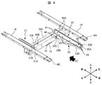
- FIG. 4 is a perspective view showing the underfloor side beam fixed to the lower beam and the suspension mounting bracket
- FIG. 5 is an arrow view of FIG. 4 as viewed from the R1 direction
- FIG. 6 is a suspension portion of FIG. 5 as viewed from the L direction
- FIG. 7 is an arrow view of the mounting bracket and the reinforcing bracket
- FIG. 7 is an arrow view of FIG. 6 as viewed from the R2 direction
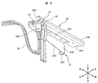
- FIG. 8 is a perspective view showing a state in which the tail cord is hung on the suspended portion of the suspended portion mounting bracket.
- the suspension portion mounting brackets 20 and 21 are fixed to the mounting portions 10A and 10B on the lower beam 10.
- the suspension portion mounting brackets 20 and 21 are provided with flat surface portions 20A and 21A and curved portions 20B and 21B, respectively.
- the curved portions 20B and 21B are formed at the end portions of the flat surface portions 20A and 21A in the lateral direction (left-right direction) orthogonal to the longitudinal direction (front-back direction), and are U-shaped upward from the flat surface portions 20A and 21A. It is bent and formed.
- the curved portions 20B and 21B are formed along the longitudinal direction of the suspension portion mounting brackets 20 and 21.
- the suspension portion mounting brackets 20 and 21 are arranged so that their longitudinal directions are orthogonal to the longitudinal direction of the lower beam 10 and are fixed to the mounting portions 10A and 10B of the lower beam 10.
- the suspended portion mounting brackets 20 and 21 are in the state of a cantilever, but in this embodiment, since the curved portions 20B and 21B are formed along the longitudinal direction, the shear stress applied to the suspended portion mounting brackets 20 and 21 is applied. It is possible to secure the strength against the above.
- the reinforcing bracket 23 is provided below the suspension mounting bracket 20.
- the reinforcing bracket 23 is provided so that its longitudinal direction is along the longitudinal direction of the suspension mounting bracket 20.
- a reinforcing bracket is also provided below the suspension mounting bracket 21.
- the configuration of the reinforcing bracket 23 mounted below the suspension mounting bracket 20 will be described, but the same applies to the reinforcing bracket mounted to the suspension mounting bracket 21.
- the reinforcing bracket 23 is formed in an L shape when viewed from the longitudinal direction (front-back direction), has an upper surface portion 23A in the horizontal direction, and has a vertical direction orthogonal to the upper surface portion 23A. A vertical portion 23B extending downward from the upper surface portion 23A is provided (in the vertical direction).
- the reinforcing bracket 23 is formed to have a length in the longitudinal direction shorter than that of the suspension mounting bracket 20.
- the upper surface portion 23A of the reinforcing bracket 23 and the flat surface portion 20A of the suspension portion mounting bracket 20 face each other and are fixed by a plurality of bolts 43.
- a support portion 23C bent from the vertical portion 23B toward the longitudinal direction (left-right direction) of the lower beam 10 is formed.
- the support portion 23C faces the side surface of the lower beam 10 and is fixed to the lower beam 10 by bolts 44. In this way, the reinforcing bracket 23 is fixed to the lower beam 10 and the suspension mounting bracket 20.
- a part of the load received by the suspension portion mounting bracket 20 is transmitted from the vertical portion 23B to the support portion 23C.
- the load transmitted to the support portion 23C is transmitted to the lower beam 10.
- the load received by the suspension mounting bracket 20 is distributed between the end of the suspension mounting bracket 20 and the support portion 23C of the reinforcing bracket 23, so that the strength of the suspension mounting bracket 20 is increased. Can be secured.
- an inclined portion 23D is formed below the vertical portion 23B of the reinforcing bracket 23, so that the length of the vertical portion 23B in the vertical direction becomes shorter (lower in height) as the distance from the lower beam 10 increases.
- a suspension portion 24 for suspending suspension equipment such as a tail cord is provided below the suspension portion mounting bracket 20, a suspension portion 24 for suspending suspension equipment such as a tail cord is provided.
- the suspension portion 24 is provided with a U-shaped suspension frame body 24A that opens downward and a rod 24B that connects the ends of the open portions of the suspension frame body 24A.
- a U-shaped bottom portion located above is fixed to the suspension portion mounting bracket 20 by bolts 45.
- the rod 24B is formed in a cylindrical shape.
- a suspension device is suspended from the suspension portion 24.
- the tail cord 30 is suspended from the suspension portion 24.
- the tail code 30 passes between the U-shaped bottom of the suspension frame body 24A and the rod 24B, and is suspended from the rod 24B.
- the suspension portion mounting bracket 20 is fixed to the lower beam 10, and the suspension portion 24 for suspending the suspension device is fixed to the suspension portion mounting bracket 20. Since the suspension portion mounting bracket 20 is fixed to the mounting portions 10A and 10B of the lower beam 10 with bolts 41, the position of the suspension portion mounting bracket 20 can be freely changed by simply changing the fastening position with the bolt 41. can do. As shown in FIG. 4, a plurality of bolts 41 for fixing the suspension mounting bracket 20 along the longitudinal direction of the lower beam 10 are inserted into the mounting portions 10A and 10B of the lower beam 10 of the present embodiment. Mounting holes 60A and 60B are formed. Further, on the side surface of the lower beam 10, a plurality of support portion mounting holes 61A and 61B for fixing the reinforcing bracket 23 are formed corresponding to the plurality of mounting holes 60A and 60B.
- any mounting hole from the plurality of mounting holes 60A and 60B according to the specifications of the elevator insert the bolt 41, and attach the suspension mounting bracket 20. Fix it.
- the position for mounting the suspension device can be freely changed.
- the length and the stretching direction of the suspension portion mounting bracket 20 are appropriately selected according to the specifications of the elevator and the type of suspension equipment. For example, in FIG. 4, the suspension portion mounting bracket 21 shorter than the length of the suspension portion mounting bracket 20 is fixed to the lower beam 10. The extension direction of the suspension mounting bracket 21 is different from that of the suspension mounting bracket 20.
- the suspension mounting bracket for mounting the suspension device since the suspension mounting bracket for mounting the suspension device is fixed to the lower beam with bolts, the mounting position, length, etc. of the suspension mounting bracket should be changed according to the specifications of the elevator. This makes it possible to suppress an increase in the number of parts due to changes in elevator specifications.
- the suspension device is suspended when the suspension device is suspended from the suspension mounting bracket.
- the strength of the part mounting bracket can be ensured.
- the present invention is not limited to the above-described embodiment, and includes various modifications.
- the above-mentioned examples have been described in detail in order to explain the present invention in an easy-to-understand manner, and are not necessarily limited to those having all the described configurations.
Landscapes
- Engineering & Computer Science (AREA)
- Civil Engineering (AREA)
- Mechanical Engineering (AREA)
- Structural Engineering (AREA)
- Lift-Guide Devices, And Elevator Ropes And Cables (AREA)
- Cage And Drive Apparatuses For Elevators (AREA)
Priority Applications (3)
| Application Number | Priority Date | Filing Date | Title |
|---|---|---|---|
| PCT/JP2020/020725 WO2021240641A1 (ja) | 2020-05-26 | 2020-05-26 | エレベーターの乗りかご |
| JP2022527314A JP7362922B2 (ja) | 2020-05-26 | 2020-05-26 | エレベーターの乗りかご |
| CN202080101005.7A CN115667115A (zh) | 2020-05-26 | 2020-05-26 | 电梯的轿厢 |
Applications Claiming Priority (1)
| Application Number | Priority Date | Filing Date | Title |
|---|---|---|---|
| PCT/JP2020/020725 WO2021240641A1 (ja) | 2020-05-26 | 2020-05-26 | エレベーターの乗りかご |
Publications (1)
| Publication Number | Publication Date |
|---|---|
| WO2021240641A1 true WO2021240641A1 (ja) | 2021-12-02 |
Family
ID=78723043
Family Applications (1)
| Application Number | Title | Priority Date | Filing Date |
|---|---|---|---|
| PCT/JP2020/020725 Ceased WO2021240641A1 (ja) | 2020-05-26 | 2020-05-26 | エレベーターの乗りかご |
Country Status (3)
| Country | Link |
|---|---|
| JP (1) | JP7362922B2 (https=) |
| CN (1) | CN115667115A (https=) |
| WO (1) | WO2021240641A1 (https=) |
Citations (5)
| Publication number | Priority date | Publication date | Assignee | Title |
|---|---|---|---|---|
| JPS5091263U (https=) * | 1973-12-24 | 1975-08-01 | ||
| JPS52130853U (https=) * | 1976-04-01 | 1977-10-05 | ||
| JPS5563359U (https=) * | 1978-10-20 | 1980-04-30 | ||
| JP2008290828A (ja) * | 2007-05-23 | 2008-12-04 | Hitachi Ltd | エレベーター装置 |
| JP2016196337A (ja) * | 2015-04-02 | 2016-11-24 | 株式会社日立製作所 | エレベーター装置 |
Family Cites Families (3)
| Publication number | Priority date | Publication date | Assignee | Title |
|---|---|---|---|---|
| CN108316552B (zh) * | 2018-04-23 | 2024-06-11 | 精工工业建筑系统有限公司 | 一种超长z型檩条防变形结构 |
| CN208950358U (zh) * | 2018-08-29 | 2019-06-07 | 国网江苏省电力有限公司扬州供电分公司 | 一种既有c型钢檩条的增高加固结构 |
| CN210421416U (zh) * | 2019-07-10 | 2020-04-28 | 河南天丰钢结构建设有限公司 | 钢结构建筑用加强型l型钢及钢结构集束组合构件 |
-
2020
- 2020-05-26 WO PCT/JP2020/020725 patent/WO2021240641A1/ja not_active Ceased
- 2020-05-26 JP JP2022527314A patent/JP7362922B2/ja active Active
- 2020-05-26 CN CN202080101005.7A patent/CN115667115A/zh active Pending
Patent Citations (5)
| Publication number | Priority date | Publication date | Assignee | Title |
|---|---|---|---|---|
| JPS5091263U (https=) * | 1973-12-24 | 1975-08-01 | ||
| JPS52130853U (https=) * | 1976-04-01 | 1977-10-05 | ||
| JPS5563359U (https=) * | 1978-10-20 | 1980-04-30 | ||
| JP2008290828A (ja) * | 2007-05-23 | 2008-12-04 | Hitachi Ltd | エレベーター装置 |
| JP2016196337A (ja) * | 2015-04-02 | 2016-11-24 | 株式会社日立製作所 | エレベーター装置 |
Also Published As
| Publication number | Publication date |
|---|---|
| JP7362922B2 (ja) | 2023-10-17 |
| JPWO2021240641A1 (https=) | 2021-12-02 |
| CN115667115A (zh) | 2023-01-31 |
Similar Documents
| Publication | Publication Date | Title |
|---|---|---|
| JP4350988B2 (ja) | マシンルームレスエレベータ | |
| WO2020213147A1 (ja) | エレベーター乗りかご、及びこの乗りかごを備えたエレベーター | |
| CN107250023A (zh) | 电梯 | |
| US20020040831A1 (en) | Elevator with drive unit supported by guide rail | |
| JP5065766B2 (ja) | エレベーター装置 | |
| JP4726295B2 (ja) | エレベータ | |
| KR101690856B1 (ko) | 엘리베이터 장치 | |
| JP5001013B2 (ja) | エレベータ装置 | |
| JP6432926B1 (ja) | エレベータ装置 | |
| WO2021240641A1 (ja) | エレベーターの乗りかご | |
| JP4762210B2 (ja) | エレベータ | |
| JP2006264862A (ja) | マシンルームレスエレベータ | |
| JP7531722B2 (ja) | 乗りかごおよびエレベーター | |
| JP6714905B2 (ja) | エレベータ | |
| JP6095020B2 (ja) | エレベータ装置 | |
| WO2010038289A1 (ja) | エレベータ装置 | |
| KR20180086214A (ko) | 엘리베이터 시스템용 기계 장착 구조체 | |
| JP4825475B2 (ja) | エレベータのかご上シーブカバー支持構造 | |
| JP6404493B1 (ja) | エレベータ装置の釣合いおもり及びエレベータ装置 | |
| KR102414241B1 (ko) | 엘리베이터 케이지의 진동저감장치 | |
| JP7587046B2 (ja) | 乗りかご及びエレベーター | |
| JP4290543B2 (ja) | エレベーターの巻上機支持装置 | |
| KR19990073749A (ko) | 엘리베이터의 로우프 제진장치 | |
| HK1107327B (en) | Machineroom-less elevator system and machine support assembly for machineroom-less elevator system | |
| HK1107327A1 (zh) | 无机房电梯系统和用於无机房电梯系统的机械支撑组件 |
Legal Events
| Date | Code | Title | Description |
|---|---|---|---|
| 121 | Ep: the epo has been informed by wipo that ep was designated in this application |
Ref document number: 20938042 Country of ref document: EP Kind code of ref document: A1 |
|
| ENP | Entry into the national phase |
Ref document number: 2022527314 Country of ref document: JP Kind code of ref document: A |
|
| WWE | Wipo information: entry into national phase |
Ref document number: 202217068000 Country of ref document: IN |
|
| NENP | Non-entry into the national phase |
Ref country code: DE |
|
| 122 | Ep: pct application non-entry in european phase |
Ref document number: 20938042 Country of ref document: EP Kind code of ref document: A1 |