WO2021234953A1 - 熱交換器、熱交換器を備えた室外機、および、室外機を備えた空気調和装置 - Google Patents
熱交換器、熱交換器を備えた室外機、および、室外機を備えた空気調和装置 Download PDFInfo
- Publication number
- WO2021234953A1 WO2021234953A1 PCT/JP2020/020346 JP2020020346W WO2021234953A1 WO 2021234953 A1 WO2021234953 A1 WO 2021234953A1 JP 2020020346 W JP2020020346 W JP 2020020346W WO 2021234953 A1 WO2021234953 A1 WO 2021234953A1
- Authority
- WO
- WIPO (PCT)
- Prior art keywords
- heat exchanger
- header
- gas pipe
- refrigerant
- outdoor unit
- Prior art date
- Legal status (The legal status is an assumption and is not a legal conclusion. Google has not performed a legal analysis and makes no representation as to the accuracy of the status listed.)
- Ceased
Links
Images





Classifications
-
- F—MECHANICAL ENGINEERING; LIGHTING; HEATING; WEAPONS; BLASTING
- F25—REFRIGERATION OR COOLING; COMBINED HEATING AND REFRIGERATION SYSTEMS; HEAT PUMP SYSTEMS; MANUFACTURE OR STORAGE OF ICE; LIQUEFACTION SOLIDIFICATION OF GASES
- F25B—REFRIGERATION MACHINES, PLANTS OR SYSTEMS; COMBINED HEATING AND REFRIGERATION SYSTEMS; HEAT PUMP SYSTEMS
- F25B39/00—Evaporators; Condensers
-
- F—MECHANICAL ENGINEERING; LIGHTING; HEATING; WEAPONS; BLASTING
- F28—HEAT EXCHANGE IN GENERAL
- F28F—DETAILS OF HEAT-EXCHANGE AND HEAT-TRANSFER APPARATUS, OF GENERAL APPLICATION
- F28F9/00—Casings; Header boxes; Auxiliary supports for elements; Auxiliary members within casings
- F28F9/02—Header boxes; End plates
Definitions
- the present disclosure relates to a heat exchanger having a plurality of flat tubes, an outdoor unit equipped with a heat exchanger, and an air conditioner equipped with an outdoor unit.
- the heat exchange cores are arranged in two rows in the front and rear in the direction of the wind flow, and the upper header tank and the separate lower header tanks that are common to each other of the heat exchange cores are provided.
- a heat exchanger in which a sufficient temperature difference is secured to improve the heat transfer performance (see, for example, Patent Document 1).
- Patent Document 1 When a conventional heat exchanger as in Patent Document 1 is used for an outdoor unit of an air conditioner capable of operating both cooling operation and heating operation, in the heating operation where the outside air temperature is low, a low temperature and low pressure two-phase refrigerant is used. Flows through the heat exchange core on the wind side, causing a lot of frost there. In the defrosting operation, high-temperature and high-pressure gas refrigerant flows in from the lower header tank on the leeward side and flows to the heat exchange core on the leeward side to defrost. After defrosting, the defrosted water generated on the surface of the heat exchange core flows downward, but tends to collect especially near the lower header tank on the windward side.
- the present disclosure has been made to solve the above problems, and includes a heat exchanger capable of suppressing refreezing of defrosted water, an outdoor unit equipped with a heat exchanger, and an outdoor unit. It is intended to provide an air conditioner.
- the heat exchanger according to the present disclosure is a heat exchanger mounted on an outdoor unit provided with at least one heat exchanger having a plurality of flat tubes along the direction of air flow, and is the most wind-upper side.
- the first header provided at the lower end of the heat exchanger, the second header provided at the upper end or the lower end of the most leeward heat exchanger, and the first header are connected to function as an evaporator.
- At least a part of the gas pipe is provided along the long axis direction of the first header, and at least a part of the gas pipe is in contact with the first header. It is a thing.
- the heat exchanger according to the present disclosure has a plurality of flat tubes, and is composed of a main heat exchanger and an auxiliary heat exchanger in which the number of the flat tubes is smaller than that of the main heat exchanger.
- a heat exchanger mounted on an outdoor unit which is provided with at least one heat exchanger along the air flow direction, and has the first header provided at the lower end of the auxiliary heat exchanger on the windy side, and the most.
- the refrigerant flows in when functioning as an evaporator, and flows out when functioning as a condenser.
- the outdoor unit of the air conditioner according to the present disclosure is equipped with the above heat exchanger.
- the air conditioner according to the present disclosure is equipped with the above-mentioned outdoor unit.
- the outdoor unit provided with the heat exchanger, and the air conditioner provided with the outdoor unit according to the present disclosure at least a part of the gas pipe is provided along the long axis direction of the first header. At least part of the gas pipe is in contact with the first header. Therefore, the heat of the gas pipe through which the high-temperature and high-pressure gas refrigerant flows during the defrosting operation can be transferred to the first header. Then, the heat transferred to the first header is transferred to the defrost water in the vicinity of the first header, and the temperature of the defrost water becomes high. Therefore, even if the heating operation is restarted after the defrosting operation is completed, it is possible to prevent the defrosting water in the vicinity of the first header from refreezing.
- FIG. 1 It is a refrigerant circuit diagram of the air conditioner provided with the heat exchanger which concerns on Embodiment 1.
- FIG. It is the first perspective view of the heat exchanger which concerns on Embodiment 1.
- FIG. It is a second perspective view of the heat exchanger which concerns on Embodiment 1.
- FIG. It is a perspective view which shows the modification of the heat exchanger which concerns on Embodiment 1.
- FIG. 3 is a perspective view of a top-flow type outdoor unit equipped with a heat exchanger and a heat exchanger according to the second embodiment. It is a perspective view of the heat exchanger which concerns on Embodiment 2.
- FIG. It is a top view which shows typically the flow of the refrigerant at the time of the heating operation of the heat exchanger which concerns on Embodiment 2.
- FIG. It is a perspective view which shows typically the flow of the refrigerant at the time of the heating operation of the heat exchanger which concerns on Embodiment 2.
- FIG. It is a top view which shows typically the flow of the refrigerant at the time of the defrosting operation of the heat exchanger which concerns on Embodiment 2.
- FIG. It is a perspective view which shows typically the flow of the refrigerant at the time of the defrosting operation of the heat exchanger which concerns on Embodiment 2.
- FIG. It is a top view which shows typically the flow of the refrigerant at the time of defrosting operation of the modification of the heat exchanger which concerns on Embodiment 2.
- FIG. It is a perspective view which shows typically the flow of the refrigerant at the time of defrosting operation of the modification of the heat exchanger which concerns on Embodiment 2.
- FIG. It is an enlarged front view schematically showing the main part of the heat exchanger according to the third embodiment. It is an enlarged front view schematically showing the main part of the heat exchanger according to the fourth embodiment. It is a perspective view which shows typically the joint of the heat exchanger which concerns on Embodiment 5. It is sectional drawing which shows typically the joint of the heat exchanger which concerns on Embodiment 5.
- FIG. 1 is a refrigerant circuit diagram of an air conditioner 100 provided with a heat exchanger 30 according to the first embodiment.
- the solid line arrow in FIG. 1 indicates the flow of the refrigerant during the cooling operation, and the broken line arrow in FIG. 1 indicates the flow of the refrigerant during the heating operation.
- the heat exchanger 30 is mounted on the outdoor unit 10 of the air conditioner 100 including the outdoor unit 10 and the indoor unit 20.
- the outdoor unit 10 includes a compressor 11, a flow path switching device 12, and a fan 13 in addition to the heat exchanger 30.
- the indoor unit 20 includes a throttle device 21, an indoor heat exchanger 22, and an indoor fan 23.
- the air conditioner 100 includes a refrigerant circuit in which a compressor 11, a flow path switching device 12, a heat exchanger 30, a throttle device 21, and an indoor heat exchanger 22 are connected by a refrigerant pipe and a refrigerant circulates.
- the air conditioner 100 can operate both the cooling operation and the heating operation by switching the flow path switching device 12.
- the compressor 11 sucks in the low temperature and low pressure refrigerant, compresses the sucked refrigerant, and discharges the high temperature and high pressure refrigerant.
- the compressor 11 is composed of, for example, an inverter compressor whose capacity, which is a transmission amount per unit time, is controlled by changing the operating frequency.
- the flow path switching device 12 is, for example, a four-way valve, and switches between cooling operation and heating operation by switching the flow direction of the refrigerant.
- the flow path switching device 12 switches to the state shown by the solid line in FIG. 1 during the cooling operation, and the discharge side of the compressor 11 and the heat exchanger 30 are connected to each other. Further, the flow path switching device 12 switches to the state shown by the broken line in FIG. 1 during the heating operation, and the discharge side of the compressor 11 and the indoor heat exchanger 22 are connected to each other.
- the heat exchanger 30 exchanges heat between the outdoor air and the refrigerant.
- the heat exchanger 30 functions as a condenser that dissipates the heat of the refrigerant to the outdoor air and condenses the refrigerant during the cooling operation. Further, the heat exchanger 30 functions as an evaporator that evaporates the refrigerant during the heating operation and cools the outdoor air by the heat of vaporization at that time.
- the fan 13 supplies outdoor air to the heat exchanger 30, and the amount of air blown to the heat exchanger 30 is adjusted by controlling the rotation speed.
- the throttle device 21 is, for example, an electronic expansion valve capable of adjusting the opening degree of the throttle, and controls the pressure of the refrigerant flowing into the heat exchanger 30 or the indoor heat exchanger 22 by adjusting the opening degree.
- the diaphragm device 21 is provided in the indoor unit 20, but it may be provided in the outdoor unit 10, and the installation location is not limited.
- the indoor heat exchanger 22 exchanges heat between the indoor air and the refrigerant.
- the indoor heat exchanger 22 functions as an evaporator that evaporates the refrigerant during the cooling operation and cools the outdoor air by the heat of vaporization at that time. Further, the indoor heat exchanger 22 functions as a condenser that dissipates the heat of the refrigerant to the outdoor air and condenses the refrigerant during the heating operation.
- the indoor fan 23 supplies indoor air to the indoor heat exchanger 22, and the amount of air blown to the indoor heat exchanger 22 is adjusted by controlling the rotation speed.
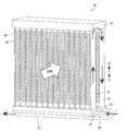
- FIG. 2 is a first perspective view of the heat exchanger 30 according to the first embodiment.
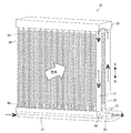
- FIG. 3 is a second perspective view of the heat exchanger 30 according to the first embodiment.
- the white arrows in FIGS. 2 and 3 indicate the flow of wind generated by the fan 13.
- the black dashed arrows in FIGS. 2 and 3 indicate the flow of the refrigerant.
- the heat exchanger 30 has a plurality of heat exchangers along the air flow direction. Specifically, the heat exchanger 30 has a first heat exchanger 31 on the windward side and a second heat exchanger 32 on the leeward side.
- the heat exchanger has a plurality of flat tubes 38 and a plurality of fins 39.
- the flat pipes 38 are arranged in parallel in the horizontal direction at intervals so that the wind generated by the fan 13 flows, and the refrigerant flows in the vertical direction in the pipes extending in the vertical direction.
- the fins 39 are connected between adjacent flat tubes 38 and transfer heat to the flat tubes 38.
- the fin 39 improves the heat exchange efficiency between the air and the refrigerant, and for example, a corrugated fin is used. However, it is not limited to this. Since heat exchange between air and the refrigerant is performed on the surface of the flat tube 38, the fins 39 may not be present.
- a first header 34 is provided at the lower end of the first heat exchanger 31.
- the lower end of the flat tube 38 of the first heat exchanger 31 is directly inserted into the first header 34.
- the first header 34 is connected to the refrigerant circuit of the air conditioner 100 via the liquid pipe 36.
- the first header 34 is also called a liquid header.
- An opening (not shown) is formed in a portion of the first header 34 to which the liquid pipe 36 is connected.
- the first header 34 causes a low-temperature low-pressure two-phase refrigerant to flow into the heat exchanger 30 during the heating operation, and is heat-exchanged by the heat exchanger 30 during the cooling operation as shown in FIG.
- the low temperature and high pressure liquid refrigerant is discharged to the refrigerant circuit.
- a second header 35 is provided at the lower end of the second heat exchanger 32.
- the lower end of the flat tube 38 of the second heat exchanger 32 is directly inserted into the second header 35.
- the second header 35 is arranged in parallel with the first header 34.
- the second header 35 is connected to the refrigerant circuit of the air conditioner 100 via the gas pipe 37.
- the second header 35 is also called a gas header.
- An opening (not shown) is formed in a portion of the second header 35 to which the gas pipe 37 is connected.
- the second header 35 causes the high-temperature and high-pressure gas refrigerant from the compressor 11 to flow into the heat exchanger 30 during the cooling operation, and heat exchanges with the heat exchanger 30 during the heating operation as shown in FIG.
- the low-temperature low-pressure gas refrigerant after the heat is discharged to the refrigerant circuit.
- the inlet of the refrigerant becomes the gas pipe 37 connected to the second header 35, and the outlet of the refrigerant becomes the liquid pipe 36 connected to the first header 34. Further, during the heating operation, the inlet of the refrigerant becomes the liquid pipe 36 connected to the first header 34, and the outlet of the refrigerant becomes the gas pipe 37 connected to the second header 35.
- a row header 33 into which the upper ends of the plurality of flat tubes 38 inserted in the first header 34 and the second header 35 are inserted is provided. Has been done.
- the plurality of flat pipes 38, fins 39, first header 34, second header 35, row passing header 33, liquid pipe 36, and gas pipe 37 are all made of aluminum and are joined by brazing.
- the high-temperature and high-pressure gas refrigerant discharged from the compressor 11 flows into the heat exchanger 30 via the flow path switching device 12.
- the high-temperature and high-pressure gas refrigerant flowing into the heat exchanger 30 exchanges heat with the outdoor air taken in by the fan 13 and condenses while radiating heat, becomes a low-temperature and high-pressure liquid refrigerant, and flows out from the heat exchanger 30.
- the refrigerant flowing in the heat exchanger 30 is the gas pipe 37, the second header 35, the second heat exchanger 32, the row passing header 33, the first heat exchanger 31, the first.
- the header 34 and the liquid pipe 36 flow in this order.
- the low-temperature, high-pressure liquid refrigerant flowing out of the heat exchanger 30 is depressurized by the drawing device 21, becomes a low-temperature, low-pressure, gas-liquid two-phase refrigerant, and flows into the indoor heat exchanger 22.
- the low-temperature low-pressure gas-liquid two-phase refrigerant flowing into the indoor heat exchanger 22 exchanges heat with the indoor air taken in by the indoor fan 23 and evaporates while absorbing heat, cooling the indoor air and forming a low-temperature low-pressure gas refrigerant. Then, it flows out from the indoor heat exchanger 22.
- the low-temperature low-pressure gas refrigerant flowing out of the indoor heat exchanger 22 is sucked into the compressor 11 and becomes a high-temperature high-pressure gas refrigerant again.
- the high-temperature and high-pressure gas refrigerant discharged from the compressor 11 flows into the indoor heat exchanger 22 via the flow path switching device 12.
- the high-temperature and high-pressure gas refrigerant that has flowed into the indoor heat exchanger 22 exchanges heat with the indoor air taken in by the indoor fan 23 and condenses while radiating heat, heating the indoor air and becoming a low-temperature and high-pressure liquid refrigerant in the room. It flows out from the heat exchanger 22.
- the low-temperature and high-pressure liquid refrigerant flowing out of the indoor heat exchanger 22 is depressurized by the throttle device 21, becomes a low-temperature and low-pressure gas-liquid two-phase refrigerant, and flows into the heat exchanger 30.
- the low-temperature low-pressure gas-liquid two-phase refrigerant that has flowed into the heat exchanger 30 exchanges heat with the outdoor air taken in by the fan 13 and evaporates while absorbing heat, becoming a low-temperature low-pressure gas refrigerant and flowing out of the heat exchanger 30. do.
- the refrigerant flowing in the heat exchanger 30 is the liquid pipe 36, the first header 34, the first heat exchanger 31, the row passing header 33, the second heat exchanger 32, and the second.
- the header 35 and the gas pipe 37 flow in this order.
- the low-temperature low-pressure gas refrigerant flowing out of the heat exchanger 30 is sucked into the compressor 11 and becomes a high-temperature high-pressure gas refrigerant again.
- the fan 13 In the defrosting operation, the fan 13 is stopped, the flow path switching device 12 is switched to the same state as in the cooling operation, and the high temperature and high pressure gas refrigerant flows into the heat exchanger 30. This melts the frost attached to the flat tube 38 and the fins 39.
- the defrosting operation is started, the high-temperature and high-pressure gas refrigerant flows into each flat tube 38 via the second header 35. Then, the frost adhering to the flat tube 38 and the fins 39 is melted and changed to water by the high-temperature refrigerant flowing into the flat tube 38.
- defrost water 50 The water generated by melting the frost (hereinafter referred to as defrost water 50) is drained to the lower part of the heat exchanger 30 along the flat pipe 38 or the fin 39.
- defrost water 50 The water generated by melting the frost (hereinafter referred to as defrost water 50) is drained to the lower part of the heat exchanger 30 along the flat pipe 38 or the fin 39.
- the low-temperature low-pressure two-phase refrigerant flows through the first heat exchanger 31 on the wind side, so that the frost on the heat exchanger 30 is caused by the first heat exchanger 31 on the wind side.
- the number is larger than that of the second heat exchanger 32 on the leeward side. Therefore, the defrosting water 50 generated on the surface of the first heat exchanger 31 after defrosting flows downward and collects in the vicinity of the first header 34 at the lower end of the first heat exchanger 31, especially in the upper part of the first header 34. Cheap.
- the low-temperature low-pressure two-phase refrigerant flows in from the first header 34, so that the defrost water 50 accumulated in the upper part of the first header 34 is re-frozen and becomes root ice in the conventional case. This has led to a decrease in heating capacity and damage to the heat exchanger 30.
- At least a part of the gas pipe 37 is provided along the long axis direction of the first header 34, and at least a part of the gas pipe 37 is the first header 34. Is in contact with. Further, the gas pipe 37 is arranged below the first header 34. In this way, at least a part of the gas pipe 37 is provided along the long axis direction of the first header 34, and at least a part of the gas pipe 37 comes into contact with the first header 34, so that the temperature and pressure are high and high during the defrosting operation. The heat of the gas pipe 37 through which the gas refrigerant of No. 1 flows can be transferred to the first header 34.
- the heat transferred to the first header 34 is transmitted to the defrost water 50 in the vicinity of the first header 34, and the temperature of the defrost water 50 becomes high. Therefore, even if the heating operation is restarted after the defrosting operation is completed, it is possible to prevent the defrosting water 50 in the vicinity of the first header 34 from refreezing. As a result, it is possible to suppress a decrease in heating capacity and damage to the heat exchanger 30. Further, since the gas pipe 37 is arranged below the first header 34 and does not interfere with the drainage path of the defrost water 50, deterioration of the drainage property can be prevented. The wider the contact area between the gas pipe 37 and the first header 34, the more heat of the gas pipe 37 can be transferred to the first header 34.
- the heat exchanger 30 has two heat exchangers, but is not limited thereto, and may have one or three or more heat exchangers.
- FIG. 4 is a perspective view showing a modified example of the heat exchanger 30 according to the first embodiment.
- a first header 34 is provided at the lower end of the heat exchanger 311 and a first header 34 is provided at the upper end of the heat exchanger 311.
- the two headers 35 are provided, and the column passing header 33 is not provided.
- the liquid pipe 36 is connected to the first header 34, and the gas pipe 37 is connected to the second header 35.
- the first header 34 is provided at the lower end of the most leeward heat exchanger, and the first header 34 is provided at the upper end of the leeward heat exchanger.
- Two headers 35 are provided.
- the number of heat exchangers-1 column passing header 33 is provided to connect adjacent heat exchangers to each other. Then, the liquid pipe 36 is connected to the first header 34, and the gas pipe 37 is connected to the second header 35.
- the first header 34 is provided at the lower end of the heat exchanger on the most upwind side, and the first header 34 is provided at the lower end of the heat exchanger on the leeward side.
- Two headers 35 are provided.
- the number of heat exchangers-1 column passing header 33 is provided to connect adjacent heat exchangers to each other. Then, the liquid pipe 36 is connected to the first header 34, and the gas pipe 37 is connected to the second header 35.
- the heat exchanger 30 is a heat exchanger 30 having at least one heat exchanger having a plurality of flat tubes 38 along the air flow direction, and is the most windy side.
- a first header provided at the lower end of the heat exchanger, a second header provided at the upper end or the lower end of the most leeward heat exchanger, and a refrigerant when connected to the first header and functioning as an evaporator.
- It is provided with a gas pipe 37. At least a part of the gas pipe 37 is provided along the long axis direction of the first header, and at least a part of the gas pipe 37 is in contact with the first header.
- the heat exchanger 30 According to the heat exchanger 30 according to the first embodiment, at least a part of the gas pipe 37 is provided along the long axis direction of the first header 34, and at least a part of the gas pipe 37 is provided in the first header. It is in contact with 34. Therefore, the heat of the gas pipe 37 through which the high-temperature and high-pressure gas refrigerant flows during the defrosting operation can be transferred to the first header 34. Then, the heat transferred to the first header 34 is transmitted to the defrost water in the vicinity of the first header 34, and the temperature of the defrost water 50 becomes high.
- the gas pipe 37 is arranged below the first header 34.
- the gas pipe 37 is arranged below the first header 34 and does not interfere with the drainage path of the defrost water 50, so that deterioration of the drainage property is prevented. be able to.
- the outdoor unit 10 according to the first embodiment is provided with the above heat exchanger 30. According to the outdoor unit 10 according to the first embodiment, the same effect as that of the heat exchanger 30 can be obtained.
- the air conditioner 100 according to the first embodiment is provided with the above-mentioned outdoor unit 10. According to the air conditioner 100 according to the first embodiment, the same effect as that of the outdoor unit 10 can be obtained.
- Embodiment 2 Hereinafter, the second embodiment will be described, but the description of the parts overlapping with the first embodiment will be omitted, and the same parts or the corresponding parts as those of the first embodiment will be designated by the same reference numerals.
- FIG. 5 is a perspective view of the top-flow type outdoor unit 10a on which the heat exchanger 30 and the heat exchanger 30 according to the second embodiment are mounted.
- the heat exchanger 30 according to the second embodiment is mounted on the top flow type outdoor unit 10a.
- the heat exchanger 30 has an L-shape in a plan view, and is mounted on the outdoor unit 10a so that the two heat exchangers 30 form a rectangular shape in a plan view.
- the heat exchanger 30 does not have to have a strictly L-shape in a plan view. Further, the two heat exchangers 30 do not have to form a strictly rectangular shape in a plan view.
- the outdoor unit 10a includes a box-shaped casing 15. A suction port 16 is formed on each of the four side surfaces of the casing 15, and an air outlet 17 is formed on the upper surface of the casing 15. Further, the outdoor unit 10a includes two heat exchangers 30 arranged in the casing 15 so as to be along the suction ports 16 on each of the four side surfaces of the casing 15. Further, the outdoor unit 10a is arranged inside the fan guard 18 provided so as to be ventilated so as to cover the air outlet 17 of the casing 15, and the outside air is sucked from the suction port 16 and the outside air is sucked from the air outlet 17. It is equipped with a fan 13 for discharging.
- the two heat exchangers 30 are arranged below the fan 13. Further, the two heat exchangers 30 are arranged along the four side surfaces of the casing 15. The two heat exchangers 30 are fixed to the pillars 15a provided at the four corners of the casing 15 with screws or the like. Then, the outdoor air sucked from the suction ports 16 formed on each side surface by the fan 13 is heat-exchanged with the refrigerant by each heat exchanger 30 and then blown out from the outlet 17.
- side panels 15b are provided on each of the four side surfaces of the casing 15, and a machine room (not shown) in which the compressor 11 and the like are housed is formed in the space surrounded by the side panels 15b. ..
- the side panel 15b is formed below the two heat exchangers 30.
- a gap 19 is formed between each side panel 15b and each heat exchanger 30. This gap 19 serves as a handling space for the gas pipe 37. Further, the gap 19 is a space for securing a drainage path for the defrosted water generated in the heat exchanger 30. That is, the gap 19 makes it possible to provide the gas pipe 37 along the long axis direction of the auxiliary side first header 34b of the heat exchanger 30, and also prevents deterioration of drainage.
- FIG. 6 is a perspective view of the heat exchanger 30 according to the second embodiment.
- the heat exchanger 30 according to the second embodiment has a plurality of heat exchangers along the air flow direction. Specifically, the heat exchanger 30 has a first heat exchanger 31 on the windward side and a second heat exchanger 32 on the leeward side.
- the first heat exchanger 31 is composed of a main side first heat exchanger 31a and an auxiliary side first heat exchanger 31b in which the number of flat tubes 38 is smaller than that of the main side first heat exchanger 31a.
- the second heat exchanger 32 is composed of a main side second heat exchanger 32a and an auxiliary side second heat exchanger 32b in which the number of flat tubes 38 is smaller than that of the main side second heat exchanger 32a.
- the heat exchanger 30 is divided into a main heat exchange unit 30a and an auxiliary heat exchange unit 30b.
- the main heat exchange unit 30a includes a main side first heat exchanger 31a, a main side second heat exchanger 32a, a main side first header 34a (hereinafter, also referred to as a first header), a main side second header 35a, and a main side. It is provided with a column passing header 33a.
- the auxiliary heat exchange unit 30b includes an auxiliary side first heat exchanger 31b (hereinafter, also referred to as a second header), an auxiliary side second heat exchanger 32b, an auxiliary side first header 34b, and an auxiliary side second header 35b. It is provided with an auxiliary side column passing header 33b.
- a main side first header 34a is provided at the lower end of the main side first heat exchanger 31a.
- the lower end of the flat tube 38 of the main side first heat exchanger 31a is directly inserted into the main side first header 34a.
- the main side first header 34a is connected to the refrigerant circuit of the air conditioner 100 via the gas pipe 37.
- An opening 34a1 is formed in a portion of the first header 34a on the main side to which the gas pipe 37 is connected.
- the first header 34a on the main side causes the high-temperature and high-pressure gas refrigerant from the compressor 11 to flow into the heat exchanger 30 during the cooling operation, and the low-temperature and low-pressure gas refrigerant after the heat is exchanged by the heat exchanger 30 during the heating operation. Let it flow out to the refrigerant circuit.
- An auxiliary side first header 34b is provided at the lower end of the auxiliary side first heat exchanger 31b.
- the lower end of the flat tube 38 of the auxiliary side first heat exchanger 31b is directly inserted into the auxiliary side first header 34b.
- the first header 34b on the auxiliary side is connected to the refrigerant circuit of the air conditioner 100 via the liquid pipe 36.
- An opening (not shown) is formed in a portion of the auxiliary side first header 34b to which the liquid pipe 36 is connected.
- the first header 34b on the auxiliary side causes a low-temperature low-pressure two-phase refrigerant to flow into the heat exchanger 30 during the heating operation, and the low-temperature high-pressure liquid refrigerant after heat exchange in the heat exchanger 30 during the cooling operation flows out to the refrigerant circuit.
- the inlet of the refrigerant becomes the gas pipe 37 connected to the first header 34a on the main side, and the outlet of the refrigerant becomes the liquid pipe 36 connected to the first header 34b on the auxiliary side. .. Further, during the heating operation, the inlet of the refrigerant becomes the liquid pipe 36 connected to the first header 34b on the auxiliary side, and the outlet of the refrigerant becomes the gas pipe 37 connected to the first header 34a on the main side.
- a main side second header 35a is provided at the lower end of the main side second heat exchanger 32a.
- the lower end of the flat tube 38 of the main side second heat exchanger 32a is directly inserted into the main side second header 35a.
- an auxiliary side second header 35b (see FIG. 7) is provided at the lower end portion of the auxiliary side second heat exchanger 32b.
- the lower end of the flat tube 38 of the auxiliary side second heat exchanger 32b is directly inserted into the auxiliary side second header 35b.
- the main side second header 35a and the auxiliary side second header 35b communicate with each other.
- the upper ends of a plurality of flat tubes 38 inserted into the main side first header 34a and the main side second header 35a are inserted.
- the main side column passing header 33a is provided.
- the upper ends of a plurality of flat tubes 38 inserted into the auxiliary side first header 34b and the auxiliary side second header 35b Is provided with an auxiliary side column passing header 33b into which the is inserted.
- the liquid pipe 36 is connected to the auxiliary side first header 34b, and the gas pipe 37 is connected to the main side first header 34a. At least a part of the gas pipe 37 is provided along the long axis direction of the auxiliary side first header 34b, and at least a part of the gas pipe 37 is in contact with the auxiliary side first header 34b. Further, the gas pipe 37 is arranged below the first header 34b on the auxiliary side.
- the main heat exchange portion 30a has bent portions 41 and 42 (see FIGS. 7 and 9 described later) in the middle of the flow paths of the main side first header 34a and the main side second header 35a, respectively. As a result, the main heat exchange portion 30a can be arranged so as to straddle two side surfaces of the casing 15 adjacent to each other.
- the main side first header 34a and the auxiliary side first header 34b are configured such that the first header 34 is partitioned by a partition plate (not shown) provided inside the first header 34. Further, the main side row passing header 33a and the auxiliary side row passing header 33b are configured by partitioning the row passing header 33 by a partition plate (not shown) provided inside the main side row passing header 33a and the auxiliary side row passing header 33b. That is, the main side first header 34a and the auxiliary side first header 34b, and the main side row passing header 33a and the auxiliary side row passing header 33b are configured by partitioning the same body by a partition plate (not shown). Has been done.
- main side first header 34a and the auxiliary side first header 34b, and the main side column passing header 33a and the auxiliary side column passing header 33b may be configured as separate bodies. Further, the main side second header 35a and the auxiliary side second header 35b are not separated by a partition plate (not shown), and as described above, the main side second header 35a and the auxiliary side second header 35b are Communicate with each other.
- the flow of the refrigerant in the main side first heat exchanger 31a becomes a countercurrent flow to the flow of the refrigerant in the auxiliary side first heat exchanger 31b, and the main side second heat exchanger 32a
- the flow of the refrigerant is configured to be opposite to the flow of the refrigerant in the auxiliary side second heat exchanger 32b.
- FIG. 7 is a plan view schematically showing the flow of the refrigerant during the heating operation of the heat exchanger 30 according to the second embodiment.
- FIG. 8 is a perspective view schematically showing the flow of the refrigerant during the heating operation of the heat exchanger 30 according to the second embodiment. Note that FIG. 8 shows only one heat exchanger 30 surrounded by the broken line in FIG. 7, but the other heat exchanger 30 has the same structure and the same flow of the refrigerant.
- a low-temperature low-pressure gas-liquid two-phase refrigerant flows into the heat exchanger 30 from the liquid pipe 36.
- the low-temperature and low-pressure gas-liquid two-phase refrigerant flowing into the heat exchanger 30 includes an auxiliary side first header 34b, an auxiliary side first heat exchanger 31b, an auxiliary side row passing header 33b, an auxiliary side second heat exchanger 32b, and an auxiliary side.
- Side second header 35b, main side second header 35a, main side second heat exchanger 32a, main side row passing header 33a, main side first heat exchanger 31a, main side first header 34a flow in this order, and low temperature and low pressure. It becomes the gas refrigerant of. Then, the low-temperature low-pressure gas refrigerant flows out of the heat exchanger 30 from the gas pipe 37.
- FIG. 9 is a plan view schematically showing the flow of the refrigerant during the defrosting operation of the heat exchanger 30 according to the second embodiment.
- FIG. 10 is a perspective view schematically showing the flow of the refrigerant during the defrosting operation of the heat exchanger 30 according to the second embodiment. Note that FIG. 10 shows only one heat exchanger 30 surrounded by the broken line in FIG. 9, but the other heat exchanger 30 has the same structure and the same flow of the refrigerant.
- a high-temperature and high-pressure gas refrigerant flows into the heat exchanger 30 from the gas pipe 37.
- the high-temperature and high-pressure gas refrigerant flowing into the heat exchanger 30 includes a main side first header 34a, a main side first heat exchanger 31a, a main side row passing header 33a, a main side second heat exchanger 32a, and a main side second.
- the header 35a, the auxiliary side second header 35b, the auxiliary side second heat exchanger 32b, the auxiliary side row passing header 33b, the auxiliary side first heat exchanger 31b, and the auxiliary side first header 34b flow in this order, and are low temperature and high pressure gas refrigerants. It becomes. Then, the low-temperature and high-pressure gas refrigerant flows out of the heat exchanger 30 from the liquid pipe 36.
- the gas pipe 37 is connected to the main side first header 34a, and during the defrosting operation, the high temperature and high pressure gas refrigerant flows into the heat exchanger 30 from the windward side first header 34a. do. Therefore, it is possible to efficiently defrost the main side first heat exchanger 31a on the windward side where the amount of frost formation is large, and the defrosting time can be shortened. Further, at least a part of the gas pipe 37 is provided along the long axis direction of the auxiliary side first header 34b, and at least a part of the gas pipe 37 is in contact with the auxiliary side first header 34b. Therefore, the heat of the gas pipe 37 through which the high-temperature and high-pressure gas refrigerant flows during the defrosting operation can be transferred to the auxiliary side first header 34b.
- the heat transferred to the auxiliary side first header 34b is transmitted to the defrost water in the vicinity of the auxiliary side first header 34b, and the temperature of the defrost water becomes high. Therefore, even if the heating operation is restarted after the defrosting operation is completed, the defrosting water in the vicinity of the auxiliary side first header 34b at the lower end of the auxiliary side first heat exchanger 31b where the defrosting water tends to collect after defrosting is generated. It is possible to suppress refreezing. As a result, it is possible to suppress a decrease in heating capacity and damage to the heat exchanger 30. Further, since the gas pipe 37 is arranged below the first header 34b on the auxiliary side and does not interfere with the drainage path of the defrosted water, deterioration of the drainage property can be prevented.
- the heat exchanger 30 is mounted on the top-flow type outdoor unit 10a
- the present invention is not limited to this, and the heat exchanger 30 is another type of outdoor unit such as the side-flow type. It can also be installed in.
- the heat exchanger 30 has two heat exchangers, but is not limited thereto, and may have one or three or more heat exchangers.
- FIG. 11 is a plan view schematically showing the flow of the refrigerant during the defrosting operation of the modified example of the heat exchanger 30 according to the second embodiment.
- FIG. 12 is a perspective view schematically showing the flow of the refrigerant during the defrosting operation of the modified example of the heat exchanger 30 according to the second embodiment. Note that FIG. 12 shows only one heat exchanger 30 surrounded by the broken line in FIG. 11, but the other heat exchanger 30 has the same structure.
- a main side first header 34a is provided at the lower end of the main side heat exchanger 31a1 to provide main side heat.
- a second header 35a on the main side is provided at the upper end of the exchanger 31a1.
- an auxiliary side first header 34b is provided at the lower end portion of the auxiliary side heat exchanger 31b1
- an auxiliary side second header 35b is provided at the upper end portion of the auxiliary side heat exchanger 31b1
- a main side row passing header 33a is provided.
- the auxiliary side column passing header 33b is not provided. Then, the liquid pipe 36 is connected to the auxiliary side first header 34b, and the gas pipe 37 is connected to the main side first header 34a.
- the main side first header 34a is provided at the lower end of the wind-upper main side heat exchanger, and the wind-up side auxiliary side heat exchange is provided.
- An auxiliary side first header 34b is provided at the lower end of the body.
- the main side second header 35a is provided at the upper end portion of the main leeward side heat exchanger, and the auxiliary side second header 35b is provided at the upper end portion of the auxiliary side heat exchanger on the leeward side.
- the number of heat exchangers-1 main side row passing header 33a is provided, and adjacent main side heat exchangers are connected to each other.
- the number of heat exchangers-1 auxiliary side row passing header 33b is provided to connect adjacent auxiliary heat exchangers to each other. Then, the liquid pipe 36 is connected to the auxiliary side first header 34b, and the gas pipe 37 is connected to the main side first header 34a.
- the main side first header 34a is provided at the lower end of the most windy side main side heat exchanger, and the most windy side auxiliary side heat exchange is provided.
- An auxiliary side first header 34b is provided at the lower end of the body.
- the main side second header 35a is provided at the lower end of the most leeward main side heat exchanger, and the auxiliary side second header 35b is provided at the lower end of the most leeward auxiliary heat exchanger.
- the number of heat exchangers-1 main side row passing header 33a is provided, and adjacent main side heat exchangers are connected to each other.
- the number of heat exchangers-1 auxiliary side row passing header 33b is provided to connect adjacent auxiliary heat exchangers to each other. Then, the liquid pipe 36 is connected to the auxiliary side first header 34b, and the gas pipe 37 is connected to the main side first header 34a.
- the heat exchanger 30 is composed of a main heat exchanger and an auxiliary heat exchanger in which the number of flat tubes 38 is smaller than that of the main heat exchanger, which has a plurality of flat tubes 38.
- a heat exchanger 30 having at least one heat exchanger provided along the direction of air flow, the first header provided at the lower end of the auxiliary heat exchanger on the most wind side, and the windmost side.
- a liquid pipe connected to the first header and the second header provided at the lower end of the main heat exchanger, in which the refrigerant flows in when functioning as an evaporator and the refrigerant flows out when functioning as a condenser.
- the refrigerant flows out when functioning as an evaporator and the refrigerant flows in when functioning as a condenser.
- At least a part of the gas pipe 37 is provided along the long axis direction of the first header, and at least a part of the gas pipe 37 is in contact with the first header.
- the heat exchanger 30 According to the heat exchanger 30 according to the second embodiment, at least a part of the gas pipe 37 is provided along the long axis direction of the first header 34, and at least a part of the gas pipe 37 is provided in the first header. It is in contact with 34. Therefore, the heat of the gas pipe 37 through which the high-temperature and high-pressure gas refrigerant flows during the defrosting operation can be transferred to the first header 34. Then, the heat transferred to the first header 34 is transmitted to the defrost water in the vicinity of the first header 34, and the temperature of the defrost water 50 becomes high.
- the gas pipe 37 is arranged below the first header 34.
- the gas pipe 37 is arranged below the first header 34 and does not interfere with the drainage path of the defrost water 50, so that deterioration of the drainage property is prevented. be able to.
- the outdoor unit 10 according to the second embodiment includes the above heat exchanger 30. According to the outdoor unit 10 according to the second embodiment, the same effect as that of the heat exchanger 30 can be obtained.
- the outdoor unit 10 of the air conditioner 100 includes the heat exchanger 30, a casing 15 having a suction port 16 on the side surface and an outlet 17 on the upper surface, and the heat exchanger 30.
- a fan 13 provided on the upper side is provided, and the casing 15 has a side panel 15b for covering the machine room formed inside thereof under the heat exchanger 30, and the heat exchanger 30 and the side panel 15b are provided with each other. A gap 19 is formed between them.
- a gap 19 is formed between the heat exchanger 30 and the side panel 15b.
- This gap 19 serves as a space for handling the gas pipe 37 and a space for securing a drainage path for the defrosted water generated in the heat exchanger 30. Therefore, the gap 19 makes it possible to provide the gas pipe 37 along the long axis direction of the auxiliary side first header 34b of the heat exchanger 30, and it is possible to prevent deterioration of drainage.
- the air conditioner 100 according to the second embodiment includes the above-mentioned outdoor unit 10. According to the air conditioner 100 according to the second embodiment, the same effect as that of the outdoor unit 10 can be obtained.
- Embodiment 3 Hereinafter, the third embodiment will be described, but the description thereof will be omitted for the parts overlapping with the second embodiment, and the same parts or the corresponding parts as those in the second embodiment will be designated by the same reference numerals.
- FIG. 13 is an enlarged front view schematically showing a main part of the heat exchanger 30 according to the third embodiment.
- the gas pipe 37 is provided along the long axis direction of the auxiliary side first header 34b.
- the gas pipe 37 is in contact with the auxiliary side first header 34b in the entire area 34b1 in which the flat pipe 38 is provided. Further, the gas pipe 37 is arranged below the first header 34b on the auxiliary side.
- the gas pipe 37 is brought into contact with the auxiliary side first header 34b and the entire area 34b1 in which the flat pipe 38 is provided.
- the heat of the gas pipe 37 through which the high-temperature and high-pressure gas refrigerant flows during the defrosting operation is transferred by the auxiliary side first header 34b, as compared with the case where the gas pipe 37 is only partially in contact with the auxiliary side first header 34b. It can be made easier to convey.
- the heat exchanger 30 when molding the heat exchanger 30, it is possible to braze the gas pipe 37 to the auxiliary side first header 34b at the same time as brazing the flat pipe 38 and fins 39 of the heat exchanger 30 and each header. Therefore, the production of the heat exchanger 30 can be simplified. Further, since the gas pipe 37 is arranged closer to the auxiliary side first header 34b, a space is formed in the lower part of the heat exchanger 30, and a service space can be secured.
- the gas pipe 37 is in contact with the first header in the entire area 34b1 in which the flat pipe 38 is provided.
- the heat of the gas pipe 37 through which the high-temperature and high-pressure gas refrigerant flows during the defrosting operation is compared with the case where the gas pipe 37 is only partially in contact with the first header. Can be easily conveyed by the first header.
- the outdoor unit 10 according to the third embodiment includes the above heat exchanger 30. According to the outdoor unit 10 according to the third embodiment, the same effect as that of the heat exchanger 30 can be obtained.
- the air conditioner 100 according to the third embodiment includes the above-mentioned outdoor unit 10. According to the air conditioner 100 according to the third embodiment, the same effect as that of the outdoor unit 10 can be obtained.
- Embodiment 4 Hereinafter, the fourth embodiment will be described, but the description of the parts overlapping with the second embodiment will be omitted, and the same parts or the corresponding parts as those of the second embodiment will be designated by the same reference numerals.
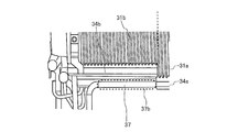
- FIG. 14 is an enlarged front view schematically showing a main part of the heat exchanger 30 according to the fourth embodiment.
- the auxiliary side first header 34b and the main side first header 34a are displaced in the height direction, and the auxiliary side first header 34b is It is arranged above the first header 34a on the main side.
- at least a part of the gas pipe 37 is provided along the long axis direction of the auxiliary side first header 34b.
- at least a part of the gas pipe 37 is in contact with the auxiliary side first header 34b.
- the gas pipe 37 is arranged below the first header 34b on the auxiliary side. Therefore, the portion (hereinafter referred to as a parallel portion) 37b parallel to the auxiliary side first header 34b of the gas pipe 37 is arranged at substantially the same height as the main side first header 34a.
- auxiliary side first header 34b By arranging the auxiliary side first header 34b above the main side first header 34a in this way, a space is formed in the lower part of the heat exchanger 30 and a service space can be secured. Further, since the parallel portion 37b of the gas pipe 37 can be arranged at substantially the same height as the main side first header 34a, the gas pipe 37 is not perpendicular to the main side first header 34a but in the parallel direction. It becomes possible to connect, and it is possible to simplify the piping connection.
- the first header and the second header are displaced in the height direction, and the first header is arranged above the second header.
- the heat exchanger 30 by arranging the first header above the second header, a space is formed in the lower part of the heat exchanger 30 and a service space can be secured. .. Further, since the portion parallel to the first header of the gas pipe 37 can be arranged at substantially the same height as the first header, the gas pipe 37 is not perpendicular to the main side first header 34a but in the parallel direction. It becomes possible to connect to, and it is possible to simplify the piping connection.
- the outdoor unit 10 according to the fourth embodiment includes the above heat exchanger 30. According to the outdoor unit 10 according to the third embodiment, the same effect as that of the heat exchanger 30 can be obtained.
- the air conditioner 100 according to the fourth embodiment includes the above-mentioned outdoor unit 10. According to the air conditioner 100 according to the third embodiment, the same effect as that of the outdoor unit 10 can be obtained.
- Embodiment 5 Hereinafter, the fifth embodiment will be described, but the description thereof will be omitted for the parts that overlap with the second embodiment, and the same parts or the corresponding parts as those in the second embodiment will be designated by the same reference numerals.
- FIG. 15 is a perspective view schematically showing the joint 60 of the heat exchanger 30 according to the fifth embodiment.
- FIG. 16 is a cross-sectional view schematically showing the joint 60 of the heat exchanger 30 according to the fifth embodiment.
- the heat exchanger 30 according to the fifth embodiment includes the joint 60 shown in FIGS. 15 and 16.
- the joint 60 is made of aluminum like the gas pipe 37 and the main side first header 34a. Further, a first opening 60a is formed on one side surface of the joint 60, and a second opening 60b is formed on the upper surface of the joint 60.
- the first opening 60a and the second opening 60b are communicated with each other by an L-shaped communication hole 60c formed inside the joint 60.
- the communication hole 60c does not have to be strictly L-shaped.
- the gas pipe 37 can be made into an L shape. That is, the gas pipe 37 has an L-shape having a joint 60 provided at its corner. Therefore, the gas pipe 37 can be connected in the direction perpendicular to the main side first header 34a.
- the gas pipe 37 is connected in the direction perpendicular to the main side first header 34a without using the joint 60, it is necessary to bend the gas pipe 37, and there is also a space for routing the gas pipe 37. You will need it.
- the gas pipe 37 is connected in the direction perpendicular to the main side first header 34a. It is not necessary to bend the 37, and the piping connection can be simplified. Further, since the space for routing the gas pipe 37 is not required, a space is formed in the lower part of the heat exchanger 30, and a service space can be secured.
- the heat exchanger 30 includes a joint 60 having an L-shaped communication hole 60c formed therein, the gas pipe 37 has an L-shape, and the joint 60 is provided at a corner thereof. It is provided.
- the gas pipe 37 since the gas pipe 37 has an L-shape having a joint 60 provided at its corner, the gas pipe 37 is perpendicular to the first header. It is not necessary to bend the gas pipe 37 when connecting in the direction, and the pipe connection can be simplified. Further, since the space for routing the gas pipe 37 is not required, a space is formed in the lower part of the heat exchanger 30, and a service space can be secured.
- the outdoor unit 10 according to the fifth embodiment includes the above heat exchanger 30. According to the outdoor unit 10 according to the third embodiment, the same effect as that of the heat exchanger 30 can be obtained.
- the air conditioner 100 according to the fifth embodiment includes the above-mentioned outdoor unit 10. According to the air conditioner 100 according to the third embodiment, the same effect as that of the outdoor unit 10 can be obtained.
Landscapes
- Engineering & Computer Science (AREA)
- Physics & Mathematics (AREA)
- Mechanical Engineering (AREA)
- Thermal Sciences (AREA)
- General Engineering & Computer Science (AREA)
- Other Air-Conditioning Systems (AREA)
- Heat-Exchange Devices With Radiators And Conduit Assemblies (AREA)
Priority Applications (2)
| Application Number | Priority Date | Filing Date | Title |
|---|---|---|---|
| PCT/JP2020/020346 WO2021234953A1 (ja) | 2020-05-22 | 2020-05-22 | 熱交換器、熱交換器を備えた室外機、および、室外機を備えた空気調和装置 |
| JP2022524841A JP7357785B2 (ja) | 2020-05-22 | 2020-05-22 | 熱交換器、熱交換器を備えた室外機、および、室外機を備えた空気調和装置 |
Applications Claiming Priority (1)
| Application Number | Priority Date | Filing Date | Title |
|---|---|---|---|
| PCT/JP2020/020346 WO2021234953A1 (ja) | 2020-05-22 | 2020-05-22 | 熱交換器、熱交換器を備えた室外機、および、室外機を備えた空気調和装置 |
Publications (1)
| Publication Number | Publication Date |
|---|---|
| WO2021234953A1 true WO2021234953A1 (ja) | 2021-11-25 |
Family
ID=78708390
Family Applications (1)
| Application Number | Title | Priority Date | Filing Date |
|---|---|---|---|
| PCT/JP2020/020346 Ceased WO2021234953A1 (ja) | 2020-05-22 | 2020-05-22 | 熱交換器、熱交換器を備えた室外機、および、室外機を備えた空気調和装置 |
Country Status (2)
| Country | Link |
|---|---|
| JP (1) | JP7357785B2 (https=) |
| WO (1) | WO2021234953A1 (https=) |
Cited By (1)
| Publication number | Priority date | Publication date | Assignee | Title |
|---|---|---|---|---|
| WO2023233572A1 (ja) * | 2022-06-01 | 2023-12-07 | 三菱電機株式会社 | 熱交換器及び冷凍サイクル装置 |
Citations (5)
| Publication number | Priority date | Publication date | Assignee | Title |
|---|---|---|---|---|
| US20130312436A1 (en) * | 2012-05-22 | 2013-11-28 | Nordyne Llc | Heat pump with improved defrost cycle and method of defrosting a heat exchanger |
| CN106918167A (zh) * | 2015-12-24 | 2017-07-04 | 杭州三花微通道换热器有限公司 | 换热装置和具有所述换热装置的制冷剂蒸汽压缩系统 |
| JP2018096638A (ja) * | 2016-12-15 | 2018-06-21 | 日野自動車株式会社 | 凝縮器 |
| US10048024B1 (en) * | 2017-04-26 | 2018-08-14 | Joshua D. Sole | Two-phase fluid flow distributor and method for parallel microchannel evaporators and condensers |
| WO2019239446A1 (ja) * | 2018-06-11 | 2019-12-19 | 三菱電機株式会社 | 空気調和装置の室外機及び空気調和装置 |
Family Cites Families (1)
| Publication number | Priority date | Publication date | Assignee | Title |
|---|---|---|---|---|
| AUPQ730600A0 (en) * | 2000-05-04 | 2000-05-25 | Canon Kabushiki Kaisha | A method for self-programming smart cards |
-
2020
- 2020-05-22 WO PCT/JP2020/020346 patent/WO2021234953A1/ja not_active Ceased
- 2020-05-22 JP JP2022524841A patent/JP7357785B2/ja active Active
Patent Citations (5)
| Publication number | Priority date | Publication date | Assignee | Title |
|---|---|---|---|---|
| US20130312436A1 (en) * | 2012-05-22 | 2013-11-28 | Nordyne Llc | Heat pump with improved defrost cycle and method of defrosting a heat exchanger |
| CN106918167A (zh) * | 2015-12-24 | 2017-07-04 | 杭州三花微通道换热器有限公司 | 换热装置和具有所述换热装置的制冷剂蒸汽压缩系统 |
| JP2018096638A (ja) * | 2016-12-15 | 2018-06-21 | 日野自動車株式会社 | 凝縮器 |
| US10048024B1 (en) * | 2017-04-26 | 2018-08-14 | Joshua D. Sole | Two-phase fluid flow distributor and method for parallel microchannel evaporators and condensers |
| WO2019239446A1 (ja) * | 2018-06-11 | 2019-12-19 | 三菱電機株式会社 | 空気調和装置の室外機及び空気調和装置 |
Cited By (4)
| Publication number | Priority date | Publication date | Assignee | Title |
|---|---|---|---|---|
| WO2023233572A1 (ja) * | 2022-06-01 | 2023-12-07 | 三菱電機株式会社 | 熱交換器及び冷凍サイクル装置 |
| JPWO2023233572A1 (https=) * | 2022-06-01 | 2023-12-07 | ||
| GB2632959A (en) * | 2022-06-01 | 2025-02-26 | Mitsubishi Electric Corp | Heat exchanger, and refrigeration cycle device |
| JP7738754B2 (ja) | 2022-06-01 | 2025-09-12 | 三菱電機株式会社 | 熱交換器及び冷凍サイクル装置 |
Also Published As
| Publication number | Publication date |
|---|---|
| JP7357785B2 (ja) | 2023-10-06 |
| JPWO2021234953A1 (https=) | 2021-11-25 |
Similar Documents
| Publication | Publication Date | Title |
|---|---|---|
| CN112204312B (zh) | 空气调节装置的室外机及空气调节装置 | |
| CN110612425B (zh) | 热交换器 | |
| JP7317231B2 (ja) | 熱交換器、熱交換器を備えた室外機、および、室外機を備えた空気調和装置 | |
| JP6521116B1 (ja) | 熱交換器又は熱交換器を有する冷凍装置 | |
| JP2019128060A (ja) | 室内熱交換器および空気調和装置 | |
| JP2019011923A (ja) | 熱交換器 | |
| JP6925393B2 (ja) | 空気調和装置の室外機及び空気調和装置 | |
| JP6987227B2 (ja) | 熱交換器及び冷凍サイクル装置 | |
| US20200200477A1 (en) | Heat exchanger and heat exchange unit including the same | |
| JP7353483B2 (ja) | 熱交換器及び該熱交換器を備えた空気調和機 | |
| JP7357785B2 (ja) | 熱交換器、熱交換器を備えた室外機、および、室外機を備えた空気調和装置 | |
| EP3825628A1 (en) | Refrigeration cycle device | |
| WO2021095452A1 (ja) | 熱交換器及び空気調和装置 | |
| JP2019184192A (ja) | 室外ユニット | |
| US11994352B2 (en) | Heat exchanger | |
| JP2018138826A (ja) | 空気調和装置 | |
| JP6587003B2 (ja) | 熱交換器 | |
| US20200200476A1 (en) | Heat exchanger | |
| JP7011187B2 (ja) | 冷媒分流器、及び、空気調和機 | |
| JP7080395B2 (ja) | 熱交換器ユニット及び冷凍サイクル装置 | |
| JP7675951B1 (ja) | 熱交換器及び空気調和装置 | |
| JP7724953B2 (ja) | 熱交換器及びこれを有する空気調和装置 | |
| JP7642170B1 (ja) | 熱交換器、熱交換器を備えた室外機、および、室外機を備えた空気調和装置 | |
| JP7258151B2 (ja) | 熱交換器および冷凍サイクル装置 | |
| JP7089187B2 (ja) | 熱交換器及び空気調和装置 |
Legal Events
| Date | Code | Title | Description |
|---|---|---|---|
| 121 | Ep: the epo has been informed by wipo that ep was designated in this application |
Ref document number: 20936747 Country of ref document: EP Kind code of ref document: A1 |
|
| ENP | Entry into the national phase |
Ref document number: 2022524841 Country of ref document: JP Kind code of ref document: A |
|
| NENP | Non-entry into the national phase |
Ref country code: DE |
|
| 122 | Ep: pct application non-entry in european phase |
Ref document number: 20936747 Country of ref document: EP Kind code of ref document: A1 |