WO2021230345A1 - 車両用のドアトリム及び車両用の内装部品 - Google Patents
車両用のドアトリム及び車両用の内装部品 Download PDFInfo
- Publication number
- WO2021230345A1 WO2021230345A1 PCT/JP2021/018364 JP2021018364W WO2021230345A1 WO 2021230345 A1 WO2021230345 A1 WO 2021230345A1 JP 2021018364 W JP2021018364 W JP 2021018364W WO 2021230345 A1 WO2021230345 A1 WO 2021230345A1
- Authority
- WO
- WIPO (PCT)
- Prior art keywords
- vehicle
- stopper
- protrusion
- door
- elastic
- Prior art date
- Legal status (The legal status is an assumption and is not a legal conclusion. Google has not performed a legal analysis and makes no representation as to the accuracy of the status listed.)
- Ceased
Links
Images














Classifications
-
- B—PERFORMING OPERATIONS; TRANSPORTING
- B60—VEHICLES IN GENERAL
- B60J—WINDOWS, WINDSCREENS, NON-FIXED ROOFS, DOORS, OR SIMILAR DEVICES FOR VEHICLES; REMOVABLE EXTERNAL PROTECTIVE COVERINGS SPECIALLY ADAPTED FOR VEHICLES
- B60J5/00—Doors
-
- B—PERFORMING OPERATIONS; TRANSPORTING
- B60—VEHICLES IN GENERAL
- B60J—WINDOWS, WINDSCREENS, NON-FIXED ROOFS, DOORS, OR SIMILAR DEVICES FOR VEHICLES; REMOVABLE EXTERNAL PROTECTIVE COVERINGS SPECIALLY ADAPTED FOR VEHICLES
- B60J5/00—Doors
- B60J5/04—Doors arranged at the vehicle sides
-
- B—PERFORMING OPERATIONS; TRANSPORTING
- B60—VEHICLES IN GENERAL
- B60R—VEHICLES, VEHICLE FITTINGS, OR VEHICLE PARTS, NOT OTHERWISE PROVIDED FOR
- B60R13/00—Elements for body-finishing, identifying, or decorating; Arrangements or adaptations for advertising purposes
- B60R13/02—Internal Trim mouldings ; Internal Ledges; Wall liners for passenger compartments; Roof liners
Definitions
- the present invention relates to a door trim for a vehicle and an interior component for a vehicle.
- a door trim (interior part) is provided on the inner surface of the vehicle door.
- Patent Document 1 discloses a door trim provided with a trim holding means that abuts on the door inner panel.
- the trim holding means includes a seat portion integrally projecting from the back surface of the door trim, and a flexibly deformable spring portion integrally molded at the tip of the seat portion.
- the trim holding means is configured such that when the amount of bending deformation of the spring portion exceeds a predetermined amount, the spring portion abuts on the seat portion (see FIG. 4 of Patent Document 1). If such a configuration is adopted, abnormal noise may be generated when the spring portion abuts on the seat portion.
- one aspect of the present invention is a door trim (1) for a vehicle, wherein the trim main body portion (2) provided inside the vehicle of the door panel (P) and the outside of the vehicle from the trim main body portion.
- a stopper (23) and an elastic protrusion (24) projecting toward the door panel are provided, the stopper faces the door panel at a distance, and the elastic protrusion abuts on the door panel.
- a portion (33) and a second contact portion (34) arranged inside the vehicle from the first contact portion and in contact with the stopper are provided.
- the second contact portion of the elastic protrusion is arranged inside the vehicle from the first contact portion of the elastic protrusion, the portion outside the vehicle from the second contact portion of the elastic protrusion. Can be elastically deformed freely. Further, since the elastic protrusions protrude from the trim main body, the length of the elastic protrusions and the amount of elastic deformation (deflection amount) can be sufficiently secured. Therefore, it is possible to enhance the buffering action of the elastic protrusions and effectively suppress the generation of abnormal noise.
- the stopper may be provided with a contact surface (31) that comes into contact with the second contact portion, and the contact surface may have an arc shape that swells toward the outside of the vehicle. ..
- the contact position between the second contact portion and the contact surface can be smoothly displaced according to the displacement of the contact position between the first contact portion and the door panel. Therefore, it is possible to suppress the generation of abnormal noise due to the second contact portion hitting the contact surface.
- the stopper and the elastic protrusion extend in the extending direction along the trim main body portion, and the width (W1) of the elastic protrusion in the extending direction is the stopper in the extending direction. It may be narrower than the width (W2) of.
- the elastic protrusion can be accommodated within the width of the stopper, the elastic protrusion can be stably supported by the stopper.
- the stopper and the elastic protrusion extend in an extending direction along the trim main body portion, and the vehicle inner end portion (26A) of the stopper and the vehicle inner end portion (24A) of the elastic protrusion. May face each other at intervals in a direction orthogonal to the extension direction.
- the degree of freedom of elastic deformation of the elastic protrusion can be increased as compared with the case where the inner end of the stopper and the inner end of the elastic protrusion are in contact with each other. Therefore, the buffering action of the elastic protrusions can be further enhanced, and the generation of abnormal noise can be suppressed more effectively.
- the mold and the door trim (molded product) can be easily separated by moving the mold from one side in the extension direction to the other side after molding the door trim.
- the stopper includes a pair of main wall portions (26) protruding from the trim main body portion toward the outside of the vehicle, and the vehicle outer end portions (26B) of the pair of main wall portions are connected to each other. It may have been done.
- the elastic protrusion can be stably supported by the stopper having a simple structure.
- each main wall portion may be formed to be thinner than the portion other than the vehicle inner end portion of each main wall portion.
- each of the main wall portions extends in an extending direction along the trim main body portion, and is continuous with the inner surface of the vehicle inner end portion of each main wall portion in the extending direction.
- the recess (30) may be formed.
- each main wall can be thinned by a simple configuration.
- each of the main wall portions extends in an extending direction along the trim main body portion, and the stopper is a connecting wall connecting the ends of the pair of main wall portions in the extending direction.
- a portion (28) may be further provided.
- the rigidity of the stopper can be increased, the elastic protrusion can be stably supported by the stopper.
- the elastic protrusion when the elastic protrusion faces the stopper at a distance and the door trim is attached to the door panel in a state where the door trim is not attached to the door panel, the door panel comes into contact with the first contact.
- the elastic protrusion may be elastically deformed by pressing the portion, and the second contact portion may abut on the stopper.
- the elastic protrusion can be stably brought into contact with the door panel and the stopper while the door trim is attached to the door panel. Therefore, the buffering action of the elastic protrusions can be further enhanced, and the generation of abnormal noise can be suppressed more effectively.
- an aspect of the present invention is an interior component (1) for a vehicle, which is a main body portion (2) provided inside the vehicle interior of the exterior component (P) and a vehicle outer surface from the main body portion.
- a stopper (23) and an elastic protrusion (24) projecting toward the surface thereof are provided, the stopper faces the exterior component at a distance, and the elastic projection abuts on the exterior component.
- a contact portion (33) and a second contact portion (34) arranged inside the vehicle from the first contact portion and in contact with the stopper are provided.
- the second contact portion of the elastic protrusion is arranged inside the vehicle from the first contact portion of the elastic protrusion, the portion outside the vehicle from the second contact portion of the elastic protrusion. Can be elastically deformed freely. Further, since the elastic protrusions protrude from the main body, the length of the elastic protrusions and the amount of elastic deformation (deflection amount) can be sufficiently secured. Therefore, it is possible to enhance the buffering action of the elastic protrusions and effectively suppress the generation of abnormal noise.
- One aspect of the present invention is a door trim (1) for a vehicle, in which a trim main body portion (2) provided inside the vehicle of the door panel (P) and a stopper protruding from the trim main body portion toward the outside of the vehicle ( 23) and an elastic protrusion (24), the stopper faces the door panel at a distance, and the elastic protrusion has a first contact portion (33) that abuts on the door panel and the said.
- a second contact portion (34) which is arranged inside the vehicle from the first contact portion and abuts on the stopper, is provided.
- the second contact portion of the elastic protrusion is arranged inside the vehicle from the first contact portion of the elastic protrusion, the portion outside the vehicle from the second contact portion of the elastic protrusion. Can be elastically deformed freely. Further, since the elastic protrusions protrude from the trim main body, the length of the elastic protrusions and the amount of elastic deformation (deflection amount) can be sufficiently secured. Therefore, it is possible to enhance the buffering action of the elastic protrusions and effectively suppress the generation of abnormal noise.
- the stopper may be provided with a contact surface (31) that comes into contact with the second contact portion, and the contact surface may have an arc shape that swells toward the outside of the vehicle. ..
- the contact position between the second contact portion and the contact surface can be smoothly displaced according to the displacement of the contact position between the first contact portion and the door panel. Therefore, it is possible to suppress the generation of abnormal noise due to the second contact portion hitting the contact surface.
- the stopper and the elastic protrusion extend in the extending direction along the trim main body portion, and the width (W1) of the elastic protrusion in the extending direction is the stopper in the extending direction. It may be narrower than the width (W2) of.
- the elastic protrusion can be accommodated within the width of the stopper, the elastic protrusion can be stably supported by the stopper.
- the stopper and the elastic protrusion extend in an extending direction along the trim main body portion, and the vehicle inner end portion (26A) of the stopper and the vehicle inner end portion (24A) of the elastic protrusion. May face each other at intervals in a direction orthogonal to the extension direction.
- the degree of freedom of elastic deformation of the elastic protrusion can be increased as compared with the case where the inner end of the stopper and the inner end of the elastic protrusion are in contact with each other. Therefore, the buffering action of the elastic protrusions can be further enhanced, and the generation of abnormal noise can be suppressed more effectively.
- the mold and the door trim (molded product) can be easily separated by moving the mold from one side in the extension direction to the other side after molding the door trim.
- the stopper includes a pair of main wall portions (26) protruding from the trim main body portion toward the outside of the vehicle, and the vehicle outer end portions (26B) of the pair of main wall portions are connected to each other. It may have been done.
- the elastic protrusion can be stably supported by the stopper having a simple structure.
- each main wall portion may be formed to be thinner than the portion other than the vehicle inner end portion of each main wall portion.
- each of the main wall portions extends in an extending direction along the trim main body portion, and is continuous with the inner surface of the vehicle inner end portion of each main wall portion in the extending direction.
- the recess (30) may be formed.
- each main wall can be thinned by a simple configuration.
- each of the main wall portions extends in an extending direction along the trim main body portion, and the stopper is a connecting wall connecting the ends of the pair of main wall portions in the extending direction.
- a portion (28) may be further provided.
- the rigidity of the stopper can be increased, the elastic protrusion can be stably supported by the stopper.
- the elastic protrusion when the elastic protrusion faces the stopper at a distance and the door trim is attached to the door panel in a state where the door trim is not attached to the door panel, the door panel comes into contact with the first contact.
- the elastic protrusion may be elastically deformed by pressing the portion, and the second contact portion may abut on the stopper.
- the elastic protrusion can be stably brought into contact with the door panel and the stopper while the door trim is attached to the door panel. Therefore, the buffering action of the elastic protrusions can be further enhanced, and the generation of abnormal noise can be suppressed more effectively.
- an aspect of the present invention is an interior component (1) for a vehicle, which is a main body portion (2) provided inside the vehicle interior of the exterior component (P) and a vehicle outer surface from the main body portion.
- a stopper (23) and an elastic protrusion (24) projecting toward the surface thereof are provided, the stopper faces the exterior component at a distance, and the elastic projection abuts on the exterior component.
- a contact portion (33) and a second contact portion (34) arranged inside the vehicle from the first contact portion and in contact with the stopper are provided.
- the second contact portion of the elastic protrusion is arranged inside the vehicle from the first contact portion of the elastic protrusion, the portion outside the vehicle from the second contact portion of the elastic protrusion. Can be elastically deformed freely. Further, since the elastic protrusions protrude from the main body, the length of the elastic protrusions and the amount of elastic deformation (deflection amount) can be sufficiently secured. Therefore, it is possible to enhance the buffering action of the elastic protrusions and effectively suppress the generation of abnormal noise.
- FIG. 1 Perspective view of the door according to the first embodiment Schematic side view of the door trim according to the first embodiment Section III-III sectional view of FIG.
- Perspective view of the abnormal noise suppressing member according to the first embodiment Side view of the abnormal noise suppressing member according to the first embodiment Sectional drawing which shows the state which the pushing pressure is acting on the door which concerns on 1st Embodiment Sectional drawing which shows the state which the door trim which concerns on 1st Embodiment is not attached to a door panel
- Schematic side view of the door trim according to the second embodiment (A) Side view of the abnormal noise suppressing member according to the second embodiment, (B) Rear view of the abnormal noise suppressing member according to the second embodiment.
- FIG. 1 Schematic diagram illustrating the mounting structure of the abnormal noise suppressing member according to the second embodiment to the trim main body portion.
- Perspective view of the door according to the fifth embodiment Perspective view of the armrest according to the fifth embodiment
- the traveling direction of the vehicle (automobile) provided with the door D and the door trim 1 is “front”
- the backward direction is “rear”
- the vertical direction is “up” and “down”
- the vehicle width direction is “left” and “right”.
- the positional relationship is determined as.
- the inside in the vehicle width direction (left-right direction) is defined as “inside the vehicle”
- the outside in the vehicle width direction (left-right direction) is defined as "outside the vehicle”.
- the door D is arranged along the side surface of the vehicle and is provided so as to be openable and closable. As shown in FIG. 1, the door D includes a door trim 1 (an example of an interior component) and a door panel P (an example of an exterior component).
- the door trim 1 has a trim main body portion 2 (an example of the main body portion) provided inside the vehicle of a metal (for example, iron) door panel P.
- the trim main body portion 2 has a main surface portion 3 facing in the vehicle width direction and an edge portion 4 corresponding to the peripheral edge of the main surface portion 3.
- the edge portion 4 extends from the end portion of the main surface portion 3 toward the outside of the vehicle. Further, the vehicle outer end portion of the edge portion 4 is in contact with the door panel P, and is attached to the door panel P via a fastening member such as a clip.
- the door trim 1 is made of resin.
- the door trim 1 has an armrest 6 having an armrest upper wall 7 that bulges inward from the trim main body 2 and faces up and down, and an armrest side wall 8 that extends downward from the inner end of the armrest upper wall 7. ing.
- the armrest 6 bulges from an intermediate portion in the vertical direction of the main surface portion 3.
- the armrest 6 functions as an armrest for the occupant to place his / her arm.
- the armrest upper wall 7 extends substantially horizontally from the main surface portion 3 to the inside of the vehicle.
- the rear end of the armrest side wall 8 is inclined toward the rear to the outside of the vehicle.
- a switch portion 9 for an occupant to open and close a window is provided on the front portion of the armrest upper wall 7.
- the armrest 6 has a built-in heater 10 composed of a heating wire or the like.
- the door trim 1 has a box shape that opens upward, and has a pull pocket body 13 that defines a pull pocket space 14 that is recessed downward from the armrest upper wall 7.
- the pull pocket body 13 functions as a gripping portion for gripping when the occupant opens and closes the door D.
- the pull pocket body 13 is made of resin.
- a speaker grill 16 is provided at the lower front portion of the trim main body portion 2.
- the speaker grill 16 covers the inside of the vehicle of the speaker 17.
- a protector 18 is arranged on the outside of the vehicle at the lower rear portion of the trim main body 2.
- the protector 18 is made of a synthetic resin material such as polypropylene, and absorbs an impact applied to the door panel P at the time of a side collision of the vehicle.
- a door handle 19 for opening and closing the door D from the inside of the vehicle is installed on the upper part of the trim main body 2. The door handle 19 is not shown in FIG.
- ⁇ Abnormal noise suppression member 21> With reference to FIG. 2, two abnormal noise suppressing members 21 are provided on the upper portion of the back surface 2A (the surface on the outer side of the vehicle) of the trim main body 2 at intervals in the front-rear direction. As will be described later, the two abnormal noise suppressing members 21 have a function of suppressing the generation of abnormal noise due to vibration when the vehicle is running, vibration when the door is opened and closed, and the like. In another embodiment, only one abnormal noise suppressing member 21 may be provided in the trim main body 2, or three or more abnormal noise suppressing members 21 may be provided in the trim main body 2. ..
- each abnormal noise suppressing member 21 will be described with reference to a state in which the door trim 1 is assembled to the door panel P (see FIG. 1).
- each abnormal noise suppressing member 21 is arranged above the speaker grill 16 and the protector 18 and below the door handle 19. That is, each abnormal noise suppressing member 21 is arranged so as to avoid the speaker grill 16, the protector 18, and the door handle 19. It is preferable that each abnormal noise suppressing member 21 is arranged so as to avoid the heater 10 built in the armrest 6.
- One or both abnormal noise suppressing members 21 may be arranged inside the vehicle (rear surface side) of the pull pocket body 13.
- each abnormal noise suppressing member 21 includes a stopper 23 and an elastic protrusion 24 arranged so as to overlap the stopper 23 from the front side.
- the elastic protrusion 24 may be arranged so as to overlap the stopper 23 from the rear side, the upper side, or the lower side.
- the stopper 23 and the elastic protrusion 24 may be arranged in the front-rear direction or in the up-down direction.
- the stopper 23 of each abnormal noise suppressing member 21 protrudes from the back surface 2A of the trim main body 2 toward the outside of the vehicle and faces the door panel P at a distance.
- the stopper 23 is integrally formed with the trim main body 2 by the same material as the trim main body 2.
- the stopper 23 may be formed of a material different from that of the trim main body 2, or may be formed separately from the trim main body 2.
- the stopper 23 has a substantially semi-cylindrical shape and extends in the vertical direction (an example of the extending direction along the trim main body 2).
- the stopper 23 has a pair of main wall portions 26 extending in the vertical direction (front main wall portion 26 and a rear main wall portion 26) and a lower end portion of the pair of main wall portions 26 extending in the front-rear direction (vertical direction). It is provided with a connection wall portion 28 for connecting the end portion). In another embodiment, the stopper 23 may include only a pair of main wall portions 26.
- the pair of main wall portions 26 of the stopper 23 project from the back surface 2A of the trim main body portion 2 toward the outside of the vehicle.
- Each main wall portion 26 is curved so as to bulge toward the outside of the vehicle, and is inclined toward the outside of the vehicle toward the front-rear center line C side of the stopper 23.
- a recess 30 continuous in the vertical direction is formed on the inner surface of the vehicle inner end portion 26A (corresponding to the vehicle inner end portion of the entire stopper 23) of each main wall portion 26. Therefore, the vehicle inner end portion 26A of each main wall portion 26 is formed to be thinner than the portion other than the vehicle inner end portion 26A of each main wall portion 26.
- each main wall portion 26 (corresponding to the vehicle outer end portion of the entire stopper 23) is connected to each other at a position overlapping the front-rear center line C of the stopper 23.
- a contact surface 31 is provided on the outer surface of the main wall portion 26 on the front side.
- the contact surface 31 has an arc shape that swells toward the outside of the vehicle.
- connection wall portion 28 of the stopper 23 protrudes from the back surface 2A of the trim main body portion 2 toward the outside of the vehicle.
- the connecting wall portion 28 closes the lower end portion of the space S (that is, the internal space of the stopper 23) formed between the pair of main wall portions 26.
- the elastic protrusion 24 of each abnormal noise suppressing member 21 is arranged adjacent to the stopper 23.
- the elastic protrusion 24 projects from the back surface 2A of the trim main body 2 toward the outside of the vehicle.
- the elastic protrusion 24 is inclined to the rear side (stopper 23 side) toward the outside of the vehicle.
- the elastic protrusion 24 is integrally formed with the trim main body 2 by the same material as the trim main body 2. In another embodiment, the elastic protrusion 24 may be formed separately from the trim main body portion 2 or may be formed of a material different from the trim main body portion 2.
- the elastic protrusion 24 has a thin plate shape and extends in the vertical direction (an example of the extending direction along the trim main body 2).
- the width W1 of the elastic protrusion 24 in the vertical direction is narrower than the width W2 of the stopper 23 in the vertical direction.
- the elastic protrusion 24 has a spring property and is provided so as to be elastically deformable.
- the vehicle inner end 24A of the elastic protrusion 24 faces the vehicle inner end 26A of the main wall 26 on the front side of the stopper 23 at a distance in the front-rear direction (direction orthogonal to the vertical direction).
- the vehicle inner end portion 24A of the elastic projection 24 is slightly inclined forward toward the upper side. Therefore, the facing distance X between the vehicle inner end portion 26A of the main wall portion 26 on the front side of the stopper 23 and the vehicle inner end portion 24A of the elastic protrusion 24 is from the lower side (one side in the vertical direction) to the upper side (the other side in the vertical direction). ) Is getting wider and wider.
- a first contact portion 33 is provided on the vehicle outer end portion 24B of the elastic protrusion 24.
- the first contact portion 33 is in contact with the vehicle inner surface of the door panel P and is pressed against the vehicle inner surface of the door panel P.
- the elastic projection 24 is elastically deformed.
- the first contact portion 33 does not contact the stopper 23 and is elastically deformable. That is, the first contact portion 33 has a free end.
- the first contact portion 33 is located on the outer side of the vehicle with respect to the outer end of the protector 18.
- the elastic projection 24 is provided with a second contact portion 34 inside the vehicle rather than the first contact portion 33.
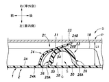
- the second contact portion 34 is a state in which the elastic projection 24 is elastically deformed (see FIG. 3), and the second contact portion 34 is referred to as a contact surface 31 of the main wall portion 26 on the front side of the stopper 23 (hereinafter, “contact surface 31 of the stopper 23”). It is in contact with (referred to as).
- the contact position between the second contact portion 34 and the contact surface 31 of the stopper 23 is larger than the vehicle outer end portion 26B of each main wall portion 26 of the stopper 23 (corresponding to the vehicle outer end portion of the entire stopper 23). It is located inside the car.
- FIG. 3 shows a state in which the pressing force from the inside of the vehicle to the outside of the vehicle does not act on the door D.
- the posture of the elastic protrusion 24 in this state is referred to as a “first posture”.
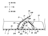
- FIG. 6 shows a state in which a pressing force is applied to the door D from the inside of the vehicle to the outside of the vehicle.
- the posture of the elastic protrusion 24 in this state is referred to as a “second posture”.
- vibration is generated as the vehicle travels, the door D opens and closes, and the like, and when a pressing force acts on the door D from the inside of the vehicle to the outside of the vehicle, the elastic projection 24 first comes into contact with the door D.
- the portion 33 is pressed inside the vehicle by the door panel P.
- the elastic projection 24 is elastically deformed from the first posture to the second posture.
- the portion of the elastic projection 24 that is outside the vehicle from the second contact portion 34 is greatly elastically deformed while maintaining a distance from the contact surface 31 of the stopper 23.
- the length of the elastic protrusion 24 in the vehicle width direction decreases from L1 to L2, and the contact position between the contact surface 31 of the stopper 23 and the second contact portion 34 of the elastic protrusion 24 moves to the outside of the vehicle. (In other words, the second contact portion 34 of the elastic projection 24 moves to the tip end side of the elastic projection 24).
- the elastic protrusion 24 elastically returns from the second posture to the first posture.
- the length of the elastic protrusion 24 in the vehicle width direction increases from L2 to L1
- the contact position between the contact surface 31 of the stopper 23 and the second contact portion 34 of the elastic protrusion 24 moves to the inside of the vehicle. (In other words, the second contact portion 34 of the elastic projection 24 moves to the base end side of the elastic projection 24).
- the elastic projection 24 elastically deforms while maintaining the contact state with the door panel P. As a result, the impact of the pressing force on the door D from the inside of the vehicle to the outside of the vehicle is alleviated, and the generation of abnormal noise is suppressed.
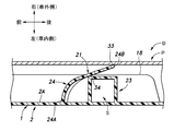
- the door trim 1 configured as described above is arranged so as to face the door panel P.
- the edge portion 4 of the trim main body portion 2 of the door trim 1 is brought into contact with the door panel P, and is attached to the door panel P by a fastening member such as a clip.
- a fastening member such as a clip
- the elastic protrusion 24 is not elastically deformed and faces the stopper 23 at a distance. That is, the second contact portion 34 of the elastic projection 24 does not contact the contact surface 31 of the stopper 23.
- the length of the elastic protrusion 24 and the amount of elastic deformation (deflection amount) become insufficient, and the cushioning action of the elastic protrusion 24 is reduced. There is a risk of doing so.
- the length of the elastic protrusion 24 and the amount of elastic deformation (deflection amount) can be sufficiently secured. Therefore, the buffering action of the elastic protrusion 24 can be enhanced, and the generation of abnormal noise can be effectively suppressed.
- the contact surface 31 of the stopper 23 has an arc shape that swells toward the outside of the vehicle.
- the width W1 of the elastic protrusion 24 in the vertical direction is narrower than the width W2 of the stopper 23 in the vertical direction.
- the vehicle inner end portion 26A of the main wall portion 26 on the front side of the stopper 23 and the vehicle inner end portion 24A of the elastic protrusion 24 face each other with a space in the front-rear direction.
- the elastic protrusion 24 is compared with the case where the car inner end 26A of the main wall 26 on the front side of the stopper 23 and the car inner end 24A of the elastic protrusion 24 are in contact with each other.
- the degree of freedom of elastic deformation can be increased. Therefore, the buffering action of the elastic projection 24 can be further enhanced, and the generation of abnormal noise can be suppressed more effectively.
- the facing distance X between the vehicle inner end portion 26A of the main wall portion 26 on the front side of the stopper 23 and the vehicle inner end portion 24A of the elastic protrusion 24 gradually widens from the lower side to the upper side.
- the stopper 23 includes a pair of main wall portions 26, and the vehicle outer end portions 26B of the pair of main wall portions 26 are connected to each other.
- the elastic projection 24 can be stably supported by the stopper 23 having a simple configuration.
- each main wall portion 26 is formed to be thinner than the portion other than the vehicle inner end portion 26A of each main wall portion 26.
- a recess 30 continuous in the vertical direction is formed on the inner surface of the vehicle inner end portion 26A of each main wall portion 26.
- the stopper 23 further includes a connecting wall portion 28 for connecting the lower end portions of the pair of main wall portions 26.
- the elastic protrusion 24 faces the stopper 23 at a distance.
- the elastic projection 24 is elastically deformed by the door panel P pressing the first contact portion 33, and the second contact portion 34 is attached to the contact surface 31 of the stopper 23. Contact.
- the elastic protrusion 24 can be stably brought into contact with the door panel P and the stopper 23 in a state where the door trim 1 is assembled to the door panel P. Therefore, the buffering action of the elastic projection 24 can be further enhanced, and the generation of abnormal noise can be suppressed more effectively.
- the vehicle inner end portion 24A of the elastic protrusion 24 and the vehicle inner end portion 26A of the main wall portion 26 on the front side of the stopper 23 face each other at a distance.
- the vehicle inner end portion 24A of the elastic projection 24 and the vehicle inner end portion 26A of the main wall portion 26 on the front side of the stopper 23 may be in contact with each other.
- the pair of main wall portions 26 of the stopper 23 are curved so as to bulge toward the outside of the vehicle.
- the main wall portion 26 on the front side of the stopper 23 bulges toward the vehicle outer side.
- the main wall portion 26 on the rear side of the stopper 23 may extend linearly in the vehicle width direction.
- the stopper 23 has a substantially semi-cylindrical shape.
- the stopper 23 may have a square frame shape.
- the shape of the stopper 23 may be any shape as long as the elastic protrusion 24 can be brought into contact with the stopper 23.
- the stopper 23 is hollow, but in other embodiments, the stopper 23 may not be hollow.
- the shape of the elastic protrusion 24 may be any shape as long as the elastic protrusion 24 can be elastically deformed.
- the elastic protrusion 24 has a thin plate shape, but in other embodiments, the elastic protrusion 24 may have a shape other than the thin plate shape (for example, a rod shape).
- two abnormal noise suppressing members 43 are provided on the upper portion of the back surface 2A (the surface on the outer side of the vehicle) of the trim main body 2 at intervals in the front-rear direction. As will be described later, the two abnormal noise suppressing members 43 have a function of suppressing the generation of abnormal noise due to vibration when the vehicle is running, vibration when the door is opened and closed, and the like. In another embodiment, only one abnormal noise suppressing member 43 may be provided in the trim main body portion 2, or three or more abnormal noise suppressing members 43 may be provided in the trim main body portion 2. ..
- each abnormal noise suppressing member 43 is made of a resin material such as polypropylene. Each abnormal noise suppressing member 43 is arranged above the speaker grill 16 and the protector 18 and below the door handle 19. That is, each abnormal noise suppressing member 43 is arranged so as to avoid the speaker grill 16, the protector 18, and the door handle 19. It is preferable that each abnormal noise suppressing member 43 is arranged so as to avoid the heater 10 built in the armrest 6.
- One or both abnormal noise suppressing members 43 may be arranged inside the vehicle (rear surface side) of the pull pocket body 13.
- each abnormal noise suppressing member 43 includes a base portion 44 and a plurality of elastic contact portions 45 supported by the base portion 44.
- each abnormal noise suppressing member 43 protrudes from the back surface 2A of the trim main body portion 2 toward the outside of the vehicle.
- the base portion 44 is formed separately from the back surface 2A of the trim main body portion 2.
- the base portion 44 may be integrally formed with the back surface 2A of the trim main body portion 2.
- the base portion 44 has a cylindrical shape extending in the vehicle width direction.
- the plurality of elastic contact portions 45 of each abnormal noise suppressing member 43 are integrally formed with the base portion 44. In another embodiment, the plurality of elastic contact portions 45 may be formed separately from the base portion 44. The plurality of elastic contact portions 45 are contained within the contour of the base portion 44 when viewed in the vehicle width direction. The plurality of elastic contact portions 45 project from the vehicle outer end portion of the base portion 44 toward the radial inward side of the base portion 44. The plurality of elastic contact portions 45 are arranged at intervals in the circumferential direction of the base portion 44. The plurality of elastic contact portions 45 are arranged radially around the axis 44A of the base portion 44.
- Each elastic contact portion 45 is inclined to the outside of the vehicle toward the tip side (the radial inside of the base portion 44). Therefore, the tip portion 45A of each elastic contact portion 45 is located outside the vehicle from the base end portion 45B and the base portion 44 of each elastic contact portion 45.
- the tip portion 45A of each elastic contact portion 45 is located on the vehicle outer side of the vehicle outer end portion of the protector 18. With the door trim 41 assembled to the door panel P, the tip portion 45A of each elastic contact portion 45 faces the inner surface of the door panel P at a distance.
- the tip portion 45A of each elastic contact portion 45 may be in contact with the vehicle inner surface of the door panel P in a state where the door trim 41 is assembled to the door panel P.
- the width of each elastic contact portion 45 gradually narrows toward the tip end side. Therefore, the width of the tip portion 45A of each elastic contact portion 45 is narrower than the width of the base end portion 45B of each elastic contact portion 45.
- each abnormal noise suppressing member 43 Vibration occurs as the vehicle travels, the door D opens and closes, and when a pressing force acts on the door D from the inside of the vehicle to the outside of the vehicle, the tip 45A of each elastic contact portion 45 hits the door panel P. Each elastic contact portion 45 is elastically deformed in contact with each other. As a result, the impact of the pressing force on the door D from the inside of the vehicle to the outside of the vehicle is alleviated, and the generation of abnormal noise is suppressed.
- each elastic contact portion 45 In a state where the pressing force from the inside of the vehicle to the outside of the vehicle does not act on the door D, the base portion 44 faces the door panel P via a predetermined distance. On the other hand, when each elastic contact portion 45 is elastically deformed by a predetermined amount due to the pressing force acting on the door D from the inside of the vehicle to the outside of the vehicle, the base portion 44 abuts on the door panel P. As a result, the elastic deformation of each elastic contact portion 45 is restricted.
- each abnormal noise suppressing member 43 is attached to the trim main body portion 2.
- each abnormal noise suppressing member 43 is attached to the trim main body portion 2.
- each abnormal noise suppressing member 43 has hinges 57. It is connected via.
- the base portion 44, the trim main body portion 2, and the hinge 57 are integrally formed of the same material (for example, a resin material).
- a fitting protrusion 58 is integrally formed on the base portion 44, and the fitting protrusion 58 is fitted in the fitting hole 59 of the trim main body portion 2.
- each abnormal noise suppressing member 43 is attached to the trim main body portion 2.
- each abnormal noise suppressing member 43 may be formed separately from the trim main body portion 2 (see the first and second examples of the above-mentioned mounting structure), and may be integrated with the trim main body portion 2. It may be formed in (see the third example of the mounting structure described above).
- the vehicle door trim 41 according to the second embodiment is supported by a trim main body 2 provided inside the vehicle of the door panel P, a base 44 protruding from the trim main body 2 toward the outside of the vehicle, and a base 44.
- a plurality of elastic contact portions 45 that abut on the door panel P and elastically deform are provided, and the plurality of elastic contact portions 45 are contained within the contour of the base portion 44 when viewed in the vehicle width direction. As described above, the plurality of elastic contact portions 45 abut on the door panel P and elastically deform, so that the buffering action can be enhanced and the generation of abnormal noise can be effectively suppressed.
- the plurality of elastic contact portions 45 are contained within the contour of the base portion 44 as described above, it is possible to suppress the increase in size of the plurality of elastic contact portions 45. Further, by attaching the resin abnormal noise suppressing member 43 to the trim main body 2, the abnormal noise suppressing member 43 is compared with the case where the abnormal noise suppressing member 43 formed of the non-woven fabric is attached to the trim main body 2. It can be easily attached to the trim main body 2 and the productivity can be improved. Further, by changing the thickness of the plurality of elastic contact portions 45, the cushioning function of each abnormal noise suppressing member 43 can be easily adjusted.
- the base portion 44 has a cylindrical shape, and the plurality of elastic contact portions 45 project from the base portion 44 inward in the radial direction of the base portion 44, and the axial center 44A of the base portion 44 is formed. They are arranged radially around the center.
- each abnormal noise suppressing member 61 includes a base portion 62 and a plurality of elastic contact portions 63 supported by the base portion 62.
- each abnormal noise suppressing member 61 projects from the back surface 2A of the trim main body portion 2 toward the outside of the vehicle.
- the base portion 62 is formed separately from the back surface 2A of the trim main body portion 2.
- the base portion 62 may be integrally formed with the back surface 2A of the trim main body portion 2.
- the base portion 62 has a square cylinder shape extending in the vehicle width direction.
- the base portion 62 has a pair of support wall portions 65 extending in the vertical direction (a front support wall portion 65 and a rear support wall portion 65) and an upper end portion and a lower end portion of the pair of support wall portions 65 extending in the front-rear direction.
- a pair of connecting wall portions 66 (upper connecting wall portion 66 and lower connecting wall portion 66) are provided.
- the base portion 62 may include only a pair of support wall portions 65. That is, the base portion 62 does not necessarily have to be formed in the shape of a square cylinder.
- the pair of support wall portions 65 of the base portion 62 face each other at intervals in the front-rear direction.
- the pair of support wall portions 65 are arranged so as to sandwich each elastic contact portion 63 from both front and rear sides when viewed in the vehicle width direction.
- the pair of support wall portions 65 may be arranged so as to sandwich the elastic contact portions 63 from both the upper and lower sides when viewed in the vehicle width direction.
- the pair of connecting wall portions 66 of the base portion 62 face each other at intervals in the vertical direction.
- the pair of connecting wall portions 66 are arranged so as to sandwich the elastic contact portions 63 from both the upper and lower sides when viewed in the vehicle width direction.
- the pair of connecting wall portions 66 may be arranged so as to sandwich the elastic contact portions 63 from both the front and rear sides when viewed in the vehicle width direction.
- the plurality of elastic contact portions 63 of each abnormal noise suppressing member 61 are integrally formed with the base portion 62. In another embodiment, the plurality of elastic contact portions 63 may be formed separately from the base portion 62. The plurality of elastic contact portions 63 are contained within the contour of the base portion 62 when viewed in the vehicle width direction. The plurality of elastic contact portions 63 are arranged in the vertical direction.
- Each elastic contact portion 63 includes a pair of contact pieces 68.
- Each contact piece 68 extends from the vehicle outer end of each support wall portion 65 of the base portion 62 toward the front-rear center line Y of the base portion 62.
- the tip portion 68A of one contact piece 68 and the tip portion 68A of the other contact piece 68 face each other with a distance in the front-rear direction.
- the vertical width of each contact piece 68 is constant from the base end side to the tip end side. Therefore, the vertical width of the tip end portion 68A of each contact piece 68 is equal to the vertical width of the base end portion 68B of each contact piece 68.
- Each contact piece 68 is inclined to the outside of the vehicle toward the tip side (Y side of the front-rear center line of the base portion 62). Therefore, the tip end portion 68A of each contact piece 68 is located outside the vehicle from the base end portion 68B and the base portion 62 of each contact piece 68. The tip end portion 68A of each contact piece 68 is located outside the vehicle side of the vehicle side end portion of the protector 18. With the door trim 41 assembled to the door panel P, the tip 68A of each contact piece 68 faces the inner surface of the door panel P at a distance. In another embodiment, the tip end portion 68A of each contact piece 68 may be in contact with the vehicle inner surface of the door panel P in a state where the door trim 41 is assembled to the door panel P.
- the degree of inclination of each contact piece 68 toward the outside of the vehicle is different for each elastic contact portion 63.
- the degree of inclination of each contact piece 68 toward the outside of the vehicle is the largest in the elastic contact portion 63 at the center in the vertical direction and the smallest in the elastic contact portions 63 at both ends in the vertical direction.
- the vehicle door trim 41 according to the third embodiment is supported by a trim main body 2 provided inside the vehicle of the door panel P, a base portion 62 protruding from the trim main body 2 toward the outside of the vehicle, and a base portion 62.
- a plurality of elastic contact portions 63 that abut on the door panel P and elastically deform are provided, and the plurality of elastic contact portions 63 are contained within the contour of the base portion 62 when viewed in the vehicle width direction.
- the plurality of elastic contact portions 63 abut on the door panel P and elastically deform, so that the buffering action can be enhanced and the generation of abnormal noise can be effectively suppressed.
- the plurality of elastic contact portions 63 are contained within the contour of the base portion 62 as described above, it is possible to suppress the increase in size of the plurality of elastic contact portions 63.
- the base portion 62 includes a pair of support wall portions 65 extending in the vertical direction (first direction orthogonal to the vehicle width direction), and the plurality of elastic contact portions 63 are formed from the support wall portions 65 to the base portion. It is provided with a pair of contact pieces 68 extending toward the front-rear center line Y (center line in the vehicle width direction and the second direction orthogonal to the first direction) of 62.
- each abnormal noise suppressing member 71 includes a base portion 72 and an elastic contact portion 73 supported by the base portion 72.
- each abnormal noise suppressing member 71 protrudes from the back surface 2A of the trim main body portion 2 toward the outside of the vehicle.
- the base portion 72 is formed separately from the back surface 2A of the trim main body portion 2.
- the base portion 72 may be integrally formed with the back surface 2A of the trim main body portion 2.
- the base portion 72 has a cylindrical shape extending in the vehicle width direction.
- each abnormal noise suppressing member 71 is integrally formed with the base portion 72.
- the elastic contact portion 73 may be formed separately from the base portion 72.
- the elastic contact portion 73 is within the contour of the base portion 72 when viewed in the vehicle width direction.
- the elastic contact portion 73 includes an elastic piece 75 arranged radially inside the base portion 72 at a distance from the base portion 72, and a pair of connecting pieces 76 connecting the base portion 72 and the elastic piece 75. ing. In another embodiment, the elastic contact portion 73 may include only one connecting piece 76, or the elastic contact portion 73 may include three or more connecting pieces 76. Further, in still another embodiment, the elastic contact portion 73 does not include the connecting piece 76, and the base portion 72 and the elastic piece 75 may be directly connected to each other.
- the elastic piece 75 of the elastic contact portion 73 has a spiral shape centered on the axial center 72A of the base portion 72 when viewed in the vehicle width direction.
- the elastic piece 75 is inclined to the outside of the vehicle toward the tip end side (the radial inside of the base portion 72). Therefore, the tip portion 75A of the elastic piece 75 is located outside the vehicle from the base end portion 75B of the elastic piece 75, each connecting piece 76, and the base portion 72.
- the tip portion 75A of the elastic piece 75 is located outside the vehicle side of the vehicle side end portion of the protector 18. With the door trim 41 assembled to the door panel P, the tip portion 75A of the elastic piece 75 faces the inner surface of the door panel P at a distance.
- the tip of the elastic piece 75 may be in contact with the inner surface of the door panel P in a state where the door trim 41 is assembled to the door panel P.
- the pair of connecting pieces 76 of the elastic contact portion 73 are arranged on opposite sides of the axial center 72A of the base portion 72. Each connecting piece 76 extends along the radial direction of the base portion 72. Each connecting piece 76 connects the outer end portion of the base portion 72 to the base end portion 75B of the elastic piece 75.
- the vehicle door trim 41 according to the fourth embodiment is supported by a trim main body 2 provided inside the vehicle of the door panel P, a base portion 72 protruding from the trim main body 2 toward the outside of the vehicle, and a base portion 72.
- the elastic contact portion 73 is provided with an elastic contact portion 73 that abuts on the door panel P and elastically deforms, and the elastic contact portion 73 is contained within the contour of the base portion 72 when viewed in the vehicle width direction. As described above, the elastic contact portion 73 abuts on the door panel P and elastically deforms, so that the buffering action can be enhanced and the generation of abnormal noise can be effectively suppressed. Further, since the elastic contact portion 73 is contained within the contour of the base portion 72 as described above, it is possible to suppress the increase in size of the elastic contact portion 73.
- the base portion 72 has a cylindrical shape
- the elastic contact portion 73 includes an elastic piece 75 arranged radially inside the base portion 72, and the elastic piece 75 is viewed in the vehicle width direction.
- the base portion 72 has a spiral shape centered on the axis 72A.
- the door trim 1 is an example of an interior part
- the door panel P is an example of an exterior part
- the parts other than the door trim 1 may be used as an example of the interior parts
- the parts other than the door panel P may be used as an example of the exterior parts. That is, the present invention can be widely applied not only to the door D but also to a place other than the door D on the side of the vehicle body (for example, a support such as a B pillar).
- the armrest 81 bulges from an intermediate portion in the vertical direction of the main surface portion 3 of the trim main body portion 2.
- the arm rest 81 functions as an armrest for the occupant to place his / her arm.
- the armrest 81 extends in the front-rear direction.
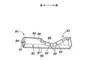
- the armrest 81 includes a resin base material 82, a skin 83 that covers the surface of the base material 82 (the inner surface of the vehicle), and a pair of hooks 84 (upper side) that are attached to the skin 83.
- the hook 84 and the lower hook 84) are provided.
- the armrest 81 may be provided with only one hook 84, or the armrest 81 may be provided with three or more hooks 84.
- the base material 82 of the armrest 81 has a long shape in the front-rear direction.
- the base material 82 includes an upper wall portion 86 extending in the vehicle width direction and a side wall portion 87 extending downward from the vehicle inner end portion of the upper wall portion 86.
- a recess 88 is formed in the front portion of the upper wall portion 86. Therefore, the left-right width of the front portion of the upper wall portion 86 is narrower than the left-right width of the rear portion of the upper wall portion 86.
- a plurality of engaging protrusions 90 are arranged in the front-rear direction on the back surface (lower surface) of the front portion of the upper wall portion 86.
- a pair of bosses 91 project from the back surfaces (outside surfaces of the vehicle) of both front and rear ends of the side wall portion 87.
- the skin 83 of the armrest 81 has a long shape in the front-rear direction and covers the surface of the base material 82.
- a plurality of engaging holes 93 are arranged in the front-rear direction in the front portion of the skin 83.
- the plurality of engaging holes 93 are engaged with the plurality of engaging protrusions 90 of the upper wall portion 86 of the base material 82.
- the front and rear ends of the skin 83 are folded back at the front and rear ends of the base material 82 to reach the back surface of the base material 82.
- a pair of mounting holes 94 are provided at both front and rear ends of the skin 83.
- the pair of mounting holes 94 are engaged with the pair of bosses 91 of the side wall portion 87 of the base material 82.
- the pair of hooks 84 of the armrest 81 are J-shaped.
- the pair of hooks 84 are attached to both sides of the skin 83 in the width direction.
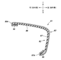
- the upper hook 84 is engaged with the vehicle outer edge portion 86A at the rear portion of the upper wall portion 86 of the base material 82.
- the lower hook 84 is engaged with the lower edge portion 87A of the side wall portion 87 of the base material 82.
- the upper hook 84 is engaged with the vehicle outer edge portion 86A at the rear of the upper wall portion 86 of the base material 82, and the lower hook 84 is engaged with the lower edge portion 87A of the side wall portion 87 of the base material 82. Match. This completes the attachment of the skin 83 to the base material 82.
- the armrest 81 includes a base material 82, a skin 83 that covers the surface of the base material 82, and at least one hook 84 (engagement member) attached to the skin 83, and the hook 84. Is engaged with the base material 82, so that the skin 83 is attached to the base material 82.
- the skin 83 can be attached to the base material 82 without using an adhesive. Therefore, the man-hours for attaching the skin 83 to the base material 82 can be reduced, and the burden on the environment can be reduced. Further, since complicated bonding work is not required, the work of attaching the skin 83 to the base material 82 can be simplified, and the work of the product (that is, the armrest 81) can be suppressed from being varied. ..
- the skin 83 is attached to the base material 82 by engaging the pair of hooks 84 attached to the skin 83 with the pair of edges of the base material 82.
- the skin 83 can be attached to the base material 82 without any special processing on the base material 82.
- the skin 83 is attached to the base material 82 by engaging the pair of hooks 84 attached to the skin 83 with the pair of edges of the base material 82.
- the skin 83 may be attached to the base material 82 by the hook-and-loop fastener 96 provided in the overlapping portion of the base material 82 and the skin 83.
- a pair of hooks 84 attached to the skin 83 engages with a pair of through holes 97 provided in the base material 82 to form the base material 82.
- the skin 83 may be attached.
- a pair of fitting pieces 98 attached to the skin 83 is partially formed in the pair of fitting grooves 99 provided on the back surface of the base material 82.
- the skin 83 may be attached to the base material 82 by fitting together with the base material 82.
- the door trim 101 (an example of an interior component) according to the sixth embodiment has a trim main body 102 (an example of the main body) provided inside the vehicle of the door panel P (an example of an exterior component). ing.
- the trim main body portion 102 has a main surface portion 103 facing in the vehicle width direction and an edge portion 104 corresponding to the peripheral edge of the main surface portion 103.
- the edge portion 104 extends from the end portion of the main surface portion 103 toward the outside of the vehicle. Further, the outer end portion of the edge portion 104 is in contact with the door panel P, and is attached to the door panel P via a fastening member such as a clip.
- the door trim 101 is made of resin.
- the door trim 101 has an armrest 106 having an armrest upper wall 107 that bulges inward from the trim body 102 and faces up and down, and an armrest side wall 108 that extends downward from the inner end of the armrest upper wall 107. ing.
- the armrest 106 bulges from an intermediate portion in the vertical direction of the main surface portion 103.
- the armrest 106 functions as an armrest for the occupant to place his / her arm.
- the armrest upper wall 107 extends substantially horizontally from the main surface portion 103 to the inside of the vehicle.
- the rear end of the armrest side wall 108 is inclined toward the rear to the outside of the vehicle.
- a switch portion 109 is provided on the front portion of the armrest upper wall 107 for the occupant to open and close the window.
- a pull pocket mounting hole 110 and a plurality of fastening holes 112 are formed in the rear portion of the armrest upper wall 107.
- the pull pocket mounting hole 110 penetrates the armrest upper wall 107 up and down.
- the door trim 101 has a box shape that opens upward, and has a pull pocket body 113 that defines a pull pocket space 114 that is recessed downward from the armrest upper wall 107.
- the pull pocket body 113 is arranged in the pull pocket mounting hole 110.
- the pull pocket body 113 functions as a gripping portion for gripping when the occupant opens and closes the door D.
- the pull pocket body 113 is made of resin.
- the pull pocket body 113 has a pocket portion 115 and a flange portion 122.
- the pocket portion 115 of the pull pocket body 113 includes a pocket bottom wall 116 whose surface faces in the vertical direction, and a pocket inner wall 117 whose surface extends upward from the vehicle inner end of the pocket bottom wall 116 and whose surface faces in the vehicle width direction.
- a pocket outer wall 118 that extends upward from the vehicle outer end of the pocket bottom wall 116 and whose surface faces in the vehicle width direction, and a pocket that extends upward from the front end of the pocket bottom wall 116 and whose surface faces in the front-rear direction. It has a front wall 119 and a pocket rear wall 120 that extends upward from the rear end of the pocket bottom wall 116 and whose surface faces in the front-rear direction.
- a plurality of fastening pieces 125 are provided on the pocket bottom wall 116.
- the fastening piece 125 extends downward from the lower surface of the pocket bottom wall 116.
- the fastening piece 125 has an insertion hole for inserting a fastening member such as a bolt, and is fastened to the armrest 106 by the fastening member.
- An overhang portion 124 that bulges toward the outside of the vehicle is formed on the upper part of the inner wall wall 117 of the pocket.
- the overhang portion 124 functions as a hooking portion for the occupant to hook his / her finger on the inner wall wall 117 of the pocket.
- the lower part of the overhang portion 124 is inclined downward toward the inside of the vehicle.
- the inner surface of the pocket inner wall 117 faces the outer surface of the armrest side wall 108 in the vehicle width direction.
- the flange portion 122 of the pull pocket body 113 extends from the upper end portion of the pocket portion 115 in the direction opposite to the pull pocket space 114 in the vehicle width direction.
- the flange portion 122 is arranged at the peripheral edge portion of the pull pocket mounting hole 110 on the upper surface of the armrest upper wall 107.
- a plurality of locking claws 126 extending downward are formed on the lower surface of the flange portion 122.
- the flange portion 122 is coupled to the armrest upper wall 107 by hooking each locking claw 126 to the fastening hole 112.
- a cover member may be provided to cover the flange portion 122 in order to enhance aesthetics and functionality.
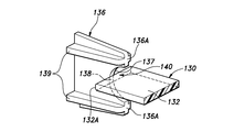
- One of the armrest side wall 108 and the pocket inner wall 117 has at least one protrusion 130 protruding toward the other of the armrest side wall 108 and the pocket inner wall 117. Further, the other side of the armrest side wall 108 and the pocket inner wall 117 has a receiving portion 136 having at least one receiving surface 137 abutting on or close to the protrusion 130 in the vehicle width direction.
- the protrusion 130 is provided on the inner wall wall 117 of the pocket, and the receiving portion 136 is provided on the side wall 108 of the armrest.
- the protrusion 130 is formed in a plate shape and extends in a direction orthogonal to the vehicle width direction.
- the receiving portion 136 is formed in a plate shape and extends in a direction orthogonal to the protrusion 130.
- the protrusion 130 projects from the pocket inner wall 117 toward the inside of the vehicle.
- the protrusion 130 has a protrusion base 131 and a protrusion tip 132.
- the protrusion 130 may be flexible.
- the protrusion 130 is integrally formed with the pull pocket body 113.
- the protrusion base 131 protrudes from the inner wall wall 117 of the pocket toward the inside of the vehicle.
- the protrusion base 131 is formed in a substantially box shape.
- the end surface 131A on the inside of the vehicle of the protrusion base 131 is parallel to the pocket inner wall 117.
- the protrusion tip 132 protrudes toward the inside of the vehicle from the end surface 131A inside the vehicle of the protrusion base 131.
- the protrusion tip 132 is formed in a plate shape extending in the vehicle width direction and the front-rear direction.
- the length of the protrusion tip portion 132 in the front-rear direction is shorter than the length of the protrusion base portion 131 in the front-rear direction.
- the vertical length of the protrusion tip 132 is shorter than the vertical length of the protrusion base 131.
- the protrusion tip 132 may be provided approximately in the center of the end surface 131A inside the vehicle of the protrusion base 131.
- the tip 132A of the protrusion tip 132 may be chamfered.
- the receiving portion 136 projects from the armrest side wall 108 toward the outside of the vehicle and faces the protrusion 130 in the vehicle width direction.
- the receiving portion 136 is formed in a plate shape and extends in the vehicle width direction and the vertical direction. The vertical width of the receiving portion 136 gradually decreases toward the outside of the vehicle.
- the receiving portion 136 is integrally formed with the armrest side wall 108.
- the receiving portion 136 has a receiving surface 137 inclined with respect to the vehicle width direction.
- the receiving surface 137 is provided at a position in contact with or close to the protrusion tip 132 in the vehicle width direction.
- the receiving surface 137 may be in contact with the protrusion tip 132.
- the receiving surface 137 may be provided at the center of the receiving portion 136 on the inner side of the vehicle in the vertical direction of the tip edge 136A.
- the receiving portion 136 has a groove portion 140 at its tip edge 136A.
- the groove 140 is recessed toward the armrest side wall 108, that is, toward the inside of the vehicle.
- the groove portion 140 extends in the front-rear direction and penetrates the receiving portion 136 in the front-rear direction.
- the receiving surface 137 is formed in the groove 140. Specifically, the receiving surface 137 forms part of the wall surface that defines the groove 140.
- the bottom of the groove 140 is provided with a bottom surface 138 facing the vehicle width direction.
- the bottom surface 138 is smoothly connected to the receiving surface 137.
- the groove portion 140 has an arc-shaped cross section. It is preferable that the receiving surface 137 and the bottom surface 138 extend in an arc shape and are connected to each other.
- the receiving portion 136 may have at least one reinforcing member 139. Thereby, the rigidity of the receiving portion 136 can be improved.
- the reinforcing member 139 may be a rib connecting the receiving portion 136 and the armrest side wall 108.
- the reinforcing member 139 may be formed in a plate shape orthogonal to the receiving portion 136.
- the pull pocket body 113 is gripped by an occupant when the door D is opened and closed.
- the occupant hooks his finger on the inner wall wall 117 of the pocket and pulls it inside the vehicle.
- the inner wall wall 117 of the pocket receives a load from the occupant and elastically deforms inside the vehicle.
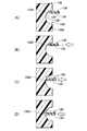
- the protrusion tip 132 when no load is applied to the pocket inner wall 117 from the occupant, the protrusion tip 132 is arranged at a position abutting or in close proximity to the receiving surface 137. .. As shown in FIG. 26B, even if the relative position between the protrusion tip 132 and the receiving surface 137 changes due to a manufacturing error, the protrusion tip 132 is deformed and the protrusion tip 132 hits the receiving surface 137. It is good to be in contact. Further, as shown in FIG. 26 (A), the protrusion tip 132 may be separated from the receiving surface 137 to the outside of the vehicle. At this time, the tip 132A of the protrusion tip 132 may be located in the groove 140.
- the pocket inner wall 117 is moved inside the vehicle.
- the tip portion 132 of the protrusion moves to the inside of the vehicle and comes into contact with the receiving surface 137 (see FIG. 26 (B)).
- the protrusion tip 132 slides on the receiving surface 137 and moves toward the bottom surface 138 (see FIG. 26 (C)).
- the tip 132A of the protrusion tip 132 reaches the bottom surface 138 (see FIG. 26 (D)).
- the bottom surface 138 is a surface facing the vehicle width direction, when the protrusion tip 132 reaches the bottom surface 138, the movement of the protrusion tip 132 toward the inside of the vehicle is restricted by the bottom surface 138. As a result, the pocket inner wall 117 is supported by the armrest side wall 108 via the protrusion 130 and the receiving portion 136, and the deformation of the pocket inner wall 117 to the inside of the vehicle is suppressed. When the occupant stops pulling the pocket inner wall 117, the pocket inner wall 117 is restored by the elastic force, and the protrusion tip 132 returns to the initial position shown in FIG. 26 (A) or FIG. 26 (B).
- the receiving surface 137 corresponding to the protrusion tip 132 is inclined with respect to the vehicle width direction, it is easy to maintain the state in which the protrusion tip 132 and the receiving surface 137 are in contact with each other even when a manufacturing error occurs. As a result, when the pull pocket body 113 is deformed, the collision between the protrusion 130 and the receiving surface 137 is avoided, and the generation of abnormal noise is suppressed.
- the receiving surface 137 is inclined with respect to the vehicle width direction, so that when the protrusion tip 132 abuts on the receiving surface 137, the protrusion tip The 132 is guided in the direction along the receiving surface 137, and the momentum of the collision between the protrusion tip 132 and the receiving surface 137 is reduced. As a result, the generation of abnormal noise is suppressed.
- the protrusion 130 has a simple structure and can be integrally molded with the pull pocket body 113. Further, the receiving portion 136 has a simple structure and can be integrally molded with the armrest 106 and the trim main body portion 102. As a result, the manufacturing cost of the door trim 101 can be reduced.
- the protrusion tip portion 132 and the receiving surface 137 are arranged orthogonally, and the protrusion tip portion 132 stably abuts and slides on the receiving surface 137. Can move.
- the protrusion tip 132 slides on the receiving surface 137, the protrusion 130 bends, so that the load applied to the receiving surface 137 by the protrusion 130 is reduced, and the generation of abnormal noise is further suppressed.
- the tip 132A of the protrusion tip 132 is chamfered, the friction with the receiving surface 137 is reduced. As a result, it is possible to reduce the generation of frictional noise and the wear of the protrusion tip 132 and the receiving surface 137. Further, since the receiving surface 137 is formed in the groove portion 140 and the protrusion tip portion 132 plunges into the groove portion 140, the movement of the protrusion tip portion 132 is restricted by the groove portion 140.
- the receiving surface 137 has an arcuate cross section, the reaction force generated when the protrusion 130 is pressed smoothly increases as the protrusion tip 132 slides on the receiving surface 137. do. As a result, when the protrusion 130 comes into contact with the bottom surface 138, abnormal noise is less likely to occur.
- the groove 140 has an arcuate cross section, but in other embodiments, the groove 140 has a V-shaped (triangular) cross section as shown in FIG. 27. May be.
- the protrusion 130 may be provided on the armrest side wall 108, and the receiving portion 136 may be provided on the pocket inner wall 117.
- one of the armrest side wall 108 and the pocket inner wall 117 has a plurality of protrusions 130, and the other of the armrest side wall 108 and the pocket inner wall 117 has a vehicle width direction with respect to each of the protrusions 130.
- Each of the protrusions 130 may be provided with a connecting portion 133 for connecting to each other.
- the two protrusions 130 are each formed in a plate shape and face each other in parallel.
- the connecting portion 133 connects the side portions of the two protrusions 130 that correspond to each other.
- the connecting portion 133 may extend in the vehicle width direction along the protrusion 130. When viewed from the vehicle width direction, the two protrusions 130 and the connecting portion 133 are arranged in a U shape.
- the connecting portion 133 is arranged at a position where it does not abut on the receiving portion 136 when the protrusion tip portion 132 is in contact with the receiving surface 137.
- the connecting portion 133 improves the rigidity of the protrusion 130.
- the two protrusions 130 have a surface facing in the vertical direction and are arranged vertically apart from each other.
- the connecting portion 133 extends in the vertical direction to connect the two protrusions 130.
- the two receiving portions 136 facing the two protrusions 130 are each formed in a plate shape, and the surfaces thereof face in the front-rear direction.
- the two receiving portions 136 are arranged side by side in the vertical direction and are connected to each other.
- Each receiving portion 136 has a groove portion 140 on the tip edge 136A on the outer side of the vehicle.
- the groove portion 140 has the same configuration as the groove portion 140 according to the sixth embodiment.
- the two groove portions 140 have an arcuate cross-sectional shape when viewed from the front-rear direction.
- a receiving surface 137 is formed in each of the groove portions 140.
- the inclination direction of the receiving surface 137 with which each protrusion 130 abuts may be different.
- the upper receiving surface 137 with which the upper protrusion 130 abuts is inclined upward toward the inside of the vehicle.
- the lower receiving surface 137 with which the lower protrusion 130 abuts is inclined downward toward the inside of the vehicle.
- the upper receiving surface 137 may be arranged in the lower part of the upper groove portion 140, and the lower receiving surface 137 may be arranged in the upper part of the lower groove portion 140. According to this configuration, when each protrusion 130 moves to the inside of the vehicle, the upper protrusion 130 is guided upward to the upper receiving surface 137, and the lower protrusion 130 is guided downward to the lower receiving surface 137. Will be done.
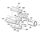
- one of the armrest side wall 108 and the pocket inner wall 117 has a plurality of protrusions 130, and the other of the armrest side wall 108 and the pocket inner wall 117 has a vehicle with respect to each of the protrusions 130. It has one or more receiving portions 136 at positions facing each other in the width direction. Further, each of the protrusions 130 is arranged in the circumferential direction about the center line A. Each of the protrusions 130 is formed in an arc shape centered on the center line A, and a slit 134 is formed between the adjacent protrusions 130.
- each protrusion 130 is arranged side by side in the circumferential direction around the center line A extending in the vehicle width direction on the pocket inner wall 117.
- Each protrusion 130 extends from the inner wall wall 117 of the pocket to the inside of the vehicle.
- each protrusion 130 is formed in an arc shape centered on the center line A when viewed from the vehicle width direction.
- the bases of the protrusions 130 may be connected to each other by a connecting portion 133 extending in the circumferential direction about the center line A.
- These protrusions 130 are formed by providing a plurality of slits 134 in the tubular body 135 centered on the center line A.
- the four receiving portions 136 corresponding to the four protrusions 130 are each formed in a plate shape and extend in the radial direction about the center line A. Further, the four receiving portions 136 are orthogonal to the corresponding protrusions 130 when viewed from the vehicle width direction.
- the four receiving portions 136 are connected to each other at positions overlapping with the center line A, and are formed in a + shape (cross) when viewed from the vehicle width direction.
- a groove 140 is formed at the tip edge 136A on the outer side of the vehicle of each receiving portion 136.
- a receiving surface 137 is formed on the wall surface of each groove 140. The receiving surfaces 137 have different inclination directions from each other.
- the receiving surface 137 of the receiving portion 136 arranged on the upper side of the center line A is inclined upward toward the inside of the vehicle, and the receiving surface 137 of the receiving portion 136 arranged on the front side of the center line A is forward toward the inside of the vehicle.
- the receiving surface 137 of the receiving portion 136 arranged on the lower side of the center line A is inclined downward toward the inside of the vehicle, and the receiving surface 137 of the receiving portion 136 arranged on the rear side of the center line A is inclined to It is tilted backward toward the inside of the car.
- the side protrusion 130 is guided downward to the lower receiving surface 137, and the rear protrusion 130 is guided rearward to the rear receiving surface 137. Since the directions in which the four protrusions 130 are guided are opposite to each other on a plane orthogonal to the vehicle width direction in this way, it is difficult for the pull pocket body 113 to move in the direction orthogonal to the vehicle width direction due to the load received from the receiving portion 136. Become.
- the plurality of protrusions 130 are defined by providing the tubular body 135 with the plurality of slits 134, the plurality of protrusions 130 and the receiving portion 136 can be arranged efficiently in space.
- the vehicle door D according to the ninth embodiment has a first member and a second member facing each other in the vehicle width direction, and one of the first member and the second member is a first member and a second member.
- the other of the first member and the second member has at least one receiving portion 136 having a receiving surface 137 that abuts or is close to the protrusion 130 in the vehicle width direction.
- the receiving surface 137 is inclined with respect to the vehicle width direction.
- the combination of the first member and the second member may be, for example, the door panel P and the door trim 101, the first portion of the door trim 101 and the second portion of the door trim 101, and the like.
- the first portion of the door trim 101 may be, for example, the pull pocket body 113 and the second portion may be the armrest 106.
- the combination of the first member and the second member includes the main surface portion 103 of the door panel P and the door trim 101, the armrest 106 of the door panel P and the door trim 101, the pull pocket body 113 of the door panel P and the door trim 101, and the like.
- FIG. 31 shows an example in which the first member is a metal door panel P and the second member is a resin door trim 101 coupled to the door panel P.
- a protrusion 130 is provided on the door panel P, and a receiving portion 136 is provided on the door trim 101.
- the configuration of the protrusion 130 and the receiving portion 136 the configuration of the protrusion 130 and the receiving portion 136 according to the sixth to eighth embodiments may be incorporated.
- the protrusion 130 and the receiving portion 136 may be formed of resin.
- the protrusion 130 is formed in a plate shape and extends in a direction orthogonal to the vehicle width direction.
- the receiving portion 136 is formed in a plate shape and extends in a direction orthogonal to the protrusion 130.
- the protrusion 130 may be formed of resin and may be bonded to the inner surface of the door panel P by a fastening member such as a clip or a screw or an adhesive.
- the protrusion base 131 projects from the door panel P toward the inside of the vehicle.
- the protrusion base 131 is formed in a substantially box shape.
- the end surface 131A on the inside of the vehicle of the protrusion base 131 is parallel to the door trim 101.
- the receiving portion 136 projects from the door trim 101 toward the outside of the vehicle and faces the protrusion 130 in the vehicle width direction.
- the receiving portion 136 is formed in a plate shape and extends in the vehicle width direction and the vertical direction.
- the receiving portion 136 may be formed of resin and integrally formed on the side surface of the door trim 101 on the outer side of the vehicle.
- One aspect of the present invention is a vehicle door (D), which has a first member and a second member facing each other in the vehicle width direction, and one of the first member and the second member is the first member. It has at least one protrusion (130) protruding toward the other of the one member and the second member, and the other of the first member and the second member abuts or approaches the protrusion in the vehicle width direction. It has at least one receiving portion (136) having a receiving surface (137), and the receiving surface is inclined with respect to the vehicle width direction. According to this aspect, it is possible to suppress the generation of collision noise between members in a vehicle door.
- the protrusions are likely to be maintained in contact with the receiving surface by sliding on the receiving surface.
- the receiving surface is inclined with respect to the vehicle width direction, so that when the protrusion collides with the receiving surface, the protrusion follows the receiving surface. It is guided in the direction and the generation of collision noise is suppressed.
- the first member is a metal door panel (P)
- the second member is a resin door trim (101) coupled to the door panel. According to this configuration, it is possible to suppress the generation of collision noise between the door panel and the door trim in the vehicle door.
- a door trim which is a trim main body portion (102) provided inside the vehicle of a door panel, and an armrest upper wall (107) that bulges inward from the trim main body portion and faces up and down.
- an armrest (106) having an armrest side wall (108) extending downward from the inner end of the armrest upper wall, and a pull pocket space recessed downward from the armrest upper wall having a box shape opened upward. It has a pull pocket body (113) defining 114), and the pull pocket body has a pocket inner wall (117) facing the armrest side wall in the vehicle width direction, and the armrest side wall and the pocket inner wall.
- One has at least one protrusion that projects toward the other of the armrest side wall and the pocket inner wall, and the other of the armrest side wall and the pocket inner wall abuts or is close to the protrusion in the vehicle width direction. It has at least one receiving portion having a surface, and the receiving surface is inclined with respect to the vehicle width direction. According to this aspect, it is possible to suppress the generation of collision noise between the pull pocket body and the armrest in the door trim. Even if the relative position between the protrusion and the receiving portion changes due to a manufacturing error, the protrusion can be easily maintained in contact with the receiving surface by sliding on the receiving surface.
- the receiving surface is inclined with respect to the vehicle width direction, so that when the protrusion collides with the receiving surface, the protrusion follows the receiving surface. It is guided in the direction and the generation of collision noise is suppressed.
- the protrusion is formed in a plate shape and extends in a direction orthogonal to the vehicle width direction
- the receiving portion is formed in a plate shape and extends in a direction orthogonal to the protrusion. It is good. According to this configuration, the protrusions and the receiving surface are arranged orthogonally to each other, so that the protrusions can be reliably in contact with the receiving surface.
- the receiving portion has a groove portion (140) at the tip edge (136A) thereof, and the receiving surface is formed in the groove portion. According to this configuration, since the receiving surface is formed in the groove portion and the protrusion penetrates into the groove portion, the movement of the protrusion is restricted by the groove portion.
- the groove portion may have an arc-shaped cross section. According to this configuration, as the protrusion slides on the receiving surface, the reaction force generated when the protrusion is pressed is smoothly increased from the receiving surface. Therefore, when the protrusion abuts on the bottom surface, collision noise is less likely to occur.
- a plurality of the protrusions are provided and a plurality of the receiving portions are provided. According to this configuration, the load applied by one protrusion to one receiving portion is reduced, and the generation of collision noise is suppressed.
- the two adjacent protrusions are connected to each other by the connecting portion (133). According to this configuration, the rigidity of the protrusion can be improved.
- each of the protrusions is arranged in the circumferential direction centered on the predetermined center line (A) when viewed from the vehicle width direction. According to this configuration, the protrusions can be closely arranged to save space.
- each of the protrusions is formed in an arc shape centered on the center line, and a slit (134) is formed between the two adjacent protrusions. According to this configuration, a plurality of protrusions and receiving portions can be arranged in a space-efficient manner.
- the protrusion has flexibility. According to this configuration, the bending of the protrusion reduces the load applied to the receiving surface by the protrusion and suppresses the generation of collision noise.
- the tip (132A) of the protrusion is chamfered. According to this configuration, the friction generated when the protrusion slides on the receiving surface is reduced, and the generation of frictional noise and the wear of the protrusion and the receiving surface can be reduced.
- the receiving portion has at least one reinforcing member (139). According to this configuration, the rigidity of the receiving portion can be improved.
- the present invention can be widely modified without being limited to the above embodiment.
- the shapes and numbers of the protrusions 130 and the receiving portions 136 may be appropriately changed.
- the groove portion 140 is not an essential configuration and may be omitted.
- the receiving surface 137 may be formed in the entire area of the tip edge 136A of the receiving portion 136.
- the door trim 101 is an example of an interior part
- the door panel P is an example of an exterior part
- the parts other than the door trim 101 may be used as an example of the interior parts
- the parts other than the door panel P may be used as an example of the exterior parts. That is, the present invention can be widely applied not only to the door D but also to a place other than the door D on the side of the vehicle body (for example, a support such as a B pillar).
Landscapes
- Engineering & Computer Science (AREA)
- Mechanical Engineering (AREA)
- Vehicle Interior And Exterior Ornaments, Soundproofing, And Insulation (AREA)
Priority Applications (1)
| Application Number | Priority Date | Filing Date | Title |
|---|---|---|---|
| JP2022522214A JP7617448B2 (ja) | 2020-05-15 | 2021-05-14 | 車両用のドアトリム及び車両用の内装部品 |
Applications Claiming Priority (6)
| Application Number | Priority Date | Filing Date | Title |
|---|---|---|---|
| US202063025591P | 2020-05-15 | 2020-05-15 | |
| US63/025,591 | 2020-05-15 | ||
| JP2020-155467 | 2020-09-16 | ||
| JP2020155467 | 2020-09-16 | ||
| US202163157027P | 2021-03-05 | 2021-03-05 | |
| US63/157,027 | 2021-03-05 |
Publications (1)
| Publication Number | Publication Date |
|---|---|
| WO2021230345A1 true WO2021230345A1 (ja) | 2021-11-18 |
Family
ID=78524516
Family Applications (1)
| Application Number | Title | Priority Date | Filing Date |
|---|---|---|---|
| PCT/JP2021/018364 Ceased WO2021230345A1 (ja) | 2020-05-15 | 2021-05-14 | 車両用のドアトリム及び車両用の内装部品 |
Country Status (2)
| Country | Link |
|---|---|
| JP (1) | JP7617448B2 (https=) |
| WO (1) | WO2021230345A1 (https=) |
Citations (5)
| Publication number | Priority date | Publication date | Assignee | Title |
|---|---|---|---|---|
| JPH0467516U (https=) * | 1990-10-19 | 1992-06-16 | ||
| JPH09220983A (ja) * | 1996-02-19 | 1997-08-26 | Nissan Motor Co Ltd | 自動車用車体構造 |
| JP2001171348A (ja) * | 1999-12-15 | 2001-06-26 | Suzuki Motor Corp | 樹脂製トリムの構造 |
| JP2012171508A (ja) * | 2011-02-22 | 2012-09-10 | Toyota Boshoku Corp | 車両用内装材 |
| JP2017030372A (ja) * | 2015-07-28 | 2017-02-09 | 豊田鉄工株式会社 | 重ね合わせ複合内装部品 |
-
2021
- 2021-05-14 WO PCT/JP2021/018364 patent/WO2021230345A1/ja not_active Ceased
- 2021-05-14 JP JP2022522214A patent/JP7617448B2/ja active Active
Patent Citations (5)
| Publication number | Priority date | Publication date | Assignee | Title |
|---|---|---|---|---|
| JPH0467516U (https=) * | 1990-10-19 | 1992-06-16 | ||
| JPH09220983A (ja) * | 1996-02-19 | 1997-08-26 | Nissan Motor Co Ltd | 自動車用車体構造 |
| JP2001171348A (ja) * | 1999-12-15 | 2001-06-26 | Suzuki Motor Corp | 樹脂製トリムの構造 |
| JP2012171508A (ja) * | 2011-02-22 | 2012-09-10 | Toyota Boshoku Corp | 車両用内装材 |
| JP2017030372A (ja) * | 2015-07-28 | 2017-02-09 | 豊田鉄工株式会社 | 重ね合わせ複合内装部品 |
Also Published As
| Publication number | Publication date |
|---|---|
| JP7617448B2 (ja) | 2025-01-20 |
| JPWO2021230345A1 (https=) | 2021-11-18 |
Similar Documents
| Publication | Publication Date | Title |
|---|---|---|
| CN102910207B (zh) | 汽车的车身构造 | |
| JP2019112010A (ja) | 自動車ドア用グラスラン | |
| KR102052925B1 (ko) | 차량용 컵홀더 장치의 커버 | |
| US9957738B2 (en) | Fixing device for vehicle doors | |
| JP2019064586A (ja) | 車両用ドアライニングの取付構造 | |
| JP5032876B2 (ja) | 自動車用ウェザーストリップの取付構造 | |
| JP6191373B2 (ja) | シートバック連結構造 | |
| WO2021230345A1 (ja) | 車両用のドアトリム及び車両用の内装部品 | |
| JP2019006380A (ja) | ヘッドレスト | |
| JP2007055440A (ja) | フロントピラートリムとインストルメントパネルとの合わせ部構造 | |
| JP2015117009A (ja) | 車両用モールディング及び車両におけるモールディングの取付構造 | |
| JP6048786B2 (ja) | 車両のドア構造 | |
| JP2010111139A (ja) | 荷掛けフックの取付構造 | |
| CN109927645B (zh) | 前围上部装饰件 | |
| JP3712252B2 (ja) | 車両用開閉式ポケット | |
| JP2013103687A (ja) | 自動車用ドアトリムの取付構造 | |
| JP5327623B2 (ja) | 車両用ドア構造 | |
| JP6224369B2 (ja) | 組み付け構造及びその製造方法並びに車両用内装品及びその取り付け方法 | |
| JP7323760B2 (ja) | 車両用内装部材 | |
| JP3891386B2 (ja) | 樹脂製トリムの構造 | |
| JP5384379B2 (ja) | 車両用内装部品 | |
| JP6597152B2 (ja) | 車両のドア開口部構造 | |
| JP5998629B2 (ja) | 車両用ドア | |
| JP2007237763A (ja) | 自動車のドア構造 | |
| JP4857229B2 (ja) | 支持ホルダの取付構造 |
Legal Events
| Date | Code | Title | Description |
|---|---|---|---|
| 121 | Ep: the epo has been informed by wipo that ep was designated in this application |
Ref document number: 21804419 Country of ref document: EP Kind code of ref document: A1 |
|
| ENP | Entry into the national phase |
Ref document number: 2022522214 Country of ref document: JP Kind code of ref document: A |
|
| NENP | Non-entry into the national phase |
Ref country code: DE |
|
| 122 | Ep: pct application non-entry in european phase |
Ref document number: 21804419 Country of ref document: EP Kind code of ref document: A1 |