WO2021230345A1 - Door trim for vehicle and interior component for vehicle - Google Patents
Door trim for vehicle and interior component for vehicle Download PDFInfo
- Publication number
- WO2021230345A1 WO2021230345A1 PCT/JP2021/018364 JP2021018364W WO2021230345A1 WO 2021230345 A1 WO2021230345 A1 WO 2021230345A1 JP 2021018364 W JP2021018364 W JP 2021018364W WO 2021230345 A1 WO2021230345 A1 WO 2021230345A1
- Authority
- WO
- WIPO (PCT)
- Prior art keywords
- vehicle
- stopper
- protrusion
- door
- elastic
- Prior art date
Links
Images


Classifications
-
- B—PERFORMING OPERATIONS; TRANSPORTING
- B60—VEHICLES IN GENERAL
- B60J—WINDOWS, WINDSCREENS, NON-FIXED ROOFS, DOORS, OR SIMILAR DEVICES FOR VEHICLES; REMOVABLE EXTERNAL PROTECTIVE COVERINGS SPECIALLY ADAPTED FOR VEHICLES
- B60J5/00—Doors
-
- B—PERFORMING OPERATIONS; TRANSPORTING
- B60—VEHICLES IN GENERAL
- B60J—WINDOWS, WINDSCREENS, NON-FIXED ROOFS, DOORS, OR SIMILAR DEVICES FOR VEHICLES; REMOVABLE EXTERNAL PROTECTIVE COVERINGS SPECIALLY ADAPTED FOR VEHICLES
- B60J5/00—Doors
- B60J5/04—Doors arranged at the vehicle sides
-
- B—PERFORMING OPERATIONS; TRANSPORTING
- B60—VEHICLES IN GENERAL
- B60R—VEHICLES, VEHICLE FITTINGS, OR VEHICLE PARTS, NOT OTHERWISE PROVIDED FOR
- B60R13/00—Elements for body-finishing, identifying, or decorating; Arrangements or adaptations for advertising purposes
- B60R13/02—Internal Trim mouldings ; Internal Ledges; Wall liners for passenger compartments; Roof liners
Definitions
- the present invention relates to a door trim for a vehicle and an interior component for a vehicle.
- a door trim (interior part) is provided on the inner surface of the vehicle door.
- Patent Document 1 discloses a door trim provided with a trim holding means that abuts on the door inner panel.
- the trim holding means includes a seat portion integrally projecting from the back surface of the door trim, and a flexibly deformable spring portion integrally molded at the tip of the seat portion.
- the trim holding means is configured such that when the amount of bending deformation of the spring portion exceeds a predetermined amount, the spring portion abuts on the seat portion (see FIG. 4 of Patent Document 1). If such a configuration is adopted, abnormal noise may be generated when the spring portion abuts on the seat portion.
- one aspect of the present invention is a door trim (1) for a vehicle, wherein the trim main body portion (2) provided inside the vehicle of the door panel (P) and the outside of the vehicle from the trim main body portion.
- a stopper (23) and an elastic protrusion (24) projecting toward the door panel are provided, the stopper faces the door panel at a distance, and the elastic protrusion abuts on the door panel.
- a portion (33) and a second contact portion (34) arranged inside the vehicle from the first contact portion and in contact with the stopper are provided.
- the second contact portion of the elastic protrusion is arranged inside the vehicle from the first contact portion of the elastic protrusion, the portion outside the vehicle from the second contact portion of the elastic protrusion. Can be elastically deformed freely. Further, since the elastic protrusions protrude from the trim main body, the length of the elastic protrusions and the amount of elastic deformation (deflection amount) can be sufficiently secured. Therefore, it is possible to enhance the buffering action of the elastic protrusions and effectively suppress the generation of abnormal noise.
- the stopper may be provided with a contact surface (31) that comes into contact with the second contact portion, and the contact surface may have an arc shape that swells toward the outside of the vehicle. ..
- the contact position between the second contact portion and the contact surface can be smoothly displaced according to the displacement of the contact position between the first contact portion and the door panel. Therefore, it is possible to suppress the generation of abnormal noise due to the second contact portion hitting the contact surface.
- the stopper and the elastic protrusion extend in the extending direction along the trim main body portion, and the width (W1) of the elastic protrusion in the extending direction is the stopper in the extending direction. It may be narrower than the width (W2) of.
- the elastic protrusion can be accommodated within the width of the stopper, the elastic protrusion can be stably supported by the stopper.
- the stopper and the elastic protrusion extend in an extending direction along the trim main body portion, and the vehicle inner end portion (26A) of the stopper and the vehicle inner end portion (24A) of the elastic protrusion. May face each other at intervals in a direction orthogonal to the extension direction.
- the degree of freedom of elastic deformation of the elastic protrusion can be increased as compared with the case where the inner end of the stopper and the inner end of the elastic protrusion are in contact with each other. Therefore, the buffering action of the elastic protrusions can be further enhanced, and the generation of abnormal noise can be suppressed more effectively.
- the mold and the door trim (molded product) can be easily separated by moving the mold from one side in the extension direction to the other side after molding the door trim.
- the stopper includes a pair of main wall portions (26) protruding from the trim main body portion toward the outside of the vehicle, and the vehicle outer end portions (26B) of the pair of main wall portions are connected to each other. It may have been done.
- the elastic protrusion can be stably supported by the stopper having a simple structure.
- each main wall portion may be formed to be thinner than the portion other than the vehicle inner end portion of each main wall portion.
- each of the main wall portions extends in an extending direction along the trim main body portion, and is continuous with the inner surface of the vehicle inner end portion of each main wall portion in the extending direction.
- the recess (30) may be formed.
- each main wall can be thinned by a simple configuration.
- each of the main wall portions extends in an extending direction along the trim main body portion, and the stopper is a connecting wall connecting the ends of the pair of main wall portions in the extending direction.
- a portion (28) may be further provided.
- the rigidity of the stopper can be increased, the elastic protrusion can be stably supported by the stopper.
- the elastic protrusion when the elastic protrusion faces the stopper at a distance and the door trim is attached to the door panel in a state where the door trim is not attached to the door panel, the door panel comes into contact with the first contact.
- the elastic protrusion may be elastically deformed by pressing the portion, and the second contact portion may abut on the stopper.
- the elastic protrusion can be stably brought into contact with the door panel and the stopper while the door trim is attached to the door panel. Therefore, the buffering action of the elastic protrusions can be further enhanced, and the generation of abnormal noise can be suppressed more effectively.
- an aspect of the present invention is an interior component (1) for a vehicle, which is a main body portion (2) provided inside the vehicle interior of the exterior component (P) and a vehicle outer surface from the main body portion.
- a stopper (23) and an elastic protrusion (24) projecting toward the surface thereof are provided, the stopper faces the exterior component at a distance, and the elastic projection abuts on the exterior component.
- a contact portion (33) and a second contact portion (34) arranged inside the vehicle from the first contact portion and in contact with the stopper are provided.
- the second contact portion of the elastic protrusion is arranged inside the vehicle from the first contact portion of the elastic protrusion, the portion outside the vehicle from the second contact portion of the elastic protrusion. Can be elastically deformed freely. Further, since the elastic protrusions protrude from the main body, the length of the elastic protrusions and the amount of elastic deformation (deflection amount) can be sufficiently secured. Therefore, it is possible to enhance the buffering action of the elastic protrusions and effectively suppress the generation of abnormal noise.
- One aspect of the present invention is a door trim (1) for a vehicle, in which a trim main body portion (2) provided inside the vehicle of the door panel (P) and a stopper protruding from the trim main body portion toward the outside of the vehicle ( 23) and an elastic protrusion (24), the stopper faces the door panel at a distance, and the elastic protrusion has a first contact portion (33) that abuts on the door panel and the said.
- a second contact portion (34) which is arranged inside the vehicle from the first contact portion and abuts on the stopper, is provided.
- the second contact portion of the elastic protrusion is arranged inside the vehicle from the first contact portion of the elastic protrusion, the portion outside the vehicle from the second contact portion of the elastic protrusion. Can be elastically deformed freely. Further, since the elastic protrusions protrude from the trim main body, the length of the elastic protrusions and the amount of elastic deformation (deflection amount) can be sufficiently secured. Therefore, it is possible to enhance the buffering action of the elastic protrusions and effectively suppress the generation of abnormal noise.
- the stopper may be provided with a contact surface (31) that comes into contact with the second contact portion, and the contact surface may have an arc shape that swells toward the outside of the vehicle. ..
- the contact position between the second contact portion and the contact surface can be smoothly displaced according to the displacement of the contact position between the first contact portion and the door panel. Therefore, it is possible to suppress the generation of abnormal noise due to the second contact portion hitting the contact surface.
- the stopper and the elastic protrusion extend in the extending direction along the trim main body portion, and the width (W1) of the elastic protrusion in the extending direction is the stopper in the extending direction. It may be narrower than the width (W2) of.
- the elastic protrusion can be accommodated within the width of the stopper, the elastic protrusion can be stably supported by the stopper.
- the stopper and the elastic protrusion extend in an extending direction along the trim main body portion, and the vehicle inner end portion (26A) of the stopper and the vehicle inner end portion (24A) of the elastic protrusion. May face each other at intervals in a direction orthogonal to the extension direction.
- the degree of freedom of elastic deformation of the elastic protrusion can be increased as compared with the case where the inner end of the stopper and the inner end of the elastic protrusion are in contact with each other. Therefore, the buffering action of the elastic protrusions can be further enhanced, and the generation of abnormal noise can be suppressed more effectively.
- the mold and the door trim (molded product) can be easily separated by moving the mold from one side in the extension direction to the other side after molding the door trim.
- the stopper includes a pair of main wall portions (26) protruding from the trim main body portion toward the outside of the vehicle, and the vehicle outer end portions (26B) of the pair of main wall portions are connected to each other. It may have been done.
- the elastic protrusion can be stably supported by the stopper having a simple structure.
- each main wall portion may be formed to be thinner than the portion other than the vehicle inner end portion of each main wall portion.
- each of the main wall portions extends in an extending direction along the trim main body portion, and is continuous with the inner surface of the vehicle inner end portion of each main wall portion in the extending direction.
- the recess (30) may be formed.
- each main wall can be thinned by a simple configuration.
- each of the main wall portions extends in an extending direction along the trim main body portion, and the stopper is a connecting wall connecting the ends of the pair of main wall portions in the extending direction.
- a portion (28) may be further provided.
- the rigidity of the stopper can be increased, the elastic protrusion can be stably supported by the stopper.
- the elastic protrusion when the elastic protrusion faces the stopper at a distance and the door trim is attached to the door panel in a state where the door trim is not attached to the door panel, the door panel comes into contact with the first contact.
- the elastic protrusion may be elastically deformed by pressing the portion, and the second contact portion may abut on the stopper.
- the elastic protrusion can be stably brought into contact with the door panel and the stopper while the door trim is attached to the door panel. Therefore, the buffering action of the elastic protrusions can be further enhanced, and the generation of abnormal noise can be suppressed more effectively.
- an aspect of the present invention is an interior component (1) for a vehicle, which is a main body portion (2) provided inside the vehicle interior of the exterior component (P) and a vehicle outer surface from the main body portion.
- a stopper (23) and an elastic protrusion (24) projecting toward the surface thereof are provided, the stopper faces the exterior component at a distance, and the elastic projection abuts on the exterior component.
- a contact portion (33) and a second contact portion (34) arranged inside the vehicle from the first contact portion and in contact with the stopper are provided.
- the second contact portion of the elastic protrusion is arranged inside the vehicle from the first contact portion of the elastic protrusion, the portion outside the vehicle from the second contact portion of the elastic protrusion. Can be elastically deformed freely. Further, since the elastic protrusions protrude from the main body, the length of the elastic protrusions and the amount of elastic deformation (deflection amount) can be sufficiently secured. Therefore, it is possible to enhance the buffering action of the elastic protrusions and effectively suppress the generation of abnormal noise.
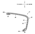
- FIG. 1 Perspective view of the door according to the first embodiment Schematic side view of the door trim according to the first embodiment Section III-III sectional view of FIG.
- Perspective view of the abnormal noise suppressing member according to the first embodiment Side view of the abnormal noise suppressing member according to the first embodiment Sectional drawing which shows the state which the pushing pressure is acting on the door which concerns on 1st Embodiment Sectional drawing which shows the state which the door trim which concerns on 1st Embodiment is not attached to a door panel
- Schematic side view of the door trim according to the second embodiment (A) Side view of the abnormal noise suppressing member according to the second embodiment, (B) Rear view of the abnormal noise suppressing member according to the second embodiment.
- FIG. 1 Schematic diagram illustrating the mounting structure of the abnormal noise suppressing member according to the second embodiment to the trim main body portion.
- Perspective view of the door according to the fifth embodiment Perspective view of the armrest according to the fifth embodiment
- the traveling direction of the vehicle (automobile) provided with the door D and the door trim 1 is “front”
- the backward direction is “rear”
- the vertical direction is “up” and “down”
- the vehicle width direction is “left” and “right”.
- the positional relationship is determined as.
- the inside in the vehicle width direction (left-right direction) is defined as “inside the vehicle”
- the outside in the vehicle width direction (left-right direction) is defined as "outside the vehicle”.
- the door D is arranged along the side surface of the vehicle and is provided so as to be openable and closable. As shown in FIG. 1, the door D includes a door trim 1 (an example of an interior component) and a door panel P (an example of an exterior component).
- the door trim 1 has a trim main body portion 2 (an example of the main body portion) provided inside the vehicle of a metal (for example, iron) door panel P.
- the trim main body portion 2 has a main surface portion 3 facing in the vehicle width direction and an edge portion 4 corresponding to the peripheral edge of the main surface portion 3.
- the edge portion 4 extends from the end portion of the main surface portion 3 toward the outside of the vehicle. Further, the vehicle outer end portion of the edge portion 4 is in contact with the door panel P, and is attached to the door panel P via a fastening member such as a clip.
- the door trim 1 is made of resin.
- the door trim 1 has an armrest 6 having an armrest upper wall 7 that bulges inward from the trim main body 2 and faces up and down, and an armrest side wall 8 that extends downward from the inner end of the armrest upper wall 7. ing.
- the armrest 6 bulges from an intermediate portion in the vertical direction of the main surface portion 3.
- the armrest 6 functions as an armrest for the occupant to place his / her arm.
- the armrest upper wall 7 extends substantially horizontally from the main surface portion 3 to the inside of the vehicle.
- the rear end of the armrest side wall 8 is inclined toward the rear to the outside of the vehicle.
- a switch portion 9 for an occupant to open and close a window is provided on the front portion of the armrest upper wall 7.
- the armrest 6 has a built-in heater 10 composed of a heating wire or the like.
- the door trim 1 has a box shape that opens upward, and has a pull pocket body 13 that defines a pull pocket space 14 that is recessed downward from the armrest upper wall 7.
- the pull pocket body 13 functions as a gripping portion for gripping when the occupant opens and closes the door D.
- the pull pocket body 13 is made of resin.
- a speaker grill 16 is provided at the lower front portion of the trim main body portion 2.
- the speaker grill 16 covers the inside of the vehicle of the speaker 17.
- a protector 18 is arranged on the outside of the vehicle at the lower rear portion of the trim main body 2.
- the protector 18 is made of a synthetic resin material such as polypropylene, and absorbs an impact applied to the door panel P at the time of a side collision of the vehicle.
- a door handle 19 for opening and closing the door D from the inside of the vehicle is installed on the upper part of the trim main body 2. The door handle 19 is not shown in FIG.
- ⁇ Abnormal noise suppression member 21> With reference to FIG. 2, two abnormal noise suppressing members 21 are provided on the upper portion of the back surface 2A (the surface on the outer side of the vehicle) of the trim main body 2 at intervals in the front-rear direction. As will be described later, the two abnormal noise suppressing members 21 have a function of suppressing the generation of abnormal noise due to vibration when the vehicle is running, vibration when the door is opened and closed, and the like. In another embodiment, only one abnormal noise suppressing member 21 may be provided in the trim main body 2, or three or more abnormal noise suppressing members 21 may be provided in the trim main body 2. ..
- each abnormal noise suppressing member 21 will be described with reference to a state in which the door trim 1 is assembled to the door panel P (see FIG. 1).
- each abnormal noise suppressing member 21 is arranged above the speaker grill 16 and the protector 18 and below the door handle 19. That is, each abnormal noise suppressing member 21 is arranged so as to avoid the speaker grill 16, the protector 18, and the door handle 19. It is preferable that each abnormal noise suppressing member 21 is arranged so as to avoid the heater 10 built in the armrest 6.
- One or both abnormal noise suppressing members 21 may be arranged inside the vehicle (rear surface side) of the pull pocket body 13.
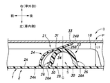
- each abnormal noise suppressing member 21 includes a stopper 23 and an elastic protrusion 24 arranged so as to overlap the stopper 23 from the front side.
- the elastic protrusion 24 may be arranged so as to overlap the stopper 23 from the rear side, the upper side, or the lower side.
- the stopper 23 and the elastic protrusion 24 may be arranged in the front-rear direction or in the up-down direction.
- the stopper 23 of each abnormal noise suppressing member 21 protrudes from the back surface 2A of the trim main body 2 toward the outside of the vehicle and faces the door panel P at a distance.
- the stopper 23 is integrally formed with the trim main body 2 by the same material as the trim main body 2.
- the stopper 23 may be formed of a material different from that of the trim main body 2, or may be formed separately from the trim main body 2.
- the stopper 23 has a substantially semi-cylindrical shape and extends in the vertical direction (an example of the extending direction along the trim main body 2).
- the stopper 23 has a pair of main wall portions 26 extending in the vertical direction (front main wall portion 26 and a rear main wall portion 26) and a lower end portion of the pair of main wall portions 26 extending in the front-rear direction (vertical direction). It is provided with a connection wall portion 28 for connecting the end portion). In another embodiment, the stopper 23 may include only a pair of main wall portions 26.
- the pair of main wall portions 26 of the stopper 23 project from the back surface 2A of the trim main body portion 2 toward the outside of the vehicle.
- Each main wall portion 26 is curved so as to bulge toward the outside of the vehicle, and is inclined toward the outside of the vehicle toward the front-rear center line C side of the stopper 23.
- a recess 30 continuous in the vertical direction is formed on the inner surface of the vehicle inner end portion 26A (corresponding to the vehicle inner end portion of the entire stopper 23) of each main wall portion 26. Therefore, the vehicle inner end portion 26A of each main wall portion 26 is formed to be thinner than the portion other than the vehicle inner end portion 26A of each main wall portion 26.
- each main wall portion 26 (corresponding to the vehicle outer end portion of the entire stopper 23) is connected to each other at a position overlapping the front-rear center line C of the stopper 23.
- a contact surface 31 is provided on the outer surface of the main wall portion 26 on the front side.
- the contact surface 31 has an arc shape that swells toward the outside of the vehicle.
- connection wall portion 28 of the stopper 23 protrudes from the back surface 2A of the trim main body portion 2 toward the outside of the vehicle.
- the connecting wall portion 28 closes the lower end portion of the space S (that is, the internal space of the stopper 23) formed between the pair of main wall portions 26.
- the elastic protrusion 24 of each abnormal noise suppressing member 21 is arranged adjacent to the stopper 23.
- the elastic protrusion 24 projects from the back surface 2A of the trim main body 2 toward the outside of the vehicle.
- the elastic protrusion 24 is inclined to the rear side (stopper 23 side) toward the outside of the vehicle.
- the elastic protrusion 24 is integrally formed with the trim main body 2 by the same material as the trim main body 2. In another embodiment, the elastic protrusion 24 may be formed separately from the trim main body portion 2 or may be formed of a material different from the trim main body portion 2.
- the elastic protrusion 24 has a thin plate shape and extends in the vertical direction (an example of the extending direction along the trim main body 2).
- the width W1 of the elastic protrusion 24 in the vertical direction is narrower than the width W2 of the stopper 23 in the vertical direction.
- the elastic protrusion 24 has a spring property and is provided so as to be elastically deformable.
- the vehicle inner end 24A of the elastic protrusion 24 faces the vehicle inner end 26A of the main wall 26 on the front side of the stopper 23 at a distance in the front-rear direction (direction orthogonal to the vertical direction).
- the vehicle inner end portion 24A of the elastic projection 24 is slightly inclined forward toward the upper side. Therefore, the facing distance X between the vehicle inner end portion 26A of the main wall portion 26 on the front side of the stopper 23 and the vehicle inner end portion 24A of the elastic protrusion 24 is from the lower side (one side in the vertical direction) to the upper side (the other side in the vertical direction). ) Is getting wider and wider.
- a first contact portion 33 is provided on the vehicle outer end portion 24B of the elastic protrusion 24.
- the first contact portion 33 is in contact with the vehicle inner surface of the door panel P and is pressed against the vehicle inner surface of the door panel P.
- the elastic projection 24 is elastically deformed.
- the first contact portion 33 does not contact the stopper 23 and is elastically deformable. That is, the first contact portion 33 has a free end.
- the first contact portion 33 is located on the outer side of the vehicle with respect to the outer end of the protector 18.
- the elastic projection 24 is provided with a second contact portion 34 inside the vehicle rather than the first contact portion 33.
- the second contact portion 34 is a state in which the elastic projection 24 is elastically deformed (see FIG. 3), and the second contact portion 34 is referred to as a contact surface 31 of the main wall portion 26 on the front side of the stopper 23 (hereinafter, “contact surface 31 of the stopper 23”). It is in contact with (referred to as).
- the contact position between the second contact portion 34 and the contact surface 31 of the stopper 23 is larger than the vehicle outer end portion 26B of each main wall portion 26 of the stopper 23 (corresponding to the vehicle outer end portion of the entire stopper 23). It is located inside the car.
- FIG. 3 shows a state in which the pressing force from the inside of the vehicle to the outside of the vehicle does not act on the door D.
- the posture of the elastic protrusion 24 in this state is referred to as a “first posture”.
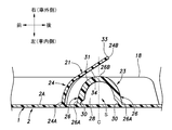
- FIG. 6 shows a state in which a pressing force is applied to the door D from the inside of the vehicle to the outside of the vehicle.
- the posture of the elastic protrusion 24 in this state is referred to as a “second posture”.
- vibration is generated as the vehicle travels, the door D opens and closes, and the like, and when a pressing force acts on the door D from the inside of the vehicle to the outside of the vehicle, the elastic projection 24 first comes into contact with the door D.
- the portion 33 is pressed inside the vehicle by the door panel P.
- the elastic projection 24 is elastically deformed from the first posture to the second posture.
- the portion of the elastic projection 24 that is outside the vehicle from the second contact portion 34 is greatly elastically deformed while maintaining a distance from the contact surface 31 of the stopper 23.
- the length of the elastic protrusion 24 in the vehicle width direction decreases from L1 to L2, and the contact position between the contact surface 31 of the stopper 23 and the second contact portion 34 of the elastic protrusion 24 moves to the outside of the vehicle. (In other words, the second contact portion 34 of the elastic projection 24 moves to the tip end side of the elastic projection 24).
- the elastic protrusion 24 elastically returns from the second posture to the first posture.
- the length of the elastic protrusion 24 in the vehicle width direction increases from L2 to L1
- the contact position between the contact surface 31 of the stopper 23 and the second contact portion 34 of the elastic protrusion 24 moves to the inside of the vehicle. (In other words, the second contact portion 34 of the elastic projection 24 moves to the base end side of the elastic projection 24).
- the elastic projection 24 elastically deforms while maintaining the contact state with the door panel P. As a result, the impact of the pressing force on the door D from the inside of the vehicle to the outside of the vehicle is alleviated, and the generation of abnormal noise is suppressed.
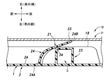
- the door trim 1 configured as described above is arranged so as to face the door panel P.
- the edge portion 4 of the trim main body portion 2 of the door trim 1 is brought into contact with the door panel P, and is attached to the door panel P by a fastening member such as a clip.
- a fastening member such as a clip
- the elastic protrusion 24 is not elastically deformed and faces the stopper 23 at a distance. That is, the second contact portion 34 of the elastic projection 24 does not contact the contact surface 31 of the stopper 23.
- the length of the elastic protrusion 24 and the amount of elastic deformation (deflection amount) become insufficient, and the cushioning action of the elastic protrusion 24 is reduced. There is a risk of doing so.
- the length of the elastic protrusion 24 and the amount of elastic deformation (deflection amount) can be sufficiently secured. Therefore, the buffering action of the elastic protrusion 24 can be enhanced, and the generation of abnormal noise can be effectively suppressed.
- the contact surface 31 of the stopper 23 has an arc shape that swells toward the outside of the vehicle.
- the width W1 of the elastic protrusion 24 in the vertical direction is narrower than the width W2 of the stopper 23 in the vertical direction.
- the vehicle inner end portion 26A of the main wall portion 26 on the front side of the stopper 23 and the vehicle inner end portion 24A of the elastic protrusion 24 face each other with a space in the front-rear direction.
- the elastic protrusion 24 is compared with the case where the car inner end 26A of the main wall 26 on the front side of the stopper 23 and the car inner end 24A of the elastic protrusion 24 are in contact with each other.
- the degree of freedom of elastic deformation can be increased. Therefore, the buffering action of the elastic projection 24 can be further enhanced, and the generation of abnormal noise can be suppressed more effectively.
- the facing distance X between the vehicle inner end portion 26A of the main wall portion 26 on the front side of the stopper 23 and the vehicle inner end portion 24A of the elastic protrusion 24 gradually widens from the lower side to the upper side.
- the stopper 23 includes a pair of main wall portions 26, and the vehicle outer end portions 26B of the pair of main wall portions 26 are connected to each other.
- the elastic projection 24 can be stably supported by the stopper 23 having a simple configuration.
- each main wall portion 26 is formed to be thinner than the portion other than the vehicle inner end portion 26A of each main wall portion 26.
- a recess 30 continuous in the vertical direction is formed on the inner surface of the vehicle inner end portion 26A of each main wall portion 26.
- the stopper 23 further includes a connecting wall portion 28 for connecting the lower end portions of the pair of main wall portions 26.
- the elastic protrusion 24 faces the stopper 23 at a distance.
- the elastic projection 24 is elastically deformed by the door panel P pressing the first contact portion 33, and the second contact portion 34 is attached to the contact surface 31 of the stopper 23. Contact.
- the elastic protrusion 24 can be stably brought into contact with the door panel P and the stopper 23 in a state where the door trim 1 is assembled to the door panel P. Therefore, the buffering action of the elastic projection 24 can be further enhanced, and the generation of abnormal noise can be suppressed more effectively.
- the vehicle inner end portion 24A of the elastic protrusion 24 and the vehicle inner end portion 26A of the main wall portion 26 on the front side of the stopper 23 face each other at a distance.
- the vehicle inner end portion 24A of the elastic projection 24 and the vehicle inner end portion 26A of the main wall portion 26 on the front side of the stopper 23 may be in contact with each other.
- the pair of main wall portions 26 of the stopper 23 are curved so as to bulge toward the outside of the vehicle.
- the main wall portion 26 on the front side of the stopper 23 bulges toward the vehicle outer side.
- the main wall portion 26 on the rear side of the stopper 23 may extend linearly in the vehicle width direction.
- the stopper 23 has a substantially semi-cylindrical shape.
- the stopper 23 may have a square frame shape.
- the shape of the stopper 23 may be any shape as long as the elastic protrusion 24 can be brought into contact with the stopper 23.
- the stopper 23 is hollow, but in other embodiments, the stopper 23 may not be hollow.
- the shape of the elastic protrusion 24 may be any shape as long as the elastic protrusion 24 can be elastically deformed.
- the elastic protrusion 24 has a thin plate shape, but in other embodiments, the elastic protrusion 24 may have a shape other than the thin plate shape (for example, a rod shape).
- two abnormal noise suppressing members 43 are provided on the upper portion of the back surface 2A (the surface on the outer side of the vehicle) of the trim main body 2 at intervals in the front-rear direction. As will be described later, the two abnormal noise suppressing members 43 have a function of suppressing the generation of abnormal noise due to vibration when the vehicle is running, vibration when the door is opened and closed, and the like. In another embodiment, only one abnormal noise suppressing member 43 may be provided in the trim main body portion 2, or three or more abnormal noise suppressing members 43 may be provided in the trim main body portion 2. ..
- each abnormal noise suppressing member 43 is made of a resin material such as polypropylene. Each abnormal noise suppressing member 43 is arranged above the speaker grill 16 and the protector 18 and below the door handle 19. That is, each abnormal noise suppressing member 43 is arranged so as to avoid the speaker grill 16, the protector 18, and the door handle 19. It is preferable that each abnormal noise suppressing member 43 is arranged so as to avoid the heater 10 built in the armrest 6.
- One or both abnormal noise suppressing members 43 may be arranged inside the vehicle (rear surface side) of the pull pocket body 13.
- each abnormal noise suppressing member 43 includes a base portion 44 and a plurality of elastic contact portions 45 supported by the base portion 44.
- each abnormal noise suppressing member 43 protrudes from the back surface 2A of the trim main body portion 2 toward the outside of the vehicle.
- the base portion 44 is formed separately from the back surface 2A of the trim main body portion 2.
- the base portion 44 may be integrally formed with the back surface 2A of the trim main body portion 2.
- the base portion 44 has a cylindrical shape extending in the vehicle width direction.
- the plurality of elastic contact portions 45 of each abnormal noise suppressing member 43 are integrally formed with the base portion 44. In another embodiment, the plurality of elastic contact portions 45 may be formed separately from the base portion 44. The plurality of elastic contact portions 45 are contained within the contour of the base portion 44 when viewed in the vehicle width direction. The plurality of elastic contact portions 45 project from the vehicle outer end portion of the base portion 44 toward the radial inward side of the base portion 44. The plurality of elastic contact portions 45 are arranged at intervals in the circumferential direction of the base portion 44. The plurality of elastic contact portions 45 are arranged radially around the axis 44A of the base portion 44.
- Each elastic contact portion 45 is inclined to the outside of the vehicle toward the tip side (the radial inside of the base portion 44). Therefore, the tip portion 45A of each elastic contact portion 45 is located outside the vehicle from the base end portion 45B and the base portion 44 of each elastic contact portion 45.
- the tip portion 45A of each elastic contact portion 45 is located on the vehicle outer side of the vehicle outer end portion of the protector 18. With the door trim 41 assembled to the door panel P, the tip portion 45A of each elastic contact portion 45 faces the inner surface of the door panel P at a distance.
- the tip portion 45A of each elastic contact portion 45 may be in contact with the vehicle inner surface of the door panel P in a state where the door trim 41 is assembled to the door panel P.
- the width of each elastic contact portion 45 gradually narrows toward the tip end side. Therefore, the width of the tip portion 45A of each elastic contact portion 45 is narrower than the width of the base end portion 45B of each elastic contact portion 45.
- each abnormal noise suppressing member 43 Vibration occurs as the vehicle travels, the door D opens and closes, and when a pressing force acts on the door D from the inside of the vehicle to the outside of the vehicle, the tip 45A of each elastic contact portion 45 hits the door panel P. Each elastic contact portion 45 is elastically deformed in contact with each other. As a result, the impact of the pressing force on the door D from the inside of the vehicle to the outside of the vehicle is alleviated, and the generation of abnormal noise is suppressed.
- each elastic contact portion 45 In a state where the pressing force from the inside of the vehicle to the outside of the vehicle does not act on the door D, the base portion 44 faces the door panel P via a predetermined distance. On the other hand, when each elastic contact portion 45 is elastically deformed by a predetermined amount due to the pressing force acting on the door D from the inside of the vehicle to the outside of the vehicle, the base portion 44 abuts on the door panel P. As a result, the elastic deformation of each elastic contact portion 45 is restricted.
- each abnormal noise suppressing member 43 is attached to the trim main body portion 2.
- each abnormal noise suppressing member 43 is attached to the trim main body portion 2.
- each abnormal noise suppressing member 43 has hinges 57. It is connected via.
- the base portion 44, the trim main body portion 2, and the hinge 57 are integrally formed of the same material (for example, a resin material).
- a fitting protrusion 58 is integrally formed on the base portion 44, and the fitting protrusion 58 is fitted in the fitting hole 59 of the trim main body portion 2.
- each abnormal noise suppressing member 43 is attached to the trim main body portion 2.
- each abnormal noise suppressing member 43 may be formed separately from the trim main body portion 2 (see the first and second examples of the above-mentioned mounting structure), and may be integrated with the trim main body portion 2. It may be formed in (see the third example of the mounting structure described above).
- the vehicle door trim 41 according to the second embodiment is supported by a trim main body 2 provided inside the vehicle of the door panel P, a base 44 protruding from the trim main body 2 toward the outside of the vehicle, and a base 44.
- a plurality of elastic contact portions 45 that abut on the door panel P and elastically deform are provided, and the plurality of elastic contact portions 45 are contained within the contour of the base portion 44 when viewed in the vehicle width direction. As described above, the plurality of elastic contact portions 45 abut on the door panel P and elastically deform, so that the buffering action can be enhanced and the generation of abnormal noise can be effectively suppressed.
- the plurality of elastic contact portions 45 are contained within the contour of the base portion 44 as described above, it is possible to suppress the increase in size of the plurality of elastic contact portions 45. Further, by attaching the resin abnormal noise suppressing member 43 to the trim main body 2, the abnormal noise suppressing member 43 is compared with the case where the abnormal noise suppressing member 43 formed of the non-woven fabric is attached to the trim main body 2. It can be easily attached to the trim main body 2 and the productivity can be improved. Further, by changing the thickness of the plurality of elastic contact portions 45, the cushioning function of each abnormal noise suppressing member 43 can be easily adjusted.
- the base portion 44 has a cylindrical shape, and the plurality of elastic contact portions 45 project from the base portion 44 inward in the radial direction of the base portion 44, and the axial center 44A of the base portion 44 is formed. They are arranged radially around the center.
- each abnormal noise suppressing member 61 includes a base portion 62 and a plurality of elastic contact portions 63 supported by the base portion 62.
- each abnormal noise suppressing member 61 projects from the back surface 2A of the trim main body portion 2 toward the outside of the vehicle.
- the base portion 62 is formed separately from the back surface 2A of the trim main body portion 2.
- the base portion 62 may be integrally formed with the back surface 2A of the trim main body portion 2.
- the base portion 62 has a square cylinder shape extending in the vehicle width direction.
- the base portion 62 has a pair of support wall portions 65 extending in the vertical direction (a front support wall portion 65 and a rear support wall portion 65) and an upper end portion and a lower end portion of the pair of support wall portions 65 extending in the front-rear direction.
- a pair of connecting wall portions 66 (upper connecting wall portion 66 and lower connecting wall portion 66) are provided.
- the base portion 62 may include only a pair of support wall portions 65. That is, the base portion 62 does not necessarily have to be formed in the shape of a square cylinder.
- the pair of support wall portions 65 of the base portion 62 face each other at intervals in the front-rear direction.
- the pair of support wall portions 65 are arranged so as to sandwich each elastic contact portion 63 from both front and rear sides when viewed in the vehicle width direction.
- the pair of support wall portions 65 may be arranged so as to sandwich the elastic contact portions 63 from both the upper and lower sides when viewed in the vehicle width direction.
- the pair of connecting wall portions 66 of the base portion 62 face each other at intervals in the vertical direction.
- the pair of connecting wall portions 66 are arranged so as to sandwich the elastic contact portions 63 from both the upper and lower sides when viewed in the vehicle width direction.
- the pair of connecting wall portions 66 may be arranged so as to sandwich the elastic contact portions 63 from both the front and rear sides when viewed in the vehicle width direction.
- the plurality of elastic contact portions 63 of each abnormal noise suppressing member 61 are integrally formed with the base portion 62. In another embodiment, the plurality of elastic contact portions 63 may be formed separately from the base portion 62. The plurality of elastic contact portions 63 are contained within the contour of the base portion 62 when viewed in the vehicle width direction. The plurality of elastic contact portions 63 are arranged in the vertical direction.
- Each elastic contact portion 63 includes a pair of contact pieces 68.
- Each contact piece 68 extends from the vehicle outer end of each support wall portion 65 of the base portion 62 toward the front-rear center line Y of the base portion 62.
- the tip portion 68A of one contact piece 68 and the tip portion 68A of the other contact piece 68 face each other with a distance in the front-rear direction.
- the vertical width of each contact piece 68 is constant from the base end side to the tip end side. Therefore, the vertical width of the tip end portion 68A of each contact piece 68 is equal to the vertical width of the base end portion 68B of each contact piece 68.
- Each contact piece 68 is inclined to the outside of the vehicle toward the tip side (Y side of the front-rear center line of the base portion 62). Therefore, the tip end portion 68A of each contact piece 68 is located outside the vehicle from the base end portion 68B and the base portion 62 of each contact piece 68. The tip end portion 68A of each contact piece 68 is located outside the vehicle side of the vehicle side end portion of the protector 18. With the door trim 41 assembled to the door panel P, the tip 68A of each contact piece 68 faces the inner surface of the door panel P at a distance. In another embodiment, the tip end portion 68A of each contact piece 68 may be in contact with the vehicle inner surface of the door panel P in a state where the door trim 41 is assembled to the door panel P.
- the degree of inclination of each contact piece 68 toward the outside of the vehicle is different for each elastic contact portion 63.
- the degree of inclination of each contact piece 68 toward the outside of the vehicle is the largest in the elastic contact portion 63 at the center in the vertical direction and the smallest in the elastic contact portions 63 at both ends in the vertical direction.
- the vehicle door trim 41 according to the third embodiment is supported by a trim main body 2 provided inside the vehicle of the door panel P, a base portion 62 protruding from the trim main body 2 toward the outside of the vehicle, and a base portion 62.
- a plurality of elastic contact portions 63 that abut on the door panel P and elastically deform are provided, and the plurality of elastic contact portions 63 are contained within the contour of the base portion 62 when viewed in the vehicle width direction.
- the plurality of elastic contact portions 63 abut on the door panel P and elastically deform, so that the buffering action can be enhanced and the generation of abnormal noise can be effectively suppressed.
- the plurality of elastic contact portions 63 are contained within the contour of the base portion 62 as described above, it is possible to suppress the increase in size of the plurality of elastic contact portions 63.
- the base portion 62 includes a pair of support wall portions 65 extending in the vertical direction (first direction orthogonal to the vehicle width direction), and the plurality of elastic contact portions 63 are formed from the support wall portions 65 to the base portion. It is provided with a pair of contact pieces 68 extending toward the front-rear center line Y (center line in the vehicle width direction and the second direction orthogonal to the first direction) of 62.
- each abnormal noise suppressing member 71 includes a base portion 72 and an elastic contact portion 73 supported by the base portion 72.
- each abnormal noise suppressing member 71 protrudes from the back surface 2A of the trim main body portion 2 toward the outside of the vehicle.
- the base portion 72 is formed separately from the back surface 2A of the trim main body portion 2.
- the base portion 72 may be integrally formed with the back surface 2A of the trim main body portion 2.
- the base portion 72 has a cylindrical shape extending in the vehicle width direction.
- each abnormal noise suppressing member 71 is integrally formed with the base portion 72.
- the elastic contact portion 73 may be formed separately from the base portion 72.
- the elastic contact portion 73 is within the contour of the base portion 72 when viewed in the vehicle width direction.
- the elastic contact portion 73 includes an elastic piece 75 arranged radially inside the base portion 72 at a distance from the base portion 72, and a pair of connecting pieces 76 connecting the base portion 72 and the elastic piece 75. ing. In another embodiment, the elastic contact portion 73 may include only one connecting piece 76, or the elastic contact portion 73 may include three or more connecting pieces 76. Further, in still another embodiment, the elastic contact portion 73 does not include the connecting piece 76, and the base portion 72 and the elastic piece 75 may be directly connected to each other.
- the elastic piece 75 of the elastic contact portion 73 has a spiral shape centered on the axial center 72A of the base portion 72 when viewed in the vehicle width direction.
- the elastic piece 75 is inclined to the outside of the vehicle toward the tip end side (the radial inside of the base portion 72). Therefore, the tip portion 75A of the elastic piece 75 is located outside the vehicle from the base end portion 75B of the elastic piece 75, each connecting piece 76, and the base portion 72.
- the tip portion 75A of the elastic piece 75 is located outside the vehicle side of the vehicle side end portion of the protector 18. With the door trim 41 assembled to the door panel P, the tip portion 75A of the elastic piece 75 faces the inner surface of the door panel P at a distance.
- the tip of the elastic piece 75 may be in contact with the inner surface of the door panel P in a state where the door trim 41 is assembled to the door panel P.
- the pair of connecting pieces 76 of the elastic contact portion 73 are arranged on opposite sides of the axial center 72A of the base portion 72. Each connecting piece 76 extends along the radial direction of the base portion 72. Each connecting piece 76 connects the outer end portion of the base portion 72 to the base end portion 75B of the elastic piece 75.
- the vehicle door trim 41 according to the fourth embodiment is supported by a trim main body 2 provided inside the vehicle of the door panel P, a base portion 72 protruding from the trim main body 2 toward the outside of the vehicle, and a base portion 72.
- the elastic contact portion 73 is provided with an elastic contact portion 73 that abuts on the door panel P and elastically deforms, and the elastic contact portion 73 is contained within the contour of the base portion 72 when viewed in the vehicle width direction. As described above, the elastic contact portion 73 abuts on the door panel P and elastically deforms, so that the buffering action can be enhanced and the generation of abnormal noise can be effectively suppressed. Further, since the elastic contact portion 73 is contained within the contour of the base portion 72 as described above, it is possible to suppress the increase in size of the elastic contact portion 73.
- the base portion 72 has a cylindrical shape
- the elastic contact portion 73 includes an elastic piece 75 arranged radially inside the base portion 72, and the elastic piece 75 is viewed in the vehicle width direction.
- the base portion 72 has a spiral shape centered on the axis 72A.
- the door trim 1 is an example of an interior part
- the door panel P is an example of an exterior part
- the parts other than the door trim 1 may be used as an example of the interior parts
- the parts other than the door panel P may be used as an example of the exterior parts. That is, the present invention can be widely applied not only to the door D but also to a place other than the door D on the side of the vehicle body (for example, a support such as a B pillar).
- the armrest 81 bulges from an intermediate portion in the vertical direction of the main surface portion 3 of the trim main body portion 2.
- the arm rest 81 functions as an armrest for the occupant to place his / her arm.
- the armrest 81 extends in the front-rear direction.
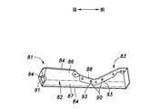
- the armrest 81 includes a resin base material 82, a skin 83 that covers the surface of the base material 82 (the inner surface of the vehicle), and a pair of hooks 84 (upper side) that are attached to the skin 83.
- the hook 84 and the lower hook 84) are provided.
- the armrest 81 may be provided with only one hook 84, or the armrest 81 may be provided with three or more hooks 84.
- the base material 82 of the armrest 81 has a long shape in the front-rear direction.
- the base material 82 includes an upper wall portion 86 extending in the vehicle width direction and a side wall portion 87 extending downward from the vehicle inner end portion of the upper wall portion 86.
- a recess 88 is formed in the front portion of the upper wall portion 86. Therefore, the left-right width of the front portion of the upper wall portion 86 is narrower than the left-right width of the rear portion of the upper wall portion 86.
- a plurality of engaging protrusions 90 are arranged in the front-rear direction on the back surface (lower surface) of the front portion of the upper wall portion 86.
- a pair of bosses 91 project from the back surfaces (outside surfaces of the vehicle) of both front and rear ends of the side wall portion 87.
- the skin 83 of the armrest 81 has a long shape in the front-rear direction and covers the surface of the base material 82.
- a plurality of engaging holes 93 are arranged in the front-rear direction in the front portion of the skin 83.
- the plurality of engaging holes 93 are engaged with the plurality of engaging protrusions 90 of the upper wall portion 86 of the base material 82.
- the front and rear ends of the skin 83 are folded back at the front and rear ends of the base material 82 to reach the back surface of the base material 82.
- a pair of mounting holes 94 are provided at both front and rear ends of the skin 83.
- the pair of mounting holes 94 are engaged with the pair of bosses 91 of the side wall portion 87 of the base material 82.
- the pair of hooks 84 of the armrest 81 are J-shaped.
- the pair of hooks 84 are attached to both sides of the skin 83 in the width direction.
- the upper hook 84 is engaged with the vehicle outer edge portion 86A at the rear portion of the upper wall portion 86 of the base material 82.
- the lower hook 84 is engaged with the lower edge portion 87A of the side wall portion 87 of the base material 82.
- the upper hook 84 is engaged with the vehicle outer edge portion 86A at the rear of the upper wall portion 86 of the base material 82, and the lower hook 84 is engaged with the lower edge portion 87A of the side wall portion 87 of the base material 82. Match. This completes the attachment of the skin 83 to the base material 82.
- the armrest 81 includes a base material 82, a skin 83 that covers the surface of the base material 82, and at least one hook 84 (engagement member) attached to the skin 83, and the hook 84. Is engaged with the base material 82, so that the skin 83 is attached to the base material 82.
- the skin 83 can be attached to the base material 82 without using an adhesive. Therefore, the man-hours for attaching the skin 83 to the base material 82 can be reduced, and the burden on the environment can be reduced. Further, since complicated bonding work is not required, the work of attaching the skin 83 to the base material 82 can be simplified, and the work of the product (that is, the armrest 81) can be suppressed from being varied. ..
- the skin 83 is attached to the base material 82 by engaging the pair of hooks 84 attached to the skin 83 with the pair of edges of the base material 82.
- the skin 83 can be attached to the base material 82 without any special processing on the base material 82.
- the skin 83 is attached to the base material 82 by engaging the pair of hooks 84 attached to the skin 83 with the pair of edges of the base material 82.
- the skin 83 may be attached to the base material 82 by the hook-and-loop fastener 96 provided in the overlapping portion of the base material 82 and the skin 83.
- a pair of hooks 84 attached to the skin 83 engages with a pair of through holes 97 provided in the base material 82 to form the base material 82.
- the skin 83 may be attached.
- a pair of fitting pieces 98 attached to the skin 83 is partially formed in the pair of fitting grooves 99 provided on the back surface of the base material 82.
- the skin 83 may be attached to the base material 82 by fitting together with the base material 82.
- the door trim 101 (an example of an interior component) according to the sixth embodiment has a trim main body 102 (an example of the main body) provided inside the vehicle of the door panel P (an example of an exterior component). ing.
- the trim main body portion 102 has a main surface portion 103 facing in the vehicle width direction and an edge portion 104 corresponding to the peripheral edge of the main surface portion 103.
- the edge portion 104 extends from the end portion of the main surface portion 103 toward the outside of the vehicle. Further, the outer end portion of the edge portion 104 is in contact with the door panel P, and is attached to the door panel P via a fastening member such as a clip.
- the door trim 101 is made of resin.
- the door trim 101 has an armrest 106 having an armrest upper wall 107 that bulges inward from the trim body 102 and faces up and down, and an armrest side wall 108 that extends downward from the inner end of the armrest upper wall 107. ing.
- the armrest 106 bulges from an intermediate portion in the vertical direction of the main surface portion 103.
- the armrest 106 functions as an armrest for the occupant to place his / her arm.
- the armrest upper wall 107 extends substantially horizontally from the main surface portion 103 to the inside of the vehicle.
- the rear end of the armrest side wall 108 is inclined toward the rear to the outside of the vehicle.
- a switch portion 109 is provided on the front portion of the armrest upper wall 107 for the occupant to open and close the window.
- a pull pocket mounting hole 110 and a plurality of fastening holes 112 are formed in the rear portion of the armrest upper wall 107.
- the pull pocket mounting hole 110 penetrates the armrest upper wall 107 up and down.
- the door trim 101 has a box shape that opens upward, and has a pull pocket body 113 that defines a pull pocket space 114 that is recessed downward from the armrest upper wall 107.
- the pull pocket body 113 is arranged in the pull pocket mounting hole 110.
- the pull pocket body 113 functions as a gripping portion for gripping when the occupant opens and closes the door D.
- the pull pocket body 113 is made of resin.
- the pull pocket body 113 has a pocket portion 115 and a flange portion 122.
- the pocket portion 115 of the pull pocket body 113 includes a pocket bottom wall 116 whose surface faces in the vertical direction, and a pocket inner wall 117 whose surface extends upward from the vehicle inner end of the pocket bottom wall 116 and whose surface faces in the vehicle width direction.
- a pocket outer wall 118 that extends upward from the vehicle outer end of the pocket bottom wall 116 and whose surface faces in the vehicle width direction, and a pocket that extends upward from the front end of the pocket bottom wall 116 and whose surface faces in the front-rear direction. It has a front wall 119 and a pocket rear wall 120 that extends upward from the rear end of the pocket bottom wall 116 and whose surface faces in the front-rear direction.
- a plurality of fastening pieces 125 are provided on the pocket bottom wall 116.
- the fastening piece 125 extends downward from the lower surface of the pocket bottom wall 116.
- the fastening piece 125 has an insertion hole for inserting a fastening member such as a bolt, and is fastened to the armrest 106 by the fastening member.
- An overhang portion 124 that bulges toward the outside of the vehicle is formed on the upper part of the inner wall wall 117 of the pocket.
- the overhang portion 124 functions as a hooking portion for the occupant to hook his / her finger on the inner wall wall 117 of the pocket.
- the lower part of the overhang portion 124 is inclined downward toward the inside of the vehicle.
- the inner surface of the pocket inner wall 117 faces the outer surface of the armrest side wall 108 in the vehicle width direction.
- the flange portion 122 of the pull pocket body 113 extends from the upper end portion of the pocket portion 115 in the direction opposite to the pull pocket space 114 in the vehicle width direction.
- the flange portion 122 is arranged at the peripheral edge portion of the pull pocket mounting hole 110 on the upper surface of the armrest upper wall 107.
- a plurality of locking claws 126 extending downward are formed on the lower surface of the flange portion 122.
- the flange portion 122 is coupled to the armrest upper wall 107 by hooking each locking claw 126 to the fastening hole 112.
- a cover member may be provided to cover the flange portion 122 in order to enhance aesthetics and functionality.
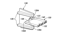
- One of the armrest side wall 108 and the pocket inner wall 117 has at least one protrusion 130 protruding toward the other of the armrest side wall 108 and the pocket inner wall 117. Further, the other side of the armrest side wall 108 and the pocket inner wall 117 has a receiving portion 136 having at least one receiving surface 137 abutting on or close to the protrusion 130 in the vehicle width direction.
- the protrusion 130 is provided on the inner wall wall 117 of the pocket, and the receiving portion 136 is provided on the side wall 108 of the armrest.
- the protrusion 130 is formed in a plate shape and extends in a direction orthogonal to the vehicle width direction.
- the receiving portion 136 is formed in a plate shape and extends in a direction orthogonal to the protrusion 130.
- the protrusion 130 projects from the pocket inner wall 117 toward the inside of the vehicle.
- the protrusion 130 has a protrusion base 131 and a protrusion tip 132.
- the protrusion 130 may be flexible.
- the protrusion 130 is integrally formed with the pull pocket body 113.
- the protrusion base 131 protrudes from the inner wall wall 117 of the pocket toward the inside of the vehicle.
- the protrusion base 131 is formed in a substantially box shape.
- the end surface 131A on the inside of the vehicle of the protrusion base 131 is parallel to the pocket inner wall 117.
- the protrusion tip 132 protrudes toward the inside of the vehicle from the end surface 131A inside the vehicle of the protrusion base 131.
- the protrusion tip 132 is formed in a plate shape extending in the vehicle width direction and the front-rear direction.
- the length of the protrusion tip portion 132 in the front-rear direction is shorter than the length of the protrusion base portion 131 in the front-rear direction.
- the vertical length of the protrusion tip 132 is shorter than the vertical length of the protrusion base 131.
- the protrusion tip 132 may be provided approximately in the center of the end surface 131A inside the vehicle of the protrusion base 131.
- the tip 132A of the protrusion tip 132 may be chamfered.
- the receiving portion 136 projects from the armrest side wall 108 toward the outside of the vehicle and faces the protrusion 130 in the vehicle width direction.
- the receiving portion 136 is formed in a plate shape and extends in the vehicle width direction and the vertical direction. The vertical width of the receiving portion 136 gradually decreases toward the outside of the vehicle.
- the receiving portion 136 is integrally formed with the armrest side wall 108.
- the receiving portion 136 has a receiving surface 137 inclined with respect to the vehicle width direction.
- the receiving surface 137 is provided at a position in contact with or close to the protrusion tip 132 in the vehicle width direction.
- the receiving surface 137 may be in contact with the protrusion tip 132.
- the receiving surface 137 may be provided at the center of the receiving portion 136 on the inner side of the vehicle in the vertical direction of the tip edge 136A.
- the receiving portion 136 has a groove portion 140 at its tip edge 136A.
- the groove 140 is recessed toward the armrest side wall 108, that is, toward the inside of the vehicle.
- the groove portion 140 extends in the front-rear direction and penetrates the receiving portion 136 in the front-rear direction.
- the receiving surface 137 is formed in the groove 140. Specifically, the receiving surface 137 forms part of the wall surface that defines the groove 140.
- the bottom of the groove 140 is provided with a bottom surface 138 facing the vehicle width direction.
- the bottom surface 138 is smoothly connected to the receiving surface 137.
- the groove portion 140 has an arc-shaped cross section. It is preferable that the receiving surface 137 and the bottom surface 138 extend in an arc shape and are connected to each other.
- the receiving portion 136 may have at least one reinforcing member 139. Thereby, the rigidity of the receiving portion 136 can be improved.
- the reinforcing member 139 may be a rib connecting the receiving portion 136 and the armrest side wall 108.
- the reinforcing member 139 may be formed in a plate shape orthogonal to the receiving portion 136.
- the pull pocket body 113 is gripped by an occupant when the door D is opened and closed.
- the occupant hooks his finger on the inner wall wall 117 of the pocket and pulls it inside the vehicle.
- the inner wall wall 117 of the pocket receives a load from the occupant and elastically deforms inside the vehicle.
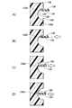
- the protrusion tip 132 when no load is applied to the pocket inner wall 117 from the occupant, the protrusion tip 132 is arranged at a position abutting or in close proximity to the receiving surface 137. .. As shown in FIG. 26B, even if the relative position between the protrusion tip 132 and the receiving surface 137 changes due to a manufacturing error, the protrusion tip 132 is deformed and the protrusion tip 132 hits the receiving surface 137. It is good to be in contact. Further, as shown in FIG. 26 (A), the protrusion tip 132 may be separated from the receiving surface 137 to the outside of the vehicle. At this time, the tip 132A of the protrusion tip 132 may be located in the groove 140.
- the pocket inner wall 117 is moved inside the vehicle.
- the tip portion 132 of the protrusion moves to the inside of the vehicle and comes into contact with the receiving surface 137 (see FIG. 26 (B)).
- the protrusion tip 132 slides on the receiving surface 137 and moves toward the bottom surface 138 (see FIG. 26 (C)).
- the tip 132A of the protrusion tip 132 reaches the bottom surface 138 (see FIG. 26 (D)).
- the bottom surface 138 is a surface facing the vehicle width direction, when the protrusion tip 132 reaches the bottom surface 138, the movement of the protrusion tip 132 toward the inside of the vehicle is restricted by the bottom surface 138. As a result, the pocket inner wall 117 is supported by the armrest side wall 108 via the protrusion 130 and the receiving portion 136, and the deformation of the pocket inner wall 117 to the inside of the vehicle is suppressed. When the occupant stops pulling the pocket inner wall 117, the pocket inner wall 117 is restored by the elastic force, and the protrusion tip 132 returns to the initial position shown in FIG. 26 (A) or FIG. 26 (B).
- the receiving surface 137 corresponding to the protrusion tip 132 is inclined with respect to the vehicle width direction, it is easy to maintain the state in which the protrusion tip 132 and the receiving surface 137 are in contact with each other even when a manufacturing error occurs. As a result, when the pull pocket body 113 is deformed, the collision between the protrusion 130 and the receiving surface 137 is avoided, and the generation of abnormal noise is suppressed.
- the receiving surface 137 is inclined with respect to the vehicle width direction, so that when the protrusion tip 132 abuts on the receiving surface 137, the protrusion tip The 132 is guided in the direction along the receiving surface 137, and the momentum of the collision between the protrusion tip 132 and the receiving surface 137 is reduced. As a result, the generation of abnormal noise is suppressed.
- the protrusion 130 has a simple structure and can be integrally molded with the pull pocket body 113. Further, the receiving portion 136 has a simple structure and can be integrally molded with the armrest 106 and the trim main body portion 102. As a result, the manufacturing cost of the door trim 101 can be reduced.
- the protrusion tip portion 132 and the receiving surface 137 are arranged orthogonally, and the protrusion tip portion 132 stably abuts and slides on the receiving surface 137. Can move.
- the protrusion tip 132 slides on the receiving surface 137, the protrusion 130 bends, so that the load applied to the receiving surface 137 by the protrusion 130 is reduced, and the generation of abnormal noise is further suppressed.
- the tip 132A of the protrusion tip 132 is chamfered, the friction with the receiving surface 137 is reduced. As a result, it is possible to reduce the generation of frictional noise and the wear of the protrusion tip 132 and the receiving surface 137. Further, since the receiving surface 137 is formed in the groove portion 140 and the protrusion tip portion 132 plunges into the groove portion 140, the movement of the protrusion tip portion 132 is restricted by the groove portion 140.
- the receiving surface 137 has an arcuate cross section, the reaction force generated when the protrusion 130 is pressed smoothly increases as the protrusion tip 132 slides on the receiving surface 137. do. As a result, when the protrusion 130 comes into contact with the bottom surface 138, abnormal noise is less likely to occur.
- the groove 140 has an arcuate cross section, but in other embodiments, the groove 140 has a V-shaped (triangular) cross section as shown in FIG. 27. May be.
- the protrusion 130 may be provided on the armrest side wall 108, and the receiving portion 136 may be provided on the pocket inner wall 117.
- one of the armrest side wall 108 and the pocket inner wall 117 has a plurality of protrusions 130, and the other of the armrest side wall 108 and the pocket inner wall 117 has a vehicle width direction with respect to each of the protrusions 130.
- Each of the protrusions 130 may be provided with a connecting portion 133 for connecting to each other.
- the two protrusions 130 are each formed in a plate shape and face each other in parallel.
- the connecting portion 133 connects the side portions of the two protrusions 130 that correspond to each other.
- the connecting portion 133 may extend in the vehicle width direction along the protrusion 130. When viewed from the vehicle width direction, the two protrusions 130 and the connecting portion 133 are arranged in a U shape.
- the connecting portion 133 is arranged at a position where it does not abut on the receiving portion 136 when the protrusion tip portion 132 is in contact with the receiving surface 137.
- the connecting portion 133 improves the rigidity of the protrusion 130.
- the two protrusions 130 have a surface facing in the vertical direction and are arranged vertically apart from each other.
- the connecting portion 133 extends in the vertical direction to connect the two protrusions 130.
- the two receiving portions 136 facing the two protrusions 130 are each formed in a plate shape, and the surfaces thereof face in the front-rear direction.
- the two receiving portions 136 are arranged side by side in the vertical direction and are connected to each other.
- Each receiving portion 136 has a groove portion 140 on the tip edge 136A on the outer side of the vehicle.
- the groove portion 140 has the same configuration as the groove portion 140 according to the sixth embodiment.
- the two groove portions 140 have an arcuate cross-sectional shape when viewed from the front-rear direction.
- a receiving surface 137 is formed in each of the groove portions 140.
- the inclination direction of the receiving surface 137 with which each protrusion 130 abuts may be different.
- the upper receiving surface 137 with which the upper protrusion 130 abuts is inclined upward toward the inside of the vehicle.
- the lower receiving surface 137 with which the lower protrusion 130 abuts is inclined downward toward the inside of the vehicle.
- the upper receiving surface 137 may be arranged in the lower part of the upper groove portion 140, and the lower receiving surface 137 may be arranged in the upper part of the lower groove portion 140. According to this configuration, when each protrusion 130 moves to the inside of the vehicle, the upper protrusion 130 is guided upward to the upper receiving surface 137, and the lower protrusion 130 is guided downward to the lower receiving surface 137. Will be done.
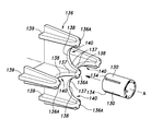
- one of the armrest side wall 108 and the pocket inner wall 117 has a plurality of protrusions 130, and the other of the armrest side wall 108 and the pocket inner wall 117 has a vehicle with respect to each of the protrusions 130. It has one or more receiving portions 136 at positions facing each other in the width direction. Further, each of the protrusions 130 is arranged in the circumferential direction about the center line A. Each of the protrusions 130 is formed in an arc shape centered on the center line A, and a slit 134 is formed between the adjacent protrusions 130.
- each protrusion 130 is arranged side by side in the circumferential direction around the center line A extending in the vehicle width direction on the pocket inner wall 117.
- Each protrusion 130 extends from the inner wall wall 117 of the pocket to the inside of the vehicle.
- each protrusion 130 is formed in an arc shape centered on the center line A when viewed from the vehicle width direction.
- the bases of the protrusions 130 may be connected to each other by a connecting portion 133 extending in the circumferential direction about the center line A.
- These protrusions 130 are formed by providing a plurality of slits 134 in the tubular body 135 centered on the center line A.
- the four receiving portions 136 corresponding to the four protrusions 130 are each formed in a plate shape and extend in the radial direction about the center line A. Further, the four receiving portions 136 are orthogonal to the corresponding protrusions 130 when viewed from the vehicle width direction.
- the four receiving portions 136 are connected to each other at positions overlapping with the center line A, and are formed in a + shape (cross) when viewed from the vehicle width direction.
- a groove 140 is formed at the tip edge 136A on the outer side of the vehicle of each receiving portion 136.
- a receiving surface 137 is formed on the wall surface of each groove 140. The receiving surfaces 137 have different inclination directions from each other.
- the receiving surface 137 of the receiving portion 136 arranged on the upper side of the center line A is inclined upward toward the inside of the vehicle, and the receiving surface 137 of the receiving portion 136 arranged on the front side of the center line A is forward toward the inside of the vehicle.
- the receiving surface 137 of the receiving portion 136 arranged on the lower side of the center line A is inclined downward toward the inside of the vehicle, and the receiving surface 137 of the receiving portion 136 arranged on the rear side of the center line A is inclined to It is tilted backward toward the inside of the car.
- the side protrusion 130 is guided downward to the lower receiving surface 137, and the rear protrusion 130 is guided rearward to the rear receiving surface 137. Since the directions in which the four protrusions 130 are guided are opposite to each other on a plane orthogonal to the vehicle width direction in this way, it is difficult for the pull pocket body 113 to move in the direction orthogonal to the vehicle width direction due to the load received from the receiving portion 136. Become.
- the plurality of protrusions 130 are defined by providing the tubular body 135 with the plurality of slits 134, the plurality of protrusions 130 and the receiving portion 136 can be arranged efficiently in space.
- the vehicle door D according to the ninth embodiment has a first member and a second member facing each other in the vehicle width direction, and one of the first member and the second member is a first member and a second member.
- the other of the first member and the second member has at least one receiving portion 136 having a receiving surface 137 that abuts or is close to the protrusion 130 in the vehicle width direction.
- the receiving surface 137 is inclined with respect to the vehicle width direction.
- the combination of the first member and the second member may be, for example, the door panel P and the door trim 101, the first portion of the door trim 101 and the second portion of the door trim 101, and the like.
- the first portion of the door trim 101 may be, for example, the pull pocket body 113 and the second portion may be the armrest 106.
- the combination of the first member and the second member includes the main surface portion 103 of the door panel P and the door trim 101, the armrest 106 of the door panel P and the door trim 101, the pull pocket body 113 of the door panel P and the door trim 101, and the like.
- FIG. 31 shows an example in which the first member is a metal door panel P and the second member is a resin door trim 101 coupled to the door panel P.
- a protrusion 130 is provided on the door panel P, and a receiving portion 136 is provided on the door trim 101.
- the configuration of the protrusion 130 and the receiving portion 136 the configuration of the protrusion 130 and the receiving portion 136 according to the sixth to eighth embodiments may be incorporated.
- the protrusion 130 and the receiving portion 136 may be formed of resin.
- the protrusion 130 is formed in a plate shape and extends in a direction orthogonal to the vehicle width direction.
- the receiving portion 136 is formed in a plate shape and extends in a direction orthogonal to the protrusion 130.
- the protrusion 130 may be formed of resin and may be bonded to the inner surface of the door panel P by a fastening member such as a clip or a screw or an adhesive.
- the protrusion base 131 projects from the door panel P toward the inside of the vehicle.
- the protrusion base 131 is formed in a substantially box shape.
- the end surface 131A on the inside of the vehicle of the protrusion base 131 is parallel to the door trim 101.
- the receiving portion 136 projects from the door trim 101 toward the outside of the vehicle and faces the protrusion 130 in the vehicle width direction.
- the receiving portion 136 is formed in a plate shape and extends in the vehicle width direction and the vertical direction.
- the receiving portion 136 may be formed of resin and integrally formed on the side surface of the door trim 101 on the outer side of the vehicle.
- One aspect of the present invention is a vehicle door (D), which has a first member and a second member facing each other in the vehicle width direction, and one of the first member and the second member is the first member. It has at least one protrusion (130) protruding toward the other of the one member and the second member, and the other of the first member and the second member abuts or approaches the protrusion in the vehicle width direction. It has at least one receiving portion (136) having a receiving surface (137), and the receiving surface is inclined with respect to the vehicle width direction. According to this aspect, it is possible to suppress the generation of collision noise between members in a vehicle door.
- the protrusions are likely to be maintained in contact with the receiving surface by sliding on the receiving surface.
- the receiving surface is inclined with respect to the vehicle width direction, so that when the protrusion collides with the receiving surface, the protrusion follows the receiving surface. It is guided in the direction and the generation of collision noise is suppressed.
- the first member is a metal door panel (P)
- the second member is a resin door trim (101) coupled to the door panel. According to this configuration, it is possible to suppress the generation of collision noise between the door panel and the door trim in the vehicle door.
- a door trim which is a trim main body portion (102) provided inside the vehicle of a door panel, and an armrest upper wall (107) that bulges inward from the trim main body portion and faces up and down.
- an armrest (106) having an armrest side wall (108) extending downward from the inner end of the armrest upper wall, and a pull pocket space recessed downward from the armrest upper wall having a box shape opened upward. It has a pull pocket body (113) defining 114), and the pull pocket body has a pocket inner wall (117) facing the armrest side wall in the vehicle width direction, and the armrest side wall and the pocket inner wall.
- One has at least one protrusion that projects toward the other of the armrest side wall and the pocket inner wall, and the other of the armrest side wall and the pocket inner wall abuts or is close to the protrusion in the vehicle width direction. It has at least one receiving portion having a surface, and the receiving surface is inclined with respect to the vehicle width direction. According to this aspect, it is possible to suppress the generation of collision noise between the pull pocket body and the armrest in the door trim. Even if the relative position between the protrusion and the receiving portion changes due to a manufacturing error, the protrusion can be easily maintained in contact with the receiving surface by sliding on the receiving surface.
- the receiving surface is inclined with respect to the vehicle width direction, so that when the protrusion collides with the receiving surface, the protrusion follows the receiving surface. It is guided in the direction and the generation of collision noise is suppressed.
- the protrusion is formed in a plate shape and extends in a direction orthogonal to the vehicle width direction
- the receiving portion is formed in a plate shape and extends in a direction orthogonal to the protrusion. It is good. According to this configuration, the protrusions and the receiving surface are arranged orthogonally to each other, so that the protrusions can be reliably in contact with the receiving surface.
- the receiving portion has a groove portion (140) at the tip edge (136A) thereof, and the receiving surface is formed in the groove portion. According to this configuration, since the receiving surface is formed in the groove portion and the protrusion penetrates into the groove portion, the movement of the protrusion is restricted by the groove portion.
- the groove portion may have an arc-shaped cross section. According to this configuration, as the protrusion slides on the receiving surface, the reaction force generated when the protrusion is pressed is smoothly increased from the receiving surface. Therefore, when the protrusion abuts on the bottom surface, collision noise is less likely to occur.
- a plurality of the protrusions are provided and a plurality of the receiving portions are provided. According to this configuration, the load applied by one protrusion to one receiving portion is reduced, and the generation of collision noise is suppressed.
- the two adjacent protrusions are connected to each other by the connecting portion (133). According to this configuration, the rigidity of the protrusion can be improved.
- each of the protrusions is arranged in the circumferential direction centered on the predetermined center line (A) when viewed from the vehicle width direction. According to this configuration, the protrusions can be closely arranged to save space.
- each of the protrusions is formed in an arc shape centered on the center line, and a slit (134) is formed between the two adjacent protrusions. According to this configuration, a plurality of protrusions and receiving portions can be arranged in a space-efficient manner.
- the protrusion has flexibility. According to this configuration, the bending of the protrusion reduces the load applied to the receiving surface by the protrusion and suppresses the generation of collision noise.
- the tip (132A) of the protrusion is chamfered. According to this configuration, the friction generated when the protrusion slides on the receiving surface is reduced, and the generation of frictional noise and the wear of the protrusion and the receiving surface can be reduced.
- the receiving portion has at least one reinforcing member (139). According to this configuration, the rigidity of the receiving portion can be improved.
- the present invention can be widely modified without being limited to the above embodiment.
- the shapes and numbers of the protrusions 130 and the receiving portions 136 may be appropriately changed.
- the groove portion 140 is not an essential configuration and may be omitted.
- the receiving surface 137 may be formed in the entire area of the tip edge 136A of the receiving portion 136.
- the door trim 101 is an example of an interior part
- the door panel P is an example of an exterior part
- the parts other than the door trim 101 may be used as an example of the interior parts
- the parts other than the door panel P may be used as an example of the exterior parts. That is, the present invention can be widely applied not only to the door D but also to a place other than the door D on the side of the vehicle body (for example, a support such as a B pillar).
Abstract
[Problem] To provide a door trim capable of suppressing noise. [Solution] A door trim 1 for a vehicle comprises a main trim part 2 provided on the interior side of a door panel P, and a stopper 23 and an elastic protrusion 24 that project toward the vehicle exterior from the main trim part 2, wherein the stopper 23 faces the door panel P with a space in between, and the elastic protrusion 24 includes a first abutting part 33 that abuts against the door panel P and a second abutting part 34 which is disposed farther on the interior side than the first abutting part 33 and which abuts against the stopper 23.
Description
本発明は、車両用のドアトリム及び車両用の内装部品に関する。
The present invention relates to a door trim for a vehicle and an interior component for a vehicle.
従来、車両用のドアの車内側の面には、ドアトリム(内装部品)が設けられている。
Conventionally, a door trim (interior part) is provided on the inner surface of the vehicle door.
例えば、特許文献1には、ドアインナパネルに当接するトリム保持手段を備えたドアトリムが開示されている。上記のトリム保持手段は、ドアトリムの背面に一体に突設した座部と、この座部の先端に一体成形された撓み変形可能なばね部と、を備えている。
For example, Patent Document 1 discloses a door trim provided with a trim holding means that abuts on the door inner panel. The trim holding means includes a seat portion integrally projecting from the back surface of the door trim, and a flexibly deformable spring portion integrally molded at the tip of the seat portion.
上記のトリム保持手段は、ばね部の撓み変形量が所定量を超えると、ばね部が座部に突き当たるように構成されている(特許文献1の図4参照)。このような構成を採用すると、ばね部が座部に突き当たる際に、異音が発生する虞がある。
The trim holding means is configured such that when the amount of bending deformation of the spring portion exceeds a predetermined amount, the spring portion abuts on the seat portion (see FIG. 4 of Patent Document 1). If such a configuration is adopted, abnormal noise may be generated when the spring portion abuts on the seat portion.
本発明は、以上の背景に鑑み、異音の発生を抑制することが可能なドアトリムを提供することを課題とする。
In view of the above background, it is an object of the present invention to provide a door trim capable of suppressing the generation of abnormal noise.
上記課題を解決するために本発明のある態様は、車両用のドアトリム(1)であって、ドアパネル(P)の車内側に設けられるトリム本体部(2)と、前記トリム本体部から車外側に向けて突出するストッパー(23)及び弾性突起(24)と、を備え、前記ストッパーは、前記ドアパネルと間隔をおいて対向しており、前記弾性突起は、前記ドアパネルに当接する第1当接部(33)と、前記第1当接部よりも車内側に配置され、前記ストッパーに当接する第2当接部(34)と、を備える。
In order to solve the above problems, one aspect of the present invention is a door trim (1) for a vehicle, wherein the trim main body portion (2) provided inside the vehicle of the door panel (P) and the outside of the vehicle from the trim main body portion. A stopper (23) and an elastic protrusion (24) projecting toward the door panel are provided, the stopper faces the door panel at a distance, and the elastic protrusion abuts on the door panel. A portion (33) and a second contact portion (34) arranged inside the vehicle from the first contact portion and in contact with the stopper are provided.
この態様によれば、弾性突起の第2当接部が弾性突起の第1当接部よりも車内側に配置されているため、弾性突起のうちの第2当接部よりも車外側の部分を自由に弾性変形させることができる。また、弾性突起がトリム本体部から突出しているため、弾性突起の長さ及び弾性変形量(撓み量)を十分に確保することができる。そのため、弾性突起による緩衝作用を高め、異音の発生を効果的に抑制することができる。
According to this aspect, since the second contact portion of the elastic protrusion is arranged inside the vehicle from the first contact portion of the elastic protrusion, the portion outside the vehicle from the second contact portion of the elastic protrusion. Can be elastically deformed freely. Further, since the elastic protrusions protrude from the trim main body, the length of the elastic protrusions and the amount of elastic deformation (deflection amount) can be sufficiently secured. Therefore, it is possible to enhance the buffering action of the elastic protrusions and effectively suppress the generation of abnormal noise.
上記の態様において、前記ストッパーには、前記第2当接部と当接する当接面(31)が設けられ、前記当接面は、車外側に向けて膨らむ円弧形状を成していても良い。
In the above aspect, the stopper may be provided with a contact surface (31) that comes into contact with the second contact portion, and the contact surface may have an arc shape that swells toward the outside of the vehicle. ..
この態様によれば、第1当接部とドアパネルの当接位置が変位するのに応じて、第2当接部と当接面の当接位置をスムーズに変位させることができる。そのため、第2当接部が当接面に突き当たることによる異音の発生を抑制することができる。
According to this aspect, the contact position between the second contact portion and the contact surface can be smoothly displaced according to the displacement of the contact position between the first contact portion and the door panel. Therefore, it is possible to suppress the generation of abnormal noise due to the second contact portion hitting the contact surface.
上記の態様において、前記ストッパー及び前記弾性突起は、前記トリム本体部に沿った延出方向に延びており、前記延出方向における前記弾性突起の幅(W1)は、前記延出方向における前記ストッパーの幅(W2)よりも狭くても良い。
In the above embodiment, the stopper and the elastic protrusion extend in the extending direction along the trim main body portion, and the width (W1) of the elastic protrusion in the extending direction is the stopper in the extending direction. It may be narrower than the width (W2) of.
この態様によれば、弾性突起をストッパーの幅内に収めることができるため、ストッパーによって弾性突起を安定的に支持することができる。
According to this aspect, since the elastic protrusion can be accommodated within the width of the stopper, the elastic protrusion can be stably supported by the stopper.
上記の態様において、前記ストッパー及び前記弾性突起は、前記トリム本体部に沿った延出方向に延びており、前記ストッパーの車内側端部(26A)と前記弾性突起の車内側端部(24A)は、前記延出方向と直交する方向に間隔をおいて対向していても良い。
In the above embodiment, the stopper and the elastic protrusion extend in an extending direction along the trim main body portion, and the vehicle inner end portion (26A) of the stopper and the vehicle inner end portion (24A) of the elastic protrusion. May face each other at intervals in a direction orthogonal to the extension direction.
この態様によれば、ストッパーの車内側端部と弾性突起の車内側端部が接触している場合と比較して、弾性突起の弾性変形の自由度を高めることができる。そのため、弾性突起による緩衝作用を更に高め、異音の発生をより効果的に抑制することができる。
According to this aspect, the degree of freedom of elastic deformation of the elastic protrusion can be increased as compared with the case where the inner end of the stopper and the inner end of the elastic protrusion are in contact with each other. Therefore, the buffering action of the elastic protrusions can be further enhanced, and the generation of abnormal noise can be suppressed more effectively.
上記の態様において、前記ストッパーの前記車内側端部と前記弾性突起の前記車内側端部の対向間隔(X)は、前記延出方向の一方側から他方側に向かって次第に広くなっていても良い。
In the above aspect, even if the facing distance (X) between the vehicle inner end portion of the stopper and the vehicle inner end portion of the elastic protrusion gradually widens from one side in the extending direction to the other side. good.
この態様によれば、ドアトリムの成型後に金型を延出方向の一方側から他方側に向かって移動させることで、金型とドアトリム(成型品)を容易に分離させることができる。
According to this aspect, the mold and the door trim (molded product) can be easily separated by moving the mold from one side in the extension direction to the other side after molding the door trim.
上記の態様において、前記ストッパーは、前記トリム本体部から車外側に向けて突出する一対の主壁部(26)を備え、前記一対の主壁部の車外側端部(26B)は、互いに接続されていても良い。
In the above embodiment, the stopper includes a pair of main wall portions (26) protruding from the trim main body portion toward the outside of the vehicle, and the vehicle outer end portions (26B) of the pair of main wall portions are connected to each other. It may have been done.
この態様によれば、簡易な構成のストッパーによって弾性突起を安定的に支持することができる。
According to this aspect, the elastic protrusion can be stably supported by the stopper having a simple structure.
上記の態様において、前記各主壁部の車内側端部(26A)は、前記各主壁部の前記車内側端部以外の部分よりも、薄肉に形成されていても良い。
In the above aspect, the vehicle inner end portion (26A) of each main wall portion may be formed to be thinner than the portion other than the vehicle inner end portion of each main wall portion.
この態様によれば、ドアトリムの成型後にトリム本体部の車外側の面にヒケ(凹凸)が発生するのを抑制することができる。
According to this aspect, it is possible to suppress the occurrence of sink marks (unevenness) on the outer surface of the trim body after molding the door trim.
上記の態様において、前記各主壁部は、前記トリム本体部に沿った延出方向に延びており、前記各主壁部の前記車内側端部の内面には、前記延出方向に連続する凹部(30)が形成されていても良い。
In the above embodiment, each of the main wall portions extends in an extending direction along the trim main body portion, and is continuous with the inner surface of the vehicle inner end portion of each main wall portion in the extending direction. The recess (30) may be formed.
この態様によれば、簡易な構成によって各主壁部の車内側端部を薄肉化することができる。
According to this aspect, the inner end of each main wall can be thinned by a simple configuration.
上記の態様において、前記各主壁部は、前記トリム本体部に沿った延出方向に延びており、前記ストッパーは、前記一対の主壁部の前記延出方向の端部を接続する接続壁部(28)を更に備えていても良い。
In the above embodiment, each of the main wall portions extends in an extending direction along the trim main body portion, and the stopper is a connecting wall connecting the ends of the pair of main wall portions in the extending direction. A portion (28) may be further provided.
この態様によれば、ストッパーの剛性を高めることができるため、ストッパーによって弾性突起を安定的に支持することができる。
According to this aspect, since the rigidity of the stopper can be increased, the elastic protrusion can be stably supported by the stopper.
上記の態様において、前記ドアトリムが前記ドアパネルに組み付けられていない状態で、前記弾性突起が前記ストッパーと間隔をおいて対向し、前記ドアトリムが前記ドアパネルに組み付けられると、前記ドアパネルが前記第1当接部を押圧することで前記弾性突起が弾性変形し、前記第2当接部が前記ストッパーに当接しても良い。
In the above embodiment, when the elastic protrusion faces the stopper at a distance and the door trim is attached to the door panel in a state where the door trim is not attached to the door panel, the door panel comes into contact with the first contact. The elastic protrusion may be elastically deformed by pressing the portion, and the second contact portion may abut on the stopper.
この態様によれば、ドアトリムがドアパネルに組み付けられた状態で、弾性突起をドアパネル及びストッパーに安定的に当接させることができる。そのため、弾性突起による緩衝作用を更に高め、異音の発生をより効果的に抑制することができる。
According to this aspect, the elastic protrusion can be stably brought into contact with the door panel and the stopper while the door trim is attached to the door panel. Therefore, the buffering action of the elastic protrusions can be further enhanced, and the generation of abnormal noise can be suppressed more effectively.
上記課題を解決するために本発明のある態様は、車両用の内装部品(1)であって、外装部品(P)の車内側に設けられる本体部(2)と、前記本体部から車外側に向けて突出するストッパー(23)及び弾性突起(24)と、を備え、前記ストッパーは、前記外装部品と間隔をおいて対向しており、前記弾性突起は、前記外装部品に当接する第1当接部(33)と、前記第1当接部よりも車内側に配置され、前記ストッパーに当接する第2当接部(34)と、を備える。
In order to solve the above problems, an aspect of the present invention is an interior component (1) for a vehicle, which is a main body portion (2) provided inside the vehicle interior of the exterior component (P) and a vehicle outer surface from the main body portion. A stopper (23) and an elastic protrusion (24) projecting toward the surface thereof are provided, the stopper faces the exterior component at a distance, and the elastic projection abuts on the exterior component. A contact portion (33) and a second contact portion (34) arranged inside the vehicle from the first contact portion and in contact with the stopper are provided.
この態様によれば、弾性突起の第2当接部が弾性突起の第1当接部よりも車内側に配置されているため、弾性突起のうちの第2当接部よりも車外側の部分を自由に弾性変形させることができる。また、弾性突起が本体部から突出しているため、弾性突起の長さ及び弾性変形量(撓み量)を十分に確保することができる。そのため、弾性突起による緩衝作用を高め、異音の発生を効果的に抑制することができる。
According to this aspect, since the second contact portion of the elastic protrusion is arranged inside the vehicle from the first contact portion of the elastic protrusion, the portion outside the vehicle from the second contact portion of the elastic protrusion. Can be elastically deformed freely. Further, since the elastic protrusions protrude from the main body, the length of the elastic protrusions and the amount of elastic deformation (deflection amount) can be sufficiently secured. Therefore, it is possible to enhance the buffering action of the elastic protrusions and effectively suppress the generation of abnormal noise.
本発明のある態様は、車両用のドアトリム(1)であって、ドアパネル(P)の車内側に設けられるトリム本体部(2)と、前記トリム本体部から車外側に向けて突出するストッパー(23)及び弾性突起(24)と、を備え、前記ストッパーは、前記ドアパネルと間隔をおいて対向しており、前記弾性突起は、前記ドアパネルに当接する第1当接部(33)と、前記第1当接部よりも車内側に配置され、前記ストッパーに当接する第2当接部(34)と、を備える。
One aspect of the present invention is a door trim (1) for a vehicle, in which a trim main body portion (2) provided inside the vehicle of the door panel (P) and a stopper protruding from the trim main body portion toward the outside of the vehicle ( 23) and an elastic protrusion (24), the stopper faces the door panel at a distance, and the elastic protrusion has a first contact portion (33) that abuts on the door panel and the said. A second contact portion (34), which is arranged inside the vehicle from the first contact portion and abuts on the stopper, is provided.
この態様によれば、弾性突起の第2当接部が弾性突起の第1当接部よりも車内側に配置されているため、弾性突起のうちの第2当接部よりも車外側の部分を自由に弾性変形させることができる。また、弾性突起がトリム本体部から突出しているため、弾性突起の長さ及び弾性変形量(撓み量)を十分に確保することができる。そのため、弾性突起による緩衝作用を高め、異音の発生を効果的に抑制することができる。
According to this aspect, since the second contact portion of the elastic protrusion is arranged inside the vehicle from the first contact portion of the elastic protrusion, the portion outside the vehicle from the second contact portion of the elastic protrusion. Can be elastically deformed freely. Further, since the elastic protrusions protrude from the trim main body, the length of the elastic protrusions and the amount of elastic deformation (deflection amount) can be sufficiently secured. Therefore, it is possible to enhance the buffering action of the elastic protrusions and effectively suppress the generation of abnormal noise.
上記の態様において、前記ストッパーには、前記第2当接部と当接する当接面(31)が設けられ、前記当接面は、車外側に向けて膨らむ円弧形状を成していても良い。
In the above aspect, the stopper may be provided with a contact surface (31) that comes into contact with the second contact portion, and the contact surface may have an arc shape that swells toward the outside of the vehicle. ..
この態様によれば、第1当接部とドアパネルの当接位置が変位するのに応じて、第2当接部と当接面の当接位置をスムーズに変位させることができる。そのため、第2当接部が当接面に突き当たることによる異音の発生を抑制することができる。
According to this aspect, the contact position between the second contact portion and the contact surface can be smoothly displaced according to the displacement of the contact position between the first contact portion and the door panel. Therefore, it is possible to suppress the generation of abnormal noise due to the second contact portion hitting the contact surface.
上記の態様において、前記ストッパー及び前記弾性突起は、前記トリム本体部に沿った延出方向に延びており、前記延出方向における前記弾性突起の幅(W1)は、前記延出方向における前記ストッパーの幅(W2)よりも狭くても良い。
In the above embodiment, the stopper and the elastic protrusion extend in the extending direction along the trim main body portion, and the width (W1) of the elastic protrusion in the extending direction is the stopper in the extending direction. It may be narrower than the width (W2) of.
この態様によれば、弾性突起をストッパーの幅内に収めることができるため、ストッパーによって弾性突起を安定的に支持することができる。
According to this aspect, since the elastic protrusion can be accommodated within the width of the stopper, the elastic protrusion can be stably supported by the stopper.
上記の態様において、前記ストッパー及び前記弾性突起は、前記トリム本体部に沿った延出方向に延びており、前記ストッパーの車内側端部(26A)と前記弾性突起の車内側端部(24A)は、前記延出方向と直交する方向に間隔をおいて対向していても良い。
In the above embodiment, the stopper and the elastic protrusion extend in an extending direction along the trim main body portion, and the vehicle inner end portion (26A) of the stopper and the vehicle inner end portion (24A) of the elastic protrusion. May face each other at intervals in a direction orthogonal to the extension direction.
この態様によれば、ストッパーの車内側端部と弾性突起の車内側端部が接触している場合と比較して、弾性突起の弾性変形の自由度を高めることができる。そのため、弾性突起による緩衝作用を更に高め、異音の発生をより効果的に抑制することができる。
According to this aspect, the degree of freedom of elastic deformation of the elastic protrusion can be increased as compared with the case where the inner end of the stopper and the inner end of the elastic protrusion are in contact with each other. Therefore, the buffering action of the elastic protrusions can be further enhanced, and the generation of abnormal noise can be suppressed more effectively.
上記の態様において、前記ストッパーの前記車内側端部と前記弾性突起の前記車内側端部の対向間隔(X)は、前記延出方向の一方側から他方側に向かって次第に広くなっていても良い。
In the above aspect, even if the facing distance (X) between the vehicle inner end portion of the stopper and the vehicle inner end portion of the elastic protrusion gradually widens from one side in the extending direction to the other side. good.
この態様によれば、ドアトリムの成型後に金型を延出方向の一方側から他方側に向かって移動させることで、金型とドアトリム(成型品)を容易に分離させることができる。
According to this aspect, the mold and the door trim (molded product) can be easily separated by moving the mold from one side in the extension direction to the other side after molding the door trim.
上記の態様において、前記ストッパーは、前記トリム本体部から車外側に向けて突出する一対の主壁部(26)を備え、前記一対の主壁部の車外側端部(26B)は、互いに接続されていても良い。
In the above embodiment, the stopper includes a pair of main wall portions (26) protruding from the trim main body portion toward the outside of the vehicle, and the vehicle outer end portions (26B) of the pair of main wall portions are connected to each other. It may have been done.
この態様によれば、簡易な構成のストッパーによって弾性突起を安定的に支持することができる。
According to this aspect, the elastic protrusion can be stably supported by the stopper having a simple structure.
上記の態様において、前記各主壁部の車内側端部(26A)は、前記各主壁部の前記車内側端部以外の部分よりも、薄肉に形成されていても良い。
In the above aspect, the vehicle inner end portion (26A) of each main wall portion may be formed to be thinner than the portion other than the vehicle inner end portion of each main wall portion.
この態様によれば、ドアトリムの成型後にトリム本体部の車外側の面にヒケ(凹凸)が発生するのを抑制することができる。
According to this aspect, it is possible to suppress the occurrence of sink marks (unevenness) on the outer surface of the trim body after molding the door trim.
上記の態様において、前記各主壁部は、前記トリム本体部に沿った延出方向に延びており、前記各主壁部の前記車内側端部の内面には、前記延出方向に連続する凹部(30)が形成されていても良い。
In the above embodiment, each of the main wall portions extends in an extending direction along the trim main body portion, and is continuous with the inner surface of the vehicle inner end portion of each main wall portion in the extending direction. The recess (30) may be formed.
この態様によれば、簡易な構成によって各主壁部の車内側端部を薄肉化することができる。
According to this aspect, the inner end of each main wall can be thinned by a simple configuration.
上記の態様において、前記各主壁部は、前記トリム本体部に沿った延出方向に延びており、前記ストッパーは、前記一対の主壁部の前記延出方向の端部を接続する接続壁部(28)を更に備えていても良い。
In the above embodiment, each of the main wall portions extends in an extending direction along the trim main body portion, and the stopper is a connecting wall connecting the ends of the pair of main wall portions in the extending direction. A portion (28) may be further provided.
この態様によれば、ストッパーの剛性を高めることができるため、ストッパーによって弾性突起を安定的に支持することができる。
According to this aspect, since the rigidity of the stopper can be increased, the elastic protrusion can be stably supported by the stopper.
上記の態様において、前記ドアトリムが前記ドアパネルに組み付けられていない状態で、前記弾性突起が前記ストッパーと間隔をおいて対向し、前記ドアトリムが前記ドアパネルに組み付けられると、前記ドアパネルが前記第1当接部を押圧することで前記弾性突起が弾性変形し、前記第2当接部が前記ストッパーに当接しても良い。
In the above embodiment, when the elastic protrusion faces the stopper at a distance and the door trim is attached to the door panel in a state where the door trim is not attached to the door panel, the door panel comes into contact with the first contact. The elastic protrusion may be elastically deformed by pressing the portion, and the second contact portion may abut on the stopper.
この態様によれば、ドアトリムがドアパネルに組み付けられた状態で、弾性突起をドアパネル及びストッパーに安定的に当接させることができる。そのため、弾性突起による緩衝作用を更に高め、異音の発生をより効果的に抑制することができる。
According to this aspect, the elastic protrusion can be stably brought into contact with the door panel and the stopper while the door trim is attached to the door panel. Therefore, the buffering action of the elastic protrusions can be further enhanced, and the generation of abnormal noise can be suppressed more effectively.
上記課題を解決するために本発明のある態様は、車両用の内装部品(1)であって、外装部品(P)の車内側に設けられる本体部(2)と、前記本体部から車外側に向けて突出するストッパー(23)及び弾性突起(24)と、を備え、前記ストッパーは、前記外装部品と間隔をおいて対向しており、前記弾性突起は、前記外装部品に当接する第1当接部(33)と、前記第1当接部よりも車内側に配置され、前記ストッパーに当接する第2当接部(34)と、を備える。
In order to solve the above problems, an aspect of the present invention is an interior component (1) for a vehicle, which is a main body portion (2) provided inside the vehicle interior of the exterior component (P) and a vehicle outer surface from the main body portion. A stopper (23) and an elastic protrusion (24) projecting toward the surface thereof are provided, the stopper faces the exterior component at a distance, and the elastic projection abuts on the exterior component. A contact portion (33) and a second contact portion (34) arranged inside the vehicle from the first contact portion and in contact with the stopper are provided.
この態様によれば、弾性突起の第2当接部が弾性突起の第1当接部よりも車内側に配置されているため、弾性突起のうちの第2当接部よりも車外側の部分を自由に弾性変形させることができる。また、弾性突起が本体部から突出しているため、弾性突起の長さ及び弾性変形量(撓み量)を十分に確保することができる。そのため、弾性突起による緩衝作用を高め、異音の発生を効果的に抑制することができる。
According to this aspect, since the second contact portion of the elastic protrusion is arranged inside the vehicle from the first contact portion of the elastic protrusion, the portion outside the vehicle from the second contact portion of the elastic protrusion. Can be elastically deformed freely. Further, since the elastic protrusions protrude from the main body, the length of the elastic protrusions and the amount of elastic deformation (deflection amount) can be sufficiently secured. Therefore, it is possible to enhance the buffering action of the elastic protrusions and effectively suppress the generation of abnormal noise.
以下に、本発明の車両用のドアD及びドアトリム1の実施形態について説明する。以下では、ドアD及びドアトリム1が設けられる車両(自動車)の進行方向を「前」、後退方向を「後」、鉛直方向を「上」「下」、車幅方向を「左」「右」として位置関係を定める。また、車幅方向(左右方向)の内側を「車内側」と定め、車幅方向(左右方向)の外側を「車外側」と定める。
Hereinafter, embodiments of the door D and the door trim 1 for the vehicle of the present invention will be described. In the following, the traveling direction of the vehicle (automobile) provided with the door D and the door trim 1 is "front", the backward direction is "rear", the vertical direction is "up" and "down", and the vehicle width direction is "left" and "right". The positional relationship is determined as. In addition, the inside in the vehicle width direction (left-right direction) is defined as "inside the vehicle", and the outside in the vehicle width direction (left-right direction) is defined as "outside the vehicle".
(第1実施形態)
まず、本発明の第1実施形態に係るドアDについて説明する。ドアDは、車両の側面に沿って配置されており、開閉可能に設けられている。図1に示すように、ドアDは、ドアトリム1(内装部品の一例)とドアパネルP(外装部品の一例)を含んでいる。 (First Embodiment)
First, the door D according to the first embodiment of the present invention will be described. The door D is arranged along the side surface of the vehicle and is provided so as to be openable and closable. As shown in FIG. 1, the door D includes a door trim 1 (an example of an interior component) and a door panel P (an example of an exterior component).
<ドアトリム1>
図1に示すように、第1実施形態に係るドアトリム1は、金属製(例えば、鉄製)のドアパネルPの車内側に設けられるトリム本体部2(本体部の一例)を有している。トリム本体部2は、車幅方向を向く主面部3と、主面部3の周縁に対応する縁部4とを有している。縁部4は、主面部3の端部から車外側に向かって延びている。また、縁部4の車外側端部は、ドアパネルPに当接しており、例えばクリップなどの締結部材を介してドアパネルPに取り付けられている。ドアトリム1は、樹脂によって形成されている。 <Door trim 1>
As shown in FIG. 1, thedoor trim 1 according to the first embodiment has a trim main body portion 2 (an example of the main body portion) provided inside the vehicle of a metal (for example, iron) door panel P. The trim main body portion 2 has a main surface portion 3 facing in the vehicle width direction and an edge portion 4 corresponding to the peripheral edge of the main surface portion 3. The edge portion 4 extends from the end portion of the main surface portion 3 toward the outside of the vehicle. Further, the vehicle outer end portion of the edge portion 4 is in contact with the door panel P, and is attached to the door panel P via a fastening member such as a clip. The door trim 1 is made of resin.
図1に示すように、第1実施形態に係るドアトリム1は、金属製(例えば、鉄製)のドアパネルPの車内側に設けられるトリム本体部2(本体部の一例)を有している。トリム本体部2は、車幅方向を向く主面部3と、主面部3の周縁に対応する縁部4とを有している。縁部4は、主面部3の端部から車外側に向かって延びている。また、縁部4の車外側端部は、ドアパネルPに当接しており、例えばクリップなどの締結部材を介してドアパネルPに取り付けられている。ドアトリム1は、樹脂によって形成されている。 <
As shown in FIG. 1, the
ドアトリム1は、トリム本体部2から車内側に膨出し、面が上下を向いたアームレスト上壁7及びアームレスト上壁7の車内側の端部から下方に延びるアームレスト側壁8を有するアームレスト6を有している。アームレスト6は、主面部3の上下方向における中間部から膨出している。アームレスト6は、乗員が腕を載置するための肘掛として機能している。
The door trim 1 has an armrest 6 having an armrest upper wall 7 that bulges inward from the trim main body 2 and faces up and down, and an armrest side wall 8 that extends downward from the inner end of the armrest upper wall 7. ing. The armrest 6 bulges from an intermediate portion in the vertical direction of the main surface portion 3. The armrest 6 functions as an armrest for the occupant to place his / her arm.
アームレスト上壁7は、主面部3から車内側に略水平に延びている。アームレスト側壁8の後端部は、後方に向けて車外側に傾斜している。アームレスト上壁7の前部には、乗員が窓の開閉動作等を行うためのスイッチ部9が設けられている。アームレスト6には、電熱線等によって構成されるヒーター10が内蔵されている。
The armrest upper wall 7 extends substantially horizontally from the main surface portion 3 to the inside of the vehicle. The rear end of the armrest side wall 8 is inclined toward the rear to the outside of the vehicle. A switch portion 9 for an occupant to open and close a window is provided on the front portion of the armrest upper wall 7. The armrest 6 has a built-in heater 10 composed of a heating wire or the like.
ドアトリム1は、上方に開口した箱形状を備え、アームレスト上壁7から下方に凹んだプルポケット空間14を画定するプルポケット体13を有している。プルポケット体13は、乗員がドアDを開閉するときに把持するための把持部として機能している。プルポケット体13は、樹脂によって形成されている。
The door trim 1 has a box shape that opens upward, and has a pull pocket body 13 that defines a pull pocket space 14 that is recessed downward from the armrest upper wall 7. The pull pocket body 13 functions as a gripping portion for gripping when the occupant opens and closes the door D. The pull pocket body 13 is made of resin.
図2を参照して、トリム本体部2の前下部には、スピーカーグリル16が設けられている。スピーカーグリル16は、スピーカー17の車内側を覆っている。トリム本体部2の後下部の車外側には、プロテクター18が配置されている。プロテクター18は、ポリプロピレン等の合成樹脂材によって形成されており、車両の側突時にドアパネルPに対して加わる衝撃を吸収する。トリム本体部2の上部には、ドアDを車内側から開閉するためのドアハンドル19が設置されている。なお、ドアハンドル19は、図1では図示が省略されている。
With reference to FIG. 2, a speaker grill 16 is provided at the lower front portion of the trim main body portion 2. The speaker grill 16 covers the inside of the vehicle of the speaker 17. A protector 18 is arranged on the outside of the vehicle at the lower rear portion of the trim main body 2. The protector 18 is made of a synthetic resin material such as polypropylene, and absorbs an impact applied to the door panel P at the time of a side collision of the vehicle. A door handle 19 for opening and closing the door D from the inside of the vehicle is installed on the upper part of the trim main body 2. The door handle 19 is not shown in FIG.
<異音抑制部材21>
図2を参照して、トリム本体部2の裏面2A(車外側の面)の上部には、2個の異音抑制部材21が前後方向に間隔をおいて設けられている。後述のように、2個の異音抑制部材21は、車両走行時の振動やドア開閉時の振動等による異音の発生を抑制する機能を有する。なお、他の実施形態では、異音抑制部材21がトリム本体部2に1個だけ設けられていても良いし、異音抑制部材21がトリム本体部2に3個以上設けられていても良い。以下、ドアトリム1がドアパネルPに組み付けられた状態(図1参照)を基準に、各異音抑制部材21について説明を行う。 <Abnormalnoise suppression member 21>
With reference to FIG. 2, two abnormalnoise suppressing members 21 are provided on the upper portion of the back surface 2A (the surface on the outer side of the vehicle) of the trim main body 2 at intervals in the front-rear direction. As will be described later, the two abnormal noise suppressing members 21 have a function of suppressing the generation of abnormal noise due to vibration when the vehicle is running, vibration when the door is opened and closed, and the like. In another embodiment, only one abnormal noise suppressing member 21 may be provided in the trim main body 2, or three or more abnormal noise suppressing members 21 may be provided in the trim main body 2. .. Hereinafter, each abnormal noise suppressing member 21 will be described with reference to a state in which the door trim 1 is assembled to the door panel P (see FIG. 1).
図2を参照して、トリム本体部2の裏面2A(車外側の面)の上部には、2個の異音抑制部材21が前後方向に間隔をおいて設けられている。後述のように、2個の異音抑制部材21は、車両走行時の振動やドア開閉時の振動等による異音の発生を抑制する機能を有する。なお、他の実施形態では、異音抑制部材21がトリム本体部2に1個だけ設けられていても良いし、異音抑制部材21がトリム本体部2に3個以上設けられていても良い。以下、ドアトリム1がドアパネルPに組み付けられた状態(図1参照)を基準に、各異音抑制部材21について説明を行う。 <Abnormal
With reference to FIG. 2, two abnormal
図2を参照して、各異音抑制部材21は、スピーカーグリル16及びプロテクター18よりも上方且つドアハンドル19よりも下方に配置されている。つまり、各異音抑制部材21は、スピーカーグリル16、プロテクター18、及びドアハンドル19を避けるように配置されている。各異音抑制部材21は、アームレスト6に内蔵されたヒーター10を避けるように配置されていると良い。一方又は両方の異音抑制部材21は、プルポケット体13の車内側(裏面側)に配置されていても良い。
With reference to FIG. 2, each abnormal noise suppressing member 21 is arranged above the speaker grill 16 and the protector 18 and below the door handle 19. That is, each abnormal noise suppressing member 21 is arranged so as to avoid the speaker grill 16, the protector 18, and the door handle 19. It is preferable that each abnormal noise suppressing member 21 is arranged so as to avoid the heater 10 built in the armrest 6. One or both abnormal noise suppressing members 21 may be arranged inside the vehicle (rear surface side) of the pull pocket body 13.
図3~図5を参照して、各異音抑制部材21は、ストッパー23と、ストッパー23に前側から重なるように配置される弾性突起24と、を備えている。なお、他の実施形態では、弾性突起24は、ストッパー23に後側、上側、又は下側から重なるように配置されていても良い。言い換えると、ストッパー23と弾性突起24は、前後方向に並んでいても良いし、上下方向に並んでいても良い。
With reference to FIGS. 3 to 5, each abnormal noise suppressing member 21 includes a stopper 23 and an elastic protrusion 24 arranged so as to overlap the stopper 23 from the front side. In another embodiment, the elastic protrusion 24 may be arranged so as to overlap the stopper 23 from the rear side, the upper side, or the lower side. In other words, the stopper 23 and the elastic protrusion 24 may be arranged in the front-rear direction or in the up-down direction.
各異音抑制部材21のストッパー23は、トリム本体部2の裏面2Aから車外側に向けて突出しており、ドアパネルPと間隔をおいて対向している。ストッパー23は、トリム本体部2と同一の材料によって、トリム本体部2と一体に形成されている。なお、他の実施形態では、ストッパー23は、トリム本体部2と異なる材料によって形成されていても良いし、トリム本体部2と別体に形成されていても良い。ストッパー23は、略半円筒状を成しており、上下方向(トリム本体部2に沿った延出方向の一例)に延びている。
The stopper 23 of each abnormal noise suppressing member 21 protrudes from the back surface 2A of the trim main body 2 toward the outside of the vehicle and faces the door panel P at a distance. The stopper 23 is integrally formed with the trim main body 2 by the same material as the trim main body 2. In another embodiment, the stopper 23 may be formed of a material different from that of the trim main body 2, or may be formed separately from the trim main body 2. The stopper 23 has a substantially semi-cylindrical shape and extends in the vertical direction (an example of the extending direction along the trim main body 2).
ストッパー23は、上下方向に延びる一対の主壁部26(前側の主壁部26と後側の主壁部26)と、前後方向に延びて一対の主壁部26の下端部(上下方向の端部)を接続する接続壁部28とを備えている。なお、他の実施形態では、ストッパー23は、一対の主壁部26のみを備えていても良い。
The stopper 23 has a pair of main wall portions 26 extending in the vertical direction (front main wall portion 26 and a rear main wall portion 26) and a lower end portion of the pair of main wall portions 26 extending in the front-rear direction (vertical direction). It is provided with a connection wall portion 28 for connecting the end portion). In another embodiment, the stopper 23 may include only a pair of main wall portions 26.
ストッパー23の一対の主壁部26は、トリム本体部2の裏面2Aから車外側に向けて突出している。各主壁部26は、車外側に向けて膨らむように湾曲すると共に、車外側に向けてストッパー23の前後中心線C側に傾斜している。各主壁部26の車内側端部26A(ストッパー23全体の車内側端部にも相当する)の内面には、上下方向に連続する凹部30が形成されている。そのため、各主壁部26の車内側端部26Aは、各主壁部26の車内側端部26A以外の部分よりも薄肉に形成されている。各主壁部26の車外側端部26B(ストッパー23全体の車外側端部にも相当する)は、ストッパー23の前後中心線Cと重なる位置で、互いに接続されている。前側の主壁部26の外面には、当接面31が設けられている。当接面31は、車外側に向けて膨らむ円弧形状を成している。
The pair of main wall portions 26 of the stopper 23 project from the back surface 2A of the trim main body portion 2 toward the outside of the vehicle. Each main wall portion 26 is curved so as to bulge toward the outside of the vehicle, and is inclined toward the outside of the vehicle toward the front-rear center line C side of the stopper 23. A recess 30 continuous in the vertical direction is formed on the inner surface of the vehicle inner end portion 26A (corresponding to the vehicle inner end portion of the entire stopper 23) of each main wall portion 26. Therefore, the vehicle inner end portion 26A of each main wall portion 26 is formed to be thinner than the portion other than the vehicle inner end portion 26A of each main wall portion 26. The vehicle outer end portion 26B of each main wall portion 26 (corresponding to the vehicle outer end portion of the entire stopper 23) is connected to each other at a position overlapping the front-rear center line C of the stopper 23. A contact surface 31 is provided on the outer surface of the main wall portion 26 on the front side. The contact surface 31 has an arc shape that swells toward the outside of the vehicle.
ストッパー23の接続壁部28は、トリム本体部2の裏面2Aから車外側に向けて突出している。接続壁部28は、一対の主壁部26の間に形成される空間S(即ち、ストッパー23の内部空間)の下端部を塞いでいる。
The connection wall portion 28 of the stopper 23 protrudes from the back surface 2A of the trim main body portion 2 toward the outside of the vehicle. The connecting wall portion 28 closes the lower end portion of the space S (that is, the internal space of the stopper 23) formed between the pair of main wall portions 26.
各異音抑制部材21の弾性突起24は、ストッパー23と隣接して配置されている。弾性突起24は、トリム本体部2の裏面2Aから車外側に向けて突出している。弾性突起24は、車外側に向かって後側(ストッパー23側)に傾斜している。弾性突起24は、トリム本体部2と同一の材料によって、トリム本体部2と一体に形成されている。なお、他の実施形態では、弾性突起24は、トリム本体部2と別体に形成されていても良いし、トリム本体部2と異なる材料によって形成されていても良い。
The elastic protrusion 24 of each abnormal noise suppressing member 21 is arranged adjacent to the stopper 23. The elastic protrusion 24 projects from the back surface 2A of the trim main body 2 toward the outside of the vehicle. The elastic protrusion 24 is inclined to the rear side (stopper 23 side) toward the outside of the vehicle. The elastic protrusion 24 is integrally formed with the trim main body 2 by the same material as the trim main body 2. In another embodiment, the elastic protrusion 24 may be formed separately from the trim main body portion 2 or may be formed of a material different from the trim main body portion 2.
弾性突起24は、薄板状を成しており、上下方向(トリム本体部2に沿った延出方向の一例)に延びている。上下方向における弾性突起24の幅W1は、上下方向におけるストッパー23の幅W2よりも狭い。弾性突起24は、バネ性を有しており、弾性変形可能に設けられている。
The elastic protrusion 24 has a thin plate shape and extends in the vertical direction (an example of the extending direction along the trim main body 2). The width W1 of the elastic protrusion 24 in the vertical direction is narrower than the width W2 of the stopper 23 in the vertical direction. The elastic protrusion 24 has a spring property and is provided so as to be elastically deformable.
弾性突起24の車内側端部24Aは、ストッパー23の前側の主壁部26の車内側端部26Aと前後方向(上下方向と直交する方向)に間隔をおいて対向している。弾性突起24の車内側端部24Aは、上方に向けて前方に僅かに傾斜している。そのため、ストッパー23の前側の主壁部26の車内側端部26Aと弾性突起24の車内側端部24Aの対向間隔Xは、下側(上下方向の一方側)から上側(上下方向の他方側)に向かって次第に広くなっている。
The vehicle inner end 24A of the elastic protrusion 24 faces the vehicle inner end 26A of the main wall 26 on the front side of the stopper 23 at a distance in the front-rear direction (direction orthogonal to the vertical direction). The vehicle inner end portion 24A of the elastic projection 24 is slightly inclined forward toward the upper side. Therefore, the facing distance X between the vehicle inner end portion 26A of the main wall portion 26 on the front side of the stopper 23 and the vehicle inner end portion 24A of the elastic protrusion 24 is from the lower side (one side in the vertical direction) to the upper side (the other side in the vertical direction). ) Is getting wider and wider.
弾性突起24の車外側端部24Bには、第1当接部33が設けられている。第1当接部33は、ドアパネルPの車内側の面に当接しており、ドアパネルPの車内側の面に押圧されている。これにより、弾性突起24が弾性変形している。第1当接部33は、ストッパー23に当接しておらず、弾性変形可能となっている。つまり、第1当接部33は、自由端になっている。第1当接部33は、プロテクター18の車外側端部よりも車外側に位置している。
A first contact portion 33 is provided on the vehicle outer end portion 24B of the elastic protrusion 24. The first contact portion 33 is in contact with the vehicle inner surface of the door panel P and is pressed against the vehicle inner surface of the door panel P. As a result, the elastic projection 24 is elastically deformed. The first contact portion 33 does not contact the stopper 23 and is elastically deformable. That is, the first contact portion 33 has a free end. The first contact portion 33 is located on the outer side of the vehicle with respect to the outer end of the protector 18.
弾性突起24には、第1当接部33よりも車内側に第2当接部34が設けられている。第2当接部34は、弾性突起24が弾性変形した状態(図3参照)で、ストッパー23の前側の主壁部26の当接面31(以下、「ストッパー23の当接面31」と称する)に当接している。第2当接部34とストッパー23の当接面31の当接位置は、ストッパー23の各主壁部26の車外側端部26B(ストッパー23全体の車外側端部にも相当する)よりも車内側に位置している。
The elastic projection 24 is provided with a second contact portion 34 inside the vehicle rather than the first contact portion 33. The second contact portion 34 is a state in which the elastic projection 24 is elastically deformed (see FIG. 3), and the second contact portion 34 is referred to as a contact surface 31 of the main wall portion 26 on the front side of the stopper 23 (hereinafter, “contact surface 31 of the stopper 23”). It is in contact with (referred to as). The contact position between the second contact portion 34 and the contact surface 31 of the stopper 23 is larger than the vehicle outer end portion 26B of each main wall portion 26 of the stopper 23 (corresponding to the vehicle outer end portion of the entire stopper 23). It is located inside the car.
<各異音抑制部材21の異音抑制作用>
次に、図3、図6を参照しつつ、各異音抑制部材21の異音抑制作用について説明する。図3は、ドアDに対して車内側から車外側への押圧力が作用していない状態を示している。以下、この状態における弾性突起24の姿勢を「第1姿勢」と称する。図6は、ドアDに対して車内側から車外側への押圧力が作用している状態を示している。以下、この状態における弾性突起24の姿勢を「第2姿勢」と称する。 <Abnormal noise suppressing action of each abnormalnoise suppressing member 21>
Next, the abnormal noise suppressing action of each abnormalnoise suppressing member 21 will be described with reference to FIGS. 3 and 6. FIG. 3 shows a state in which the pressing force from the inside of the vehicle to the outside of the vehicle does not act on the door D. Hereinafter, the posture of the elastic protrusion 24 in this state is referred to as a “first posture”. FIG. 6 shows a state in which a pressing force is applied to the door D from the inside of the vehicle to the outside of the vehicle. Hereinafter, the posture of the elastic protrusion 24 in this state is referred to as a “second posture”.
次に、図3、図6を参照しつつ、各異音抑制部材21の異音抑制作用について説明する。図3は、ドアDに対して車内側から車外側への押圧力が作用していない状態を示している。以下、この状態における弾性突起24の姿勢を「第1姿勢」と称する。図6は、ドアDに対して車内側から車外側への押圧力が作用している状態を示している。以下、この状態における弾性突起24の姿勢を「第2姿勢」と称する。 <Abnormal noise suppressing action of each abnormal
Next, the abnormal noise suppressing action of each abnormal
図6を参照して、車両の走行やドアDの開閉等に伴って振動が発生し、ドアDに対して車内側から車外側への押圧力が作用すると、弾性突起24の第1当接部33がドアパネルPによって車内側に押圧される。これに伴って、弾性突起24が第1姿勢から第2姿勢に弾性変形する。特に、弾性突起24のうちの第2当接部34よりも車外側の部分は、ストッパー23の当接面31との間隔を保ちつつ、大きく弾性変形する。これに伴って、弾性突起24の車幅方向の長さがL1からL2に減少し、ストッパー23の当接面31と弾性突起24の第2当接部34の当接位置が車外側に移動する(言い換えると、弾性突起24の第2当接部34が弾性突起24の先端側に移動する)。
With reference to FIG. 6, vibration is generated as the vehicle travels, the door D opens and closes, and the like, and when a pressing force acts on the door D from the inside of the vehicle to the outside of the vehicle, the elastic projection 24 first comes into contact with the door D. The portion 33 is pressed inside the vehicle by the door panel P. Along with this, the elastic projection 24 is elastically deformed from the first posture to the second posture. In particular, the portion of the elastic projection 24 that is outside the vehicle from the second contact portion 34 is greatly elastically deformed while maintaining a distance from the contact surface 31 of the stopper 23. Along with this, the length of the elastic protrusion 24 in the vehicle width direction decreases from L1 to L2, and the contact position between the contact surface 31 of the stopper 23 and the second contact portion 34 of the elastic protrusion 24 moves to the outside of the vehicle. (In other words, the second contact portion 34 of the elastic projection 24 moves to the tip end side of the elastic projection 24).
図3を参照して、ドアDに対する車内側から車外側への押圧力が解除されると、弾性突起24が第2姿勢から第1姿勢に弾性復帰する。これに伴って、弾性突起24の車幅方向の長さがL2からL1に増加し、ストッパー23の当接面31と弾性突起24の第2当接部34の当接位置が車内側に移動する(言い換えると、弾性突起24の第2当接部34が弾性突起24の基端側に移動する)。
With reference to FIG. 3, when the pressing force on the door D from the inside of the vehicle to the outside of the vehicle is released, the elastic protrusion 24 elastically returns from the second posture to the first posture. Along with this, the length of the elastic protrusion 24 in the vehicle width direction increases from L2 to L1, and the contact position between the contact surface 31 of the stopper 23 and the second contact portion 34 of the elastic protrusion 24 moves to the inside of the vehicle. (In other words, the second contact portion 34 of the elastic projection 24 moves to the base end side of the elastic projection 24).
以上のように、弾性突起24は、ドアパネルPとの当接状態を維持したまま弾性変形する。これにより、ドアDに対する車内側から車外側への押圧力による衝撃が緩和され、異音の発生が抑制される。
As described above, the elastic projection 24 elastically deforms while maintaining the contact state with the door panel P. As a result, the impact of the pressing force on the door D from the inside of the vehicle to the outside of the vehicle is alleviated, and the generation of abnormal noise is suppressed.
<ドアDの組み立て方法>
次に、ドアDの組み立て方法の一例について説明する。 <How to assemble door D>
Next, an example of how to assemble the door D will be described.
次に、ドアDの組み立て方法の一例について説明する。 <How to assemble door D>
Next, an example of how to assemble the door D will be described.
ドアDを組み立てる際には、まず、上記のように構成されたドアトリム1をドアパネルPと対向するように配置する。次に、ドアトリム1のトリム本体部2の縁部4をドアパネルPに当接させ、クリップなどの締結部材によってドアパネルPに取り付ける。これにより、ドアトリム1がドアパネルPに組み付けられ、ドアDの組み立てが完了する。
When assembling the door D, first, the door trim 1 configured as described above is arranged so as to face the door panel P. Next, the edge portion 4 of the trim main body portion 2 of the door trim 1 is brought into contact with the door panel P, and is attached to the door panel P by a fastening member such as a clip. As a result, the door trim 1 is assembled to the door panel P, and the assembly of the door D is completed.
図7を参照して、ドアトリム1がドアパネルPに組み付けられていない状態では、弾性突起24が弾性変形しておらず、ストッパー23と間隔をおいて対向している。つまり、弾性突起24の第2当接部34がストッパー23の当接面31に当接していない。
With reference to FIG. 7, when the door trim 1 is not attached to the door panel P, the elastic protrusion 24 is not elastically deformed and faces the stopper 23 at a distance. That is, the second contact portion 34 of the elastic projection 24 does not contact the contact surface 31 of the stopper 23.
一方で、図3を参照して、ドアトリム1がドアパネルPに組み付けられると、ドアパネルPが弾性突起24の第1当接部33を車内側に押圧することで、弾性突起24が弾性変形する。これに伴って、弾性突起24の第2当接部34がストッパー23の当接面31に当接する。
On the other hand, referring to FIG. 3, when the door trim 1 is assembled to the door panel P, the door panel P elastically deforms the elastic projection 24 by pressing the first contact portion 33 of the elastic projection 24 inside the vehicle. Along with this, the second contact portion 34 of the elastic protrusion 24 comes into contact with the contact surface 31 of the stopper 23.
<第1実施形態の効果>
上記のようなドアトリム1において、弾性突起24の車外側端部24Bがストッパー23とドアパネルPの間に挟み込まれていると、弾性突起24を自由に弾性変形させることができず、弾性突起24による緩衝作用が低下する虞がある。これに対して、上記の第1実施形態では、弾性突起24の第2当接部34が弾性突起24の第1当接部33よりも車内側に配置されているため、弾性突起24のうちの第2当接部34よりも車外側の部分を自由に弾性変形させることができる。そのため、弾性突起24による緩衝作用を高め、異音の発生を効果的に抑制することができる。 <Effect of the first embodiment>
In thedoor trim 1 as described above, if the vehicle outer end portion 24B of the elastic protrusion 24 is sandwiched between the stopper 23 and the door panel P, the elastic protrusion 24 cannot be freely elastically deformed, and the elastic protrusion 24 causes the elastic protrusion 24 to deform. There is a risk that the cushioning action will decrease. On the other hand, in the above-mentioned first embodiment, since the second contact portion 34 of the elastic protrusion 24 is arranged inside the vehicle from the first contact portion 33 of the elastic protrusion 24, among the elastic protrusions 24 The portion outside the vehicle can be freely elastically deformed from the second contact portion 34 of the above. Therefore, the buffering action of the elastic protrusion 24 can be enhanced, and the generation of abnormal noise can be effectively suppressed.
上記のようなドアトリム1において、弾性突起24の車外側端部24Bがストッパー23とドアパネルPの間に挟み込まれていると、弾性突起24を自由に弾性変形させることができず、弾性突起24による緩衝作用が低下する虞がある。これに対して、上記の第1実施形態では、弾性突起24の第2当接部34が弾性突起24の第1当接部33よりも車内側に配置されているため、弾性突起24のうちの第2当接部34よりも車外側の部分を自由に弾性変形させることができる。そのため、弾性突起24による緩衝作用を高め、異音の発生を効果的に抑制することができる。 <Effect of the first embodiment>
In the
また、上記のようなドアトリム1において、弾性突起24がストッパー23から突出していると、弾性突起24の長さ及び弾性変形量(撓み量)が不十分になり、弾性突起24による緩衝作用が低下する虞がある。これに対して、上記の第1実施形態では、弾性突起24がトリム本体部2から突出しているため、弾性突起24の長さ及び弾性変形量(撓み量)を十分に確保することができる。そのため、弾性突起24による緩衝作用を高め、異音の発生を効果的に抑制することができる。
Further, in the door trim 1 as described above, if the elastic protrusion 24 protrudes from the stopper 23, the length of the elastic protrusion 24 and the amount of elastic deformation (deflection amount) become insufficient, and the cushioning action of the elastic protrusion 24 is reduced. There is a risk of doing so. On the other hand, in the above-mentioned first embodiment, since the elastic protrusion 24 protrudes from the trim main body 2, the length of the elastic protrusion 24 and the amount of elastic deformation (deflection amount) can be sufficiently secured. Therefore, the buffering action of the elastic protrusion 24 can be enhanced, and the generation of abnormal noise can be effectively suppressed.
また、ストッパー23の当接面31は、車外側に向けて膨らむ円弧形状を成している。このような構成を採用することで、第1当接部33とドアパネルPの当接位置が変位するのに応じて、第2当接部34と当接面31の当接位置をスムーズに変位させることができる。そのため、第2当接部34が当接面31に突き当たることによる異音の発生を抑制することができる。
Further, the contact surface 31 of the stopper 23 has an arc shape that swells toward the outside of the vehicle. By adopting such a configuration, the contact position between the second contact portion 34 and the contact surface 31 is smoothly displaced according to the displacement of the contact position between the first contact portion 33 and the door panel P. Can be made to. Therefore, it is possible to suppress the generation of abnormal noise due to the second contact portion 34 hitting the contact surface 31.
また、上下方向における弾性突起24の幅W1は、上下方向におけるストッパー23の幅W2よりも狭い。このような構成を採用することで、弾性突起24をストッパー23の幅内に収めることができるため、ストッパー23によって弾性突起24を安定的に支持することができる。
Further, the width W1 of the elastic protrusion 24 in the vertical direction is narrower than the width W2 of the stopper 23 in the vertical direction. By adopting such a configuration, the elastic protrusion 24 can be accommodated within the width of the stopper 23, so that the elastic protrusion 24 can be stably supported by the stopper 23.
また、ストッパー23の前側の主壁部26の車内側端部26Aと弾性突起24の車内側端部24Aは、前後方向に間隔をおいて対向している。このような構成を採用することで、ストッパー23の前側の主壁部26の車内側端部26Aと弾性突起24の車内側端部24Aが接触している場合と比較して、弾性突起24の弾性変形の自由度を高めることができる。そのため、弾性突起24による緩衝作用を更に高め、異音の発生をより効果的に抑制することができる。
Further, the vehicle inner end portion 26A of the main wall portion 26 on the front side of the stopper 23 and the vehicle inner end portion 24A of the elastic protrusion 24 face each other with a space in the front-rear direction. By adopting such a configuration, the elastic protrusion 24 is compared with the case where the car inner end 26A of the main wall 26 on the front side of the stopper 23 and the car inner end 24A of the elastic protrusion 24 are in contact with each other. The degree of freedom of elastic deformation can be increased. Therefore, the buffering action of the elastic projection 24 can be further enhanced, and the generation of abnormal noise can be suppressed more effectively.
また、ストッパー23の前側の主壁部26の車内側端部26Aと弾性突起24の車内側端部24Aの対向間隔Xは、下側から上側に向かって次第に広くなっている。このような構成を採用することで、ドアトリム1の成型後に金型を下側から上側に向かって移動させることで(図5の矢印Y参照)、金型とドアトリム1(成型品)を容易に分離させることができる。
Further, the facing distance X between the vehicle inner end portion 26A of the main wall portion 26 on the front side of the stopper 23 and the vehicle inner end portion 24A of the elastic protrusion 24 gradually widens from the lower side to the upper side. By adopting such a configuration, the mold and the door trim 1 (molded product) can be easily moved by moving the mold from the lower side to the upper side after molding the door trim 1 (see the arrow Y in FIG. 5). Can be separated.
また、ストッパー23は、一対の主壁部26を備え、一対の主壁部26の車外側端部26Bは、互いに接続されている。このような構成を採用することで、簡易な構成のストッパー23によって弾性突起24を安定的に支持することができる。
Further, the stopper 23 includes a pair of main wall portions 26, and the vehicle outer end portions 26B of the pair of main wall portions 26 are connected to each other. By adopting such a configuration, the elastic projection 24 can be stably supported by the stopper 23 having a simple configuration.
また、各主壁部26の車内側端部26Aは、各主壁部26の車内側端部26A以外の部分よりも、薄肉に形成されている。このような構成を採用することで、ドアトリム1の成型後にトリム本体部2の車外側の面にヒケ(凹凸)が発生するのを抑制することができる。
Further, the vehicle inner end portion 26A of each main wall portion 26 is formed to be thinner than the portion other than the vehicle inner end portion 26A of each main wall portion 26. By adopting such a configuration, it is possible to suppress the occurrence of sink marks (unevenness) on the outer surface of the trim main body 2 after the door trim 1 is molded.
また、各主壁部26の車内側端部26Aの内面には、上下方向に連続する凹部30が形成されている。このような構成を採用することで、簡易な構成によって各主壁部26の車内側端部26Aを薄肉化することができる。
Further, a recess 30 continuous in the vertical direction is formed on the inner surface of the vehicle inner end portion 26A of each main wall portion 26. By adopting such a configuration, it is possible to reduce the thickness of the vehicle inner end portion 26A of each main wall portion 26 by a simple configuration.
また、ストッパー23は、一対の主壁部26の下端部を接続する接続壁部28を更に備えている。このような構成を採用することで、ストッパー23の剛性を高めることができるため、ストッパー23によって弾性突起24を安定的に支持することができる。
Further, the stopper 23 further includes a connecting wall portion 28 for connecting the lower end portions of the pair of main wall portions 26. By adopting such a configuration, the rigidity of the stopper 23 can be increased, so that the elastic protrusion 24 can be stably supported by the stopper 23.
また、ドアトリム1がドアパネルPに組み付けられていない状態で、弾性突起24がストッパー23と間隔をおいて対向している。一方で、ドアトリム1がドアパネルPに組み付けられると、ドアパネルPが第1当接部33を押圧することで弾性突起24が弾性変形し、第2当接部34がストッパー23の当接面31に当接する。このような構成を採用することで、ドアトリム1がドアパネルPに組み付けられた状態で、弾性突起24をドアパネルP及びストッパー23に安定的に当接させることができる。そのため、弾性突起24による緩衝作用を更に高め、異音の発生をより効果的に抑制することができる。
Further, in a state where the door trim 1 is not attached to the door panel P, the elastic protrusion 24 faces the stopper 23 at a distance. On the other hand, when the door trim 1 is assembled to the door panel P, the elastic projection 24 is elastically deformed by the door panel P pressing the first contact portion 33, and the second contact portion 34 is attached to the contact surface 31 of the stopper 23. Contact. By adopting such a configuration, the elastic protrusion 24 can be stably brought into contact with the door panel P and the stopper 23 in a state where the door trim 1 is assembled to the door panel P. Therefore, the buffering action of the elastic projection 24 can be further enhanced, and the generation of abnormal noise can be suppressed more effectively.
<第1実施形態の変形例>
図3に示されるように、第1実施形態では、弾性突起24の車内側端部24Aとストッパー23の前側の主壁部26の車内側端部26Aが間隔をおいて対向している。一方で、図8に示されるように、他の実施形態では、弾性突起24の車内側端部24Aとストッパー23の前側の主壁部26の車内側端部26Aが接触していても良い。 <Modified example of the first embodiment>
As shown in FIG. 3, in the first embodiment, the vehicleinner end portion 24A of the elastic protrusion 24 and the vehicle inner end portion 26A of the main wall portion 26 on the front side of the stopper 23 face each other at a distance. On the other hand, as shown in FIG. 8, in another embodiment, the vehicle inner end portion 24A of the elastic projection 24 and the vehicle inner end portion 26A of the main wall portion 26 on the front side of the stopper 23 may be in contact with each other.
図3に示されるように、第1実施形態では、弾性突起24の車内側端部24Aとストッパー23の前側の主壁部26の車内側端部26Aが間隔をおいて対向している。一方で、図8に示されるように、他の実施形態では、弾性突起24の車内側端部24Aとストッパー23の前側の主壁部26の車内側端部26Aが接触していても良い。 <Modified example of the first embodiment>
As shown in FIG. 3, in the first embodiment, the vehicle
図3に示されるように、第1実施形態では、ストッパー23の一対の主壁部26が車外側に向けて膨らむように湾曲している。一方で、図9に示されるように、他の実施形態では、ストッパー23の前側の主壁部26(弾性突起24の車内側部分に対向する主壁部26)が車外側に向けて膨らむように湾曲し、ストッパー23の後側の主壁部26(弾性突起24の車内側部分とは相反する側の主壁部26)が車幅方向に直線状に延びていても良い。
As shown in FIG. 3, in the first embodiment, the pair of main wall portions 26 of the stopper 23 are curved so as to bulge toward the outside of the vehicle. On the other hand, as shown in FIG. 9, in another embodiment, the main wall portion 26 on the front side of the stopper 23 (main wall portion 26 facing the vehicle inner portion of the elastic projection 24) bulges toward the vehicle outer side. The main wall portion 26 on the rear side of the stopper 23 (the main wall portion 26 on the side opposite to the vehicle inner portion of the elastic projection 24) may extend linearly in the vehicle width direction.
図3に示されるように、第1実施形態では、ストッパー23が略半円筒状を成している。一方で、図10に示されるように、他の実施形態では、ストッパー23が方形枠状を成していても良い。
As shown in FIG. 3, in the first embodiment, the stopper 23 has a substantially semi-cylindrical shape. On the other hand, as shown in FIG. 10, in another embodiment, the stopper 23 may have a square frame shape.
その他、ストッパー23の形状は、弾性突起24をストッパー23に当接させることができれば、どのような形状であっても良い。例えば、第1実施形態では、ストッパー23が中空状を成しているが、他の実施形態では、ストッパー23が中空状を成していなくても良い。同様に、弾性突起24の形状も、弾性突起24を弾性変形させることができれば、どのような形状であっても良い。例えば、第1実施形態では、弾性突起24が薄板状を成しているが、他の実施形態では、弾性突起24が薄板状以外の形状(例えば、棒状)を成していても良い。
In addition, the shape of the stopper 23 may be any shape as long as the elastic protrusion 24 can be brought into contact with the stopper 23. For example, in the first embodiment, the stopper 23 is hollow, but in other embodiments, the stopper 23 may not be hollow. Similarly, the shape of the elastic protrusion 24 may be any shape as long as the elastic protrusion 24 can be elastically deformed. For example, in the first embodiment, the elastic protrusion 24 has a thin plate shape, but in other embodiments, the elastic protrusion 24 may have a shape other than the thin plate shape (for example, a rod shape).
(第2実施形態)
次に、本発明の第2実施形態に係るドアトリム41(内装部品の一例)について説明する。なお、第1実施形態と重複する説明は、適宜省略する。 (Second Embodiment)
Next, the door trim 41 (an example of an interior component) according to the second embodiment of the present invention will be described. The description overlapping with the first embodiment will be omitted as appropriate.
<異音抑制部材43>
図11を参照して、トリム本体部2の裏面2A(車外側の面)の上部には、2個の異音抑制部材43が前後方向に間隔をおいて設けられている。後述のように、2個の異音抑制部材43は、車両走行時の振動やドア開閉時の振動等による異音の発生を抑制する機能を有する。なお、他の実施形態では、異音抑制部材43がトリム本体部2に1個だけ設けられていても良いし、異音抑制部材43がトリム本体部2に3個以上設けられていても良い。 <Abnormalnoise suppression member 43>
With reference to FIG. 11, two abnormalnoise suppressing members 43 are provided on the upper portion of the back surface 2A (the surface on the outer side of the vehicle) of the trim main body 2 at intervals in the front-rear direction. As will be described later, the two abnormal noise suppressing members 43 have a function of suppressing the generation of abnormal noise due to vibration when the vehicle is running, vibration when the door is opened and closed, and the like. In another embodiment, only one abnormal noise suppressing member 43 may be provided in the trim main body portion 2, or three or more abnormal noise suppressing members 43 may be provided in the trim main body portion 2. ..
図11を参照して、トリム本体部2の裏面2A(車外側の面)の上部には、2個の異音抑制部材43が前後方向に間隔をおいて設けられている。後述のように、2個の異音抑制部材43は、車両走行時の振動やドア開閉時の振動等による異音の発生を抑制する機能を有する。なお、他の実施形態では、異音抑制部材43がトリム本体部2に1個だけ設けられていても良いし、異音抑制部材43がトリム本体部2に3個以上設けられていても良い。 <Abnormal
With reference to FIG. 11, two abnormal
図11を参照して、各異音抑制部材43は、ポリプロピレン等の樹脂材料によって形成されている。各異音抑制部材43は、スピーカーグリル16及びプロテクター18よりも上方且つドアハンドル19よりも下方に配置されている。つまり、各異音抑制部材43は、スピーカーグリル16、プロテクター18、及びドアハンドル19を避けるように配置されている。各異音抑制部材43は、アームレスト6に内蔵されたヒーター10を避けるように配置されていると良い。一方又は両方の異音抑制部材43は、プルポケット体13の車内側(裏面側)に配置されていても良い。
With reference to FIG. 11, each abnormal noise suppressing member 43 is made of a resin material such as polypropylene. Each abnormal noise suppressing member 43 is arranged above the speaker grill 16 and the protector 18 and below the door handle 19. That is, each abnormal noise suppressing member 43 is arranged so as to avoid the speaker grill 16, the protector 18, and the door handle 19. It is preferable that each abnormal noise suppressing member 43 is arranged so as to avoid the heater 10 built in the armrest 6. One or both abnormal noise suppressing members 43 may be arranged inside the vehicle (rear surface side) of the pull pocket body 13.
図12(A)及び図12(B)を参照して、各異音抑制部材43は、ベース部44と、ベース部44によって支持される複数の弾性当接部45と、を備えている。
With reference to FIGS. 12 (A) and 12 (B), each abnormal noise suppressing member 43 includes a base portion 44 and a plurality of elastic contact portions 45 supported by the base portion 44.
各異音抑制部材43のベース部44は、トリム本体部2の裏面2Aから車外側に向けて突出している。ベース部44は、トリム本体部2の裏面2Aとは別体に形成されている。なお、他の実施形態では、ベース部44は、トリム本体部2の裏面2Aと一体に形成されていても良い。ベース部44は、車幅方向に延びる円筒状を成している。
The base portion 44 of each abnormal noise suppressing member 43 protrudes from the back surface 2A of the trim main body portion 2 toward the outside of the vehicle. The base portion 44 is formed separately from the back surface 2A of the trim main body portion 2. In another embodiment, the base portion 44 may be integrally formed with the back surface 2A of the trim main body portion 2. The base portion 44 has a cylindrical shape extending in the vehicle width direction.
各異音抑制部材43の複数の弾性当接部45は、ベース部44と一体に形成されている。なお、他の実施形態では、複数の弾性当接部45は、ベース部44と別体に形成されていても良い。複数の弾性当接部45は、車幅方向に見て、ベース部44の輪郭内に収まっている。複数の弾性当接部45は、ベース部44の車外側端部からベース部44の径方向内側に向けて突出している。複数の弾性当接部45は、ベース部44の周方向に間隔をおいて配置されている。複数の弾性当接部45は、ベース部44の軸心44Aを中心とする放射状に配置されている。
The plurality of elastic contact portions 45 of each abnormal noise suppressing member 43 are integrally formed with the base portion 44. In another embodiment, the plurality of elastic contact portions 45 may be formed separately from the base portion 44. The plurality of elastic contact portions 45 are contained within the contour of the base portion 44 when viewed in the vehicle width direction. The plurality of elastic contact portions 45 project from the vehicle outer end portion of the base portion 44 toward the radial inward side of the base portion 44. The plurality of elastic contact portions 45 are arranged at intervals in the circumferential direction of the base portion 44. The plurality of elastic contact portions 45 are arranged radially around the axis 44A of the base portion 44.
各弾性当接部45は、先端側(ベース部44の径方向内側)に向けて車外側に傾斜している。そのため、各弾性当接部45の先端部45Aは、各弾性当接部45の基端部45B及びベース部44よりも車外側に位置している。各弾性当接部45の先端部45Aは、プロテクター18の車外側端部よりも車外側に位置している。ドアトリム41がドアパネルPに組み付けられた状態で、各弾性当接部45の先端部45Aは、ドアパネルPの車内側の面と間隔をおいて対向している。なお、他の実施形態では、ドアトリム41がドアパネルPに組み付けられた状態で、各弾性当接部45の先端部45Aは、ドアパネルPの車内側の面に当接していても良い。各弾性当接部45の幅は、先端側に向けて次第に狭くなっている。そのため、各弾性当接部45の先端部45Aの幅は、各弾性当接部45の基端部45Bの幅よりも狭くなっている。
Each elastic contact portion 45 is inclined to the outside of the vehicle toward the tip side (the radial inside of the base portion 44). Therefore, the tip portion 45A of each elastic contact portion 45 is located outside the vehicle from the base end portion 45B and the base portion 44 of each elastic contact portion 45. The tip portion 45A of each elastic contact portion 45 is located on the vehicle outer side of the vehicle outer end portion of the protector 18. With the door trim 41 assembled to the door panel P, the tip portion 45A of each elastic contact portion 45 faces the inner surface of the door panel P at a distance. In another embodiment, the tip portion 45A of each elastic contact portion 45 may be in contact with the vehicle inner surface of the door panel P in a state where the door trim 41 is assembled to the door panel P. The width of each elastic contact portion 45 gradually narrows toward the tip end side. Therefore, the width of the tip portion 45A of each elastic contact portion 45 is narrower than the width of the base end portion 45B of each elastic contact portion 45.
<各異音抑制部材43の異音抑制作用>
車両の走行やドアDの開閉等に伴って振動が発生し、ドアDに対して車内側から車外側への押圧力が作用すると、各弾性当接部45の先端部45AがドアパネルPに当接し、各弾性当接部45が弾性変形する。これにより、ドアDに対する車内側から車外側への押圧力による衝撃が緩和され、異音の発生が抑制される。 <Abnormal noise suppressing action of each abnormalnoise suppressing member 43>
Vibration occurs as the vehicle travels, the door D opens and closes, and when a pressing force acts on the door D from the inside of the vehicle to the outside of the vehicle, thetip 45A of each elastic contact portion 45 hits the door panel P. Each elastic contact portion 45 is elastically deformed in contact with each other. As a result, the impact of the pressing force on the door D from the inside of the vehicle to the outside of the vehicle is alleviated, and the generation of abnormal noise is suppressed.
車両の走行やドアDの開閉等に伴って振動が発生し、ドアDに対して車内側から車外側への押圧力が作用すると、各弾性当接部45の先端部45AがドアパネルPに当接し、各弾性当接部45が弾性変形する。これにより、ドアDに対する車内側から車外側への押圧力による衝撃が緩和され、異音の発生が抑制される。 <Abnormal noise suppressing action of each abnormal
Vibration occurs as the vehicle travels, the door D opens and closes, and when a pressing force acts on the door D from the inside of the vehicle to the outside of the vehicle, the
なお、ドアDに対して車内側から車外側への押圧力が作用していない状態では、ベース部44がドアパネルPと所定の間隔を介して対向している。一方で、ドアDに対して車内側から車外側への押圧力が作用することで各弾性当接部45が所定量弾性変形すると、ベース部44がドアパネルPに当接する。これにより、各弾性当接部45の弾性変形が規制される。
In a state where the pressing force from the inside of the vehicle to the outside of the vehicle does not act on the door D, the base portion 44 faces the door panel P via a predetermined distance. On the other hand, when each elastic contact portion 45 is elastically deformed by a predetermined amount due to the pressing force acting on the door D from the inside of the vehicle to the outside of the vehicle, the base portion 44 abuts on the door panel P. As a result, the elastic deformation of each elastic contact portion 45 is restricted.
<各異音抑制部材43のトリム本体部2への取り付け構造>
図13(A)を参照して、各異音抑制部材43のトリム本体部2への取り付け構造の第1例では、各異音抑制部材43のベース部44に一体に形成された嵌合突起47がトリム本体部2の嵌合穴48に嵌合している。これにより、各異音抑制部材43がトリム本体部2に取り付けられている。 <Mounting structure of each abnormalnoise suppressing member 43 to the trim main body 2>
With reference to FIG. 13A, in the first example of the mounting structure of each abnormalnoise suppressing member 43 to the trim main body portion 2, the fitting projection integrally formed with the base portion 44 of each abnormal noise suppressing member 43. 47 is fitted in the fitting hole 48 of the trim main body 2. As a result, each abnormal noise suppressing member 43 is attached to the trim main body portion 2.
図13(A)を参照して、各異音抑制部材43のトリム本体部2への取り付け構造の第1例では、各異音抑制部材43のベース部44に一体に形成された嵌合突起47がトリム本体部2の嵌合穴48に嵌合している。これにより、各異音抑制部材43がトリム本体部2に取り付けられている。 <Mounting structure of each abnormal
With reference to FIG. 13A, in the first example of the mounting structure of each abnormal
図13(B)を参照して、各異音抑制部材43のトリム本体部2への取り付け構造の第2例では、各異音抑制部材43のベース部44と取り付け板50がヒンジ51を介して接続されている。ベース部44と取り付け板50とヒンジ51は、同一の材料(例えば、樹脂材料)によって一体に形成されている。取り付け板50の一方の面には第1嵌合突起52が一体に形成されており、取り付け板50の他方の面には第2嵌合突起53が一体に形成されている。第1嵌合突起52はベース部44の第1嵌合穴54に嵌合し、第2嵌合突起53はトリム本体部2の第2嵌合穴55に嵌合している。このような構造により、各異音抑制部材43がトリム本体部2に取り付けられている。
With reference to FIG. 13B, in the second example of the mounting structure of each abnormal noise suppressing member 43 to the trim main body portion 2, the base portion 44 and the mounting plate 50 of each abnormal noise suppressing member 43 are interposed via the hinge 51. Is connected. The base portion 44, the mounting plate 50, and the hinge 51 are integrally formed of the same material (for example, a resin material). The first fitting projection 52 is integrally formed on one surface of the mounting plate 50, and the second fitting projection 53 is integrally formed on the other surface of the mounting plate 50. The first fitting protrusion 52 is fitted into the first fitting hole 54 of the base portion 44, and the second fitting protrusion 53 is fitted into the second fitting hole 55 of the trim main body portion 2. With such a structure, each abnormal noise suppressing member 43 is attached to the trim main body portion 2.
図13(C)を参照して、各異音抑制部材43のトリム本体部2への取り付け構造の第3例では、各異音抑制部材43のベース部44とトリム本体部2がヒンジ57を介して接続されている。ベース部44とトリム本体部2とヒンジ57は、同一の材料(例えば、樹脂材料)によって一体に形成されている。ベース部44には嵌合突起58が一体に形成されており、嵌合突起58はトリム本体部2の嵌合穴59に嵌合している。これにより、各異音抑制部材43がトリム本体部2に取り付けられている。
With reference to FIG. 13C, in the third example of the attachment structure of each abnormal noise suppressing member 43 to the trim main body portion 2, the base portion 44 and the trim main body portion 2 of each abnormal noise suppressing member 43 have hinges 57. It is connected via. The base portion 44, the trim main body portion 2, and the hinge 57 are integrally formed of the same material (for example, a resin material). A fitting protrusion 58 is integrally formed on the base portion 44, and the fitting protrusion 58 is fitted in the fitting hole 59 of the trim main body portion 2. As a result, each abnormal noise suppressing member 43 is attached to the trim main body portion 2.
以上のように、各異音抑制部材43は、トリム本体部2と別体に形成されていても良いし(上述の取り付け構造の第1例及び第2例参照)、トリム本体部2と一体に形成されていても良い(上述の取り付け構造の第3例参照)。
As described above, each abnormal noise suppressing member 43 may be formed separately from the trim main body portion 2 (see the first and second examples of the above-mentioned mounting structure), and may be integrated with the trim main body portion 2. It may be formed in (see the third example of the mounting structure described above).
<第2実施形態の効果>
第2実施形態に係る車両用のドアトリム41は、ドアパネルPの車内側に設けられるトリム本体部2と、トリム本体部2から車外側に向けて突出するベース部44と、ベース部44によって支持され、ドアパネルPに当接して弾性変形する複数の弾性当接部45と、を備え、複数の弾性当接部45は、車幅方向に見て、ベース部44の輪郭内に収まっている。上記のように複数の弾性当接部45がドアパネルPに当接して弾性変形することで、緩衝作用を高めることができ、異音の発生を効果的に抑制することができる。また、上記のように複数の弾性当接部45がベース部44の輪郭内に収まっているため、複数の弾性当接部45の大型化を抑制することができる。また、樹脂製の異音抑制部材43をトリム本体部2に取り付けることで、不織布によって形成される異音抑制部材43をトリム本体部2に貼り付ける場合と比較して、異音抑制部材43のトリム本体部2への取り付けを容易化し、生産性を高めることができる。更に、複数の弾性当接部45の厚みを変更することで、各異音抑制部材43の緩衝機能を容易に調整することができる。 <Effect of the second embodiment>
The vehicle door trim 41 according to the second embodiment is supported by a trimmain body 2 provided inside the vehicle of the door panel P, a base 44 protruding from the trim main body 2 toward the outside of the vehicle, and a base 44. A plurality of elastic contact portions 45 that abut on the door panel P and elastically deform are provided, and the plurality of elastic contact portions 45 are contained within the contour of the base portion 44 when viewed in the vehicle width direction. As described above, the plurality of elastic contact portions 45 abut on the door panel P and elastically deform, so that the buffering action can be enhanced and the generation of abnormal noise can be effectively suppressed. Further, since the plurality of elastic contact portions 45 are contained within the contour of the base portion 44 as described above, it is possible to suppress the increase in size of the plurality of elastic contact portions 45. Further, by attaching the resin abnormal noise suppressing member 43 to the trim main body 2, the abnormal noise suppressing member 43 is compared with the case where the abnormal noise suppressing member 43 formed of the non-woven fabric is attached to the trim main body 2. It can be easily attached to the trim main body 2 and the productivity can be improved. Further, by changing the thickness of the plurality of elastic contact portions 45, the cushioning function of each abnormal noise suppressing member 43 can be easily adjusted.
第2実施形態に係る車両用のドアトリム41は、ドアパネルPの車内側に設けられるトリム本体部2と、トリム本体部2から車外側に向けて突出するベース部44と、ベース部44によって支持され、ドアパネルPに当接して弾性変形する複数の弾性当接部45と、を備え、複数の弾性当接部45は、車幅方向に見て、ベース部44の輪郭内に収まっている。上記のように複数の弾性当接部45がドアパネルPに当接して弾性変形することで、緩衝作用を高めることができ、異音の発生を効果的に抑制することができる。また、上記のように複数の弾性当接部45がベース部44の輪郭内に収まっているため、複数の弾性当接部45の大型化を抑制することができる。また、樹脂製の異音抑制部材43をトリム本体部2に取り付けることで、不織布によって形成される異音抑制部材43をトリム本体部2に貼り付ける場合と比較して、異音抑制部材43のトリム本体部2への取り付けを容易化し、生産性を高めることができる。更に、複数の弾性当接部45の厚みを変更することで、各異音抑制部材43の緩衝機能を容易に調整することができる。 <Effect of the second embodiment>
The vehicle door trim 41 according to the second embodiment is supported by a trim
また、ベース部44は、円筒状を成しており、複数の弾性当接部45は、ベース部44からベース部44の径方向内側に向けて突出しており、ベース部44の軸心44Aを中心とする放射状に配置されている。このような構成を採用することで、簡易な構成によって緩衝作用を高めることができ、異音の発生をより効果的に抑制することができる。
Further, the base portion 44 has a cylindrical shape, and the plurality of elastic contact portions 45 project from the base portion 44 inward in the radial direction of the base portion 44, and the axial center 44A of the base portion 44 is formed. They are arranged radially around the center. By adopting such a configuration, the buffering action can be enhanced by a simple configuration, and the generation of abnormal noise can be suppressed more effectively.
(第3実施形態)
次に、本発明の第3実施形態に係る2個の異音抑制部材61について説明する。なお、第2実施形態と重複する説明は、適宜省略する。 (Third Embodiment)
Next, the two abnormalnoise suppressing members 61 according to the third embodiment of the present invention will be described. The description overlapping with the second embodiment will be omitted as appropriate.
次に、本発明の第3実施形態に係る2個の異音抑制部材61について説明する。なお、第2実施形態と重複する説明は、適宜省略する。 (Third Embodiment)
Next, the two abnormal
図14(A)及び図14(B)を参照して、各異音抑制部材61は、ベース部62と、ベース部62によって支持される複数の弾性当接部63と、を備えている。
With reference to FIGS. 14 (A) and 14 (B), each abnormal noise suppressing member 61 includes a base portion 62 and a plurality of elastic contact portions 63 supported by the base portion 62.
各異音抑制部材61のベース部62は、トリム本体部2の裏面2Aから車外側に向けて突出している。ベース部62は、トリム本体部2の裏面2Aとは別体に形成されている。なお、他の実施形態では、ベース部62は、トリム本体部2の裏面2Aと一体に形成されていても良い。ベース部62は、車幅方向に延びる四角筒状を成している。
The base portion 62 of each abnormal noise suppressing member 61 projects from the back surface 2A of the trim main body portion 2 toward the outside of the vehicle. The base portion 62 is formed separately from the back surface 2A of the trim main body portion 2. In another embodiment, the base portion 62 may be integrally formed with the back surface 2A of the trim main body portion 2. The base portion 62 has a square cylinder shape extending in the vehicle width direction.
ベース部62は、上下方向に延びる一対の支持壁部65(前側の支持壁部65と後側の支持壁部65)と、前後方向に延びて一対の支持壁部65の上端部と下端部を連結する一対の連結壁部66(上側の連結壁部66と下側の連結壁部66)と、を備えている。なお、他の実施形態では、ベース部62は、一対の支持壁部65のみを備えていても良い。つまり、ベース部62は、必ずしも四角筒状に形成されていなくても良い。
The base portion 62 has a pair of support wall portions 65 extending in the vertical direction (a front support wall portion 65 and a rear support wall portion 65) and an upper end portion and a lower end portion of the pair of support wall portions 65 extending in the front-rear direction. A pair of connecting wall portions 66 (upper connecting wall portion 66 and lower connecting wall portion 66) are provided. In another embodiment, the base portion 62 may include only a pair of support wall portions 65. That is, the base portion 62 does not necessarily have to be formed in the shape of a square cylinder.
ベース部62の一対の支持壁部65は、前後方向に間隔をおいて互いに対向している。一対の支持壁部65は、車幅方向に見て、各弾性当接部63を前後両側から挟むように配置されている。なお、他の実施形態では、一対の支持壁部65は、車幅方向に見て、各弾性当接部63を上下両側から挟むように配置されていても良い。
The pair of support wall portions 65 of the base portion 62 face each other at intervals in the front-rear direction. The pair of support wall portions 65 are arranged so as to sandwich each elastic contact portion 63 from both front and rear sides when viewed in the vehicle width direction. In another embodiment, the pair of support wall portions 65 may be arranged so as to sandwich the elastic contact portions 63 from both the upper and lower sides when viewed in the vehicle width direction.
ベース部62の一対の連結壁部66は、上下方向に間隔をおいて互いに対向している。一対の連結壁部66は、車幅方向に見て、各弾性当接部63を上下両側から挟むように配置されている。なお、他の実施形態では、一対の連結壁部66は、車幅方向に見て、各弾性当接部63を前後両側から挟むように配置されていても良い。
The pair of connecting wall portions 66 of the base portion 62 face each other at intervals in the vertical direction. The pair of connecting wall portions 66 are arranged so as to sandwich the elastic contact portions 63 from both the upper and lower sides when viewed in the vehicle width direction. In another embodiment, the pair of connecting wall portions 66 may be arranged so as to sandwich the elastic contact portions 63 from both the front and rear sides when viewed in the vehicle width direction.
各異音抑制部材61の複数の弾性当接部63は、ベース部62と一体に形成されている。なお、他の実施形態では、複数の弾性当接部63は、ベース部62と別体に形成されていても良い。複数の弾性当接部63は、車幅方向に見て、ベース部62の輪郭内に収まっている。複数の弾性当接部63は、上下方向に並んでいる。
The plurality of elastic contact portions 63 of each abnormal noise suppressing member 61 are integrally formed with the base portion 62. In another embodiment, the plurality of elastic contact portions 63 may be formed separately from the base portion 62. The plurality of elastic contact portions 63 are contained within the contour of the base portion 62 when viewed in the vehicle width direction. The plurality of elastic contact portions 63 are arranged in the vertical direction.
各弾性当接部63は、一対の当接片68を備えている。各当接片68は、ベース部62の各支持壁部65の車外側端部からベース部62の前後中心線Yに向かって延びている。一方の当接片68の先端部68Aと他方の当接片68の先端部68Aは、前後方向に間隔をおいて対向している。各当接片68の上下幅は、基端側から先端側まで一定である。そのため、各当接片68の先端部68Aの上下幅は、各当接片68の基端部68Bの上下幅と等しくなっている。
Each elastic contact portion 63 includes a pair of contact pieces 68. Each contact piece 68 extends from the vehicle outer end of each support wall portion 65 of the base portion 62 toward the front-rear center line Y of the base portion 62. The tip portion 68A of one contact piece 68 and the tip portion 68A of the other contact piece 68 face each other with a distance in the front-rear direction. The vertical width of each contact piece 68 is constant from the base end side to the tip end side. Therefore, the vertical width of the tip end portion 68A of each contact piece 68 is equal to the vertical width of the base end portion 68B of each contact piece 68.
各当接片68は、先端側(ベース部62の前後中心線Y側)に向かって車外側に傾斜している。そのため、各当接片68の先端部68Aは、各当接片68の基端部68B及びベース部62よりも車外側に位置している。各当接片68の先端部68Aは、プロテクター18の車外側端部よりも車外側に位置している。ドアトリム41がドアパネルPに組み付けられた状態で、各当接片68の先端部68Aは、ドアパネルPの車内側の面と間隔をおいて対向している。なお、他の実施形態では、ドアトリム41がドアパネルPに組み付けられた状態で、各当接片68の先端部68Aは、ドアパネルPの車内側の面に当接していても良い。各当接片68の車外側への傾斜度は、弾性当接部63ごとに異なっている。例えば、各当接片68の車外側への傾斜度は、上下方向中央の弾性当接部63において最も大きく、上下方向両端の弾性当接部63において最も小さい。
Each contact piece 68 is inclined to the outside of the vehicle toward the tip side (Y side of the front-rear center line of the base portion 62). Therefore, the tip end portion 68A of each contact piece 68 is located outside the vehicle from the base end portion 68B and the base portion 62 of each contact piece 68. The tip end portion 68A of each contact piece 68 is located outside the vehicle side of the vehicle side end portion of the protector 18. With the door trim 41 assembled to the door panel P, the tip 68A of each contact piece 68 faces the inner surface of the door panel P at a distance. In another embodiment, the tip end portion 68A of each contact piece 68 may be in contact with the vehicle inner surface of the door panel P in a state where the door trim 41 is assembled to the door panel P. The degree of inclination of each contact piece 68 toward the outside of the vehicle is different for each elastic contact portion 63. For example, the degree of inclination of each contact piece 68 toward the outside of the vehicle is the largest in the elastic contact portion 63 at the center in the vertical direction and the smallest in the elastic contact portions 63 at both ends in the vertical direction.
<第3実施形態の効果>
第3実施形態に係る車両用のドアトリム41は、ドアパネルPの車内側に設けられるトリム本体部2と、トリム本体部2から車外側に向けて突出するベース部62と、ベース部62によって支持され、ドアパネルPに当接して弾性変形する複数の弾性当接部63と、を備え、複数の弾性当接部63は、車幅方向に見て、ベース部62の輪郭内に収まっている。上記のように複数の弾性当接部63がドアパネルPに当接して弾性変形することで、緩衝作用を高めることができ、異音の発生を効果的に抑制することができる。また、上記のように複数の弾性当接部63がベース部62の輪郭内に収まっているため、複数の弾性当接部63の大型化を抑制することができる。 <Effect of the third embodiment>
The vehicle door trim 41 according to the third embodiment is supported by a trimmain body 2 provided inside the vehicle of the door panel P, a base portion 62 protruding from the trim main body 2 toward the outside of the vehicle, and a base portion 62. A plurality of elastic contact portions 63 that abut on the door panel P and elastically deform are provided, and the plurality of elastic contact portions 63 are contained within the contour of the base portion 62 when viewed in the vehicle width direction. As described above, the plurality of elastic contact portions 63 abut on the door panel P and elastically deform, so that the buffering action can be enhanced and the generation of abnormal noise can be effectively suppressed. Further, since the plurality of elastic contact portions 63 are contained within the contour of the base portion 62 as described above, it is possible to suppress the increase in size of the plurality of elastic contact portions 63.
第3実施形態に係る車両用のドアトリム41は、ドアパネルPの車内側に設けられるトリム本体部2と、トリム本体部2から車外側に向けて突出するベース部62と、ベース部62によって支持され、ドアパネルPに当接して弾性変形する複数の弾性当接部63と、を備え、複数の弾性当接部63は、車幅方向に見て、ベース部62の輪郭内に収まっている。上記のように複数の弾性当接部63がドアパネルPに当接して弾性変形することで、緩衝作用を高めることができ、異音の発生を効果的に抑制することができる。また、上記のように複数の弾性当接部63がベース部62の輪郭内に収まっているため、複数の弾性当接部63の大型化を抑制することができる。 <Effect of the third embodiment>
The vehicle door trim 41 according to the third embodiment is supported by a trim
また、ベース部62は、上下方向(車幅方向と直交する第1方向)に延びる一対の支持壁部65を備えており、複数の弾性当接部63は、各支持壁部65からベース部62の前後中心線Y(車幅方向及び第1方向と直交する第2方向の中心線)に向かって延びる一対の当接片68を備えている。このような構成を採用することで、簡易な構成によって緩衝作用を高めることができ、異音の発生をより効果的に抑制することができる。
Further, the base portion 62 includes a pair of support wall portions 65 extending in the vertical direction (first direction orthogonal to the vehicle width direction), and the plurality of elastic contact portions 63 are formed from the support wall portions 65 to the base portion. It is provided with a pair of contact pieces 68 extending toward the front-rear center line Y (center line in the vehicle width direction and the second direction orthogonal to the first direction) of 62. By adopting such a configuration, the buffering action can be enhanced by a simple configuration, and the generation of abnormal noise can be suppressed more effectively.
(第4実施形態)
次に、本発明の第4実施形態に係る2個の異音抑制部材71について説明する。なお、第2実施形態と重複する説明は、適宜省略する。 (Fourth Embodiment)
Next, the two abnormalnoise suppressing members 71 according to the fourth embodiment of the present invention will be described. The description overlapping with the second embodiment will be omitted as appropriate.
次に、本発明の第4実施形態に係る2個の異音抑制部材71について説明する。なお、第2実施形態と重複する説明は、適宜省略する。 (Fourth Embodiment)
Next, the two abnormal
図15(A)及び図15(B)を参照して、各異音抑制部材71は、ベース部72と、ベース部72によって支持される弾性当接部73と、を備えている。
With reference to FIGS. 15 (A) and 15 (B), each abnormal noise suppressing member 71 includes a base portion 72 and an elastic contact portion 73 supported by the base portion 72.
各異音抑制部材71のベース部72は、トリム本体部2の裏面2Aから車外側に向けて突出している。ベース部72は、トリム本体部2の裏面2Aとは別体に形成されている。なお、他の実施形態では、ベース部72は、トリム本体部2の裏面2Aと一体に形成されていても良い。ベース部72は、車幅方向に延びる円筒状を成している。
The base portion 72 of each abnormal noise suppressing member 71 protrudes from the back surface 2A of the trim main body portion 2 toward the outside of the vehicle. The base portion 72 is formed separately from the back surface 2A of the trim main body portion 2. In another embodiment, the base portion 72 may be integrally formed with the back surface 2A of the trim main body portion 2. The base portion 72 has a cylindrical shape extending in the vehicle width direction.
各異音抑制部材71の弾性当接部73は、ベース部72と一体に形成されている。なお、他の実施形態では、弾性当接部73は、ベース部72と別体に形成されていても良い。弾性当接部73は、車幅方向に見て、ベース部72の輪郭内に収まっている。
The elastic contact portion 73 of each abnormal noise suppressing member 71 is integrally formed with the base portion 72. In another embodiment, the elastic contact portion 73 may be formed separately from the base portion 72. The elastic contact portion 73 is within the contour of the base portion 72 when viewed in the vehicle width direction.
弾性当接部73は、ベース部72の径方向内側にベース部72と間隔をおいて配置される弾性片75と、ベース部72と弾性片75を連結する一対の連結片76と、を備えている。なお、他の実施形態では、弾性当接部73が連結片76を1個だけ備えていても良いし、弾性当接部73が連結片76を3個以上備えていても良い。また、更に他の実施形態では、弾性当接部73が連結片76を備えておらず、ベース部72と弾性片75が直接的に接続されていても良い。
The elastic contact portion 73 includes an elastic piece 75 arranged radially inside the base portion 72 at a distance from the base portion 72, and a pair of connecting pieces 76 connecting the base portion 72 and the elastic piece 75. ing. In another embodiment, the elastic contact portion 73 may include only one connecting piece 76, or the elastic contact portion 73 may include three or more connecting pieces 76. Further, in still another embodiment, the elastic contact portion 73 does not include the connecting piece 76, and the base portion 72 and the elastic piece 75 may be directly connected to each other.
弾性当接部73の弾性片75は、車幅方向に見て、ベース部72の軸心72Aを中心とする渦巻状(螺旋状)を成している。弾性片75は、先端側(ベース部72の径方向内側)に向かって車外側に傾斜している。そのため、弾性片75の先端部75Aは、弾性片75の基端部75B、各連結片76、及びベース部72よりも車外側に位置している。弾性片75の先端部75Aは、プロテクター18の車外側端部よりも車外側に位置している。ドアトリム41がドアパネルPに組み付けられた状態で、弾性片75の先端部75Aは、ドアパネルPの車内側の面と間隔をおいて対向している。なお、他の実施形態では、ドアトリム41がドアパネルPに組み付けられた状態で、弾性片75の先端部は、ドアパネルPの車内側の面に当接していても良い。
The elastic piece 75 of the elastic contact portion 73 has a spiral shape centered on the axial center 72A of the base portion 72 when viewed in the vehicle width direction. The elastic piece 75 is inclined to the outside of the vehicle toward the tip end side (the radial inside of the base portion 72). Therefore, the tip portion 75A of the elastic piece 75 is located outside the vehicle from the base end portion 75B of the elastic piece 75, each connecting piece 76, and the base portion 72. The tip portion 75A of the elastic piece 75 is located outside the vehicle side of the vehicle side end portion of the protector 18. With the door trim 41 assembled to the door panel P, the tip portion 75A of the elastic piece 75 faces the inner surface of the door panel P at a distance. In another embodiment, the tip of the elastic piece 75 may be in contact with the inner surface of the door panel P in a state where the door trim 41 is assembled to the door panel P.
弾性当接部73の一対の連結片76は、ベース部72の軸心72Aを挟んで反対側に配置されている。各連結片76は、ベース部72の径方向に沿って延びている。各連結片76は、ベース部72の車外側の端部と弾性片75の基端部75Bを連結している。
The pair of connecting pieces 76 of the elastic contact portion 73 are arranged on opposite sides of the axial center 72A of the base portion 72. Each connecting piece 76 extends along the radial direction of the base portion 72. Each connecting piece 76 connects the outer end portion of the base portion 72 to the base end portion 75B of the elastic piece 75.
<第4実施形態の効果>
第4実施形態に係る車両用のドアトリム41は、ドアパネルPの車内側に設けられるトリム本体部2と、トリム本体部2から車外側に向けて突出するベース部72と、ベース部72によって支持され、ドアパネルPに当接して弾性変形する弾性当接部73と、を備え、弾性当接部73は、車幅方向に見て、ベース部72の輪郭内に収まっている。上記のように弾性当接部73がドアパネルPに当接して弾性変形することで、緩衝作用を高めることができ、異音の発生を効果的に抑制することができる。また、上記のように弾性当接部73がベース部72の輪郭内に収まっているため、弾性当接部73の大型化を抑制することができる。 <Effect of the fourth embodiment>
The vehicle door trim 41 according to the fourth embodiment is supported by a trimmain body 2 provided inside the vehicle of the door panel P, a base portion 72 protruding from the trim main body 2 toward the outside of the vehicle, and a base portion 72. The elastic contact portion 73 is provided with an elastic contact portion 73 that abuts on the door panel P and elastically deforms, and the elastic contact portion 73 is contained within the contour of the base portion 72 when viewed in the vehicle width direction. As described above, the elastic contact portion 73 abuts on the door panel P and elastically deforms, so that the buffering action can be enhanced and the generation of abnormal noise can be effectively suppressed. Further, since the elastic contact portion 73 is contained within the contour of the base portion 72 as described above, it is possible to suppress the increase in size of the elastic contact portion 73.
第4実施形態に係る車両用のドアトリム41は、ドアパネルPの車内側に設けられるトリム本体部2と、トリム本体部2から車外側に向けて突出するベース部72と、ベース部72によって支持され、ドアパネルPに当接して弾性変形する弾性当接部73と、を備え、弾性当接部73は、車幅方向に見て、ベース部72の輪郭内に収まっている。上記のように弾性当接部73がドアパネルPに当接して弾性変形することで、緩衝作用を高めることができ、異音の発生を効果的に抑制することができる。また、上記のように弾性当接部73がベース部72の輪郭内に収まっているため、弾性当接部73の大型化を抑制することができる。 <Effect of the fourth embodiment>
The vehicle door trim 41 according to the fourth embodiment is supported by a trim
また、ベース部72は、円筒状を成しており、弾性当接部73は、ベース部72の径方向内側に配置される弾性片75を備え、弾性片75は、車幅方向に見て、ベース部72の軸心72Aを中心とする渦巻状を成している。このような構成を採用することで、簡易な構成によって緩衝作用を高めることができ、異音の発生をより効果的に抑制することができる。
Further, the base portion 72 has a cylindrical shape, the elastic contact portion 73 includes an elastic piece 75 arranged radially inside the base portion 72, and the elastic piece 75 is viewed in the vehicle width direction. , The base portion 72 has a spiral shape centered on the axis 72A. By adopting such a configuration, the buffering action can be enhanced by a simple configuration, and the generation of abnormal noise can be suppressed more effectively.
上記の第1~第4実施形態では、それぞれ、1種類の異音抑制部材のみが用いられている。一方で、他の実施形態では、ドアトリム1の部位によって複数種類の異音抑制部材を使い分けても良い。
In each of the first to fourth embodiments described above, only one type of abnormal noise suppressing member is used. On the other hand, in another embodiment, a plurality of types of abnormal noise suppressing members may be used properly depending on the portion of the door trim 1.
上記の第1~第4実施形態では、ドアトリム1を内装部品の一例とし、ドアパネルPを外装部品の一例としている。一方で、他の実施形態では、ドアトリム1以外の部品を内装部品の一例とし、ドアパネルP以外の部品を外装部品の一例としても良い。つまり、本願発明は、ドアDだけでなく、車体側部のドアD以外の箇所(例えば、Bピラー等の支柱)にも幅広く適用することができる。
In the first to fourth embodiments described above, the door trim 1 is an example of an interior part, and the door panel P is an example of an exterior part. On the other hand, in another embodiment, the parts other than the door trim 1 may be used as an example of the interior parts, and the parts other than the door panel P may be used as an example of the exterior parts. That is, the present invention can be widely applied not only to the door D but also to a place other than the door D on the side of the vehicle body (for example, a support such as a B pillar).
(第5実施形態)
次に、本発明の第5実施形態に係るアームレスト81について説明する。なお、第1実施形態と重複する説明は、適宜省略する。 (Fifth Embodiment)
Next, the armrest 81 according to the fifth embodiment of the present invention will be described. The description overlapping with the first embodiment will be omitted as appropriate.
次に、本発明の第5実施形態に係るアームレスト81について説明する。なお、第1実施形態と重複する説明は、適宜省略する。 (Fifth Embodiment)
Next, the armrest 81 according to the fifth embodiment of the present invention will be described. The description overlapping with the first embodiment will be omitted as appropriate.
<アームレスト81>
図16を参照して、アームレスト81は、トリム本体部2の主面部3の上下方向における中間部から膨出している。アームレスト81は、乗員が腕を載置するための肘掛として機能している。アームレスト81は、前後方向に沿って延びている。 <Armrest 81>
With reference to FIG. 16, the armrest 81 bulges from an intermediate portion in the vertical direction of themain surface portion 3 of the trim main body portion 2. The arm rest 81 functions as an armrest for the occupant to place his / her arm. The armrest 81 extends in the front-rear direction.
図16を参照して、アームレスト81は、トリム本体部2の主面部3の上下方向における中間部から膨出している。アームレスト81は、乗員が腕を載置するための肘掛として機能している。アームレスト81は、前後方向に沿って延びている。 <
With reference to FIG. 16, the armrest 81 bulges from an intermediate portion in the vertical direction of the
図17、図18を参照して、アームレスト81は、樹脂製の基材82と、基材82の表面(車内側の面)を覆う表皮83と、表皮83に取り付けられる一対のフック84(上側のフック84と下側のフック84)を備えている。なお、他の実施形態では、アームレスト81がフック84を1個だけ備えていても良いし、アームレスト81がフック84を3個以上備えていても良い。
With reference to FIGS. 17 and 18, the armrest 81 includes a resin base material 82, a skin 83 that covers the surface of the base material 82 (the inner surface of the vehicle), and a pair of hooks 84 (upper side) that are attached to the skin 83. The hook 84 and the lower hook 84) are provided. In another embodiment, the armrest 81 may be provided with only one hook 84, or the armrest 81 may be provided with three or more hooks 84.
アームレスト81の基材82は、前後方向に長い形状を成している。基材82は、車幅方向に延びる上壁部86と、上壁部86の車内側端部から下方に延びる側壁部87と、を備えている。上壁部86の前部には、凹部88が形成されている。そのため、上壁部86の前部の左右幅は、上壁部86の後部の左右幅よりも狭くなっている。上壁部86の前部の裏面(下面)には、複数の係合突起90が前後方向に並んでいる。側壁部87の前後両端部の裏面(車外側の面)には、一対のボス91が突出している。
The base material 82 of the armrest 81 has a long shape in the front-rear direction. The base material 82 includes an upper wall portion 86 extending in the vehicle width direction and a side wall portion 87 extending downward from the vehicle inner end portion of the upper wall portion 86. A recess 88 is formed in the front portion of the upper wall portion 86. Therefore, the left-right width of the front portion of the upper wall portion 86 is narrower than the left-right width of the rear portion of the upper wall portion 86. A plurality of engaging protrusions 90 are arranged in the front-rear direction on the back surface (lower surface) of the front portion of the upper wall portion 86. A pair of bosses 91 project from the back surfaces (outside surfaces of the vehicle) of both front and rear ends of the side wall portion 87.
アームレスト81の表皮83は、前後方向に長い形状を成しており、基材82の表面を覆っている。表皮83の前部には、複数の係合穴93が前後方向に並んでいる。複数の係合穴93は、基材82の上壁部86の複数の係合突起90に係合している。表皮83の前後両端部は、基材82の前後両端部で折り返されて、基材82の裏面に達している。表皮83の前後両端部には、一対の取り付け穴94が設けられている。一対の取り付け穴94は、基材82の側壁部87の一対のボス91に係合している。
The skin 83 of the armrest 81 has a long shape in the front-rear direction and covers the surface of the base material 82. A plurality of engaging holes 93 are arranged in the front-rear direction in the front portion of the skin 83. The plurality of engaging holes 93 are engaged with the plurality of engaging protrusions 90 of the upper wall portion 86 of the base material 82. The front and rear ends of the skin 83 are folded back at the front and rear ends of the base material 82 to reach the back surface of the base material 82. A pair of mounting holes 94 are provided at both front and rear ends of the skin 83. The pair of mounting holes 94 are engaged with the pair of bosses 91 of the side wall portion 87 of the base material 82.
アームレスト81の一対のフック84は、J字状を成している。一対のフック84は、表皮83の幅方向両側部に取り付けられている。上側のフック84は、基材82の上壁部86の後部の車外側縁部86Aに係合している。下側のフック84は、基材82の側壁部87の下縁部87Aに係合している。
The pair of hooks 84 of the armrest 81 are J-shaped. The pair of hooks 84 are attached to both sides of the skin 83 in the width direction. The upper hook 84 is engaged with the vehicle outer edge portion 86A at the rear portion of the upper wall portion 86 of the base material 82. The lower hook 84 is engaged with the lower edge portion 87A of the side wall portion 87 of the base material 82.
<基材82に対する表皮83の取り付け>
基材82に表皮83を取り付ける際には、まず、表皮83を基材82の表面に被せる。次に、表皮83の前後両端部を基材82の前後両端部で折り返し、表皮83の一対の取り付け穴94を基材82の一対のボス91に係合させる。次に、表皮83の複数の係合穴93を基材82の複数の係合突起90に係合させる。次に、上側のフック84を基材82の上壁部86の後部の車外側縁部86Aに係合させると共に、下側のフック84を基材82の側壁部87の下縁部87Aに係合させる。これにより、基材82に対する表皮83の取り付けが完了する。 <Attachment ofskin 83 to base material 82>
When attaching theskin 83 to the base material 82, first, the skin 83 is put on the surface of the base material 82. Next, the front and rear ends of the skin 83 are folded back at the front and rear ends of the base material 82, and the pair of mounting holes 94 of the skin 83 are engaged with the pair of bosses 91 of the base material 82. Next, the plurality of engaging holes 93 of the skin 83 are engaged with the plurality of engaging projections 90 of the base material 82. Next, the upper hook 84 is engaged with the vehicle outer edge portion 86A at the rear of the upper wall portion 86 of the base material 82, and the lower hook 84 is engaged with the lower edge portion 87A of the side wall portion 87 of the base material 82. Match. This completes the attachment of the skin 83 to the base material 82.
基材82に表皮83を取り付ける際には、まず、表皮83を基材82の表面に被せる。次に、表皮83の前後両端部を基材82の前後両端部で折り返し、表皮83の一対の取り付け穴94を基材82の一対のボス91に係合させる。次に、表皮83の複数の係合穴93を基材82の複数の係合突起90に係合させる。次に、上側のフック84を基材82の上壁部86の後部の車外側縁部86Aに係合させると共に、下側のフック84を基材82の側壁部87の下縁部87Aに係合させる。これにより、基材82に対する表皮83の取り付けが完了する。 <Attachment of
When attaching the
<第5実施形態の効果>
第5実施形態に係るアームレスト81は、基材82と、基材82の表面を覆う表皮83と、表皮83に取り付けられる少なくとも一つのフック84(係合部材)と、を備えており、フック84が基材82に係合することで、基材82に表皮83が取り付けられている。このような構成を採用することで、接着剤を使用することなく基材82に表皮83を取り付けることができる。そのため、基材82に対する表皮83の取り付け作業の工数を削減することができると共に、環境への負荷を低減させることができる。また、複雑な接着作業が不要になるため、基材82に対する表皮83の取り付け作業を簡易化することができると共に、製品(即ち、アームレスト81)の出来映えにバラツキが生じるのを抑制することができる。 <Effect of the fifth embodiment>
The armrest 81 according to the fifth embodiment includes abase material 82, a skin 83 that covers the surface of the base material 82, and at least one hook 84 (engagement member) attached to the skin 83, and the hook 84. Is engaged with the base material 82, so that the skin 83 is attached to the base material 82. By adopting such a configuration, the skin 83 can be attached to the base material 82 without using an adhesive. Therefore, the man-hours for attaching the skin 83 to the base material 82 can be reduced, and the burden on the environment can be reduced. Further, since complicated bonding work is not required, the work of attaching the skin 83 to the base material 82 can be simplified, and the work of the product (that is, the armrest 81) can be suppressed from being varied. ..
第5実施形態に係るアームレスト81は、基材82と、基材82の表面を覆う表皮83と、表皮83に取り付けられる少なくとも一つのフック84(係合部材)と、を備えており、フック84が基材82に係合することで、基材82に表皮83が取り付けられている。このような構成を採用することで、接着剤を使用することなく基材82に表皮83を取り付けることができる。そのため、基材82に対する表皮83の取り付け作業の工数を削減することができると共に、環境への負荷を低減させることができる。また、複雑な接着作業が不要になるため、基材82に対する表皮83の取り付け作業を簡易化することができると共に、製品(即ち、アームレスト81)の出来映えにバラツキが生じるのを抑制することができる。 <Effect of the fifth embodiment>
The armrest 81 according to the fifth embodiment includes a
本実施形態では特に、表皮83に取り付けられた一対のフック84が基材82の一対の縁部に係合することで、基材82に表皮83が取り付けられている。このような構成を採用することで、基材82に特別な加工を行うことなく、基材82に表皮83を取り付けることができる。
In this embodiment, in particular, the skin 83 is attached to the base material 82 by engaging the pair of hooks 84 attached to the skin 83 with the pair of edges of the base material 82. By adopting such a configuration, the skin 83 can be attached to the base material 82 without any special processing on the base material 82.
<第5実施形態の変形例>
図18に示されるように、第5実施形態では、表皮83に取り付けられた一対のフック84が基材82の一対の縁部に係合することで、基材82に表皮83が取り付けられている。一方で、他の実施形態では、図19に示されるように、基材82と表皮83の重合部分に設けられた面ファスナー96によって、基材82に表皮83が取り付けられていても良い。また、他の実施形態では、図20に示されるように、表皮83に取り付けられた一対のフック84が基材82に設けられた一対の貫通穴97に係合することで、基材82に表皮83が取り付けられていても良い。また、他の実施形態では、図21に示されるように、表皮83に取り付けられた一対の嵌合片98が基材82の裏面に設けられた一対の嵌合溝99に表皮83の一部と共に嵌合することで、基材82に表皮83が取り付けられていても良い。 <Modified example of the fifth embodiment>
As shown in FIG. 18, in the fifth embodiment, theskin 83 is attached to the base material 82 by engaging the pair of hooks 84 attached to the skin 83 with the pair of edges of the base material 82. There is. On the other hand, in another embodiment, as shown in FIG. 19, the skin 83 may be attached to the base material 82 by the hook-and-loop fastener 96 provided in the overlapping portion of the base material 82 and the skin 83. Further, in another embodiment, as shown in FIG. 20, a pair of hooks 84 attached to the skin 83 engages with a pair of through holes 97 provided in the base material 82 to form the base material 82. The skin 83 may be attached. Further, in another embodiment, as shown in FIG. 21, a pair of fitting pieces 98 attached to the skin 83 is partially formed in the pair of fitting grooves 99 provided on the back surface of the base material 82. The skin 83 may be attached to the base material 82 by fitting together with the base material 82.
図18に示されるように、第5実施形態では、表皮83に取り付けられた一対のフック84が基材82の一対の縁部に係合することで、基材82に表皮83が取り付けられている。一方で、他の実施形態では、図19に示されるように、基材82と表皮83の重合部分に設けられた面ファスナー96によって、基材82に表皮83が取り付けられていても良い。また、他の実施形態では、図20に示されるように、表皮83に取り付けられた一対のフック84が基材82に設けられた一対の貫通穴97に係合することで、基材82に表皮83が取り付けられていても良い。また、他の実施形態では、図21に示されるように、表皮83に取り付けられた一対の嵌合片98が基材82の裏面に設けられた一対の嵌合溝99に表皮83の一部と共に嵌合することで、基材82に表皮83が取り付けられていても良い。 <Modified example of the fifth embodiment>
As shown in FIG. 18, in the fifth embodiment, the
(第6実施形態)
図22に示すように、第6実施形態に係るドアトリム101(内装部品の一例)は、ドアパネルP(外装部品の一例)の車内側に設けられるトリム本体部102(本体部の一例)を有している。トリム本体部102は、車幅方向を向く主面部103と、主面部103の周縁に対応する縁部104とを有している。縁部104は、主面部103の端部から車外側に向かって延びている。また、縁部104の車外側端部は、ドアパネルPに当接しており、例えばクリップなどの締結部材を介してドアパネルPに取り付けられている。ドアトリム101は、樹脂によって形成されている。 (Sixth Embodiment)
As shown in FIG. 22, the door trim 101 (an example of an interior component) according to the sixth embodiment has a trim main body 102 (an example of the main body) provided inside the vehicle of the door panel P (an example of an exterior component). ing. The trimmain body portion 102 has a main surface portion 103 facing in the vehicle width direction and an edge portion 104 corresponding to the peripheral edge of the main surface portion 103. The edge portion 104 extends from the end portion of the main surface portion 103 toward the outside of the vehicle. Further, the outer end portion of the edge portion 104 is in contact with the door panel P, and is attached to the door panel P via a fastening member such as a clip. The door trim 101 is made of resin.
図22に示すように、第6実施形態に係るドアトリム101(内装部品の一例)は、ドアパネルP(外装部品の一例)の車内側に設けられるトリム本体部102(本体部の一例)を有している。トリム本体部102は、車幅方向を向く主面部103と、主面部103の周縁に対応する縁部104とを有している。縁部104は、主面部103の端部から車外側に向かって延びている。また、縁部104の車外側端部は、ドアパネルPに当接しており、例えばクリップなどの締結部材を介してドアパネルPに取り付けられている。ドアトリム101は、樹脂によって形成されている。 (Sixth Embodiment)
As shown in FIG. 22, the door trim 101 (an example of an interior component) according to the sixth embodiment has a trim main body 102 (an example of the main body) provided inside the vehicle of the door panel P (an example of an exterior component). ing. The trim
ドアトリム101は、トリム本体部102から車内側に膨出し、面が上下を向いたアームレスト上壁107及びアームレスト上壁107の車内側の端部から下方に延びるアームレスト側壁108を有するアームレスト106を有している。アームレスト106は、主面部103の上下方向における中間部から膨出している。アームレスト106は、乗員が腕を載置するための肘掛として機能している。
The door trim 101 has an armrest 106 having an armrest upper wall 107 that bulges inward from the trim body 102 and faces up and down, and an armrest side wall 108 that extends downward from the inner end of the armrest upper wall 107. ing. The armrest 106 bulges from an intermediate portion in the vertical direction of the main surface portion 103. The armrest 106 functions as an armrest for the occupant to place his / her arm.
アームレスト上壁107は、主面部103から車内側に略水平に延びている。アームレスト側壁108の後端部は、後方に向けて車外側に傾斜している。アームレスト上壁107の前部には、乗員が窓の開閉動作等を行うためのスイッチ部109が設けられている。アームレスト上壁107の後部には、プルポケット取付孔110と、複数の締結孔112が形成されている。プルポケット取付孔110は、アームレスト上壁107を上下に貫通している。
The armrest upper wall 107 extends substantially horizontally from the main surface portion 103 to the inside of the vehicle. The rear end of the armrest side wall 108 is inclined toward the rear to the outside of the vehicle. A switch portion 109 is provided on the front portion of the armrest upper wall 107 for the occupant to open and close the window. A pull pocket mounting hole 110 and a plurality of fastening holes 112 are formed in the rear portion of the armrest upper wall 107. The pull pocket mounting hole 110 penetrates the armrest upper wall 107 up and down.
図22~図24に示すように、ドアトリム101は、上方に開口した箱形状を備え、アームレスト上壁107から下方に凹んだプルポケット空間114を画定するプルポケット体113を有している。プルポケット体113は、プルポケット取付孔110に配置されている。プルポケット体113は、乗員がドアDを開閉するときに把持するための把持部として機能している。プルポケット体113は、樹脂によって形成されている。プルポケット体113は、ポケット部115と、フランジ部122とを有している。
As shown in FIGS. 22 to 24, the door trim 101 has a box shape that opens upward, and has a pull pocket body 113 that defines a pull pocket space 114 that is recessed downward from the armrest upper wall 107. The pull pocket body 113 is arranged in the pull pocket mounting hole 110. The pull pocket body 113 functions as a gripping portion for gripping when the occupant opens and closes the door D. The pull pocket body 113 is made of resin. The pull pocket body 113 has a pocket portion 115 and a flange portion 122.
プルポケット体113のポケット部115は、面が上下方向を向くポケット底壁116と、ポケット底壁116の車内側端部から上方に向かって延び、面が車幅方向を向くポケット内壁117と、ポケット底壁116の車外側端部から上方に向かって延び、面が車幅方向を向くポケット外壁118と、ポケット底壁116の前側端部から上方に向かって延び、面が前後方向を向くポケット前壁119と、ポケット底壁116の後側端部から上方に向かって延び、面が前後方向を向くポケット後壁120とを有している。
The pocket portion 115 of the pull pocket body 113 includes a pocket bottom wall 116 whose surface faces in the vertical direction, and a pocket inner wall 117 whose surface extends upward from the vehicle inner end of the pocket bottom wall 116 and whose surface faces in the vehicle width direction. A pocket outer wall 118 that extends upward from the vehicle outer end of the pocket bottom wall 116 and whose surface faces in the vehicle width direction, and a pocket that extends upward from the front end of the pocket bottom wall 116 and whose surface faces in the front-rear direction. It has a front wall 119 and a pocket rear wall 120 that extends upward from the rear end of the pocket bottom wall 116 and whose surface faces in the front-rear direction.
ポケット底壁116には、複数の締結片125が設けられている。締結片125は、ポケット底壁116の下面から下方に向かって延びている。締結片125は、ボルト等の締結部材を挿入するための挿入孔を有し、締結部材によってアームレスト106に締結される。
A plurality of fastening pieces 125 are provided on the pocket bottom wall 116. The fastening piece 125 extends downward from the lower surface of the pocket bottom wall 116. The fastening piece 125 has an insertion hole for inserting a fastening member such as a bolt, and is fastened to the armrest 106 by the fastening member.
ポケット内壁117の上部には、車外方向に向かって膨出するオーバーハング部124が形成されている。オーバーハング部124は、乗員がポケット内壁117に指を掛けるための掛止部として機能している。オーバーハング部124の下部は、車内側に向かって下方に傾斜している。ポケット内壁117の車内側の面は、車幅方向において、アームレスト側壁108の車外側の面と対向している。
An overhang portion 124 that bulges toward the outside of the vehicle is formed on the upper part of the inner wall wall 117 of the pocket. The overhang portion 124 functions as a hooking portion for the occupant to hook his / her finger on the inner wall wall 117 of the pocket. The lower part of the overhang portion 124 is inclined downward toward the inside of the vehicle. The inner surface of the pocket inner wall 117 faces the outer surface of the armrest side wall 108 in the vehicle width direction.
プルポケット体113のフランジ部122は、ポケット部115の上端部から車幅方向においてプルポケット空間114と相反する方向に延びている。フランジ部122は、アームレスト上壁107の上面におけるプルポケット取付孔110の周縁部に配置されている。フランジ部122の下面には、下方に延びる複数の係止爪126が形成されている。各係止爪126が締結孔112に引っ掛かることによって、フランジ部122がアームレスト上壁107に結合されている。他の実施形態では、審美性及び機能性を高めるために、フランジ部122を覆うカバー部材が設けられてもよい。
The flange portion 122 of the pull pocket body 113 extends from the upper end portion of the pocket portion 115 in the direction opposite to the pull pocket space 114 in the vehicle width direction. The flange portion 122 is arranged at the peripheral edge portion of the pull pocket mounting hole 110 on the upper surface of the armrest upper wall 107. A plurality of locking claws 126 extending downward are formed on the lower surface of the flange portion 122. The flange portion 122 is coupled to the armrest upper wall 107 by hooking each locking claw 126 to the fastening hole 112. In other embodiments, a cover member may be provided to cover the flange portion 122 in order to enhance aesthetics and functionality.
アームレスト側壁108及びポケット内壁117の一方は、アームレスト側壁108及びポケット内壁117の他方に向かって突出する少なくとも1つの突起130を有している。また、アームレスト側壁108及びポケット内壁117の他方は、車幅方向において突起130に当接又は近接する少なくとも1つの受け面137を有する受け部136を有している。本実施形態では、図24に示すように、ポケット内壁117に突起130が設けられ、アームレスト側壁108に受け部136が設けられている。突起130は、板形状に形成され、車幅方向と直交する方向に延在している。受け部136は、板形状に形成され、突起130と直交する方向に延在している。
One of the armrest side wall 108 and the pocket inner wall 117 has at least one protrusion 130 protruding toward the other of the armrest side wall 108 and the pocket inner wall 117. Further, the other side of the armrest side wall 108 and the pocket inner wall 117 has a receiving portion 136 having at least one receiving surface 137 abutting on or close to the protrusion 130 in the vehicle width direction. In the present embodiment, as shown in FIG. 24, the protrusion 130 is provided on the inner wall wall 117 of the pocket, and the receiving portion 136 is provided on the side wall 108 of the armrest. The protrusion 130 is formed in a plate shape and extends in a direction orthogonal to the vehicle width direction. The receiving portion 136 is formed in a plate shape and extends in a direction orthogonal to the protrusion 130.
図24及び図25に示すように、突起130は、ポケット内壁117から車内側に向かって突出している。突起130は、突起基部131と、突起先端部132とを有している。突起130は、可撓性を有するとよい。突起130は、プルポケット体113と一体に形成されている。
As shown in FIGS. 24 and 25, the protrusion 130 projects from the pocket inner wall 117 toward the inside of the vehicle. The protrusion 130 has a protrusion base 131 and a protrusion tip 132. The protrusion 130 may be flexible. The protrusion 130 is integrally formed with the pull pocket body 113.
突起基部131は、ポケット内壁117から車内側に向かって突出している。突起基部131は、略箱形に形成されている。突起基部131の車内側の端面131Aは、ポケット内壁117に対して平行である。
The protrusion base 131 protrudes from the inner wall wall 117 of the pocket toward the inside of the vehicle. The protrusion base 131 is formed in a substantially box shape. The end surface 131A on the inside of the vehicle of the protrusion base 131 is parallel to the pocket inner wall 117.
突起先端部132は、突起基部131の車内側の端面131Aから車内側に向かって突出している。突起先端部132は、車幅方向及び前後方向に延びた板形状に形成されている。突起先端部132の前後方向の長さは、突起基部131の前後方向の長さよりも短い。また、突起先端部132の上下方向の長さは、突起基部131の上下方向の長さよりも短い。突起先端部132は、突起基部131の車内側の端面131Aのおよそ中央に設けられるとよい。突起先端部132の先端132Aは、面取りされているとよい。
The protrusion tip 132 protrudes toward the inside of the vehicle from the end surface 131A inside the vehicle of the protrusion base 131. The protrusion tip 132 is formed in a plate shape extending in the vehicle width direction and the front-rear direction. The length of the protrusion tip portion 132 in the front-rear direction is shorter than the length of the protrusion base portion 131 in the front-rear direction. Further, the vertical length of the protrusion tip 132 is shorter than the vertical length of the protrusion base 131. The protrusion tip 132 may be provided approximately in the center of the end surface 131A inside the vehicle of the protrusion base 131. The tip 132A of the protrusion tip 132 may be chamfered.
図24及び図25に示すように、受け部136は、アームレスト側壁108から車外側に向けて突出し、車幅方向において突起130に対向している。図24及び図25において、受け部136は、板形状に形成され、車幅方向及び上下方向に延在している。受け部136の上下幅は、車外側に向けて漸減している。受け部136は、アームレスト側壁108に一体に形成されている。
As shown in FIGS. 24 and 25, the receiving portion 136 projects from the armrest side wall 108 toward the outside of the vehicle and faces the protrusion 130 in the vehicle width direction. In FIGS. 24 and 25, the receiving portion 136 is formed in a plate shape and extends in the vehicle width direction and the vertical direction. The vertical width of the receiving portion 136 gradually decreases toward the outside of the vehicle. The receiving portion 136 is integrally formed with the armrest side wall 108.
受け部136は、車幅方向に対して傾斜した受け面137を有している。受け面137は、車幅方向に対して突起先端部132と当接又は近接する位置に設けられる。受け面137は、突起先端部132に対して当接しているとよい。受け面137は、受け部136の車内側の先端縁136Aの上下方向における中央に設けられるとよい。
The receiving portion 136 has a receiving surface 137 inclined with respect to the vehicle width direction. The receiving surface 137 is provided at a position in contact with or close to the protrusion tip 132 in the vehicle width direction. The receiving surface 137 may be in contact with the protrusion tip 132. The receiving surface 137 may be provided at the center of the receiving portion 136 on the inner side of the vehicle in the vertical direction of the tip edge 136A.
受け部136は、その先端縁136Aに溝部140を有する。溝部140は、アームレスト側壁108に向けて、すなわち車内側に向けて凹んでいる。溝部140は、前後方向に延在し、受け部136を前後方向に貫通している。受け面137は、溝部140に形成されている。詳細には、受け面137は、溝部140を画定する壁面の一部をなす。溝部140の底部には、車幅方向を向く底面138が設けられている。底面138は、受け面137と滑らかに接続している。本実施形態では、溝部140は、円弧形状の横断面を有する。受け面137及び底面138は、円弧形状に延在し、互いに接続しているとよい。
The receiving portion 136 has a groove portion 140 at its tip edge 136A. The groove 140 is recessed toward the armrest side wall 108, that is, toward the inside of the vehicle. The groove portion 140 extends in the front-rear direction and penetrates the receiving portion 136 in the front-rear direction. The receiving surface 137 is formed in the groove 140. Specifically, the receiving surface 137 forms part of the wall surface that defines the groove 140. The bottom of the groove 140 is provided with a bottom surface 138 facing the vehicle width direction. The bottom surface 138 is smoothly connected to the receiving surface 137. In the present embodiment, the groove portion 140 has an arc-shaped cross section. It is preferable that the receiving surface 137 and the bottom surface 138 extend in an arc shape and are connected to each other.
受け部136は、少なくとも1つの補強部材139を有するとよい。これにより、受け部136の剛性を向上することができる。補強部材139は、受け部136とアームレスト側壁108とを接続するリブであるとよい。補強部材139は、受け部136と直交する板形状に形成されているとよい。
The receiving portion 136 may have at least one reinforcing member 139. Thereby, the rigidity of the receiving portion 136 can be improved. The reinforcing member 139 may be a rib connecting the receiving portion 136 and the armrest side wall 108. The reinforcing member 139 may be formed in a plate shape orthogonal to the receiving portion 136.
次に、本実施形態の作用及び効果について説明する。プルポケット体113は、ドアDの開閉時に、乗員によって把持される。乗員がドアDを閉じるとき、乗員はポケット内壁117に指を引っ掛け、車内側に引っ張る。このとき、ポケット内壁117は乗員から荷重を受けて車内側に弾性変形する。
Next, the operation and effect of this embodiment will be described. The pull pocket body 113 is gripped by an occupant when the door D is opened and closed. When the occupant closes the door D, the occupant hooks his finger on the inner wall wall 117 of the pocket and pulls it inside the vehicle. At this time, the inner wall wall 117 of the pocket receives a load from the occupant and elastically deforms inside the vehicle.
ポケット内壁117に乗員から荷重が加えられていないとき、図26(A)又は図26(B)に示すように、突起先端部132は、受け面137に当接又は近接した位置に配置される。図26(B)に示すように、製造誤差により突起先端部132と受け面137との相対位置が変化しても、突起先端部132が変形することによって突起先端部132が受け面137に当接しているとよい。また、図26(A)に示すように、突起先端部132が受け面137に対して車外側に離れていてもよい。このとき、突起先端部132の先端132Aは、溝部140内に位置するとよい。
As shown in FIG. 26 (A) or FIG. 26 (B), when no load is applied to the pocket inner wall 117 from the occupant, the protrusion tip 132 is arranged at a position abutting or in close proximity to the receiving surface 137. .. As shown in FIG. 26B, even if the relative position between the protrusion tip 132 and the receiving surface 137 changes due to a manufacturing error, the protrusion tip 132 is deformed and the protrusion tip 132 hits the receiving surface 137. It is good to be in contact. Further, as shown in FIG. 26 (A), the protrusion tip 132 may be separated from the receiving surface 137 to the outside of the vehicle. At this time, the tip 132A of the protrusion tip 132 may be located in the groove 140.
図26(A)に示すような突起先端部132が受け面137に対して離れている場合において、乗員がドアDを閉めるためにポケット内壁117を車内側に引っ張ると、ポケット内壁117が車内側に弾性変形し、突起先端部132が車内側に移動し、受け面137と当接する(図26(B)参照)。その後、ポケット内壁117が更に車内側に移動すると、突起先端部132が受け面137上を摺動し、底面138へ向かって移動する(図26(C)参照)。その後、ポケット内壁117が更に車内側に移動すると、突起先端部132の先端132Aが底面138に到達する(図26(D)参照)。底面138は、車幅方向を向く面であるため、突起先端部132が底面138に到達すると、突起先端部132の車内側への移動が底面138によって規制される。これにより、ポケット内壁117は、突起130及び受け部136を介してアームレスト側壁108に支持され、ポケット内壁117の車内側への変形が抑制される。乗員がポケット内壁117を引っ張ることをやめると、ポケット内壁117が弾性力によって復元し、突起先端部132は、図26(A)又は図26(B)に示す初期位置に戻る。
When the protrusion tip 132 as shown in FIG. 26A is separated from the receiving surface 137 and the occupant pulls the pocket inner wall 117 inward to close the door D, the pocket inner wall 117 is moved inside the vehicle. The tip portion 132 of the protrusion moves to the inside of the vehicle and comes into contact with the receiving surface 137 (see FIG. 26 (B)). After that, when the pocket inner wall 117 further moves to the inside of the vehicle, the protrusion tip 132 slides on the receiving surface 137 and moves toward the bottom surface 138 (see FIG. 26 (C)). After that, when the inner wall wall 117 of the pocket further moves to the inside of the vehicle, the tip 132A of the protrusion tip 132 reaches the bottom surface 138 (see FIG. 26 (D)). Since the bottom surface 138 is a surface facing the vehicle width direction, when the protrusion tip 132 reaches the bottom surface 138, the movement of the protrusion tip 132 toward the inside of the vehicle is restricted by the bottom surface 138. As a result, the pocket inner wall 117 is supported by the armrest side wall 108 via the protrusion 130 and the receiving portion 136, and the deformation of the pocket inner wall 117 to the inside of the vehicle is suppressed. When the occupant stops pulling the pocket inner wall 117, the pocket inner wall 117 is restored by the elastic force, and the protrusion tip 132 returns to the initial position shown in FIG. 26 (A) or FIG. 26 (B).
突起先端部132に対応する受け面137が車幅方向に対して傾斜しているため、製造誤差が生じる場合にも突起先端部132と受け面137とが当接した状態に維持され易くなる。これにより、プルポケット体113が変形するときに、突起130と受け面137との衝突が避けられ、異音の発生が抑制される。
Since the receiving surface 137 corresponding to the protrusion tip 132 is inclined with respect to the vehicle width direction, it is easy to maintain the state in which the protrusion tip 132 and the receiving surface 137 are in contact with each other even when a manufacturing error occurs. As a result, when the pull pocket body 113 is deformed, the collision between the protrusion 130 and the receiving surface 137 is avoided, and the generation of abnormal noise is suppressed.
突起先端部132と受け面137との間に間隙が存在する場合でも、受け面137が車幅方向に対して傾斜しているため、突起先端部132が受け面137に当接するときには突起先端部132が受け面137に沿った方向にガイドされ、突起先端部132と受け面137との衝突の勢いが低減される。これにより、異音の発生が抑制される。
Even if there is a gap between the protrusion tip 132 and the receiving surface 137, the receiving surface 137 is inclined with respect to the vehicle width direction, so that when the protrusion tip 132 abuts on the receiving surface 137, the protrusion tip The 132 is guided in the direction along the receiving surface 137, and the momentum of the collision between the protrusion tip 132 and the receiving surface 137 is reduced. As a result, the generation of abnormal noise is suppressed.
また、図26(D)に示すように、突起先端部132が車幅方向を向く底面138に当接すると、ポケット内壁117が突起130及び受け部136を介してアームレスト側壁108に支持される。これにより、ポケット内壁117の変形が規制され、乗員の引っ張り力がプルポケット体113及びアームレスト106を介してドアDに効率良く伝達される。
Further, as shown in FIG. 26 (D), when the protrusion tip 132 abuts on the bottom surface 138 facing the vehicle width direction, the pocket inner wall 117 is supported by the armrest side wall 108 via the protrusion 130 and the receiving portion 136. As a result, the deformation of the inner wall wall 117 of the pocket is restricted, and the pulling force of the occupant is efficiently transmitted to the door D via the pull pocket body 113 and the armrest 106.
突起130は簡素な構造を有し、プルポケット体113と一体に成形することができる。また、受け部136は、簡素な構造を有し、アームレスト106及びトリム本体部102と一体に成形することができる。これにより、ドアトリム101の製造コストを低減することができる。
The protrusion 130 has a simple structure and can be integrally molded with the pull pocket body 113. Further, the receiving portion 136 has a simple structure and can be integrally molded with the armrest 106 and the trim main body portion 102. As a result, the manufacturing cost of the door trim 101 can be reduced.
また、突起130と受け部136が直交して延在するため、突起先端部132と受け面137が直交して配置され、突起先端部132が受け面137に対して安定的に当接及び摺動することができる。
Further, since the protrusion 130 and the receiving portion 136 extend orthogonally to each other, the protrusion tip portion 132 and the receiving surface 137 are arranged orthogonally, and the protrusion tip portion 132 stably abuts and slides on the receiving surface 137. Can move.
また、突起先端部132が受け面137上を摺動するときに突起130が撓むことで、突起130が受け面137に与える荷重が低減され、異音の発生が一層抑制される。
Further, when the protrusion tip 132 slides on the receiving surface 137, the protrusion 130 bends, so that the load applied to the receiving surface 137 by the protrusion 130 is reduced, and the generation of abnormal noise is further suppressed.
また、突起先端部132の先端132Aが面取りされているため、受け面137との摩擦が低減される。これにより、摩擦音の発生と、突起先端部132及び受け面137の摩耗とを低減できる。また、受け面137が溝部140に形成され、突起先端部132が溝部140に突入しているため、突起先端部132の移動が溝部140によって規制される。
Further, since the tip 132A of the protrusion tip 132 is chamfered, the friction with the receiving surface 137 is reduced. As a result, it is possible to reduce the generation of frictional noise and the wear of the protrusion tip 132 and the receiving surface 137. Further, since the receiving surface 137 is formed in the groove portion 140 and the protrusion tip portion 132 plunges into the groove portion 140, the movement of the protrusion tip portion 132 is restricted by the groove portion 140.
また、受け面137は、円弧形状の横断面を有するため、突起先端部132が受け面137を摺動するに従い、突起130が押圧されたときに生じる受け面137からの反力が滑らかに増加する。これにより、突起130が底面138に当接するときに、異音が生じ難くなる。
Further, since the receiving surface 137 has an arcuate cross section, the reaction force generated when the protrusion 130 is pressed smoothly increases as the protrusion tip 132 slides on the receiving surface 137. do. As a result, when the protrusion 130 comes into contact with the bottom surface 138, abnormal noise is less likely to occur.
第6実施形態に係るドアトリム101では、溝部140が円弧形状の横断面を有する構成としたが、他の実施形態では図27に示すように溝部140がV字形(三角形)の横断面を有する構成としてもよい。また、他の実施形態では、突起130がアームレスト側壁108に設けられ、受け部136がポケット内壁117に設けられてもよい。
In the door trim 101 according to the sixth embodiment, the groove 140 has an arcuate cross section, but in other embodiments, the groove 140 has a V-shaped (triangular) cross section as shown in FIG. 27. May be. Further, in another embodiment, the protrusion 130 may be provided on the armrest side wall 108, and the receiving portion 136 may be provided on the pocket inner wall 117.
(第7実施形態)
第7実施形態に係るドアトリム101は、第6実施形態に係るドアトリム101と比較して、プルポケット体113又はアームレスト106に設けられる突起130及び受け部136のみが異なるため、他の部分については説明を省略する。 (7th Embodiment)
Since thedoor trim 101 according to the seventh embodiment is different from the door trim 101 according to the sixth embodiment only in the protrusion 130 and the receiving portion 136 provided on the pull pocket body 113 or the armrest 106, other parts will be described. Is omitted.
第7実施形態に係るドアトリム101は、第6実施形態に係るドアトリム101と比較して、プルポケット体113又はアームレスト106に設けられる突起130及び受け部136のみが異なるため、他の部分については説明を省略する。 (7th Embodiment)
Since the
第7実施形態に係るドアトリム101は、アームレスト側壁108及びポケット内壁117の一方が、複数の突起130を有し、アームレスト側壁108及びポケット内壁117の他方が、突起130の各々に対して車幅方向において対向する複数の受け部136を有している。
In the door trim 101 according to the seventh embodiment, one of the armrest side wall 108 and the pocket inner wall 117 has a plurality of protrusions 130, and the other of the armrest side wall 108 and the pocket inner wall 117 has a vehicle width direction with respect to each of the protrusions 130. Has a plurality of receiving portions 136 facing each other.
突起130の各々に、互いを連結する連結部133が設けられてもよい。2つの突起130は、それぞれ板形状に形成され、互いに平行に対向している。連結部133は、2つの突起130の互いに対応する側部同士を連結している。連結部133は、突起130に沿って車幅方向に延びていてもよい。車幅方向から見て、2つの突起130と連結部133とは、U字形に配置されている。連結部133は、突起先端部132が受け面137と当接しているときに、受け部136と当接しない位置に配置される。連結部133は、突起130の剛性を向上させる。
Each of the protrusions 130 may be provided with a connecting portion 133 for connecting to each other. The two protrusions 130 are each formed in a plate shape and face each other in parallel. The connecting portion 133 connects the side portions of the two protrusions 130 that correspond to each other. The connecting portion 133 may extend in the vehicle width direction along the protrusion 130. When viewed from the vehicle width direction, the two protrusions 130 and the connecting portion 133 are arranged in a U shape. The connecting portion 133 is arranged at a position where it does not abut on the receiving portion 136 when the protrusion tip portion 132 is in contact with the receiving surface 137. The connecting portion 133 improves the rigidity of the protrusion 130.
図28に示すように、本実施形態では、2つの突起130は、上下方向を向く面を有し、互いに上下に離れて配置されている。連結部133は上下方向に延びて2つの突起130を接続している。2つの突起130に対向する2つの受け部136は、それぞれ板形状に形成され、面が前後方向を向いている。2つの受け部136は、上下方向に並んで配置され、互いに接続されている。それぞれの受け部136は、車外側の先端縁136Aに溝部140を有している。溝部140は、第6実施形態に係る溝部140と同様の構成を有する。2つの溝部140は、前後方向から見て円弧形状の断面形状を有する。溝部140のそれぞれには、受け面137が形成されている。
As shown in FIG. 28, in the present embodiment, the two protrusions 130 have a surface facing in the vertical direction and are arranged vertically apart from each other. The connecting portion 133 extends in the vertical direction to connect the two protrusions 130. The two receiving portions 136 facing the two protrusions 130 are each formed in a plate shape, and the surfaces thereof face in the front-rear direction. The two receiving portions 136 are arranged side by side in the vertical direction and are connected to each other. Each receiving portion 136 has a groove portion 140 on the tip edge 136A on the outer side of the vehicle. The groove portion 140 has the same configuration as the groove portion 140 according to the sixth embodiment. The two groove portions 140 have an arcuate cross-sectional shape when viewed from the front-rear direction. A receiving surface 137 is formed in each of the groove portions 140.
それぞれの突起130が当接する受け面137の傾斜方向は、異なるとよい。上側の突起130が当接する上側の受け面137は、車内側に向けて上方に傾斜している。一方、下側の突起130が当接する下側の受け面137は、車内側に向けて下方に傾斜している。上側の受け面137は上側の溝部140の下部に配置され、下側の受け面137は下側の溝部140の上部に配置されているとよい。この構成によれば、それぞれの突起130が車内側に移動するときには、上側の突起130は上側の受け面137に上方にガイドされ、下側の突起130は下側の受け面137に下方にガイドされる。このように2つの突起130がガイドされる方向が車幅方向と直交する平面上において互いに相反するため、プルポケット体113が受け部136から受ける荷重によって車幅方向と直交する方向に移動し難くなる。
The inclination direction of the receiving surface 137 with which each protrusion 130 abuts may be different. The upper receiving surface 137 with which the upper protrusion 130 abuts is inclined upward toward the inside of the vehicle. On the other hand, the lower receiving surface 137 with which the lower protrusion 130 abuts is inclined downward toward the inside of the vehicle. The upper receiving surface 137 may be arranged in the lower part of the upper groove portion 140, and the lower receiving surface 137 may be arranged in the upper part of the lower groove portion 140. According to this configuration, when each protrusion 130 moves to the inside of the vehicle, the upper protrusion 130 is guided upward to the upper receiving surface 137, and the lower protrusion 130 is guided downward to the lower receiving surface 137. Will be done. Since the directions in which the two protrusions 130 are guided are opposite to each other on a plane orthogonal to the vehicle width direction in this way, it is difficult for the pull pocket body 113 to move in the direction orthogonal to the vehicle width direction due to the load received from the receiving portion 136. Become.
(第8実施形態)
第8実施形態に係るドアトリム101は、第7実施形態に係るドアトリム101と比較して、プルポケット体113又はアームレスト106に設けられる突起130及び受け部136のみが異なるため、他の部分については説明を省略する。 (8th Embodiment)
Since thedoor trim 101 according to the eighth embodiment is different from the door trim 101 according to the seventh embodiment only in the protrusion 130 and the receiving portion 136 provided on the pull pocket body 113 or the armrest 106, other parts will be described. Is omitted.
第8実施形態に係るドアトリム101は、第7実施形態に係るドアトリム101と比較して、プルポケット体113又はアームレスト106に設けられる突起130及び受け部136のみが異なるため、他の部分については説明を省略する。 (8th Embodiment)
Since the
第8実施形態に係るプルポケット体113は、アームレスト側壁108及びポケット内壁117の一方が、複数の突起130を有し、アームレスト側壁108及びポケット内壁117の他方が、突起130の各々に対して車幅方向に対向する位置に、1つ又は複数の受け部136を有している。また、突起130の各々は、中心線Aを中心とした周方向に配置されている。突起130の各々は、中心線Aを中心とした円弧形状に形成され、隣り合う突起130の間にスリット134が形成されている。
In the pull pocket body 113 according to the eighth embodiment, one of the armrest side wall 108 and the pocket inner wall 117 has a plurality of protrusions 130, and the other of the armrest side wall 108 and the pocket inner wall 117 has a vehicle with respect to each of the protrusions 130. It has one or more receiving portions 136 at positions facing each other in the width direction. Further, each of the protrusions 130 is arranged in the circumferential direction about the center line A. Each of the protrusions 130 is formed in an arc shape centered on the center line A, and a slit 134 is formed between the adjacent protrusions 130.
図29、図30に示すように、ポケット内壁117には車幅方向に延びる中心線Aを中心として4つの突起130が周方向に並んで配置されている。各突起130は、ポケット内壁117から車内側に延びている。また、各突起130は、車幅方向から見て中心線Aを中心とした円弧形状に形成されている。各突起130の基部は、中心線Aを中心とした周方向に延びる連結部133によって互いに接続されているとよい。これらの突起130は、中心線Aを中心とした筒体135に複数のスリット134を設けることによって形成される。4つの突起130に対応する4つの受け部136は、それぞれ板形状に形成され、中心線Aを中心とした径方向に延びている。また、4つの受け部136は、車幅方向から見て対応する突起130と直交している。4つの受け部136は、中心線Aと重なる位置で互いに接続され、車幅方向から見て+字形(十字)に形成されている。各受け部136の車外側の先端縁136Aには、溝部140が形成されている。各溝部140の壁面には、受け面137が形成されている。各受け面137は、互いに傾斜方向が異なっている。中心線Aの上側に配置された受け部136の受け面137は車内側に向けて上方に傾斜し、中心線Aの前側に配置された受け部136の受け面137は車内側に向けて前方に傾斜し、中心線Aの下側に配置された受け部136の受け面137は車内側に向けて下方に傾斜し、中心線Aの後側に配置された受け部136の受け面137は車内側に向けて後方に傾斜している。この構成によれば、各突起130が車内側に移動するときには、上側の突起130は上側の受け面137に上方にガイドされ、前側の突起130は前側の受け面137に前方にガイドされ、下側の突起130は下側の受け面137に下方にガイドされ、後側の突起130は後側の受け面137に後方にガイドされる。このように4つの突起130がガイドされる方向が車幅方向と直交する平面上において互いに相反するため、プルポケット体113が受け部136から受ける荷重によって車幅方向と直交する方向に移動し難くなる。
As shown in FIGS. 29 and 30, four protrusions 130 are arranged side by side in the circumferential direction around the center line A extending in the vehicle width direction on the pocket inner wall 117. Each protrusion 130 extends from the inner wall wall 117 of the pocket to the inside of the vehicle. Further, each protrusion 130 is formed in an arc shape centered on the center line A when viewed from the vehicle width direction. The bases of the protrusions 130 may be connected to each other by a connecting portion 133 extending in the circumferential direction about the center line A. These protrusions 130 are formed by providing a plurality of slits 134 in the tubular body 135 centered on the center line A. The four receiving portions 136 corresponding to the four protrusions 130 are each formed in a plate shape and extend in the radial direction about the center line A. Further, the four receiving portions 136 are orthogonal to the corresponding protrusions 130 when viewed from the vehicle width direction. The four receiving portions 136 are connected to each other at positions overlapping with the center line A, and are formed in a + shape (cross) when viewed from the vehicle width direction. A groove 140 is formed at the tip edge 136A on the outer side of the vehicle of each receiving portion 136. A receiving surface 137 is formed on the wall surface of each groove 140. The receiving surfaces 137 have different inclination directions from each other. The receiving surface 137 of the receiving portion 136 arranged on the upper side of the center line A is inclined upward toward the inside of the vehicle, and the receiving surface 137 of the receiving portion 136 arranged on the front side of the center line A is forward toward the inside of the vehicle. The receiving surface 137 of the receiving portion 136 arranged on the lower side of the center line A is inclined downward toward the inside of the vehicle, and the receiving surface 137 of the receiving portion 136 arranged on the rear side of the center line A is inclined to It is tilted backward toward the inside of the car. According to this configuration, when each protrusion 130 moves to the inside of the vehicle, the upper protrusion 130 is guided upward to the upper receiving surface 137, and the front protrusion 130 is guided forward to the front receiving surface 137 and lower. The side protrusion 130 is guided downward to the lower receiving surface 137, and the rear protrusion 130 is guided rearward to the rear receiving surface 137. Since the directions in which the four protrusions 130 are guided are opposite to each other on a plane orthogonal to the vehicle width direction in this way, it is difficult for the pull pocket body 113 to move in the direction orthogonal to the vehicle width direction due to the load received from the receiving portion 136. Become.
複数の突起130は、筒体135に複数のスリット134を設けることで画定されるため、複数の突起130及び受け部136をスペース効率良く配置することができる。
Since the plurality of protrusions 130 are defined by providing the tubular body 135 with the plurality of slits 134, the plurality of protrusions 130 and the receiving portion 136 can be arranged efficiently in space.
(第9実施形態)
第9実施形態に係る車両用のドアDは、車幅方向において互いに対向する第1部材及び第2部材を有し、第1部材及び第2部材の一方は、第1部材及び第2部材の他方に向かって突出する少なくとも1つの突起130を有し、第1部材及び第2部材の他方は、車幅方向において突起130に当接又は近接する受け面137を有する少なくとも1つの受け部136を有し、受け面137は、車幅方向に対して傾斜している。第1部材と第2部材との組み合わせは、例えばドアパネルPとドアトリム101、ドアトリム101の第1部分とドアトリム101の第2部分等であってよい。ドアトリム101の第1部分は例えばプルポケット体113であり、第2部分はアームレスト106であってよい。具体例として、第1部材と第2部材との組み合わせは、ドアパネルPとドアトリム101の主面部103、ドアパネルPとドアトリム101のアームレスト106、ドアパネルPとドアトリム101のプルポケット体113等を含む。 (9th Embodiment)
The vehicle door D according to the ninth embodiment has a first member and a second member facing each other in the vehicle width direction, and one of the first member and the second member is a first member and a second member. The other of the first member and the second member has at least one receivingportion 136 having a receiving surface 137 that abuts or is close to the protrusion 130 in the vehicle width direction. The receiving surface 137 is inclined with respect to the vehicle width direction. The combination of the first member and the second member may be, for example, the door panel P and the door trim 101, the first portion of the door trim 101 and the second portion of the door trim 101, and the like. The first portion of the door trim 101 may be, for example, the pull pocket body 113 and the second portion may be the armrest 106. As a specific example, the combination of the first member and the second member includes the main surface portion 103 of the door panel P and the door trim 101, the armrest 106 of the door panel P and the door trim 101, the pull pocket body 113 of the door panel P and the door trim 101, and the like.
第9実施形態に係る車両用のドアDは、車幅方向において互いに対向する第1部材及び第2部材を有し、第1部材及び第2部材の一方は、第1部材及び第2部材の他方に向かって突出する少なくとも1つの突起130を有し、第1部材及び第2部材の他方は、車幅方向において突起130に当接又は近接する受け面137を有する少なくとも1つの受け部136を有し、受け面137は、車幅方向に対して傾斜している。第1部材と第2部材との組み合わせは、例えばドアパネルPとドアトリム101、ドアトリム101の第1部分とドアトリム101の第2部分等であってよい。ドアトリム101の第1部分は例えばプルポケット体113であり、第2部分はアームレスト106であってよい。具体例として、第1部材と第2部材との組み合わせは、ドアパネルPとドアトリム101の主面部103、ドアパネルPとドアトリム101のアームレスト106、ドアパネルPとドアトリム101のプルポケット体113等を含む。 (9th Embodiment)
The vehicle door D according to the ninth embodiment has a first member and a second member facing each other in the vehicle width direction, and one of the first member and the second member is a first member and a second member. The other of the first member and the second member has at least one receiving
図31には、第1部材が金属製のドアパネルPであり、第2部材がドアパネルPに結合された、樹脂製のドアトリム101である例について示す。ドアパネルPに突起130が設けられ、ドアトリム101に受け部136が設けられている。突起130及び受け部136の構成は、上記の第6~第8実施形態に係る突起130及び受け部136の構成を援用してもよい。突起130及び受け部136は、樹脂から形成されているとよい。
FIG. 31 shows an example in which the first member is a metal door panel P and the second member is a resin door trim 101 coupled to the door panel P. A protrusion 130 is provided on the door panel P, and a receiving portion 136 is provided on the door trim 101. As the configuration of the protrusion 130 and the receiving portion 136, the configuration of the protrusion 130 and the receiving portion 136 according to the sixth to eighth embodiments may be incorporated. The protrusion 130 and the receiving portion 136 may be formed of resin.
突起130は、板形状に形成され、車幅方向と直交する方向に延在している。受け部136は、板形状に形成され、突起130と直交する方向に延在している。図31において、突起130は、樹脂から形成され、クリップやねじ等の締結部材や接着剤によってドアパネルPの車内側の面に結合されているとよい。突起基部131は、ドアパネルPから車内側に向かって突出している。突起基部131は、略箱形に形成されている。突起基部131の車内側の端面131Aは、ドアトリム101に対して平行である。
The protrusion 130 is formed in a plate shape and extends in a direction orthogonal to the vehicle width direction. The receiving portion 136 is formed in a plate shape and extends in a direction orthogonal to the protrusion 130. In FIG. 31, the protrusion 130 may be formed of resin and may be bonded to the inner surface of the door panel P by a fastening member such as a clip or a screw or an adhesive. The protrusion base 131 projects from the door panel P toward the inside of the vehicle. The protrusion base 131 is formed in a substantially box shape. The end surface 131A on the inside of the vehicle of the protrusion base 131 is parallel to the door trim 101.
受け部136は、ドアトリム101から車外側に向けて突出し、車幅方向において突起130に対向している。図31において、受け部136は、板形状に形成され、車幅方向及び上下方向に延在している。受け部136は、樹脂から形成され、ドアトリム101の車外側の側面に一体に形成されているとよい。
The receiving portion 136 projects from the door trim 101 toward the outside of the vehicle and faces the protrusion 130 in the vehicle width direction. In FIG. 31, the receiving portion 136 is formed in a plate shape and extends in the vehicle width direction and the vertical direction. The receiving portion 136 may be formed of resin and integrally formed on the side surface of the door trim 101 on the outer side of the vehicle.
<第6~第9実施形態の効果>
本発明の一態様は、車両用ドア(D)であって、車幅方向において互いに対向する第1部材及び第2部材を有し、前記第1部材及び前記第2部材の一方は、前記第1部材及び前記第2部材の他方に向かって突出する少なくとも1つの突起(130)を有し、前記第1部材及び前記第2部材の他方は、車幅方向において前記突起に当接又は近接する受け面(137)を有する少なくとも1つの受け部(136)を有し、前記受け面は、車幅方向に対して傾斜している。この態様によれば、車両用ドアにおいて、部材同士の衝突音の発生を抑制できる。製造誤差によって第1部材と第2部材との相対位置が変化したとしても、突起は、受け面上を摺動することによって、受け面と当接した状態に維持され易くなる。これにより、第1部材又は第2部材が変形するときに、突起と受け面との衝突が避けられ、衝突音の発生が抑制される。また、製造誤差によって突起と受け面との間に間隙が存在する場合でも、受け面が車幅方向に対して傾斜しているため、突起が受け面に衝突するときには突起が受け面に沿った方向にガイドされ、衝突音の発生が抑制される。 <Effects of 6th to 9th embodiments>
One aspect of the present invention is a vehicle door (D), which has a first member and a second member facing each other in the vehicle width direction, and one of the first member and the second member is the first member. It has at least one protrusion (130) protruding toward the other of the one member and the second member, and the other of the first member and the second member abuts or approaches the protrusion in the vehicle width direction. It has at least one receiving portion (136) having a receiving surface (137), and the receiving surface is inclined with respect to the vehicle width direction. According to this aspect, it is possible to suppress the generation of collision noise between members in a vehicle door. Even if the relative positions of the first member and the second member change due to a manufacturing error, the protrusions are likely to be maintained in contact with the receiving surface by sliding on the receiving surface. As a result, when the first member or the second member is deformed, the collision between the protrusion and the receiving surface is avoided, and the generation of the collision sound is suppressed. Further, even if there is a gap between the protrusion and the receiving surface due to a manufacturing error, the receiving surface is inclined with respect to the vehicle width direction, so that when the protrusion collides with the receiving surface, the protrusion follows the receiving surface. It is guided in the direction and the generation of collision noise is suppressed.
上記の態様において、第1部材は、金属製のドアパネル(P)であり、第2部材は、ドアパネルに結合された、樹脂製のドアトリム(101)である。この構成によれば、車両用ドアにおいて、ドアパネルとドアトリムとの衝突音の発生を抑制できる。
In the above aspect, the first member is a metal door panel (P), and the second member is a resin door trim (101) coupled to the door panel. According to this configuration, it is possible to suppress the generation of collision noise between the door panel and the door trim in the vehicle door.
本発明の他の態様はドアトリムであって、ドアパネルの車内側に設けられるトリム本体部(102)と、前記トリム本体部から車内側に膨出し、面が上下を向いたアームレスト上壁(107)及び前記アームレスト上壁の車内側の端部から下方に延びるアームレスト側壁(108)を有するアームレスト(106)と、上方に開口した箱形状を備え、前記アームレスト上壁から下方に凹んだプルポケット空間(114)を画定するプルポケット体(113)とを有し、前記プルポケット体は、前記アームレスト側壁に対して車幅方向に対向するポケット内壁(117)を有し、前記アームレスト側壁及び前記ポケット内壁の一方は、前記アームレスト側壁及び前記ポケット内壁の他方に向かって突出する少なくとも1つの突起を有し、前記アームレスト側壁及び前記ポケット内壁の他方は、車幅方向において前記突起に当接又は近接する受け面を有する少なくとも1つの受け部を有し、前記受け面は、車幅方向に対して傾斜している。この態様によれば、ドアトリムにおいて、プルポケット体とアームレストとの衝突音の発生を抑制できる。製造誤差によって突起と受け部との相対位置が変化したとしても、突起は、受け面上を摺動することによって、受け面と当接した状態に維持され易くなる。これにより、プルポケット体が変形するときに、突起と受け面との衝突が避けられ、衝突音の発生が抑制される。また、製造誤差によって突起と受け面との間に間隙が存在する場合でも、受け面が車幅方向に対して傾斜しているため、突起が受け面に衝突するときには突起が受け面に沿った方向にガイドされ、衝突音の発生が抑制される。
Another aspect of the present invention is a door trim, which is a trim main body portion (102) provided inside the vehicle of a door panel, and an armrest upper wall (107) that bulges inward from the trim main body portion and faces up and down. And an armrest (106) having an armrest side wall (108) extending downward from the inner end of the armrest upper wall, and a pull pocket space recessed downward from the armrest upper wall having a box shape opened upward. It has a pull pocket body (113) defining 114), and the pull pocket body has a pocket inner wall (117) facing the armrest side wall in the vehicle width direction, and the armrest side wall and the pocket inner wall. One has at least one protrusion that projects toward the other of the armrest side wall and the pocket inner wall, and the other of the armrest side wall and the pocket inner wall abuts or is close to the protrusion in the vehicle width direction. It has at least one receiving portion having a surface, and the receiving surface is inclined with respect to the vehicle width direction. According to this aspect, it is possible to suppress the generation of collision noise between the pull pocket body and the armrest in the door trim. Even if the relative position between the protrusion and the receiving portion changes due to a manufacturing error, the protrusion can be easily maintained in contact with the receiving surface by sliding on the receiving surface. As a result, when the pull pocket body is deformed, the collision between the protrusion and the receiving surface is avoided, and the generation of the collision sound is suppressed. Further, even if there is a gap between the protrusion and the receiving surface due to a manufacturing error, the receiving surface is inclined with respect to the vehicle width direction, so that when the protrusion collides with the receiving surface, the protrusion follows the receiving surface. It is guided in the direction and the generation of collision noise is suppressed.
上記の態様において、前記突起が、板形状に形成され、車幅方向と直交する方向に延在し、前記受け部が、板形状に形成され、前記突起と直交する方向に延在しているとよい。この構成によれば、突起と受け面が直交して配置されることで、突起が受け面に対して確実に当接することができる。
In the above embodiment, the protrusion is formed in a plate shape and extends in a direction orthogonal to the vehicle width direction, and the receiving portion is formed in a plate shape and extends in a direction orthogonal to the protrusion. It is good. According to this configuration, the protrusions and the receiving surface are arranged orthogonally to each other, so that the protrusions can be reliably in contact with the receiving surface.
また、上記の構成において、前記受け部は、その先端縁(136A)に溝部(140)を有し、前記溝部に、前記受け面が形成されているとよい。この構成によれば、受け面が溝部に形成され、突起が溝部に突入しているため、突起の移動が溝部によって規制される。
Further, in the above configuration, it is preferable that the receiving portion has a groove portion (140) at the tip edge (136A) thereof, and the receiving surface is formed in the groove portion. According to this configuration, since the receiving surface is formed in the groove portion and the protrusion penetrates into the groove portion, the movement of the protrusion is restricted by the groove portion.
また、上記の構成において、前記溝部は、円弧形状の横断面を有しているとよい。この構成によれば、突起が受け面上を摺動するに従い、突起が押圧されたときに生じる受け面からの反力が滑らかに増加する。したがって、突起が底面に当接するときに、衝突音が生じ難くなる。
Further, in the above configuration, the groove portion may have an arc-shaped cross section. According to this configuration, as the protrusion slides on the receiving surface, the reaction force generated when the protrusion is pressed is smoothly increased from the receiving surface. Therefore, when the protrusion abuts on the bottom surface, collision noise is less likely to occur.
また、上記の構成において、前記突起が、複数設けられ、前記受け部が、複数設けられているとよい。この構成によれば、1つの突起が1つの受け部に与える荷重が低減され、衝突音の発生が抑制される。
Further, in the above configuration, it is preferable that a plurality of the protrusions are provided and a plurality of the receiving portions are provided. According to this configuration, the load applied by one protrusion to one receiving portion is reduced, and the generation of collision noise is suppressed.
また、隣り合う2つの前記突起が、連結部(133)によって互いに接続されているとよい。この構成によれば、突起の剛性を向上させることができる。
Further, it is preferable that the two adjacent protrusions are connected to each other by the connecting portion (133). According to this configuration, the rigidity of the protrusion can be improved.
また、上記の構成において、前記突起の各々が、車幅方向から見て所定の中心線(A)を中心とした周方向に配置されているとよい。この構成によれば、突起同士を密に配置し、省スペース化することができる。
Further, in the above configuration, it is preferable that each of the protrusions is arranged in the circumferential direction centered on the predetermined center line (A) when viewed from the vehicle width direction. According to this configuration, the protrusions can be closely arranged to save space.
また、上記の構成において、前記突起の各々が、前記中心線を中心とした円弧形状に形成され、隣り合う2つの前記突起の間にスリット(134)が形成されているとよい。この構成によれば、複数の突起及び受け部をスペース効率良く配置することができる。
Further, in the above configuration, it is preferable that each of the protrusions is formed in an arc shape centered on the center line, and a slit (134) is formed between the two adjacent protrusions. According to this configuration, a plurality of protrusions and receiving portions can be arranged in a space-efficient manner.
また、上記の構成において、前記突起が、可撓性を有しているとよい。この構成によれば、突起が撓むことによって、突起が受け面に与える荷重が低減され、衝突音の発生が抑制される。
Further, in the above configuration, it is preferable that the protrusion has flexibility. According to this configuration, the bending of the protrusion reduces the load applied to the receiving surface by the protrusion and suppresses the generation of collision noise.
また、上記の構成において、前記突起の先端(132A)が、面取りされているとよい。この構成によれば、突起が受け面上を摺動するときに生じる摩擦が低減され、摩擦音の発生と、突起及び受け面の摩耗とを低減できる。
Further, in the above configuration, it is preferable that the tip (132A) of the protrusion is chamfered. According to this configuration, the friction generated when the protrusion slides on the receiving surface is reduced, and the generation of frictional noise and the wear of the protrusion and the receiving surface can be reduced.
また、上記の構成において、前記受け部が、少なくとも1つの補強部材(139)を有しているとよい。この構成によれば、受け部の剛性を向上することができる。
Further, in the above configuration, it is preferable that the receiving portion has at least one reinforcing member (139). According to this configuration, the rigidity of the receiving portion can be improved.
以上で具体的な実施形態の説明を終えるが、本発明は上記実施形態に限定されることなく幅広く変形実施することができる。例えば、突起130及び受け部136の形状や数は、適宜変更してよい。また、溝部140は必須の構成ではなく、省略してもよい。例えば、受け部136の先端縁136Aの全域に受け面137が形成されてもよい。
Although the description of the specific embodiment is completed above, the present invention can be widely modified without being limited to the above embodiment. For example, the shapes and numbers of the protrusions 130 and the receiving portions 136 may be appropriately changed. Further, the groove portion 140 is not an essential configuration and may be omitted. For example, the receiving surface 137 may be formed in the entire area of the tip edge 136A of the receiving portion 136.
上記の第6~第9実施形態では、ドアトリム101を内装部品の一例とし、ドアパネルPを外装部品の一例としている。一方で、他の実施形態では、ドアトリム101以外の部品を内装部品の一例とし、ドアパネルP以外の部品を外装部品の一例としても良い。つまり、本願発明は、ドアDだけでなく、車体側部のドアD以外の箇所(例えば、Bピラー等の支柱)にも幅広く適用することができる。
In the sixth to ninth embodiments described above, the door trim 101 is an example of an interior part, and the door panel P is an example of an exterior part. On the other hand, in another embodiment, the parts other than the door trim 101 may be used as an example of the interior parts, and the parts other than the door panel P may be used as an example of the exterior parts. That is, the present invention can be widely applied not only to the door D but also to a place other than the door D on the side of the vehicle body (for example, a support such as a B pillar).
1 :ドアトリム(内装部品の一例)
2 :トリム本体部(本体部の一例)
23 :ストッパー
24 :弾性突起
24A :車内側端部
24B :車外側端部
26 :主壁部
26A :車内側端部
26B :車外側端部
28 :接続壁部
30 :凹部
31 :当接面
33 :第1当接部
34 :第2当接部
D :ドア
P :ドアパネル(外装部品の一例)
X :対向間隔
W1 :弾性突起の幅
W2 :ストッパーの幅 1: Door trim (an example of interior parts)
2: Trim body (example of body)
23: Stopper 24:Elastic protrusion 24A: Car inner end 24B: Car outer end 26: Main wall 26A: Car inner end 26B: Car outer end 28: Connection wall 30: Recess 31: Contact surface 33 : First contact portion 34: Second contact portion D: Door P: Door panel (example of exterior parts)
X: Facing distance W1: Width of elastic protrusion W2: Width of stopper
2 :トリム本体部(本体部の一例)
23 :ストッパー
24 :弾性突起
24A :車内側端部
24B :車外側端部
26 :主壁部
26A :車内側端部
26B :車外側端部
28 :接続壁部
30 :凹部
31 :当接面
33 :第1当接部
34 :第2当接部
D :ドア
P :ドアパネル(外装部品の一例)
X :対向間隔
W1 :弾性突起の幅
W2 :ストッパーの幅 1: Door trim (an example of interior parts)
2: Trim body (example of body)
23: Stopper 24:
X: Facing distance W1: Width of elastic protrusion W2: Width of stopper
Claims (11)
- 車両用のドアトリムであって、
ドアパネルの車内側に設けられるトリム本体部と、
前記トリム本体部から車外側に向けて突出するストッパー及び弾性突起と、を備え、
前記ストッパーは、前記ドアパネルと間隔をおいて対向しており、
前記弾性突起は、前記ドアパネルに当接する第1当接部と、前記第1当接部よりも車内側に配置され、前記ストッパーに当接する第2当接部と、を備える、ドアトリム。 It ’s a door trim for vehicles.
The trim body provided inside the car on the door panel and
It is provided with a stopper and an elastic protrusion that protrude from the trim body portion toward the outside of the vehicle.
The stopper faces the door panel at a distance from the door panel.
The elastic protrusion is a door trim including a first contact portion that abuts on the door panel and a second contact portion that is arranged inside the vehicle from the first contact portion and abuts on the stopper. - 前記ストッパーには、前記第2当接部と当接する当接面が設けられ、
前記当接面は、車外側に向けて膨らむ円弧形状を成している、請求項1に記載のドアトリム。 The stopper is provided with a contact surface that comes into contact with the second contact portion.
The door trim according to claim 1, wherein the contact surface has an arc shape that swells toward the outside of the vehicle. - 前記ストッパー及び前記弾性突起は、前記トリム本体部に沿った延出方向に延びており、
前記延出方向における前記弾性突起の幅は、前記延出方向における前記ストッパーの幅よりも狭い、請求項1又は2に記載のドアトリム。 The stopper and the elastic protrusion extend in the extending direction along the trim main body portion.
The door trim according to claim 1 or 2, wherein the width of the elastic protrusion in the extending direction is narrower than the width of the stopper in the extending direction. - 前記ストッパー及び前記弾性突起は、前記トリム本体部に沿った延出方向に延びており、
前記ストッパーの車内側端部と前記弾性突起の車内側端部は、前記延出方向と直交する方向に間隔をおいて対向している、請求項1~3のいずれか1項に記載のドアトリム。 The stopper and the elastic protrusion extend in the extending direction along the trim main body portion.
The door trim according to any one of claims 1 to 3, wherein the vehicle inner end portion of the stopper and the vehicle inner end portion of the elastic protrusion face each other at a distance in a direction orthogonal to the extension direction. .. - 前記ストッパーの前記車内側端部と前記弾性突起の前記車内側端部の対向間隔は、前記延出方向の一方側から他方側に向かって次第に広くなっている、請求項4に記載のドアトリム。 The door trim according to claim 4, wherein the distance between the inner end of the stopper and the inner end of the elastic protrusion is gradually widened from one side to the other in the extending direction.
- 前記ストッパーは、前記トリム本体部から車外側に向けて突出する一対の主壁部を備え、
前記一対の主壁部の車外側端部は、互いに接続されている、請求項1~5のいずれか1項に記載のドアトリム。 The stopper includes a pair of main wall portions protruding from the trim main body portion toward the outside of the vehicle.
The door trim according to any one of claims 1 to 5, wherein the vehicle outer end portions of the pair of main wall portions are connected to each other. - 前記各主壁部の車内側端部は、前記各主壁部の前記車内側端部以外の部分よりも、薄肉に形成されている、請求項6に記載のドアトリム。 The door trim according to claim 6, wherein the vehicle inner end portion of each main wall portion is formed to be thinner than the portion of each main wall portion other than the vehicle inner end portion.
- 前記各主壁部は、前記トリム本体部に沿った延出方向に延びており、
前記各主壁部の前記車内側端部の内面には、前記延出方向に連続する凹部が形成されている、請求項7に記載のドアトリム。 Each of the main wall portions extends in the extending direction along the trim main body portion.
The door trim according to claim 7, wherein a recess continuous in the extending direction is formed on the inner surface of the inner end portion of each main wall portion. - 前記各主壁部は、前記トリム本体部に沿った延出方向に延びており、
前記ストッパーは、前記一対の主壁部の前記延出方向の端部を接続する接続壁部を更に備えている、請求項6~8のいずれか1項に記載のドアトリム。 Each of the main wall portions extends in the extending direction along the trim main body portion.
The door trim according to any one of claims 6 to 8, wherein the stopper further includes a connecting wall portion connecting the ends of the pair of main wall portions in the extending direction. - 前記ドアトリムが前記ドアパネルに組み付けられていない状態で、前記弾性突起が前記ストッパーと間隔をおいて対向し、
前記ドアトリムが前記ドアパネルに組み付けられると、前記ドアパネルが前記第1当接部を押圧することで前記弾性突起が弾性変形し、前記第2当接部が前記ストッパーに当接する、請求項1~9のいずれか1項に記載のドアトリム。 With the door trim not assembled to the door panel, the elastic protrusions face the stopper at a distance.
When the door trim is assembled to the door panel, the door panel presses the first contact portion to elastically deform the elastic protrusion, and the second contact portion abuts on the stopper. The door trim according to any one of the above items. - 車両用の内装部品であって、
外装部品の車内側に設けられる本体部と、
前記本体部から車外側に向けて突出するストッパー及び弾性突起と、を備え、
前記ストッパーは、前記外装部品と間隔をおいて対向しており、
前記弾性突起は、前記外装部品に当接する第1当接部と、前記第1当接部よりも車内側に配置され、前記ストッパーに当接する第2当接部と、を備える、内装部品。 Interior parts for vehicles
The main body provided inside the car of the exterior parts and
A stopper and an elastic protrusion protruding from the main body toward the outside of the vehicle are provided.
The stopper faces the exterior part at a distance and faces the stopper.
The elastic protrusion is an interior component including a first contact portion that abuts on the exterior component and a second contact portion that is arranged inside the vehicle from the first contact portion and abuts on the stopper.
Priority Applications (1)
| Application Number | Priority Date | Filing Date | Title |
|---|---|---|---|
| JP2022522214A JPWO2021230345A1 (en) | 2020-05-15 | 2021-05-14 |
Applications Claiming Priority (6)
| Application Number | Priority Date | Filing Date | Title |
|---|---|---|---|
| US202063025591P | 2020-05-15 | 2020-05-15 | |
| US63/025,591 | 2020-05-15 | ||
| JP2020-155467 | 2020-09-16 | ||
| JP2020155467 | 2020-09-16 | ||
| US202163157027P | 2021-03-05 | 2021-03-05 | |
| US63/157,027 | 2021-03-05 |
Publications (1)
| Publication Number | Publication Date |
|---|---|
| WO2021230345A1 true WO2021230345A1 (en) | 2021-11-18 |
Family
ID=78524516
Family Applications (1)
| Application Number | Title | Priority Date | Filing Date |
|---|---|---|---|
| PCT/JP2021/018364 WO2021230345A1 (en) | 2020-05-15 | 2021-05-14 | Door trim for vehicle and interior component for vehicle |
Country Status (2)
| Country | Link |
|---|---|
| JP (1) | JPWO2021230345A1 (en) |
| WO (1) | WO2021230345A1 (en) |
Citations (5)
| Publication number | Priority date | Publication date | Assignee | Title |
|---|---|---|---|---|
| JPH0467516U (en) * | 1990-10-19 | 1992-06-16 | ||
| JPH09220983A (en) * | 1996-02-19 | 1997-08-26 | Nissan Motor Co Ltd | Vehicle body structure for automobile |
| JP2001171348A (en) * | 1999-12-15 | 2001-06-26 | Suzuki Motor Corp | Structure of resin trim |
| JP2012171508A (en) * | 2011-02-22 | 2012-09-10 | Toyota Boshoku Corp | Interior trim material for vehicle |
| JP2017030372A (en) * | 2015-07-28 | 2017-02-09 | 豊田鉄工株式会社 | Lapped composite interior component |
-
2021
- 2021-05-14 JP JP2022522214A patent/JPWO2021230345A1/ja active Pending
- 2021-05-14 WO PCT/JP2021/018364 patent/WO2021230345A1/en active Application Filing
Patent Citations (5)
| Publication number | Priority date | Publication date | Assignee | Title |
|---|---|---|---|---|
| JPH0467516U (en) * | 1990-10-19 | 1992-06-16 | ||
| JPH09220983A (en) * | 1996-02-19 | 1997-08-26 | Nissan Motor Co Ltd | Vehicle body structure for automobile |
| JP2001171348A (en) * | 1999-12-15 | 2001-06-26 | Suzuki Motor Corp | Structure of resin trim |
| JP2012171508A (en) * | 2011-02-22 | 2012-09-10 | Toyota Boshoku Corp | Interior trim material for vehicle |
| JP2017030372A (en) * | 2015-07-28 | 2017-02-09 | 豊田鉄工株式会社 | Lapped composite interior component |
Also Published As
| Publication number | Publication date |
|---|---|
| JPWO2021230345A1 (en) | 2021-11-18 |
Similar Documents
| Publication | Publication Date | Title |
|---|---|---|
| JP3730920B2 (en) | Pocket structure in interior trim | |
| KR102052925B1 (en) | Cover of cup holder device for vehicle | |
| US20150322700A1 (en) | Fixing device for vehicle doors | |
| JP6665148B2 (en) | Pillar trim assembly for vehicles | |
| EP2449192A1 (en) | Anti-chucking latch striker | |
| JP6191373B2 (en) | Seat back connection structure | |
| JP5032876B2 (en) | Mounting structure for automotive weather strip | |
| WO2021230345A1 (en) | Door trim for vehicle and interior component for vehicle | |
| JP2019006380A (en) | Headrest | |
| CN109927645B (en) | Front wall upper decoration | |
| JP6048786B2 (en) | Vehicle door structure | |
| JP2015117009A (en) | Vehicular molding and molding mounting structure in vehicle | |
| JP6224369B2 (en) | Assembly structure and manufacturing method thereof, vehicle interior product and mounting method thereof | |
| JP5327623B2 (en) | Vehicle door structure | |
| JP3712252B2 (en) | Openable pocket for vehicle | |
| JP2013103687A (en) | Vehicle door trim mounting structure | |
| JPH0811535A (en) | Door inner structure for automobile | |
| JP3891386B2 (en) | Resin trim structure | |
| JP6597152B2 (en) | Vehicle door opening structure | |
| JP5384379B2 (en) | Interior parts for vehicles | |
| JP5998629B2 (en) | Vehicle door | |
| JP5148430B2 (en) | Vehicle door lining | |
| JP4857229B2 (en) | Mounting structure of support holder | |
| JP7323760B2 (en) | Vehicle interior materials | |
| JP6397104B2 (en) | Assembly structure |
Legal Events
| Date | Code | Title | Description |
|---|---|---|---|
| 121 | Ep: the epo has been informed by wipo that ep was designated in this application |
Ref document number: 21804419 Country of ref document: EP Kind code of ref document: A1 |
|
| ENP | Entry into the national phase |
Ref document number: 2022522214 Country of ref document: JP Kind code of ref document: A |
|
| NENP | Non-entry into the national phase |
Ref country code: DE |
|
| 122 | Ep: pct application non-entry in european phase |
Ref document number: 21804419 Country of ref document: EP Kind code of ref document: A1 |