WO2021230187A1 - 洗濯機 - Google Patents
洗濯機 Download PDFInfo
- Publication number
- WO2021230187A1 WO2021230187A1 PCT/JP2021/017659 JP2021017659W WO2021230187A1 WO 2021230187 A1 WO2021230187 A1 WO 2021230187A1 JP 2021017659 W JP2021017659 W JP 2021017659W WO 2021230187 A1 WO2021230187 A1 WO 2021230187A1
- Authority
- WO
- WIPO (PCT)
- Prior art keywords
- case
- washing machine
- frame
- glass plate
- shaped rib
- Prior art date
- Legal status (The legal status is an assumption and is not a legal conclusion. Google has not performed a legal analysis and makes no representation as to the accuracy of the status listed.)
- Ceased
Links
Images






Classifications
-
- D—TEXTILES; PAPER
- D06—TREATMENT OF TEXTILES OR THE LIKE; LAUNDERING; FLEXIBLE MATERIALS NOT OTHERWISE PROVIDED FOR
- D06F—LAUNDERING, DRYING, IRONING, PRESSING OR FOLDING TEXTILE ARTICLES
- D06F39/00—Details of washing machines not specific to a single type of machines covered by groups D06F9/00 - D06F27/00
- D06F39/02—Devices for adding soap or other washing agents
-
- D—TEXTILES; PAPER
- D06—TREATMENT OF TEXTILES OR THE LIKE; LAUNDERING; FLEXIBLE MATERIALS NOT OTHERWISE PROVIDED FOR
- D06F—LAUNDERING, DRYING, IRONING, PRESSING OR FOLDING TEXTILE ARTICLES
- D06F34/00—Details of control systems for washing machines, washer-dryers or laundry dryers
- D06F34/28—Arrangements for program selection, e.g. control panels therefor; Arrangements for indicating program parameters, e.g. the selected program or its progress
-
- D—TEXTILES; PAPER
- D06—TREATMENT OF TEXTILES OR THE LIKE; LAUNDERING; FLEXIBLE MATERIALS NOT OTHERWISE PROVIDED FOR
- D06F—LAUNDERING, DRYING, IRONING, PRESSING OR FOLDING TEXTILE ARTICLES
- D06F39/00—Details of washing machines not specific to a single type of machines covered by groups D06F9/00 - D06F27/00
- D06F39/12—Casings; Tubs
Definitions
- One aspect of the present invention relates to a washing machine having a detergent charging case.
- This application claims priority based on Japanese Patent Application No. 2020-84516 filed in Japan on May 13, 2020, the contents of which are incorporated herein by reference.
- Patent Document 1 discloses a drum-type washing machine with improved operability and design in a detergent charging case.
- a detergent charging case that can be freely pulled out from the front frame of the washing machine body is provided, and a handle for the user to pull out the detergent charging case is upward on the upper surface side of the washing machine. Is provided so as to open.
- the detergent charging case and the operation panel are arranged side by side in the left-right direction when viewed from the front in the upper part of the front surface of the washing machine body. That is, when the detergent charging case is closed, the detergent charging case and the front surface of the operation panel are on the same surface. Furthermore, by providing the handle of the detergent charging case on the upper surface side instead of the front side of the washing machine, it is said that the dividing line on the front surface of the washing machine can be reduced and the design can be improved.
- the front surface of the operation panel can be made a glass surface, and the design can be further improved.
- the detergent charging case is often made of a resin having excellent processability and chemical resistance.
- One aspect of the present invention has been made in view of the above problems, and an object of the present invention is to improve the design of the detergent charging case on the front surface of the washing machine body and to provide a washing machine having excellent safety. do.
- the washing machine of one aspect of the present invention is a washing machine having a detergent charging case that can be pulled out forward with respect to the washing machine main body, and the detergent charging case is made of resin.
- the detergent charging case is made of resin.
- the case frame-shaped rib is formed in the case, the case glass plate is fitted inside the case frame-shaped rib, and the case glass plate is surrounded by the case frame-shaped rib. It is characterized by that.
- the glass plate for the case is attached to the front surface of the case body using double-sided tape or an adhesive, and the periphery thereof is surrounded by the frame-shaped ribs for the case.
- This makes it difficult for the back surface of the glass plate for the case to be exposed, and it is possible to prevent the glass-attached surface from being peeled off when the user puts a finger on the back surface of the glass plate for the case and pulls it.
- the intrusion of water and detergent from the peripheral edge portion (particularly the upper edge portion) of the glass plate for the case is hindered by the frame-shaped rib for the case.
- the front surface of the case body has an inclined surface such that the upper side is lowered to the rear as compared with the lower side, and the case frame is at least at the lower end edge of the case glass plate.
- the surface facing the shaped rib may be cut so as to be a horizontal plane or an inclined surface rising rearward.
- the end surface of the lower end edge of the glass plate for the case has a horizontal plane or an inclined surface that rises backward, so that the glass main surface on the user side can be maximized and the design of the washing machine is improved. Can be made to.
- the washing machine on the front surface of the case body, at least above and on the side of the double-sided tape sticking area or the adhesive application area, water or detergent that has entered the glass sticking surface is discharged to the outside.
- the structure may be such that a groove is formed.
- the groove can be configured to be open to the inside of the detergent charging case.
- water and detergent discharged along the groove can be discharged toward the inside of the detergent charging case, and can be prevented from leaking to the front side of the washing machine.
- an operation panel made of a touch panel is provided next to the detergent charging case, and a panel glass plate is attached to the front surface of the operation panel, and at least the case of the panel glass plate.
- the panel frame-shaped ribs may be provided on the edge of the side adjacent to the glass plate.
- the edge and the back surface of the panel glass plate are protected by the panel frame-shaped ribs, so that the user's finger or the like gets into the gap when the detergent charging case is pulled out forward, and the panel. It is possible to prevent the glass plate for being pulled forward. Therefore, it is possible to prevent the panel glass plate from being displaced or damaged.
- a slope or a recess is provided on the rear surface side of the case frame-shaped rib, and the panel frame-shaped rib has a slope or a protrusion facing the slope or the recess of the case frame-shaped rib.
- a portion is provided, and the frame-shaped ribs for the case and the frame-shaped ribs for the panel are viewed from the front side of the washing machine by having the slopes or the concave portions and the convex portions face each other.
- the frame-shaped ribs for the case and a part of the frame-shaped ribs for the panel may be arranged so as to overlap each other.
- the case glass plate and the panel glass plate are arranged so that the case frame-shaped ribs and a part of the panel frame-shaped ribs overlap each other when viewed from the front side of the washing machine.
- the gap between the and can be narrowed.
- the washing machine of one aspect of the present invention is a detergent charging case in which a glass plate is attached to the front surface of the case body to improve the design, and the glass plate is peeled off by surrounding the glass plate with a frame-shaped rib. , It has the effect of preventing damage and falling.
- FIG. 6 is a perspective view of the detergent charging case of FIG. 6 as viewed from the back side. It is a schematic diagram which looked at the washing machine from the front side.
- FIG. 8 is a cross-sectional view taken along the line AA in FIG. 8 and is a diagram showing a configuration example of a frame-shaped rib in a detergent charging case and a frame-shaped rib in an operation panel.
- FIG. 8 is a cross-sectional view taken along the line AA in FIG. 8 and is a diagram showing a configuration example of a frame-shaped rib in a detergent charging case and a frame-shaped rib in an operation panel.
- FIG. 8 is a cross-sectional view taken along the line AA in FIG. 8 and is a diagram showing a configuration example of a frame-shaped rib in a detergent charging case and a frame-shaped rib in an operation panel.
- FIG. 1 is a state in which the detergent charging case 20 is housed in the washing machine main body 11
- FIG. 2 is a detergent charging case 20. Shows a state in which is slightly pulled out from the washing machine main body 11.
- the washing machine 10 in the present embodiment exemplifies a drum type washing machine.
- the present invention is not limited to this, and can be widely applied to electric devices such as washing machines and dryers having a case that can be pulled out forward.
- the washing machine 10 has a laundry loading port (not shown) on the front surface of the washing machine main body 11, and a front door 12 is provided so as to cover the loading port. That is, the front door 12 is provided so as to open and close the front surface of the washing machine main body 11. Further, an operation panel 13 and a detergent charging case 20 are provided on the upper front surface (above the front door 12) of the washing machine main body 11. The operation panel 13 and the detergent charging case 20 are arranged side by side in the left-right direction when viewed from the front of the washing machine 10. In the examples of FIGS. 1 and 2, the operation panel 13 is arranged on the right side when viewed from the front, and the detergent charging case 20 is arranged on the left side.
- the operation panel 13 is an operation unit for the user to input an operation to the washing machine 10, and a touch panel is used here. Therefore, the front surface of the operation panel 13 is a glass surface.
- the detergent charging case 20 is a front drawer type (it can be pulled out forward with respect to the washing machine main body 11), and the detergent and the softener can be replenished in the state of being pulled out from the washing machine main body 11.
- the detergent charging case 20 is a push-open type, and when it is in the stored state shown in FIG. 1, the state is held by the lock mechanism. Then, when the user intends to pull out the detergent charging case 20, the front surface of the detergent charging case 20 is pushed, and the detergent charging case 20 is pushed backward. The lock by the lock mechanism is released by such a pushing operation of the detergent charging case 20, and when the user releases the detergent charging case 20, the detergent charging case 20 automatically moves forward. As a result, as shown in FIG. 2, the detergent charging case 20 is slightly pulled out from the washing machine main body 11.
- the detergent charging case 20 When the detergent charging case 20 is in the state shown in FIG. 2, the detergent charging case 20 can be easily pulled forward by a user such as by hooking a finger on the upper edge portion of the front cover portion 23 of the detergent charging case 20. .. When returning the detergent charging case 20 in the pulled-out state to the stored state again, the detergent charging case 20 is returned to the stored state and locked by pushing the detergent charging case 20 backward and then releasing the hand.
- the front surface of the operation panel 13 and the detergent charging case 20 may have an inclined surface such that the upper side is lowered to the rear as compared with the lower side.
- the front surface (display operation surface) of the operation panel 13 is an inclined surface, which makes it easier for the user to visually recognize and operate the operation panel 13.
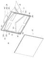
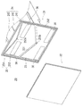
- FIG. 3 is an exploded perspective view of the detergent charging case 20.
- the detergent charging case 20 is composed of a resin case body 21 and a glass plate (case glass plate) 22 attached to the case body 21.
- the case body 21 is composed of a front cover portion 23 and a storage portion 24 extending behind the front cover portion 23.
- the storage unit 24 is divided into three storage rooms, that is, a liquid detergent storage room 241 for storing liquid detergent, a softener storage room 242 for storing liquid softener, and a powder detergent storage room 243 for storing powder detergent. Has been done.
- the arrangement of each storage room is an example, and may be another arrangement.
- the glass plate 22 is attached to the front surface of the detergent charging case 20, that is, the front surface side of the front cover portion 23 with double-sided tape 30 or the like.
- the glass plate 22 may be attached to the front cover portion 23 by applying an adhesive instead of the double-sided tape 30.
- the detergent charging case 20 has a structure for preventing water or detergent from entering the glass-attached surface.
- FIG. 4 is a vertical cross-sectional view of the vicinity of the front portion of the detergent charging case 20.
- the glass plate 22 is attached to the front side of the front cover portion 23 of the case body 21.
- a frame-shaped rib (frame-shaped rib for the case) 231 is provided on the front surface of the front cover portion 23 along the outer peripheral edge, and the glass plate 22 is fitted inside the frame-shaped rib 231 to cover the front surface. It is attached to the part 23. That is, the periphery of the glass plate 22 is surrounded by the frame-shaped rib 231.
- the thickness of the frame-shaped rib 231 is smaller than the thickness of the glass plate 22.
- the frame-shaped rib 231 is in a state of being retracted deeper than the surface of the glass plate 22, and is difficult for the user to see.
- the upper front surface of the washing machine main body 11 appears to the user to be formed only by the glass surfaces of the operation panel 13 and the detergent charging case 20, and the design of the washing machine 10 is improved.
- end surface of the glass plate 22 is usually cut so as to be perpendicular to the main surface of the glass.
- the end faces of the upper end edge and the lower end edge of the glass plate 22 are shown, and all of these end faces are formed on a surface perpendicular to the main surface of the glass.
- the front surface of the detergent charging case 20 has an inclined surface such that the upper side is lowered to the rear as compared with the lower side, as shown in FIG. 5A, at the lower end edge of the glass plate 22.
- the end face may be cut so as to be a horizontal plane. More specifically, the end surface of the lower end edge of the glass plate 22 is not perpendicular to the glass main surface, but at least the surface of the front cover portion 23 facing the frame-shaped rib 231 is a horizontal plane 221. It may be cut into. Further, the end surface of the glass plate 22 may be chamfered so as to have a C surface 222 on both sides of the glass plate 22 in order to prevent cracking or chipping of the end surface.
- the end surface at the lower end edge of the glass plate 22 may be cut into an inclined surface 223 that rises rearward, and even in this case, the end surface of the glass plate 22 may be cut into a horizontal plane. A similar effect can be obtained. Further, the end surface of the upper end edge of the glass plate 22 may be cut into an inclined surface that descends rearward.
- the inclined surface 223 in FIG. 5B is a surface formed by processing the C surface of the back surface of the glass plate 22 to be larger than that of the front surface.
- the glass plate 22 is attached to the front cover portion 23 by a double-sided tape 30 or the like.
- the adhesiveness of the double-sided tape 30 is lowered, and the glass plate 22 may be peeled off or dropped, as described above.
- most of the intrusion of water or detergent into the glass-attached surface can be prevented by the frame-shaped rib 231 surrounding the periphery of the glass plate 22.
- a groove portion 25 is provided on the front surface of the front cover portion 23.
- the groove portion 25 is formed of a first groove portion 251 and a second groove portion 252.
- the first groove portion 251 is formed so as to be inclined so that the position of the front cover portion 23 at the central portion in the left-right direction is high and the positions at both end portions are low. Further, the first groove portion 251 is provided above the sticking area of the double-sided tape 30, and in the example of FIG. 3, two first groove portions 251 are provided side by side in the vertical direction.
- the second groove portion 252 is formed so as to extend in the vertical direction on both sides of the front cover portion 23 in the left-right direction. Both ends of the first groove portion 251 are connected to the second groove portion 252, respectively.
- the invading water or detergent reaches the first groove portion 251 and is grooved. It flows through the inside along an inclination and is sent to the second groove portion 252. After that, the water or detergent flows downward along the second groove portion 252 and is discharged from the drain hole 253 provided at the lower end of the front cover portion 23. Further, water and detergent that have entered from the side edge of the glass plate 22 side can be discharged by the second groove portion 252.
- the drain hole 253 is finally opened to the inside of the detergent charging case 20, and the water and detergent released downward by the drain hole 253 are discharged from the drain hole 253 and then the front surface of the washing machine 10. It does not leak to the side.
- the groove portion 25 is provided around (at least upward and sideways) the sticking area (or the adhesive application area) of the double-sided tape 30, and water is provided along the groove portion 25. It is possible to prevent water and detergent from reaching the area where the double-sided tape 30 is attached within the glass attachment surface by allowing the water and detergent to flow and be discharged. As a result, it is possible to reliably prevent the adhesiveness of the double-sided tape 30 from being lowered due to the intrusion of water or detergent. Further, since water and detergent do not leak to the outside of the washing machine 10 or the surface of the machine body, the outside of the machine or the surface of the machine body are not polluted, and the labor for cleaning can be reduced. Further, if the detergent does not stain the surface of the airframe, it is not necessary to impart resistance to the detergent component in the airframe surface member, and the material of the airframe surface member can be selected with priority given to improving the appearance.
- the shape of the groove portion 25 is not limited to the example shown in FIG. 3, and the drainage hole 253 is not limited to the lower end of the front cover portion 23.
- FIG. 6 and 7 show a modified example of the groove portion 25.
- the groove portion 25 in this modified example is inclined so that the position at the central portion is low and the position at both ends is high, contrary to FIG. Therefore, the water that has flowed into the first groove portion 251 flows toward the center side along the first groove portion 251.
- Drainage holes 253 (253a and 253b) are provided at the lowest position (that is, the central portion in the left-right direction) of each first groove portion 251 from the drainage hole 253 to the back surface side of the front cover portion 23. Water is being drained.
- the upper drainage hole 253a is provided above the storage portion 24 on the back surface of the front cover portion 23. Therefore, the water discharged from the drain hole 253a flows into the storage portion 24 and does not leak to the front side of the washing machine 10.
- the lower drainage hole 253b is provided below the storage portion 24.
- the drain hole 253b is provided with a drain rib 254 protruding toward the inside of the detergent charging case 20. The discharge rib 254 is provided to prevent water discharged from the drain hole 253b from flowing along the back surface of the front cover portion 23 and leaking to the front side of the washing machine 10.
- the glass plate 22 in the detergent charging case 20 has a frame-shaped rib 231 attached along the outer peripheral edge thereof.
- an operation panel 13 is arranged next to the detergent charging case 20, but here, a touch panel is used for the operation panel 13, and a glass plate (glass plate for panel) 131 is also used on the front surface of the operation panel 13. (See FIGS. 9 to 11) is attached.
- a frame-shaped rib (panel frame-shaped rib) 132 is attached to the glass plate 131 in the operation panel 13 along the outer peripheral edge thereof, and the glass plate 131 is surrounded by the frame-shaped rib 132. It has been broken.
- FIG. 8 is a schematic view of the washing machine 10 as viewed from the front side.
- 9 to 11 are sectional views taken along the line AA in FIG. 8, showing different configuration examples of the frame-shaped rib 231 in the detergent charging case 20 and the frame-shaped rib 132 in the operation panel 13.
- the end surface and the back surface of the glass plate 131 are protected by the frame-shaped rib 132, so that the user's finger is inserted in the gap when the detergent charging case 20 is pulled out forward. It is possible to prevent the glass plate 131 from being pulled forward due to the entry of the glass plate 131 and the like. Further, since the end surface of the glass plate 131 is protected by the frame-shaped rib 132, even if the side surface of the detergent charging case 20 hits the side surface of the operation panel 13 when the detergent charging case 20 is moved back and forth, the glass is used. The end face of the plate 131 can be protected. Therefore, it is possible to prevent the glass plate 131 in the operation panel 13 from being displaced or damaged.
- the design of the washing machine 10 can be improved by devising the shapes of the frame-shaped ribs 231 in the detergent charging case 20 and the frame-shaped ribs 132 in the operation panel 13. The configuration will be described.
- the frame-shaped ribs 231 and the frame-shaped ribs 132 do not overlap each other when viewed from the front side of the washing machine 10. Therefore, there is a width of two ribs between the glass plate 22 in the detergent charging case 20 and the glass plate 131 in the operation panel 13. As a result, the gap between the glass plate 22 and the glass plate 131 becomes large, and the design of the washing machine 10 is deteriorated.
- the gap between the detergent charging case 20 and the operation panel 13 (the gap between the frame-shaped rib 231 and the frame-shaped rib 132) is formed linearly in the front-rear direction. Therefore, when the detergent charging case 20 is opened or closed, the liquid agent (liquid detergent or liquid softener) splashes in the detergent charging case 20, and the front side of the washing machine 10 is seen through the gap between the detergent charging case 20 and the operation panel 13. There is also a risk of leaking into.
- FIG. 10 shows an example of the configuration of the frame-shaped ribs 231 and the frame-shaped ribs 132 when the shapes are devised.
- a slope 231a is provided on the rear surface side of the side adjacent to the frame-shaped rib 132.
- a slope 132a is provided on the front surface side of the side adjacent to the frame-shaped rib 231.
- the slope 231a formed on the frame-shaped rib 231 and the slope 132a formed on the frame-shaped rib 132 are parallel to each other.
- the frame-shaped rib 231 and a part of the frame-shaped rib 132 can be arranged so as to overlap each other when viewed from the front side of the washing machine 10. ..
- the gap between the glass plate 22 in the detergent charging case 20 and the glass plate 131 in the operation panel 13 can be narrowed as compared with the example of FIG. 9, and the sense of unity between the glass plate 22 and the glass plate 131 is improved.
- the design of the washing machine 10 can be improved.
- the gap between the detergent charging case 20 and the operation panel 13 (the gap between the frame-shaped rib 231 and the frame-shaped rib 132) was not formed linearly in the front-rear direction, and a part of the gap was bent. It becomes a shape. Therefore, even if the liquid agent bounces in the detergent charging case 20 when the detergent charging case 20 is opened or closed, it is prevented that the liquid leaks from the gap between the detergent charging case 20 and the operation panel 13 to the front side of the washing machine 10. Can be prevented.
- FIG. 11 shows another configuration example of the frame-shaped rib 231 and the frame-shaped rib 132 when the shape is devised.
- a recess 231b is provided on the rear side of the side adjacent to the frame-shaped rib 132.
- a convex portion 132b is provided on the rear side of the side adjacent to the frame-shaped rib 231.
- the frame-shaped rib 231 and a part of the frame-shaped rib 132 may be arranged so as to overlap each other when viewed from the front side of the washing machine 10. can.
- the gap between the glass plate 22 and the glass plate 131 is narrowed to improve the design of the washing machine 10, and the liquid agent is discharged from the gap between the detergent charging case 20 and the operation panel 13. It is possible to prevent leakage to the front side of the washing machine 10.
- the frame-shaped rib 132 surrounds the glass plate 131, but in order to obtain the above effect, the frame-shaped rib 132 is at least the detergent charging case 20. It may be provided on the edge on the side adjacent to the glass plate 22.
Landscapes
- Engineering & Computer Science (AREA)
- Textile Engineering (AREA)
- Detail Structures Of Washing Machines And Dryers (AREA)
- Main Body Construction Of Washing Machines And Laundry Dryers (AREA)
Priority Applications (1)
| Application Number | Priority Date | Filing Date | Title |
|---|---|---|---|
| JP2022521897A JP7765385B2 (ja) | 2020-05-13 | 2021-05-10 | 洗濯機 |
Applications Claiming Priority (2)
| Application Number | Priority Date | Filing Date | Title |
|---|---|---|---|
| JP2020084516 | 2020-05-13 | ||
| JP2020-084516 | 2020-05-13 |
Publications (1)
| Publication Number | Publication Date |
|---|---|
| WO2021230187A1 true WO2021230187A1 (ja) | 2021-11-18 |
Family
ID=78525878
Family Applications (1)
| Application Number | Title | Priority Date | Filing Date |
|---|---|---|---|
| PCT/JP2021/017659 Ceased WO2021230187A1 (ja) | 2020-05-13 | 2021-05-10 | 洗濯機 |
Country Status (3)
| Country | Link |
|---|---|
| JP (1) | JP7765385B2 (https=) |
| CN (1) | CN113668195A (https=) |
| WO (1) | WO2021230187A1 (https=) |
Citations (7)
| Publication number | Priority date | Publication date | Assignee | Title |
|---|---|---|---|---|
| JPS5696784U (https=) * | 1979-12-26 | 1981-07-31 | ||
| JPH0322783U (https=) * | 1989-07-15 | 1991-03-08 | ||
| JP2001253236A (ja) * | 2000-03-10 | 2001-09-18 | Honda Motor Co Ltd | 傾斜した縁部を有する乗物用ガラス |
| JP2011000363A (ja) * | 2009-06-22 | 2011-01-06 | Panasonic Corp | ドラム式洗濯機 |
| JP2016050767A (ja) * | 2014-08-29 | 2016-04-11 | パナソニックIpマネジメント株式会社 | 冷蔵庫 |
| JP2016198225A (ja) * | 2015-04-09 | 2016-12-01 | パナソニックIpマネジメント株式会社 | 洗濯機 |
| JP2017205338A (ja) * | 2016-05-19 | 2017-11-24 | パナソニックIpマネジメント株式会社 | 洗濯機 |
Family Cites Families (7)
| Publication number | Priority date | Publication date | Assignee | Title |
|---|---|---|---|---|
| JPS5820099U (ja) * | 1981-07-31 | 1983-02-07 | 松下電工株式会社 | 門扉 |
| JP2004350984A (ja) * | 2003-05-29 | 2004-12-16 | Toshiba Corp | 洗濯乾燥機 |
| JP4415976B2 (ja) * | 2006-06-21 | 2010-02-17 | パナソニック株式会社 | 操作表示装置 |
| JP5017068B2 (ja) * | 2007-11-27 | 2012-09-05 | 三洋電機株式会社 | 電気洗濯機 |
| JP6587961B2 (ja) | 2016-03-15 | 2019-10-09 | 日本板硝子株式会社 | 合わせガラス |
| JP2021029724A (ja) | 2019-08-27 | 2021-03-01 | シャープ株式会社 | 洗濯機 |
| CN212163886U (zh) | 2020-03-31 | 2020-12-15 | 华为技术有限公司 | 电子设备 |
-
2021
- 2021-05-10 JP JP2022521897A patent/JP7765385B2/ja active Active
- 2021-05-10 CN CN202110506601.XA patent/CN113668195A/zh active Pending
- 2021-05-10 WO PCT/JP2021/017659 patent/WO2021230187A1/ja not_active Ceased
Patent Citations (7)
| Publication number | Priority date | Publication date | Assignee | Title |
|---|---|---|---|---|
| JPS5696784U (https=) * | 1979-12-26 | 1981-07-31 | ||
| JPH0322783U (https=) * | 1989-07-15 | 1991-03-08 | ||
| JP2001253236A (ja) * | 2000-03-10 | 2001-09-18 | Honda Motor Co Ltd | 傾斜した縁部を有する乗物用ガラス |
| JP2011000363A (ja) * | 2009-06-22 | 2011-01-06 | Panasonic Corp | ドラム式洗濯機 |
| JP2016050767A (ja) * | 2014-08-29 | 2016-04-11 | パナソニックIpマネジメント株式会社 | 冷蔵庫 |
| JP2016198225A (ja) * | 2015-04-09 | 2016-12-01 | パナソニックIpマネジメント株式会社 | 洗濯機 |
| JP2017205338A (ja) * | 2016-05-19 | 2017-11-24 | パナソニックIpマネジメント株式会社 | 洗濯機 |
Also Published As
| Publication number | Publication date |
|---|---|
| JPWO2021230187A1 (https=) | 2021-11-18 |
| CN113668195A (zh) | 2021-11-19 |
| JP7765385B2 (ja) | 2025-11-06 |
Similar Documents
| Publication | Publication Date | Title |
|---|---|---|
| US7216944B2 (en) | Dishwasher door assembly | |
| CN108286173B (zh) | 洗衣机 | |
| US12121196B2 (en) | Dishwasher | |
| WO2021230187A1 (ja) | 洗濯機 | |
| KR20180060506A (ko) | 식기 세척기 | |
| JP2012016371A (ja) | 食器洗浄機 | |
| JP7152134B2 (ja) | 冷却貯蔵庫 | |
| CA2373971C (en) | Deflector for rack | |
| DE102012209545A1 (de) | Geschirrspülmaschine | |
| CN216481123U (zh) | 一种烹饪设备 | |
| JP6719049B2 (ja) | 洗濯機 | |
| JP6755122B2 (ja) | 洗濯機 | |
| JP4212438B2 (ja) | 食器洗い機 | |
| JP2016158746A (ja) | 食器洗い機 | |
| TWI323165B (https=) | ||
| KR20230001297A (ko) | 의류처리장치 | |
| JP4609367B2 (ja) | 食器洗い機 | |
| JP6058605B2 (ja) | 食器洗浄機 | |
| JP7735293B2 (ja) | 洗濯機 | |
| KR101405286B1 (ko) | 세탁기 | |
| JPH10323244A (ja) | 流し用シンク | |
| JP4119643B2 (ja) | パチンコ機 | |
| JP6709969B2 (ja) | 厨房装置 | |
| CN112513361B (zh) | 滚筒式洗衣机 | |
| JP2006198223A (ja) | 食器洗浄機 |
Legal Events
| Date | Code | Title | Description |
|---|---|---|---|
| 121 | Ep: the epo has been informed by wipo that ep was designated in this application |
Ref document number: 21804697 Country of ref document: EP Kind code of ref document: A1 |
|
| ENP | Entry into the national phase |
Ref document number: 2022521897 Country of ref document: JP Kind code of ref document: A |
|
| NENP | Non-entry into the national phase |
Ref country code: DE |
|
| 122 | Ep: pct application non-entry in european phase |
Ref document number: 21804697 Country of ref document: EP Kind code of ref document: A1 |