WO2021229841A1 - 測定装置、測定方法、プログラム及びレコード盤 - Google Patents
測定装置、測定方法、プログラム及びレコード盤 Download PDFInfo
- Publication number
- WO2021229841A1 WO2021229841A1 PCT/JP2020/041626 JP2020041626W WO2021229841A1 WO 2021229841 A1 WO2021229841 A1 WO 2021229841A1 JP 2020041626 W JP2020041626 W JP 2020041626W WO 2021229841 A1 WO2021229841 A1 WO 2021229841A1
- Authority
- WO
- WIPO (PCT)
- Prior art keywords
- record
- recorded
- signal
- record board
- board
- Prior art date
- Legal status (The legal status is an assumption and is not a legal conclusion. Google has not performed a legal analysis and makes no representation as to the accuracy of the status listed.)
- Ceased
Links
Images





Classifications
-
- G—PHYSICS
- G11—INFORMATION STORAGE
- G11B—INFORMATION STORAGE BASED ON RELATIVE MOVEMENT BETWEEN RECORD CARRIER AND TRANSDUCER
- G11B20/00—Signal processing not specific to the method of recording or reproducing; Circuits therefor
- G11B20/02—Analogue recording or reproducing
- G11B20/025—Error detection or correction
-
- G—PHYSICS
- G11—INFORMATION STORAGE
- G11B—INFORMATION STORAGE BASED ON RELATIVE MOVEMENT BETWEEN RECORD CARRIER AND TRANSDUCER
- G11B20/00—Signal processing not specific to the method of recording or reproducing; Circuits therefor
- G11B20/10—Digital recording or reproducing
- G11B20/10009—Improvement or modification of read or write signals
- G11B20/10305—Improvement or modification of read or write signals signal quality assessment
- G11B20/10398—Improvement or modification of read or write signals signal quality assessment jitter, timing deviations or phase and frequency errors
-
- G—PHYSICS
- G11—INFORMATION STORAGE
- G11B—INFORMATION STORAGE BASED ON RELATIVE MOVEMENT BETWEEN RECORD CARRIER AND TRANSDUCER
- G11B23/00—Record carriers not specific to the method of recording or reproducing; Accessories, e.g. containers, specially adapted for co-operation with the recording or reproducing apparatus ; Intermediate mediums; Apparatus or processes specially adapted for their manufacture
- G11B23/30—Record carriers not specific to the method of recording or reproducing; Accessories, e.g. containers, specially adapted for co-operation with the recording or reproducing apparatus ; Intermediate mediums; Apparatus or processes specially adapted for their manufacture with provision for auxiliary signals
- G11B23/34—Signal means additional to the main recording track, e.g. photoelectric sensing of sprocket holes for timing
-
- G—PHYSICS
- G11—INFORMATION STORAGE
- G11B—INFORMATION STORAGE BASED ON RELATIVE MOVEMENT BETWEEN RECORD CARRIER AND TRANSDUCER
- G11B27/00—Editing; Indexing; Addressing; Timing or synchronising; Monitoring; Measuring tape travel
- G11B27/36—Monitoring, i.e. supervising the progress of recording or reproducing
-
- G—PHYSICS
- G11—INFORMATION STORAGE
- G11B—INFORMATION STORAGE BASED ON RELATIVE MOVEMENT BETWEEN RECORD CARRIER AND TRANSDUCER
- G11B3/00—Recording by mechanical cutting, deforming or pressing, e.g. of grooves or pits; Reproducing by mechanical sensing; Record carriers therefor
- G11B3/02—Arrangements of heads
- G11B3/10—Arranging, supporting, or driving of heads or of transducers relatively to record carriers
- G11B3/34—Driving or guiding during transducing operation
- G11B3/38—Guiding, e.g. constructions or arrangements providing linear or other special tracking characteristics
-
- G—PHYSICS
- G11—INFORMATION STORAGE
- G11B—INFORMATION STORAGE BASED ON RELATIVE MOVEMENT BETWEEN RECORD CARRIER AND TRANSDUCER
- G11B3/00—Recording by mechanical cutting, deforming or pressing, e.g. of grooves or pits; Reproducing by mechanical sensing; Record carriers therefor
- G11B3/68—Record carriers
Definitions
- the present disclosure relates to a measuring device, a measuring method, a program, and a record board for measuring various characteristics of a pickup cartridge (hereinafter, also referred to as a cartridge) in a record reproduction system or a transmission line between a turntable system and a phono equalizer.
- a pickup cartridge hereinafter, also referred to as a cartridge
- Patent Document 1 discloses a technique for measuring the characteristics of a record reproduction system that changes depending on various characteristics of a cartridge or the like by using a record board on which a raised cosine pulse waveform having a short pulse width is recorded.
- the characteristics of the record reproduction system are frequency characteristics (frequency amplitude characteristics, frequency phase characteristics, etc.) of an input signal input from a record player to a reproduction device including a phono equalizer and an amplifier.
- the present disclosure provides a measuring device or the like capable of effectively measuring the characteristics of a record reproduction system.
- the measuring device in the present disclosure is a measuring device in a record reproduction system including a record player and a measuring device, and includes a processor and a memory, and the processor executes a program stored in the memory.
- a plurality of recorded test signals input from the record player to the measuring device when a test signal for measuring the characteristics of the record reproduction system recorded on the record board is reproduced by the record player.
- the frequency characteristics of the plurality of input signals are measured according to the above, the measurement error between each of the measured frequency characteristics of the plurality of input signals and the predetermined frequency characteristics is calculated, and the frequency characteristics of the plurality of input signals are calculated. Among them, the frequency characteristic having the smallest measurement error is selected as the measurement result of the record reproduction system, and the selected measurement result is output.
- the measurement method in the present disclosure is a plurality of measurement methods input from the record player when a test signal for measuring the characteristics of the record reproduction system recorded on the record board is reproduced by the record player in the record reproduction system.
- the frequency characteristics of the plurality of input signals corresponding to the recorded test signals are measured, and the measurement error between each of the measured frequency characteristics of the plurality of input signals and a predetermined frequency characteristic is calculated, and the plurality of said. It includes a process of selecting the frequency characteristic having the smallest measurement error among the frequency characteristics of the input signal as the measurement result of the record reproduction system and outputting the selected measurement result.
- the program in the present disclosure is a program for causing a computer to execute the above measurement method.
- a plurality of test signals for measuring the characteristics of the record reproduction system are recorded in the sound groove within one lap.
- the characteristics of the record reproduction system can be effectively measured.
- FIG. 1 is a diagram showing an example of a configuration of a record reproduction system according to an embodiment.
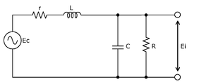
- FIG. 2 is a circuit diagram showing an example of a load and an equivalent circuit of a transmission line connecting the cartridge and the load in the moving magnet type cartridge.
- FIG. 3A is a top view showing an example of a vinyl record according to an embodiment.
- FIG. 3B is a cross-sectional view showing an example of a sound groove in which a test signal and a detection signal for detecting a reproduction speed are recorded.
- FIG. 4A is a top view showing another example of the record board according to the embodiment.
- FIG. 4B is a cross-sectional view showing another example of the sound groove in which the test signal and the detection signal for detecting the reproduction speed are recorded.
- FIG. 1 is a diagram showing an example of a configuration of a record reproduction system according to an embodiment.
- FIG. 2 is a circuit diagram showing an example of a load and an equivalent circuit of a transmission line connecting the cartridge and the load in the
- FIG. 5 is a flowchart showing an example of the operation of the measuring device according to the embodiment.
- FIG. 6 is a diagram for explaining a method of measuring the frequency characteristics of a plurality of input signals.
- FIG. 7A is a diagram for explaining a method of calculating a measurement error between each of the frequency characteristics of a plurality of input signals and a predetermined frequency characteristic.
- FIG. 7B is a diagram for explaining a method of selecting a measurement result.
- FIG. 7C is a diagram for explaining a specific example of the method of selecting the measurement result.
- FIG. 8 is a diagram for explaining the conversion of the sample rate.
- FIG. 1 is a diagram showing an example of the configuration of the record reproduction system 1 according to the embodiment.
- the record reproduction system 1 is a system for reproducing an analog record, and includes a record player 100, a reproduction device 10, and a speaker 80.
- the record player 100 is an audio device for reproducing a signal (for example, an audio signal) recorded on a record board, and includes a turntable 101 and a cartridge 102.
- the turntable 101 is a rotary table on which a record board is placed and rotates at a constant speed (specifically, rotates).
- the cartridge 102 is a pickup cartridge provided at the tip of a tone arm (not shown) and provided with a record needle that traces the sound groove of a record board mounted on a turntable 101.
- the cartridge has various configurations such as a moving magnet type or a moving coil type depending on its structure. Such a cartridge acquires a signal recorded in the sound groove of the record board as vibration via a record needle, generates a voltage by vibrating a magnet or a coil due to the acquired vibration, and converts it into an analog electric signal. And output.
- the cartridge 102 will be described as, for example, a moving magnet type cartridge.
- the speaker 80 converts the electric power of the signal output from the amplifier 70, which will be described later, into sound energy and outputs the sound to the space.
- the reproduction device 10 is a device that adjusts and amplifies the frequency characteristics of the input signal input from the record player 100 that reproduces the record board, and is a processor 20, a memory 30, a Phono equalizer 40, and an A / D converter. It includes 50, a D / A converter 60, and an amplifier 70.
- the reproduction device 10 is an example of a measuring device.
- the Phono equalizer 40 is an equalizer that corrects the frequency amplitude characteristic of the electric signal output from the cartridge 102 to a flat characteristic.
- a vinyl record is subjected to emphasis processing on the frequency at the time of cutting in order to effectively utilize the dynamic range. If the frequency characteristics of the sound source are not corrected and cutting is performed as it is, the amplitude becomes large in the low frequency range. Therefore, the amplitude limit of the cutter head is exceeded during cutting, and tracing during reproduction becomes difficult. On the other hand, in the high frequency range, the amplitude becomes small, so that the S / N ratio decreases. Therefore, the sound groove of the record board is corrected in advance so that the low frequency signal level is small and the high frequency signal level is high, and then cutting is performed.
- a characteristic curve defined by the RIAA Recording Industry Association of America
- the A / D converter 50 is a converter that converts an electric signal (analog signal) output from the Phono equalizer 40 into a digital signal.
- the A / D converter 50 outputs a digital signal.
- the D / A converter 60 is a converter that converts a signal (digital signal) whose frequency characteristics have been adjusted by a digital filter 13 described later into an analog signal.
- the D / A converter 60 outputs an analog signal.
- the amplifier 70 is an amplifier that amplifies the analog signal output from the D / A converter 60.
- the amplifier 70 may be, for example, a class D amplifier or the like.
- FIG. 2 is a circuit diagram showing an example of a load and an equivalent circuit of a transmission line connecting the cartridge 102 and the load in the moving magnet type cartridge 102.
- the input signal (input voltage Ei) to the reproduction device 10 is a value corresponding to the open output voltage Ec of the cartridge 102, the DC resistance r of the cartridge 102, the inductance L of the cartridge 102, the stray capacity C of the transmission line, and the load resistance R. That is, the frequency characteristics of the input signal to the reproduction device 10 vary according to these characteristics.
- the playback device 10 is also a device for measuring the characteristics of the record playback system 1, and specifically, as described above, the cartridge 102 included in the record player 100, the load connected to the cartridge 102, and the cartridge 102 and the load.
- the reproduction device 10 may also have a function of correcting the frequency characteristic according to the fluctuation.
- the function of measuring the characteristics of the record reproduction system 1 and the function of correcting the frequency characteristics of the reproduction device 10 are realized by the frequency characteristic measurement unit 11, the filter coefficient calculation unit 12, the digital filter 13, and the reproduction speed detection unit 14. Details of the frequency characteristic measurement unit 11, the filter coefficient calculation unit 12, the digital filter 13, and the reproduction speed detection unit 14 will be described later.
- the playback device 10 measures the characteristics of the record reproduction system 1
- a record board for measuring the characteristics of the record reproduction system 1 is placed on the turntable 101 and recorded on the record board for measurement, not for ornamental use.
- the test signal is played.
- the test signal is an SS signal such as a TSP signal.
- the SS signal is a signal whose energy is relatively increased by stretching the impulse signal in the time direction. In the SS signal, the frequency changes with time from low frequency to high frequency or from high frequency to low frequency. By using the SS signal, it is possible to perform measurement with a high S / N ratio.
- the tone arm vibrates up and down due to the warp of the record board, so that an appropriate stylus pressure is not applied to the record needle, and the record needle moves away from the record board, so that the sound groove cannot be traced accurately.
- the open output voltage Ec of is changed.
- the linear speed changes due to the position shift of the center hole of the record board (position shift of the center of the record board) or the change of the radius of the record board due to the track feed during the production of the record board (during cutting), and the playback speed of the sound source changes.
- FIG. 3A is a top view showing an example of the record board 200 according to the embodiment.
- FIG. 3B is a cross-sectional view showing an example of a sound groove in which a test signal and a detection signal for detecting a reproduction speed are recorded.
- the record board 200 is a record board dedicated to measuring the characteristics of the record reproduction system 1, and a plurality of (multiple times) test signals for measuring the characteristics of the record reproduction system 1 are recorded in the sound groove.
- the test signals recorded a plurality of times are the same signals, and are SS signals such as TSP signals.
- a test signal for measuring the characteristics of the record reproduction system 1 is recorded a plurality of times in the sound groove within one lap.
- 3A shows an example in which a test signal is recorded a plurality of times in a sound groove of about 1/4 lap. In this way, by recording the test signal a plurality of times in the sound groove within one lap, deterioration of the S / N ratio can be suppressed.
- the test signal is recorded on the record board 200 a plurality of times in the sound groove in the outer peripheral region of the record board 200. This is because the turntable 101 rotates at a constant rotation speed (for example, 331/3 rpm) in the turntable system, so that the linear velocity is slow in the inner peripheral region of the record board 200, and the test signal is in the inner peripheral region of the record board 200. This is because the S / N ratio becomes worse when the record is recorded in the sound groove.
- the sound groove in the outer peripheral region of the record board 200 is a sound groove at a position separated from the center of the record board 200 toward the outer periphery of the record board 200 by more than half of the radius of the record board 200.
- R2 which is the distance from the center of the record board 200 to the sound groove where the test signal is recorded, is larger than half of R1 which is the radius of the record board 200, and the position of R2.
- a test signal such as an SS signal is recorded multiple times in the sound groove of.
- the record board 200 detects the reproduction speed on the record board 200 at a position adjacent to the outer peripheral side or the inner peripheral side of the record board 200 with respect to the position of the sound groove in which the test signal is recorded a plurality of times.
- the signal is recorded.
- the detection signal is a single frequency sine wave signal, and is recorded so as to have a known frequency (for example, 1 kHz) when the record board 200 is played back at a known rotation speed such as 331/3 rpm.
- the period of the sine wave signal can be calculated in advance.
- the reproduction speed can be obtained by comparing with the period of the wave signal. For example, the number of samples between adjacent zero cross points of a sine wave signal when the record board 200 is played at an unknown rotation speed and the adjacent sine wave signal when the record board 200 is played at a known playback speed.
- the sample rate conversion rate is calculated using the number of samples between the zero cross points (for example, stored in advance in a memory or the like), and the sample rate conversion is performed.
- the test signal is recorded multiple times at a position adjacent to the position of the sound groove in which the detection signal is recorded.
- the change in the radius of the record due to the misalignment of the center hole of the record, or the change in the radius of the record due to the track feed during cutting of the record can be regarded as equal if it is an adjacent sound groove. .. Therefore, by detecting the reproduction speed (number of samples) in the sound groove in which the detection signal is recorded on the record board 200, the sound groove in which the test signal adjacent to the sound groove in which the detection signal is recorded is recorded is recorded. The playback speed can be measured.
- FIGS. 3A and 3B show an example in which a detection signal is recorded in a sound groove adjacent to the outer peripheral side of the record board 200 with respect to a sound groove in which the test signal is recorded a plurality of times.
- the detection signal is recorded in the channel on the outer peripheral side of the sound groove (right channel (referred to as Rch in the drawing)).
- Rch right channel
- Lch left channel of the sound groove
- the right channel is better than the left channel in the sound groove in which the detection signal is recorded.
- the test signal is far from the recorded sound groove.
- the record board 200 records a detection signal for detecting the reproduction speed on the record board 200 in a sound groove adjacent to the inner peripheral side of the record board 200 with respect to the sound groove in which the test signal is recorded a plurality of times. You may. This will be described with reference to FIGS. 4A and 4B.
- FIG. 4A is a top view showing another example of the record board 200 according to the embodiment.
- FIG. 4B is a cross-sectional view showing another example of the sound groove in which the test signal and the detection signal for detecting the reproduction speed are recorded.
- FIGS. 4A and 4B show an example in which a detection signal is recorded in a sound groove adjacent to the inner peripheral side of the record board 200 with respect to a sound groove in which the test signal is recorded a plurality of times.
- the detection signal is recorded in the channel (left channel) on the inner peripheral side of the sound groove.
- the channel on the left side of the right channel in the sound groove in which the detection signal is recorded is recorded. It is farther from the sound groove where the test signal was recorded. As a result, the influence of the detection signal on the test signal can be suppressed, and the deterioration of the S / N ratio can be suppressed.
- the detection signal When the detection signal is recorded in the sound groove adjacent to the outer peripheral side of the record board 200 with respect to the sound groove in which the test signal is recorded multiple times, the detection signal can be reproduced before the test signal, so that the sample rate The conversion rate can be determined first, then the test signal can be reproduced, and sample rate conversion can be performed in real time. Therefore, the detection signal is recorded in the sound groove adjacent to the outer peripheral side of the record board 200, as compared with the case where the detection signal is recorded in the sound groove adjacent to the inner peripheral side of the record board 200 with respect to the sound groove in which the test signal is recorded a plurality of times. It is better to be recorded.
- the test signal is once reproduced and stored in a memory or the like. Next, the detection signal is reproduced, the sample rate conversion rate is determined, and the sample rate conversion is performed.
- the test signal and the detection signal may be recorded so as to face each other on the right channel and the left channel of the same sound groove.
- the reproduction device 10 is a computer having a processor 20 (for example, a DSP (Digital Signal Processor)), a memory 30, and the like.
- the memory is a ROM (Read Only Memory), a RAM (Random Access Memory), or the like, and can store a program executed by the processor.
- the frequency characteristic measurement unit 11, the filter coefficient calculation unit 12, the digital filter 13, and the reproduction speed detection unit 14 are realized by a processor 20 or the like that executes a program stored in the memory 30.
- the frequency characteristic measuring unit 11 is a test detected by the reproduction speed detecting unit 14 when the test signal for measuring the characteristics of the record reproducing system 1 recorded on the record board 200 a plurality of times is reproduced by the record player 100. Based on the signal reproduction speed, the sample rate of the test signal is converted and converted into a test signal with no deviation in the reproduction speed. After that, the frequency characteristic measuring unit 11 measures the frequency characteristics of a plurality of input signals corresponding to the test signals recorded a plurality of times input from the record player 100 to the reproduction device 10, and the frequency characteristic measuring unit 11 of the measured plurality of input signals.
- the measurement error between each of the frequency characteristics and the predetermined frequency characteristics is calculated, and the frequency characteristic having the smallest measurement error among the frequency characteristics of the plurality of input signals is selected as the measurement result of the record reproduction system 1, and the selected measurement is performed. Output the result.
- the details of the frequency characteristic measuring unit 11 will be described later with reference to FIGS. 5 to 7C.
- the filter coefficient calculation unit 12 calculates the filter coefficient of the digital filter 13 based on the measurement result output from the frequency characteristic measurement unit 11. For example, when the frequency characteristic indicated by the measurement result for the desired frequency characteristic is too high or too low at a specific frequency, the frequency characteristic indicated by the measurement result approaches the desired frequency characteristic. Calculate the coefficient. The filter coefficient calculation unit 12 outputs the calculated filter coefficient to the digital filter 13.
- the digital filter 13 is a filter that adjusts the frequency characteristics of the input signal input from the record player 100 to the playback device 10 according to the filter coefficient calculated by the filter coefficient calculation unit 12.
- the digital filter 13 is an FIR (Finite Impulse Response) filter.
- the reproduction speed detection unit 14 detects the reproduction speed at the position where the test signal on the record board 200 is recorded a plurality of times based on the detection signal recorded on the record board 200.
- the detection signal for example, a 1 kHz sine wave is used.
- the reproduction speed detection unit 14 calculates the time of a half cycle of the sine wave at each zero cross point of the sine wave and compares it with the period of the known sine wave to detect the time lag. The details of the reproduction speed detection unit 14 will be described later with reference to FIG.
- FIG. 5 is a flowchart showing an example of the operation of the reproduction device 10 (specifically, the frequency characteristic measurement unit 11) according to the embodiment.
- the playback device 10 performs the operation shown in FIG. ..
- the reproduction device 10 is a plurality of test signals recorded a plurality of times on the record board 200 according to the test signals recorded a plurality of times, which are input from the record player 100 to the reproduction device 10 when the test signal is reproduced by the record player 100.
- the frequency characteristic of the input signal of (step S11) is measured. This will be described with reference to FIG.
- FIG. 6 is a diagram for explaining a method of measuring the frequency characteristics of a plurality of input signals.
- test signals As shown in FIG. 6, for example, it is assumed that five test signals (SS signals) are recorded in the left channel of the sound groove of the record board 200, and five test signals are recorded in the right channel.
- a trigger signal may be recorded in the sound groove of the record board 200.
- the trigger signal can recognize the start and end timings of the test signal on the record board 200.
- An example is shown in which the test signal recorded on the left channel is measured first, then the test signal recorded on the right channel is measured, but first the test signal recorded on the right channel is measured, and then the test signal recorded on the right channel is measured.
- the test signal recorded on the left channel may be measured.
- a test signal may be recorded in the right channel and the left channel facing each other in the sound groove, and the test signal recorded in the right channel and the test signal recorded in the left channel may be measured at the same time.
- the reproduction device 10 outputs a test signal from a plurality of input signals corresponding to the test signals recorded a plurality of times, which are input to the reproduction device 10 from the record player 100 that reproduces the test signal recorded a plurality of times on the record board 200. Extract. At that time, the reproduction device 10 performs sample rate conversion of the extracted test signal based on the reproduction speed of the test signal detected by the reproduction speed detection unit 14, and converts it into a test signal having no deviation of the reproduction speed. The reproduction device 10 performs a convolution calculation of the test signal after the sample rate conversion with the test signal cut on the recording board 200 for measurement and the signal having a complex conjugate (for example, an inverse TSP signal).
- a complex conjugate for example, an inverse TSP signal
- the impulse response that combines the input impedance of the cartridge 102, the transmission line, and the load is estimated.
- the reproduction device 10 acquires frequency characteristics (specifically, frequency amplitude characteristics and frequency phase characteristics) by performing an FFT (Fast Fourier Transform) on the estimated impulse response.
- the reproduction device 10 performs the above processing in the same manner for each of the test signals recorded a plurality of times on the record board 200, and acquires the frequency characteristics of each.
- a measurement error may occur in the measurement result of any one of the test signals recorded a plurality of times.
- the test signal since the test signal is recorded a plurality of times on the record board 200, it is possible to reduce the influence of the measurement error by selecting and adopting the frequency characteristic having a small measurement error.
- the reproduction device 10 next calculates the measurement error between each of the measured frequency characteristics of the plurality of input signals and the predetermined frequency characteristics (step S12).
- the predetermined frequency characteristics For example, in the example of the moving magnet type cartridge 102 of FIG. 2, in the equivalent circuit of the cartridge 102, the load, and the transmission line connecting the cartridge 102 and the load, the inductance of the cartridge 102, the stray capacitance of the transmission line, and the load resistance are used. A peak occurs in the frequency amplitude characteristic at the resonance frequency of the determined circuit, but it is expected that the frequency characteristic becomes flat in other frequency bands. In the moving magnet type cartridge 102, the resonance frequency of the circuit is generally generated between about 5 kHz and 20 kHz.
- the reproduction device 10 calculates the measurement error of the band other than the resonance frequency from the frequency characteristic results acquired from the test signals recorded a plurality of times, and determines the frequency characteristic having the smallest measurement error. It is selected as the measurement result of the record reproduction system 1 (step S13). This will be described with reference to FIGS. 7A and 7B.
- FIG. 7A is a diagram for explaining a method of calculating a measurement error between each of the frequency characteristics of a plurality of input signals and a predetermined frequency characteristic.
- the upper side of FIG. 7A shows a plurality of input signals corresponding to the test signals recorded a plurality of times input from the record player 100 to the playback device 10, and the lower side of FIG. 7A shows the frequencies of the plurality of input signals.
- the characteristics here, as an example, the frequency amplitude characteristic
- FIG. 7B is a diagram for explaining a method of selecting a measurement result.
- five input signals are shown on the upper side of FIG. 7A.
- the five input signals correspond to the five test signals recorded on the record board 200. Since the five test signals recorded on the record board 200 are the same signals, ideally, the five input signals also have the same waveform. However, it can be seen that, for example, due to the influence of the warp of the record board 200, the waveform of the second input signal from the left is significantly different from that of the other input signals. Correspondingly, as shown in the lower part of FIG. 7A, it can be seen that the second frequency amplitude characteristic from the left (measurement result 2) is significantly different from the other frequency amplitude characteristics.
- the predetermined frequency characteristic is the frequency characteristic (frequency amplitude characteristic) of the input signal from the record player 100 that reproduces the test signal to the reproduction device 10, which is assumed when the record player 100 and the record board 200 are not affected. And frequency phase characteristics). That is, the predetermined frequency characteristic is the frequency characteristic of the ideal input signal input to the reproduction device 10 when the record player 100 reproduces the test signal. For example, when there is a change in the frequency characteristic different from the peak dip of the frequency amplitude characteristic caused by the input impedance of the cartridge 102, the transmission line and the load, the frequency of the input signal from the record player 100 that reproduces the test signal to the reproduction device 10. The measurement error between the characteristic and the predetermined frequency characteristic becomes large.
- the reproduction device 10 calculates the measurement error between each of the five frequency amplitude characteristics and the predetermined frequency amplitude characteristic as shown in FIG. 7B, and the frequency amplitude characteristic (measurement) having the smallest measurement error among the five frequency amplitude characteristics. Result 4) is selected as the measurement result of the record reproduction system 1.
- the frequency amplitude characteristic (measurement) having the smallest measurement error among the five frequency amplitude characteristics.
- Result 4 is selected as the measurement result of the record reproduction system 1.
- FIG. 7C a specific example of the method of selecting the measurement result will be described with reference to FIG. 7C.
- FIG. 7C is a diagram for explaining a specific example of the method of selecting the measurement result.
- the reproduction device 10 divides the band into frequency octaves (for example, every octave) with respect to the frequency amplitude characteristics (solid line) measured as shown in FIG. 7C, and the frequency characteristics (broken line) of the ideal input signal. Calculate the error with.
- the reproduction device 10 calculates the total error of each octave, and among the measurement results of the plurality of input signals acquired from the test signals recorded a plurality of times, the input signal having the smallest total error is used as the measurement result. select.
- FIG. 7C shows an example in which the measurement result is selected by paying attention to the amplitude characteristic, but the measurement result may be selected by paying attention to the phase characteristic in the same manner.
- FIG. 8 is a diagram for explaining the conversion of the sample rate.
- the sample rate conversion using the detection signal adjacent to the test signal can offset such a time lag as shown in the lower part of FIG. 8, and the reproduction speed can be offset. Can be returned to the original playback speed.
- the recording start position (angle) of the detection signal and the recording start position of the test signal are the same, and the recording end position (angle) of the detection signal is set.
- the detection signal and the test signal are recorded in the adjacent sound grooves with a difference of one lap so that the recording end position of the test signal is the same. Therefore, the sample rate conversion rate obtained from the detection signal can be associated with the test signal.
- a sine wave signal is used as the detection signal, and the number of samples (Ni (i is a natural number)) for each time interval (half cycle of the sine wave signal) of the zero crossing point of the detection signal is calculated from the change in the amplitude of the detection signal. Will be done.
- the number of samples for each half cycle of the detection signal is associated with the position corresponding to the detection signal from the recording start position to the recording end position of the test signal. For example, by arranging the trigger signals at the beginning and the end of each of the detection signal and the test signal, the number of samples is associated with each other based on the positions of the trigger signals.
- the trigger signal may not be arranged, and for example, the association may be made based on the timing at which the signal starts to be detected from the silent state.
- the ideal sample number M for each half cycle of the detection signal is recorded in a memory, for example, as known, and the conversion rate M is the section in the test signal corresponding to each half cycle of the detection signal.
- Sample rate conversion is performed with / Ni.
- this section becomes 100 samples, which can be converted into an ideal number of samples. That is, the sample rate conversion is performed so that the original reproduction speed is obtained for this section.
- the sample rate conversion is similarly applied to each section corresponding to the half cycle of the detection signal. Since the time interval of the zero cross point can be obtained for each half cycle of the sine wave, the reproduction speed (that is, the number of samples) can also be obtained for each half cycle of the sine wave. By converting the sample rate according to the acquired playback speed, it is possible to accurately return to the original number of data without any deviation in the playback speed. In order to shorten the calculation time, the sample rate may be converted using the average value of a plurality of cycles instead of the half cycle of the sine wave.
- the number of samples when the detection signal is reproduced from the beginning to the end may be N, the ideal number of samples at this time may be M, and the entire test signal may be sample rate converted at a conversion rate of M / N.
- the detection signal may be any signal whose amplitude can be detected, and may be white noise, a pulse signal, or the like.
- the detection signal may be silent (no signal) in addition to the detection signal that can be selected when the trigger signal is not arranged.
- the reproduction device 10 then outputs the selected measurement result (step S14).
- the filter coefficient calculation unit 12 can calculate the filter coefficient of the digital filter 13 based on the frequency characteristics that are less affected by the record player 100 and the record board 200.
- the playback device 10 in the record playback system 1 including the record player 100 and the playback device 10 includes a processor 20 and a memory 30, and the processor 20 contains a program stored in the memory 30.
- a plurality of test signals for measuring the characteristics of the record reproduction system 1 recorded on the record board 200 are input from the record player 100 to the reproduction device 10 when the record player 100 reproduces the test signals.
- the frequency characteristics of a plurality of input signals corresponding to the recorded test signals are measured, the measurement error between each of the measured frequency characteristics of the plurality of input signals and a predetermined frequency characteristic is calculated, and the frequency characteristics of the plurality of input signals are calculated.
- the frequency characteristic having the smallest measurement error is selected as the measurement result of the record reproduction system 1, and the selected measurement result is output.
- the frequency characteristic having the smallest measurement error that is, the frequency characteristic having the smallest measurement error, that is, the frequency that can be measured accurately without selecting the frequency characteristic having the measurement error as the measurement result of the record reproduction system 1.
- the characteristics can be selected as the measurement result of the record reproduction system 1. Therefore, the characteristics of the record reproduction system can be effectively measured.
- test signal may be an SS signal.
- the record board 200 is for detecting the reproduction speed on the record board 200 at a position adjacent to the outer peripheral side or the inner peripheral side of the record board 200 with respect to the position of the sound groove in which a plurality of test signals are recorded.
- the detection signal is recorded, and the reproduction device 10 detects the reproduction speed at the position where a plurality of test signals are recorded on the record board 200 based on the detection signal, and the record reproduction system 1 according to the detected reproduction speed.
- the sample rate of may be converted.
- the change can be offset and the measurement error can be reduced.
- a plurality of test signals for measuring the characteristics of the record reproduction system 1 are recorded in the sound groove within one lap.
- a plurality of test signals for measuring the characteristics of the record reproduction system 1 are recorded on the record board 200, and the probability that all the test signal measurements fail is low. Therefore, when the reproduction device 10 or the like measures the characteristics of the record reproduction system 1 using the record board 200, the characteristics of the record reproduction system 1 can be effectively measured. Since a plurality of test signals are recorded in the sound grooves within one lap, interference between adjacent sound grooves in the radial direction is less likely to occur, and deterioration of the S / N ratio can be suppressed.
- test signal may be an SS signal.
- a plurality of test signals may be recorded in the sound groove in the outer peripheral region of the record board 200.
- the record board 200 is for detecting the reproduction speed on the record board 200 at a position adjacent to the outer peripheral side or the inner peripheral side of the record board 200 with respect to the position of the sound groove in which a plurality of test signals are recorded.
- the detection signal may be recorded.
- the detection signal may be recorded on the wall of the right channel in the sound groove adjacent to the outer peripheral side of the record board 200 with respect to the sound groove in which a plurality of test signals are recorded.
- the detection signal may be recorded on the wall of the left channel in the sound groove adjacent to the inner peripheral side of the record board 200 with respect to the sound groove in which a plurality of test signals are recorded.
- test signal is an SS signal
- the present invention is not limited to this.
- the test signal is not particularly limited as long as it is a known signal including a frequency component to be measured (for example, ordinary music, white noise, pink noise, etc.).
- the reproduction speed detection signal is recorded on the record board 200
- the reproduction speed detection signal may not be recorded on the record board 200.
- the reproduction device 10 includes the reproduction speed detection unit 14
- the reproduction device 10 may not include the reproduction speed detection unit 14.
- the present disclosure can be realized not only as a reproduction device 10, but also as a measurement method including steps (processes) performed by the components constituting the reproduction device 10.
- the measurement method is when a plurality of test signals recorded on a record board for measuring the characteristics of a record reproduction system are reproduced by a record player in the record reproduction system.
- the frequency characteristics of a plurality of input signals input from the record player according to the plurality of recorded test signals are measured (step S11), and each of the frequency characteristics of the measured plurality of input signals and a predetermined frequency characteristic are measured.
- Step S12 the frequency characteristic with the smallest measurement error among the frequency characteristics of the plurality of input signals is selected as the measurement result of the record reproduction system (step S13), and the selected measurement result is output.
- Step S14 is included.
- the measurement method may be executed by a computer (computer system). Then, the present disclosure can be realized as a program for causing a computer to execute the steps included in the measurement method. Further, the present disclosure can be realized as a non-temporary computer-readable recording medium such as a CD-ROM in which the program is recorded.
- each step is executed by executing the program using hardware resources such as a computer CPU, memory, and input / output circuit. .. That is, each step is executed by the CPU acquiring data from the memory or the input / output circuit or the like and performing an operation, or outputting the calculation result to the memory or the input / output circuit or the like.
- hardware resources such as a computer CPU, memory, and input / output circuit. .. That is, each step is executed by the CPU acquiring data from the memory or the input / output circuit or the like and performing an operation, or outputting the calculation result to the memory or the input / output circuit or the like.
- the component included in the reproduction device 10 of the above embodiment may be realized as an LSI (Large Scale Integration) which is an integrated circuit (IC: Integrated Circuit).
- LSI Large Scale Integration
- IC integrated circuit
- the integrated circuit is not limited to the LSI, and may be realized by a dedicated circuit or a general-purpose processor.
- a programmable FPGA or a reconfigurable processor in which the connections and settings of the circuit cells inside the LSI can be reconfigured may be utilized.
- the components described in the attached drawings and the detailed description may include not only the components essential for solving the problem but also the components not essential for solving the problem. Therefore, the fact that those non-essential components are described in the accompanying drawings or detailed description should not immediately determine that those non-essential components are essential.
- This disclosure can be applied to a device or the like for measuring the characteristics of a record reproduction system.
Landscapes
- Engineering & Computer Science (AREA)
- Signal Processing (AREA)
- Signal Processing For Digital Recording And Reproducing (AREA)
- Testing Electric Properties And Detecting Electric Faults (AREA)
- Testing, Inspecting, Measuring Of Stereoscopic Televisions And Televisions (AREA)
- Signal Processing Not Specific To The Method Of Recording And Reproducing (AREA)
Priority Applications (4)
| Application Number | Priority Date | Filing Date | Title |
|---|---|---|---|
| JP2022522502A JP7254244B2 (ja) | 2020-05-11 | 2020-11-06 | 測定装置、測定方法及びプログラム |
| US17/908,865 US12211518B2 (en) | 2020-05-11 | 2020-11-06 | Measurement device, measurement method, recording medium, and phonograph record |
| CN202080097896.3A CN115244620B (zh) | 2020-05-11 | 2020-11-06 | 测定装置、测定方法以及记录介质 |
| EP20935356.4A EP4152323B1 (en) | 2020-05-11 | 2020-11-06 | MEASURING DEVICE, MEASURING METHOD, PROGRAM, AND PHONOGRAPHIC DISC |
Applications Claiming Priority (2)
| Application Number | Priority Date | Filing Date | Title |
|---|---|---|---|
| JP2020-083084 | 2020-05-11 | ||
| JP2020083084 | 2020-05-11 |
Publications (1)
| Publication Number | Publication Date |
|---|---|
| WO2021229841A1 true WO2021229841A1 (ja) | 2021-11-18 |
Family
ID=78525606
Family Applications (1)
| Application Number | Title | Priority Date | Filing Date |
|---|---|---|---|
| PCT/JP2020/041626 Ceased WO2021229841A1 (ja) | 2020-05-11 | 2020-11-06 | 測定装置、測定方法、プログラム及びレコード盤 |
Country Status (5)
| Country | Link |
|---|---|
| US (1) | US12211518B2 (https=) |
| EP (1) | EP4152323B1 (https=) |
| JP (1) | JP7254244B2 (https=) |
| CN (1) | CN115244620B (https=) |
| WO (1) | WO2021229841A1 (https=) |
Cited By (1)
| Publication number | Priority date | Publication date | Assignee | Title |
|---|---|---|---|---|
| EP4195696A4 (en) * | 2020-08-05 | 2024-02-21 | Panasonic Intellectual Property Management Co., Ltd. | Voice signal processing device, voice signal processing method, and program |
Citations (7)
| Publication number | Priority date | Publication date | Assignee | Title |
|---|---|---|---|---|
| JPS5494206U (https=) * | 1977-12-15 | 1979-07-04 | ||
| JPS5611650A (en) * | 1979-07-10 | 1981-02-05 | Sony Corp | Record player |
| JPS5620398A (en) * | 1979-07-27 | 1981-02-25 | Hitachi Ltd | Electronic control tone arm |
| JPS5787317U (https=) * | 1980-11-14 | 1982-05-29 | ||
| JPS5833605A (ja) | 1981-08-21 | 1983-02-26 | 近畿瓦斯工事株式会社 | アスフアルト舗装材の再生車 |
| JPH11177362A (ja) * | 1997-12-11 | 1999-07-02 | Nippon Hoso Kyokai <Nhk> | 音響出力装置 |
| JP2005182932A (ja) * | 2003-12-19 | 2005-07-07 | Marantz Japan Inc | ディジタル信号再生システム |
Family Cites Families (15)
| Publication number | Priority date | Publication date | Assignee | Title |
|---|---|---|---|---|
| US3019024A (en) * | 1957-05-17 | 1962-01-30 | Feinstein Jack | Phonograph test method |
| JPS5833605B2 (ja) | 1974-11-05 | 1983-07-21 | 日本ビクター株式会社 | ピツクアツプカ−トリツジノ ヒヨウカソクテイヨウレコ−ド オヨビ ソノセイゾウホウホウ |
| US4186281A (en) * | 1976-10-22 | 1980-01-29 | Victor Company Of Japan, Ltd. | Multichannel record disc reproducing apparatus |
| US4306113A (en) * | 1979-11-23 | 1981-12-15 | Morton Roger R A | Method and equalization of home audio systems |
| US4410970A (en) * | 1981-06-19 | 1983-10-18 | Keysor-Century Corporation | Method and apparatus for measuring and analyzing sound characteristics of record discs |
| US4602359A (en) * | 1983-07-29 | 1986-07-22 | Rca Corporation | Method for determining variations from flatness in the topography of a disc surface |
| US4773094A (en) * | 1985-12-23 | 1988-09-20 | Dolby Ray Milton | Apparatus and method for calibrating recording and transmission systems |
| US5740146A (en) * | 1996-10-22 | 1998-04-14 | Disney Enterprises, Inc. | Method and apparatus for reducing noise using a plurality of recording copies |
| JP2001319328A (ja) * | 2000-05-08 | 2001-11-16 | Funai Electric Co Ltd | ディスクプレーヤの再生性能測定装置 |
| CN100351913C (zh) * | 2002-10-23 | 2007-11-28 | 松下电器产业株式会社 | 光盘装置 |
| JP4297360B2 (ja) * | 2004-09-27 | 2009-07-15 | パナソニック株式会社 | 光ディスク装置 |
| US20110080674A1 (en) * | 2009-10-02 | 2011-04-07 | Joel Durand | Magnetic azimuth adjustment for tonearm |
| JP5112545B1 (ja) * | 2011-07-29 | 2013-01-09 | 株式会社東芝 | 情報処理装置および同装置の音響信号処理方法 |
| JP7059200B2 (ja) * | 2016-05-04 | 2022-04-25 | クーランス・インコーポレイテッド | トーンアームトラッキングシステム、及びトーンアームをガイドする方法 |
| US10290316B1 (en) * | 2018-06-08 | 2019-05-14 | Hanpin Electron Co., Ltd. | Detection system of vinyl record player for detecting end of playback |
-
2020
- 2020-11-06 JP JP2022522502A patent/JP7254244B2/ja active Active
- 2020-11-06 CN CN202080097896.3A patent/CN115244620B/zh active Active
- 2020-11-06 EP EP20935356.4A patent/EP4152323B1/en active Active
- 2020-11-06 US US17/908,865 patent/US12211518B2/en active Active
- 2020-11-06 WO PCT/JP2020/041626 patent/WO2021229841A1/ja not_active Ceased
Patent Citations (7)
| Publication number | Priority date | Publication date | Assignee | Title |
|---|---|---|---|---|
| JPS5494206U (https=) * | 1977-12-15 | 1979-07-04 | ||
| JPS5611650A (en) * | 1979-07-10 | 1981-02-05 | Sony Corp | Record player |
| JPS5620398A (en) * | 1979-07-27 | 1981-02-25 | Hitachi Ltd | Electronic control tone arm |
| JPS5787317U (https=) * | 1980-11-14 | 1982-05-29 | ||
| JPS5833605A (ja) | 1981-08-21 | 1983-02-26 | 近畿瓦斯工事株式会社 | アスフアルト舗装材の再生車 |
| JPH11177362A (ja) * | 1997-12-11 | 1999-07-02 | Nippon Hoso Kyokai <Nhk> | 音響出力装置 |
| JP2005182932A (ja) * | 2003-12-19 | 2005-07-07 | Marantz Japan Inc | ディジタル信号再生システム |
Non-Patent Citations (1)
| Title |
|---|
| See also references of EP4152323A4 |
Cited By (1)
| Publication number | Priority date | Publication date | Assignee | Title |
|---|---|---|---|---|
| EP4195696A4 (en) * | 2020-08-05 | 2024-02-21 | Panasonic Intellectual Property Management Co., Ltd. | Voice signal processing device, voice signal processing method, and program |
Also Published As
| Publication number | Publication date |
|---|---|
| US20230109304A1 (en) | 2023-04-06 |
| JP7254244B2 (ja) | 2023-04-07 |
| CN115244620B (zh) | 2025-04-08 |
| CN115244620A (zh) | 2022-10-25 |
| EP4152323A4 (en) | 2023-10-11 |
| EP4152323A1 (en) | 2023-03-22 |
| EP4152323B1 (en) | 2025-12-31 |
| JPWO2021229841A1 (https=) | 2021-11-18 |
| US12211518B2 (en) | 2025-01-28 |
Similar Documents
| Publication | Publication Date | Title |
|---|---|---|
| US7961893B2 (en) | Measuring apparatus, measuring method, and sound signal processing apparatus | |
| CN101608947B (zh) | 声音测试方法 | |
| CN101448186B (zh) | 扬声器音效自动调整系统及方法 | |
| CN101416533A (zh) | 在音频系统中的方法和设备 | |
| WO2020175175A2 (en) | Phase control device, acoustic device and phase control method | |
| JP7254244B2 (ja) | 測定装置、測定方法及びプログラム | |
| JP6751810B2 (ja) | 音声処理装置および音声処理方法 | |
| JP2012002858A (ja) | タイムスケーリング方法、ピッチシフト方法、オーディオデータ処理装置およびプログラム | |
| JP6235198B2 (ja) | 音声信号処理方法、音声信号処理装置およびプログラム | |
| JP6118522B2 (ja) | タイムスケーリング方法、ピッチシフト方法、オーディオデータ処理装置およびプログラム | |
| CN102435303B (zh) | 声音测试方法 | |
| CN102435304B (zh) | 声音测试方法 | |
| JP5199915B2 (ja) | 音場補正方法及び音場補正装置 | |
| JPH10111693A (ja) | 音響特性測定用記録媒体、音響特性測定装置及び音響特性測定方法 | |
| WO2010146624A1 (ja) | 音声信号処理装置のタイムスケーリング方法、音声信号処理装置のピッチシフト方法、音声信号処理装置およびプログラム | |
| JP2005323204A (ja) | モーショナルフィードバック装置 | |
| JP4961402B2 (ja) | 磁気ヘッドまたは磁気ディスクの検査装置及び検査方法 | |
| WO2017135350A1 (ja) | 記録媒体、音響処理装置および音響処理方法 | |
| CN111314536B (zh) | 一种用于检测终端设备的收听模块的方法及设备 | |
| TWI403188B (zh) | 揚聲器音效自動調整系統及方法 | |
| CN115278507B (zh) | 左右声道缺陷检测方法、装置、设备及系统 | |
| CN111953967A (zh) | 一种自动测试网络摄像机咪头与喇叭的方法 | |
| EP4528711A1 (en) | Impedance conversion device and signal processing apparatus | |
| JP3931452B2 (ja) | 光ディスク装置の制御特性評価装置及び光ディスク装置 | |
| WO2023135854A1 (ja) | 音声再生装置 |
Legal Events
| Date | Code | Title | Description |
|---|---|---|---|
| 121 | Ep: the epo has been informed by wipo that ep was designated in this application |
Ref document number: 20935356 Country of ref document: EP Kind code of ref document: A1 |
|
| ENP | Entry into the national phase |
Ref document number: 2022522502 Country of ref document: JP Kind code of ref document: A |
|
| NENP | Non-entry into the national phase |
Ref country code: DE |
|
| ENP | Entry into the national phase |
Ref document number: 2020935356 Country of ref document: EP Effective date: 20221212 |
|
| WWG | Wipo information: grant in national office |
Ref document number: 202080097896.3 Country of ref document: CN |
|
| WWG | Wipo information: grant in national office |
Ref document number: 2020935356 Country of ref document: EP |