WO2021229647A1 - 冷凍サイクル装置 - Google Patents
冷凍サイクル装置 Download PDFInfo
- Publication number
- WO2021229647A1 WO2021229647A1 PCT/JP2020/018843 JP2020018843W WO2021229647A1 WO 2021229647 A1 WO2021229647 A1 WO 2021229647A1 JP 2020018843 W JP2020018843 W JP 2020018843W WO 2021229647 A1 WO2021229647 A1 WO 2021229647A1
- Authority
- WO
- WIPO (PCT)
- Prior art keywords
- refrigerant
- valve
- storage container
- heat exchanger
- circuit
- Prior art date
- Legal status (The legal status is an assumption and is not a legal conclusion. Google has not performed a legal analysis and makes no representation as to the accuracy of the status listed.)
- Ceased
Links
Images












Classifications
-
- F—MECHANICAL ENGINEERING; LIGHTING; HEATING; WEAPONS; BLASTING
- F25—REFRIGERATION OR COOLING; COMBINED HEATING AND REFRIGERATION SYSTEMS; HEAT PUMP SYSTEMS; MANUFACTURE OR STORAGE OF ICE; LIQUEFACTION SOLIDIFICATION OF GASES
- F25B—REFRIGERATION MACHINES, PLANTS OR SYSTEMS; COMBINED HEATING AND REFRIGERATION SYSTEMS; HEAT PUMP SYSTEMS
- F25B41/00—Fluid-circulation arrangements
- F25B41/20—Disposition of valves, e.g. of on-off valves or flow control valves
- F25B41/26—Disposition of valves, e.g. of on-off valves or flow control valves of fluid flow reversing valves
-
- F—MECHANICAL ENGINEERING; LIGHTING; HEATING; WEAPONS; BLASTING
- F25—REFRIGERATION OR COOLING; COMBINED HEATING AND REFRIGERATION SYSTEMS; HEAT PUMP SYSTEMS; MANUFACTURE OR STORAGE OF ICE; LIQUEFACTION SOLIDIFICATION OF GASES
- F25B—REFRIGERATION MACHINES, PLANTS OR SYSTEMS; COMBINED HEATING AND REFRIGERATION SYSTEMS; HEAT PUMP SYSTEMS
- F25B13/00—Compression machines, plants or systems, with reversible cycle
-
- F—MECHANICAL ENGINEERING; LIGHTING; HEATING; WEAPONS; BLASTING
- F25—REFRIGERATION OR COOLING; COMBINED HEATING AND REFRIGERATION SYSTEMS; HEAT PUMP SYSTEMS; MANUFACTURE OR STORAGE OF ICE; LIQUEFACTION SOLIDIFICATION OF GASES
- F25B—REFRIGERATION MACHINES, PLANTS OR SYSTEMS; COMBINED HEATING AND REFRIGERATION SYSTEMS; HEAT PUMP SYSTEMS
- F25B41/00—Fluid-circulation arrangements
- F25B41/20—Disposition of valves, e.g. of on-off valves or flow control valves
-
- F—MECHANICAL ENGINEERING; LIGHTING; HEATING; WEAPONS; BLASTING
- F25—REFRIGERATION OR COOLING; COMBINED HEATING AND REFRIGERATION SYSTEMS; HEAT PUMP SYSTEMS; MANUFACTURE OR STORAGE OF ICE; LIQUEFACTION SOLIDIFICATION OF GASES
- F25B—REFRIGERATION MACHINES, PLANTS OR SYSTEMS; COMBINED HEATING AND REFRIGERATION SYSTEMS; HEAT PUMP SYSTEMS
- F25B49/00—Arrangement or mounting of control or safety devices
- F25B49/02—Arrangement or mounting of control or safety devices for compression type machines, plants or systems
-
- F—MECHANICAL ENGINEERING; LIGHTING; HEATING; WEAPONS; BLASTING
- F25—REFRIGERATION OR COOLING; COMBINED HEATING AND REFRIGERATION SYSTEMS; HEAT PUMP SYSTEMS; MANUFACTURE OR STORAGE OF ICE; LIQUEFACTION SOLIDIFICATION OF GASES
- F25B—REFRIGERATION MACHINES, PLANTS OR SYSTEMS; COMBINED HEATING AND REFRIGERATION SYSTEMS; HEAT PUMP SYSTEMS
- F25B2313/00—Compression machines, plants or systems with reversible cycle not otherwise provided for
- F25B2313/031—Sensor arrangements
- F25B2313/0314—Temperature sensors near the indoor heat exchanger
-
- F—MECHANICAL ENGINEERING; LIGHTING; HEATING; WEAPONS; BLASTING
- F25—REFRIGERATION OR COOLING; COMBINED HEATING AND REFRIGERATION SYSTEMS; HEAT PUMP SYSTEMS; MANUFACTURE OR STORAGE OF ICE; LIQUEFACTION SOLIDIFICATION OF GASES
- F25B—REFRIGERATION MACHINES, PLANTS OR SYSTEMS; COMBINED HEATING AND REFRIGERATION SYSTEMS; HEAT PUMP SYSTEMS
- F25B2313/00—Compression machines, plants or systems with reversible cycle not otherwise provided for
- F25B2313/031—Sensor arrangements
- F25B2313/0315—Temperature sensors near the outdoor heat exchanger
-
- F—MECHANICAL ENGINEERING; LIGHTING; HEATING; WEAPONS; BLASTING
- F25—REFRIGERATION OR COOLING; COMBINED HEATING AND REFRIGERATION SYSTEMS; HEAT PUMP SYSTEMS; MANUFACTURE OR STORAGE OF ICE; LIQUEFACTION SOLIDIFICATION OF GASES
- F25B—REFRIGERATION MACHINES, PLANTS OR SYSTEMS; COMBINED HEATING AND REFRIGERATION SYSTEMS; HEAT PUMP SYSTEMS
- F25B2400/00—Component parts or details not otherwise provided for in this subclass
- F25B2400/13—Economisers
-
- F—MECHANICAL ENGINEERING; LIGHTING; HEATING; WEAPONS; BLASTING
- F25—REFRIGERATION OR COOLING; COMBINED HEATING AND REFRIGERATION SYSTEMS; HEAT PUMP SYSTEMS; MANUFACTURE OR STORAGE OF ICE; LIQUEFACTION SOLIDIFICATION OF GASES
- F25B—REFRIGERATION MACHINES, PLANTS OR SYSTEMS; COMBINED HEATING AND REFRIGERATION SYSTEMS; HEAT PUMP SYSTEMS
- F25B2400/00—Component parts or details not otherwise provided for in this subclass
- F25B2400/16—Receivers
-
- F—MECHANICAL ENGINEERING; LIGHTING; HEATING; WEAPONS; BLASTING
- F25—REFRIGERATION OR COOLING; COMBINED HEATING AND REFRIGERATION SYSTEMS; HEAT PUMP SYSTEMS; MANUFACTURE OR STORAGE OF ICE; LIQUEFACTION SOLIDIFICATION OF GASES
- F25B—REFRIGERATION MACHINES, PLANTS OR SYSTEMS; COMBINED HEATING AND REFRIGERATION SYSTEMS; HEAT PUMP SYSTEMS
- F25B2700/00—Sensing or detecting of parameters; Sensors therefor
- F25B2700/21—Temperatures
- F25B2700/2116—Temperatures of a condenser
-
- F—MECHANICAL ENGINEERING; LIGHTING; HEATING; WEAPONS; BLASTING
- F25—REFRIGERATION OR COOLING; COMBINED HEATING AND REFRIGERATION SYSTEMS; HEAT PUMP SYSTEMS; MANUFACTURE OR STORAGE OF ICE; LIQUEFACTION SOLIDIFICATION OF GASES
- F25B—REFRIGERATION MACHINES, PLANTS OR SYSTEMS; COMBINED HEATING AND REFRIGERATION SYSTEMS; HEAT PUMP SYSTEMS
- F25B2700/00—Sensing or detecting of parameters; Sensors therefor
- F25B2700/21—Temperatures
- F25B2700/2117—Temperatures of an evaporator
Definitions
- This disclosure relates to a refrigeration cycle device.
- an air conditioner equipped with a refrigerant circuit having a liquid receiver is known.
- the degree of supercooling of the refrigerant is adjusted by storing the refrigerant in the receiver according to the operating state. This makes it possible to improve the performance of the refrigeration cycle.
- Patent Document 1 Japanese Patent Application Laid-Open No. 10-111074
- Patent Document 1 describes an air conditioner provided with a refrigerant circuit having a receiver (storage container).
- the refrigerant is contained in the order of a refrigerant compressor, a four-way valve, a condenser, a first expansion device, a liquid receiver (storage container), a second expansion device, an evaporator, and a four-way valve. It flows.
- the refrigerant circuit includes a first expansion device and a second expansion device. Therefore, since the refrigerant circuit needs to control the two expansion valves, the controllability of the expansion valves is reduced.
- the present disclosure has been made in view of the above-mentioned problems, and an object thereof is to provide a refrigerating cycle apparatus capable of improving the performance of the refrigerating cycle and improving the controllability of the expansion valve by the storage container. be.
- the refrigeration cycle device of the present disclosure includes a refrigerant circuit and a refrigerant storage circuit.
- the compressor, the outdoor heat exchanger, the expansion valve, and the indoor heat exchanger are connected by pipes.
- the refrigerant storage circuit is connected to the refrigerant circuit.
- the pipe has a first pipe portion and a second pipe portion.
- the first pipe portion connects the outdoor heat exchanger and the expansion valve.
- the second pipe portion connects the indoor heat exchanger and the compressor.
- the refrigerant storage circuit includes a storage container, an inflator, and a valve device.
- the storage container stores the refrigerant.
- the inflator is arranged between the storage container and the second tube portion.
- the valve device is arranged between the first tube portion and the inflator.
- the valve device is configured to be able to open and close the refrigerant storage circuit.
- the valve device is configured to be able to open and close a refrigerant storage circuit having a storage container. Therefore, when the valve device opens and closes the refrigerant storage circuit, the refrigerant is stored in the storage container according to the operating state, so that the performance of the refrigeration cycle can be improved.
- the compressor, the outdoor heat exchanger, the expansion valve, and the indoor heat exchanger are connected by pipes. Therefore, since there is only one expansion valve, the controllability of the expansion valve can be improved.
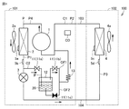
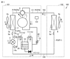
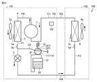
- FIG. It is a refrigerant circuit diagram of the refrigerating cycle apparatus which concerns on Embodiment 1.
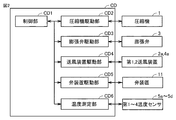
- FIG. It is a functional block diagram of the control apparatus of the refrigeration cycle apparatus which concerns on Embodiment 1.
- FIG. It is a refrigerant circuit diagram in the high load operation of the refrigeration cycle apparatus which concerns on Embodiment 1.
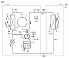
- FIG. It is a refrigerant circuit diagram in the refrigerant storage operation of the refrigerating cycle apparatus which concerns on Embodiment 1.
- FIG. It is a refrigerant circuit diagram in the refrigerant recovery operation of the refrigerating cycle apparatus which concerns on Embodiment 1.
- FIG. It is a flowchart which shows the refrigerant amount adjustment of the refrigerating cycle apparatus which concerns on Embodiment 1.
- FIG. 1 It is a graph which shows the relationship between the amount of a refrigerant of a refrigerating cycle apparatus which concerns on Embodiment 1 and a comparative example, and a coefficient of performance.
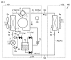
- It is a refrigerant circuit diagram of the modification of the refrigerating cycle apparatus which concerns on Embodiment 1.
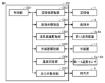
- FIG. It is a functional block diagram of the control apparatus of the modification of the refrigerating cycle apparatus which concerns on Embodiment 1.
- FIG. It is a refrigerant circuit diagram in the high load operation of the modification of the refrigerating cycle apparatus which concerns on Embodiment 1.
- FIG. It is a refrigerant circuit diagram in the refrigerant storage operation of the modification of the refrigerating cycle apparatus which concerns on Embodiment 1.
- FIG. It is a refrigerant circuit diagram in the refrigerant recovery operation of the modification of the refrigerating cycle apparatus which concerns on Embodiment 1.
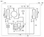
- FIG. It is a refrigerant circuit diagram of the refrigerating cycle apparatus which concerns on Embodiment 2.
- FIG. It is a refrigerant circuit diagram in the high load operation of the refrigeration cycle apparatus which concerns on Embodiment 2.
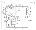
- FIG. It is a refrigerant circuit diagram in the refrigerant storage operation of the refrigerating cycle apparatus which concerns on Embodiment 2.
- FIG. It is a refrigerant circuit diagram in the refrigerant recovery operation of the refrigerating cycle apparatus which concerns on Embodiment 2.
- FIG. 2 It is a refrigerant circuit diagram of the modification of the refrigerating cycle apparatus which concerns on Embodiment 2.
- FIG. 2 It is a refrigerant circuit diagram in the high load operation of the modification of the refrigerating cycle apparatus which concerns on Embodiment 2.
- FIG. 2 It is a refrigerant circuit diagram in the refrigerant storage operation of the modification of the refrigerating cycle apparatus which concerns on Embodiment 2.
- FIG. It is a refrigerant circuit diagram in the refrigerant recovery operation of the modification of the refrigerating cycle apparatus which concerns on Embodiment 2.
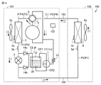
- FIG. It is a refrigerant circuit diagram of the refrigerating cycle apparatus which concerns on Embodiment 3.
- FIG. 3 It is a refrigerant circuit diagram of the refrigerating cycle apparatus which concerns on Embodiment 3.
- FIG. It is a refrigerant circuit diagram in the high load operation of the refrigeration cycle apparatus which concerns on Embodiment 3.
- FIG. It is a refrigerant circuit diagram in the refrigerant storage operation of the refrigerating cycle apparatus which concerns on Embodiment 3.
- FIG. It is a refrigerant circuit diagram in the refrigerant recovery operation of the refrigerating cycle apparatus which concerns on Embodiment 3.
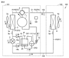
- FIG. It is a refrigerant circuit diagram of the modification of the refrigerating cycle apparatus which concerns on Embodiment 3.
- FIG. It is a refrigerant circuit diagram in the high load operation of the modification of the refrigerating cycle apparatus which concerns on Embodiment 3.
- FIG. 1 It is a refrigerant circuit diagram in the refrigerant storage operation of the modification of the refrigerating cycle apparatus which concerns on Embodiment 3.
- FIG. 1 It is a refrigerant circuit diagram in the refrigerant recovery operation of the modification of the refrigerating cycle apparatus which concerns on Embodiment 3.
- FIG. 1 It is a refrigerant circuit diagram in the refrigerant storage operation of the modification of the refrigerating cycle apparatus which concerns on Embodiment 3.
- Embodiment 1 The configuration of the refrigeration cycle apparatus 100 according to the first embodiment will be described with reference to FIG.
- the refrigeration cycle device 100 is, for example, an air conditioner and a refrigerator.
- an air conditioner will be described as an example of the refrigeration cycle device 100.
- the refrigerating cycle device 100 includes a refrigerant circuit C1, a refrigerant storage circuit C2, a control device CD, a first blower device 2a, a second blower device 4a, a first temperature sensor 5a, and a first. It includes two temperature sensors 5b, a third temperature sensor 5c, and a fourth temperature sensor 5d.
- the refrigerant circuit C1 includes a compressor 1, an outdoor heat exchanger (condenser) 2, an expansion valve 3, and an indoor heat exchanger (evaporator) 4.
- the refrigerant circuit C1 is configured so that the refrigerant flows in the order of the compressor 1, the outdoor heat exchanger (condenser) 2, the expansion valve 3, and the indoor heat exchanger (evaporator) 4.
- the refrigerant circuit C1 is configured to circulate the refrigerant. The refrigerant circulates in the refrigerant circuit C1 while changing the phase.
- the compressor 1, the outdoor heat exchanger (condenser) 2, the expansion valve 3, and the indoor heat exchanger (evaporator) 4 are connected by a pipe P.
- the pipe P has a first pipe portion P1, a second pipe portion P2, a third pipe portion P3, and a fourth pipe portion P4.
- the first pipe portion P1 connects the outdoor heat exchanger (condenser) 2 and the expansion valve 3.
- the second pipe portion P2 connects the indoor heat exchanger (evaporator) 4 and the compressor 1.
- the third pipe portion P3 connects the expansion valve 3 and the indoor heat exchanger (evaporator) 4.
- the fourth pipe portion P4 connects the compressor 1 and the outdoor heat exchanger (condenser) 2.
- the compressor 1, the outdoor heat exchanger 2, the first blower 2a, the expansion valve 3, the first temperature sensor 5a, the second temperature sensor 5b, and the control device CD are housed in the outdoor unit 101.
- the indoor heat exchanger 4, the second blower 4a, the third temperature sensor 5c, and the fourth temperature sensor 5d are housed in the indoor unit 102.
- the outdoor unit 101 and the indoor unit 102 are connected by a gas pipe 103 and a liquid pipe 104. A part of the pipe P constitutes the gas pipe 103 and the liquid pipe 104.
- the control device CD is configured to control each device of the refrigeration cycle device 100 by performing calculations, instructions, and the like.
- the control device CD is electrically connected to a compressor 1, an expansion valve 3, a first blower device 2a, a second blower device 4a, and the like, and is configured to control the operation thereof. Further, the control device CD is electrically connected to each of the first temperature sensor 5a, the second temperature sensor 5b, the third temperature sensor 5c, and the fourth temperature sensor 5d, and is based on the signals detected by these. It is configured to control each device and the like.
- the control device CD is composed of, for example, a microcomputer.
- the control device CD includes a CPU (Central Processing Unit), a RAM (Random Access Memory), a ROM (Read Only Memory), and the like.
- the control program is stored in the ROM.
- the compressor 1 is configured to compress the refrigerant.
- the compressor 1 is configured to compress and discharge the sucked refrigerant.
- the compressor 1 may be configured to have a variable capacity.
- the compressor 1 may be configured to change its capacity by adjusting the rotation speed of the compressor 1 based on an instruction from the control device CD.
- the outdoor heat exchanger 2 is configured to exchange heat between the refrigerant flowing inside the outdoor heat exchanger 2 and the air flowing outside the outdoor heat exchanger 2.
- the outdoor heat exchanger 2 is configured to function as a condenser.
- the outdoor heat exchanger 2 is a fin-and-tube heat exchanger having a plurality of fins and a heat transfer tube penetrating the plurality of fins.
- the expansion valve 3 is configured to reduce the pressure by expanding the refrigerant condensed by the outdoor heat exchanger 2.
- the expansion valve 3 is, for example, a solenoid valve. This solenoid valve is configured so that the flow rate of the refrigerant can be adjusted based on the instruction from the control device CD.
- the indoor heat exchanger 4 is configured to exchange heat between the refrigerant flowing inside the indoor heat exchanger 4 and the air flowing outside the indoor heat exchanger 4.
- the indoor heat exchanger 4 is configured to function as an evaporator.
- the indoor heat exchanger 4 is a fin-and-tube heat exchanger having a plurality of fins and a heat transfer tube penetrating the plurality of fins.
- the first blower device 2a is configured to blow outdoor air to the outdoor heat exchanger 2. That is, the first blower device 2a is configured to supply air to the outdoor heat exchanger 2.
- the first blower device 2a adjusts the amount of air flowing around the outdoor heat exchanger 2 by adjusting the rotation speed of the fan of the first blower device 2a based on the instruction from the control device CD, thereby adjusting the refrigerant. It may be configured to adjust the amount of heat exchange between air and air.
- the second blower 4a is configured to blow indoor air to the indoor heat exchanger 4. That is, the second blower 4a is configured to supply air to the indoor heat exchanger 4.
- the second blower 4a adjusts the amount of air flowing around the indoor heat exchanger 4 by adjusting the rotation speed of the fan of the second blower 4a based on the instruction from the control device CD, thereby adjusting the refrigerant. It may be configured to adjust the amount of heat exchange between air and air.
- the first temperature sensor 5a is connected to the outdoor heat exchanger 2.
- the first temperature sensor 5a is configured to detect the temperature of the refrigerant flowing through the outdoor heat exchanger 2.
- the second temperature sensor 5b is connected to the first pipe portion P1.
- the second temperature sensor 5b is configured to detect the temperature of the refrigerant flowing out of the outdoor heat exchanger 2.
- the third temperature sensor 5c is connected to the indoor heat exchanger 4.
- the third temperature sensor 5c is configured to detect the temperature of the refrigerant flowing through the indoor heat exchanger 4.
- the fourth temperature sensor 5d is connected to the third pipe portion P3.
- the fourth temperature sensor 5d is configured to detect the temperature of the refrigerant flowing into the indoor heat exchanger 4.
- the refrigerant storage circuit C2 is configured to be able to store the refrigerant.
- the refrigerant storage circuit C2 is connected to the refrigerant circuit C1.
- the refrigerant storage circuit C2 includes a valve device 11, a storage container 12, and an expander 13. In the refrigerant storage circuit C2, the valve device 11, the storage container 12, and the expander 13 are connected by a pipe P.
- the valve device 11 is arranged between the first pipe portion P1 and the expander 13.
- the valve device 11 is configured to be able to open and close the refrigerant storage circuit C2.
- the valve device 11 is configured to be able to open and close the refrigerant storage circuit C2 based on an instruction from the control device CD.
- the valve device 11 is, for example, a solenoid valve. This solenoid valve is configured so that the flow rate of the refrigerant can be adjusted based on the instruction from the control device CD.
- the storage container 12 is configured to store the refrigerant. Further, the storage container 12 is configured to discharge the refrigerant. That is, the storage container 12 is configured to temporarily store the refrigerant and then discharge the refrigerant. Therefore, the storage container 12 is configured to take in and out the refrigerant.
- the expander 13 is arranged between the storage container 12 and the second pipe portion P2.
- the inflator 13 is configured to reduce the pressure by expanding the refrigerant flowing out of the storage container 12.
- the inflator 13 is, for example, a capillary tube. This solenoid valve is configured so that the flow rate of the refrigerant can be adjusted based on the instruction from the control device CD.
- the refrigerant storage circuit has an inflow path IF, a first outflow path OF1, and a second outflow path OF2.
- the inflow path IF is configured to allow the refrigerant to flow into the storage container 12.
- the inflow path IF is connected to the first pipe portion P1 and the storage container 12.
- the inflow port of the inflow path IF is arranged inside the storage container 12.
- the inflow port of the inflow path IF is arranged below the outflow port of the first outflow path OF1 and above the outflow port of the second outflow path OF2.
- the first outflow passage OF1 is configured to allow the gas-state refrigerant to flow out from the storage container 12.
- the first outflow channel OF1 is connected to the storage container 12 and the inflator 13.
- the discharge port of the first outflow channel OF1 is arranged inside the storage container 12.
- the discharge port of the first outflow passage OF1 is arranged above the inflow port of the inflow passage IF and the second outflow passage OF2.
- the second outflow passage OF2 is configured to allow the liquid refrigerant to flow out from the storage container 12.
- the second outflow channel OF2 is connected to the storage container 12 and the inflator 13.
- the discharge port of the second outflow channel OF2 is arranged inside the storage container 12.
- the discharge port of the second outflow passage OF2 is arranged below the inflow passage IF and the first outflow passage OF1.
- valve device 11 When the refrigerant is stored in the storage container 12, the valve device 11 is configured to open the inflow path IF and the first outflow path OF1 and close the second outflow path OF2. When the refrigerant is recovered from the storage container 12, the valve device 11 is configured to close the first outflow passage OF1 and open the second outflow passage OF2.
- the valve device 11 has a first valve 11a, a second valve 11b, and a third valve 11c.
- the first valve 11a, the second valve 11b, and the third valve 11c are configured to be independently controllable.
- the first valve 11a is configured to be able to open and close the inflow path IF.
- the first valve 11a is connected to the first pipe portion P1 and the storage container 12 by a pipe P.
- the second valve 11b is configured to be able to open and close the first outflow path OF1.
- the second valve 11b is connected to the storage container 12 and the inflator 13 by a pipe P.
- the third valve 11c is configured to be able to open and close the second outflow path OF2.
- the third valve 11c is connected to the storage container 12 and the inflator 13 by a pipe P.
- the first valve 11a opens the inflow path IF
- the second valve 11b opens the first outflow path OF1
- the third valve 11c closes the second outflow path OF2. It is configured.
- the second valve 11b is configured to close the first outflow passage OF1
- the third valve 11c is configured to open the second outflow passage OF2.
- the control device CD includes a control unit CD1, a compressor drive unit CD2, an expansion valve drive unit CD3, a blower device drive unit CD4, a valve device drive unit CD5, and a temperature measurement unit CD6.
- the control unit CD1 is configured to control the compressor drive unit CD2, the expansion valve drive unit CD3, the blower device drive unit CD4, the valve device drive unit CD5, and the temperature measurement unit CD6.
- the compressor drive unit CD2 is configured to drive the compressor 1 based on an instruction from the control unit CD1. For example, the compressor drive unit CD2 is configured to control the rotation speed of the motor of the compressor 1 by controlling the frequency of the alternating current flowing through the motor of the compressor 1.
- the expansion valve drive unit CD3 is configured to drive the expansion valve 3 based on an instruction from the control unit CD1.
- the expansion valve drive unit CD3 is configured to control the valve opening degree of the expansion valve 3 by controlling a drive source such as a motor of the expansion valve 3.
- the blower device drive unit CD4 is configured to drive the first blower device 2a and the second blower device 4a based on the instruction from the control unit CD1.
- the blower drive unit CD4 controls the rotation speed of the fans of the first blower device 2a and the second blower device 4a by controlling the drive sources such as the motors of the first blower device 2a and the second blower device 4a. It is configured as follows.
- the valve device drive unit CD5 is configured to drive the valve device 11 based on an instruction from the control unit CD1.
- the valve device drive unit CD5 is configured to control the valve opening degree of the valve device 11 by controlling a drive source such as a motor of the valve device 11.
- the temperature measuring unit CD6 is configured to measure the temperature of the refrigerant based on the signals from the first temperature sensor 5a to the fourth temperature sensor 5d and transmit the signal based on the temperature of the refrigerant to the control unit CD1.
- the operation of the refrigeration cycle device 100 according to the first embodiment will be described.
- the valve device 11 is painted black to indicate the closed state.
- the valve device 11 filled in black shows the closed state.
- the refrigerant flowing into the compressor 1 is compressed by the compressor 1 to become a high-temperature and high-pressure gas refrigerant, and is discharged from the compressor 1.
- the high-temperature and high-pressure gas refrigerant flows into the outdoor heat exchanger 2, is condensed by the outdoor heat exchanger 2 to become a liquid refrigerant, and flows out from the outdoor heat exchanger 2.
- This liquid refrigerant flows into the expansion valve 3, is depressurized by the expansion valve 3, becomes a low-pressure gas-liquid two-phase refrigerant, and flows out from the expansion valve 3.
- This low-pressure gas-liquid two-phase refrigerant flows into the indoor heat exchanger 4, is evaporated by the indoor heat exchanger 4, becomes a gas refrigerant, and flows out from the indoor heat exchanger 4.
- This gas refrigerant flows into the compressor 1. In this way, the refrigerant circulates in the refrigerant circuit C1.
- the valve device 11 closes the refrigerant storage circuit C2. Specifically, all of the first valve 11a, the second valve 11b, and the third valve 11c close the refrigerant storage circuit C2. Therefore, the liquid refrigerant flowing out of the outdoor heat exchanger 2 does not flow into the storage container 12 of the refrigerant storage circuit C2. Further, the refrigerant 20 stored in the storage container 12 does not flow into the refrigerant circuit C1.
- a low load operation which is an operation in which the rotation speed of the compressor 1 is low
- a high load operation which is an operation in which the rotation speed of the compressor 1 is high
- the amount of refrigerant that maximizes the performance of the refrigeration cycle is smaller in high load operation than in low load operation. Therefore, in the low load operation, the amount of the refrigerant flowing through the refrigerant circuit C1 is larger than in the high load operation, and the amount of the refrigerant 20 stored in the storage container 12 of the refrigerant storage circuit C2 is smaller.
- the refrigerant circulates in the refrigerant circuit C1 as in the low load operation. Further, the valve device 11 closes the refrigerant storage circuit C2 as in the low load operation.
- the amount of refrigerant flowing through the refrigerant circuit C1 is smaller than during low load operation, and the amount of refrigerant 20 stored in the storage container 12 of the refrigerant storage circuit C2 is larger.
- the valve device 11 opens the inflow path IF and the first outflow path OF1 and closes the second outflow path OF2.
- the first valve 11a opens the inflow path IF
- the second valve 11b opens the first outflow path OF1
- the third valve 11c opens the second outflow path OF2. Close.
- a part of the liquid refrigerant flowing out of the outdoor heat exchanger 2 flows into the storage container 12 of the refrigerant storage circuit C2 from the inflow path IF and is stored in the storage container 12.
- the gas refrigerant flows out from the first outflow path OF1.
- the liquid refrigerant is stored in the storage container 12.
- valve device 11 closes the first outflow passage OF1 and opens the second outflow passage OF2. Further, the valve device 11 opens the inflow path IF. Specifically, when the refrigerant is recovered from the storage container 12, the second valve 11b closes the first outflow passage OF1 and the third valve 11c opens the second outflow passage OF2. Further, the first valve 11a opens the inflow path IF.
- This refrigerant is recovered in the refrigerant circuit C1.
- the liquid refrigerant stored in the storage container 12 is recovered.
- the amount of the liquid refrigerant flowing out is larger than the amount of the liquid refrigerant flowing into the storage container 12.
- the amount of liquid refrigerant flowing into the storage container 12 may be reduced, for example, by stopping the rotation of the fan of the first blower device 2a.
- the refrigerant amount adjustment in the refrigeration cycle apparatus 100 according to the first embodiment will be described.
- the refrigerant amount is adjusted based on the degree of supercooling (subcooling).
- the subcool (SC) is calculated (step S2).
- the subcool (SC) is calculated by the control unit CD1 from the difference between the temperature of the refrigerant detected by the first temperature sensor 5a and the temperature of the refrigerant detected by the second temperature sensor 5b.
- the subcool (SC) is calculated from the difference between the temperature of the refrigerant detected by the third temperature sensor 5c and the temperature of the refrigerant detected by the fourth temperature sensor 5d.
- the target subcool (SC) is calculated (step S3).
- the target subcool (SC) is calculated by the control unit CD1 from the rotation speed of the compressor 1 and the outside air temperature.
- control unit CD1 determines whether or not the subcool (SC) is smaller than the target SC- ⁇ in which the target subcool (SC) has a margin to the low temperature side (step S4).
- the refrigerant recovery operation is performed (step S5). If the subcool (SC) is smaller than the target SC- ⁇ , it is judged that the amount of refrigerant is insufficient.
- the control unit CD1 determines whether or not the subcool (SC) is larger than the target SC + ⁇ in which the target subcool (SC) has a margin to the high temperature side. It is determined (step S6). When the subcool (SC) is larger than the target SC + ⁇ , the refrigerant storage operation is carried out (step S7). If the subcool (SC) is larger than the target SC + ⁇ , it is determined that the amount of refrigerant is excessive.
- the control unit CD1 determines whether the subcool (SC) is larger than the target SC- ⁇ and smaller than the target SC + ⁇ (step S8). If the subcool (SC) is larger than the target SC- ⁇ and not smaller than the target SC + ⁇ , the subcool (SC) is calculated again. When the subcool (SC) is larger than the target SC- ⁇ and smaller than the target SC + ⁇ , the refrigerant amount adjustment is completed (step S9).
- the coefficient of performance (COP) can be improved by making the amount of the refrigerant different in each of the low load operation and the high load operation.
- the coefficient of performance (COP) it is difficult to improve the coefficient of performance (COP) in both the low load operation and the high load operation because the amount of the refrigerant is constant in both the low load operation and the high load operation.
- the valve device 11 is configured to be able to open and close the refrigerant storage circuit C2 having the storage container 12. Therefore, when the valve device 11 opens and closes the refrigerant storage circuit C2, the refrigerant is stored in the storage container 12 according to the operating state, so that the performance of the refrigeration cycle can be improved.
- the compressor 1, the outdoor heat exchanger 2, the expansion valve 3, and the indoor heat exchanger 4 are connected by a pipe P. Therefore, since there is only one expansion valve 3, the controllability of the expansion valve 3 can be improved.
- the first valve 11a opens the inflow path IF
- the second valve 11b opens the first outflow path OF1
- the third valve 11c closes the second outflow path OF2.
- the second valve 11b closes the first outflow passage OF1
- the third valve 11c opens the second outflow passage OF2. Therefore, the amount of refrigerant flowing through the refrigerant circuit C1 can be adjusted.
- the modified example of the refrigerating cycle device 100 according to the first embodiment has the same configuration, operation, and operation and effect as the refrigerating cycle device 100 according to the first embodiment.
- the refrigerant circuit C1 has a four-way valve 6.
- the refrigerant circuit C1 converts the refrigerant into a compressor 1, a four-way valve 6, a condenser (outdoor heat exchanger 2 or indoor heat exchanger 4), an expansion valve 3, and an evaporator (indoor heat exchanger 4 or outdoor heat exchanger 2).
- the four-way valve 6 is configured to flow in this order.
- the refrigerant storage circuit C2 has a first check valve 14a and a second check valve 14b.
- the outdoor heat exchanger 2 is configured to function as a condenser in the cooling operation and as an evaporator in the heating operation.
- the indoor heat exchanger 4 is configured to function as an evaporator in the cooling operation and as a condenser in the heating operation.
- the four-way valve 6 is connected to the compressor 1, the outdoor heat exchanger 2, and the indoor heat exchanger 4.
- the four-way valve 6 is configured to be able to switch the flow of the refrigerant so that the refrigerant flows from the compressor 1 to the outdoor heat exchanger 2 in the cooling operation and the refrigerant flows from the compressor 1 to the indoor heat exchanger 4 in the heating operation. There is.
- the first check valve 14a and the second check valve 14b are arranged in parallel with the valve device 11.
- the first check valve 14a is arranged in the pipe P branched between the outdoor heat exchanger 2 and the expansion valve 3.
- the second check valve 14b is arranged in the pipe P branched between the indoor heat exchanger 4 and the expansion valve 3.
- Each of the first check valve 14a and the second check valve 14b is configured to allow the refrigerant to flow toward the valve device 11 and not to flow to the side opposite to the valve device 11.
- the control device CD has a four-way valve drive unit CD7.
- the four-way valve drive unit CD7 is configured to drive the four-way valve 6 based on an instruction from the control unit CD1.
- the four-way valve drive unit CD7 is configured to control switching of the four-way valve 6 by controlling a drive source such as a motor of the four-way valve 6.
- the solid line arrow in the figure indicates the flow of the refrigerant in the cooling operation
- the broken line arrow in the figure indicates the flow of the refrigerant in the heating operation.
- the refrigerant circulates in the refrigerant circuit C1 in the order of the compressor 1, the four-way valve 6, the outdoor heat exchanger (condenser) 2, the expansion valve 3, the indoor heat exchanger (evaporator) 4, and the four-way valve 6. ..
- the refrigerant circulates in the refrigerant circuit C1 as in the low load operation.
- the operation of storing the refrigerant in the storage container 12 (refrigerant storage operation) will be described with reference to FIG.
- a part of the liquid refrigerant flowing out of the outdoor heat exchanger 2 flows into the refrigerant storage circuit C2 from the first pipe portion P1.
- the liquid refrigerant that has flowed into the refrigerant storage circuit C2 passes through the first check valve 14a, flows into the storage container 12 via the first valve 11a, and is stored in the storage container 12.
- the gas refrigerant flows out from the first outflow path OF1. In this way, in the refrigerant storage operation, the liquid refrigerant is stored in the storage container 12.
- the operation of recovering the refrigerant stored in the storage container 12 of the refrigerant storage circuit C2 (refrigerant recovery operation) will be described.
- a part of the liquid refrigerant flowing out of the outdoor heat exchanger 2 flows into the refrigerant storage circuit C2 from the first pipe portion P1.
- the liquid refrigerant that has flowed into the refrigerant storage circuit C2 passes through the first check valve 14a, flows into the storage container 12 via the first valve 11a, and flows out from the second outflow path OF2. In this way, in the refrigerant recovery operation, the liquid refrigerant stored in the storage container 12 is recovered.
- the high-temperature and high-pressure gas refrigerant discharged from the compressor 1 flows into the indoor heat exchanger (condenser) 4 and is condensed by the indoor heat exchanger 4 to become a liquid refrigerant, which becomes an indoor heat exchanger.
- This liquid refrigerant flows into the expansion valve 3, is depressurized by the expansion valve 3, becomes a low-pressure gas-liquid two-phase refrigerant, and flows out from the expansion valve 3.
- This low-pressure gas-liquid two-phase refrigerant flows into the outdoor heat exchanger (evaporator) 2, is evaporated by the outdoor heat exchanger 2 to become a gas refrigerant, and flows out from the outdoor heat exchanger 2.
- This gas refrigerant flows into the compressor 1 via the four-way valve 6.
- the refrigerant circulates in the refrigerant circuit C1. That is, in the heating operation, the refrigerant passes through the refrigerant circuit C1 in the order of the compressor 1, the four-way valve 6, the indoor heat exchanger (condenser) 4, the expansion valve 3, the outdoor heat exchanger (evaporator) 2, and the four-way valve 6. Circulate.
- the refrigerant circulates in the refrigerant circuit C1 as in the low load operation.
- a part of the liquid refrigerant flowing out from the indoor heat exchanger (evaporator) 4 is a part of the indoor heat exchanger (evaporator).
- ) 4 flows into the refrigerant storage circuit C2 from the first pipe portion P1 connecting the expansion valve 3.
- the liquid refrigerant that has flowed into the refrigerant storage circuit C2 passes through the second check valve 14b, flows into the storage container 12 via the first valve 11a, and is stored in the storage container 12.
- the gas refrigerant flows out from the first outflow path OF1. In this way, in the refrigerant storage operation, the liquid refrigerant is stored in the storage container 12.
- the four-way valve 6 causes the refrigerant to flow from the compressor 1 to the outdoor heat exchanger 2 in the cooling operation, and the indoor heat exchange from the compressor 1 in the heating operation.
- the flow of the refrigerant can be switched so that the refrigerant flows through the vessel 4. Therefore, the refrigerant can be stored in the storage container 12 in both the cooling operation and the heating operation. Therefore, in both cooling operation and heating operation.
- the storage container 12 can improve the performance of the refrigeration cycle and the controllability of the expansion valve 3.
- the first check valve 14a or the second check valve 14b causes the heat to flow out from the outdoor heat exchanger 2 or the indoor heat exchanger 4 that functions as a condenser. It is possible to prevent the liquid refrigerant from flowing into the compressor 1 without being depressurized by the expansion valve 3.
- the refrigerating cycle apparatus 100 according to the second embodiment has the same configuration, operation, and effect as the refrigerating cycle apparatus 100 according to the first embodiment.
- the valve device 11 is a three-way valve 11d.
- the three-way valve 11d is arranged between the first outflow path OF1, the second outflow path OF2, and the expander 13.
- the three-way valve 11d is configured to be able to switch between flowing the refrigerant from the first outflow path OF1 to the expander 13 and flowing the refrigerant from the second outflow path OF2 to the expander 13.
- the three-way valve 11d When the refrigerant is stored in the storage container 12, the three-way valve 11d is configured to connect the first outflow path OF1 and the expander 13. When the refrigerant is recovered from the storage container 12, the three-way valve 11d is configured to connect the second outflow path OF2 and the expander 13.
- the refrigerant circulates in the refrigerant circuit C1 in the order of the compressor 1, the outdoor heat exchanger (condenser) 2, the expansion valve 3, and the indoor heat exchanger (evaporator) 4.
- the valve device 11 closes the refrigerant storage circuit C2. Specifically, the three-way valve 11d closes the refrigerant storage circuit C2. Therefore, the refrigerant stored in the storage container 12 does not flow into the refrigerant circuit C1.
- the operation of the refrigeration cycle device 100 according to the second embodiment during the high load operation in the cooling operation will be described.
- the refrigerant circulates in the refrigerant circuit C1 as in the low load operation.
- the three-way valve 11d closes the refrigerant storage circuit C2 as in the low load operation.
- the amount of refrigerant flowing through the refrigerant circuit C1 is smaller than during low load operation, and the amount of refrigerant 20 stored in the storage container 12 of the refrigerant storage circuit C2 is larger.
- the operation of storing the refrigerant in the storage container 12 (refrigerant storage operation) will be described with reference to FIG.
- the three-way valve 11d connects the first outflow path OF1 and the expander 13.
- a part of the liquid refrigerant flowing out of the outdoor heat exchanger 2 flows into the storage container 12 of the refrigerant storage circuit C2 from the inflow path IF and is stored in the storage container 12.
- the gas refrigerant flows out from the first outflow path OF1 to the expander 13. In this way, in the refrigerant storage operation, the liquid refrigerant is stored in the storage container 12.
- the refrigeration cycle device 100 when the refrigerant is stored in the storage container 12, the three-way valve 11d connects the first outflow passage OF1 and the expander 13.
- the three-way valve 11d connects the second outflow path OF2 and the expander 13. Therefore, the refrigerant storage circuit C2 can be opened and closed by one three-way valve 11d. Therefore, the number of drive circuits for driving the valves can be reduced as compared with the case where the valve device 11 has three valves. Therefore, the cost of the refrigeration cycle device 100 can be reduced.
- the modified example of the refrigerating cycle device 100 according to the second embodiment has the same configuration, operation, and effect as the refrigerating cycle device 100 according to the second embodiment.
- the refrigerant circuit C1 has a four-way valve 6.
- the refrigerant circuit C1 converts the refrigerant into a compressor 1, a four-way valve 6, a condenser (outdoor heat exchanger 2 or indoor heat exchanger 4), an expansion valve 3, and an evaporator (indoor heat exchanger 4 or outdoor heat exchanger 2).
- the four-way valve 6 is configured to flow in this order.
- the refrigerant storage circuit C2 has a first check valve 14a and a second check valve 14b.
- the solid line arrow in the figure indicates the flow of the refrigerant in the cooling operation
- the broken line arrow in the figure indicates the flow of the refrigerant in the heating operation.
- the cooling operation and the heating operation can be selectively performed.
- the refrigerant circulates in the refrigerant circuit C1 in the order of the compressor 1, the four-way valve 6, the outdoor heat exchanger (condenser) 2, the expansion valve 3, the indoor heat exchanger (evaporator) 4, and the four-way valve 6. ..
- the refrigerant circulates in the refrigerant circuit C1 as in the low load operation.
- the operation of storing the refrigerant in the storage container 12 (refrigerant storage operation) will be described with reference to FIG.
- a part of the liquid refrigerant flowing out of the outdoor heat exchanger 2 flows into the refrigerant storage circuit C2 from the first pipe portion P1.
- the liquid refrigerant that has flowed into the refrigerant storage circuit C2 passes through the first check valve 14a, flows into the storage container 12, and is stored in the storage container 12.
- the gas refrigerant flows out from the first outflow path OF1. In this way, in the refrigerant storage operation, the liquid refrigerant is stored in the storage container 12.
- the operation of recovering the refrigerant stored in the storage container 12 of the refrigerant storage circuit C2 (refrigerant recovery operation) will be described.
- a part of the liquid refrigerant flowing out of the outdoor heat exchanger 2 flows into the refrigerant storage circuit C2 from the first pipe portion P1.
- the liquid refrigerant that has flowed into the refrigerant storage circuit C2 passes through the first check valve 14a, flows into the storage container 12, and flows out from the second outflow path OF2. In this way, in the refrigerant recovery operation, the liquid refrigerant stored in the storage container 12 is recovered.
- the refrigerant circulates in the refrigerant circuit C1 in the order of the compressor 1, the four-way valve 6, the indoor heat exchanger (condenser) 4, the expansion valve 3, the outdoor heat exchanger (evaporator) 2, and the four-way valve 6. ..
- the refrigerant circulates in the refrigerant circuit C1 as in the low load operation.
- a part of the liquid refrigerant flowing out from the indoor heat exchanger (evaporator) 4 is a part of the indoor heat exchanger (evaporator).
- ) 4 flows into the refrigerant storage circuit C2 from the first pipe portion P1 connecting the expansion valve 3.
- the liquid refrigerant that has flowed into the refrigerant storage circuit C2 passes through the second check valve 14b, flows into the storage container 12, and is stored in the storage container 12.
- the gas refrigerant flows out from the first outflow path OF1. In this way, in the refrigerant storage operation, the liquid refrigerant is stored in the storage container 12.
- the four-way valve 6 causes the refrigerant to flow from the compressor 1 to the outdoor heat exchanger 2 in the cooling operation, and the indoor heat exchange from the compressor 1 in the heating operation.
- the flow of the refrigerant can be switched so that the refrigerant flows through the vessel 4. Therefore, the refrigerant can be stored in the storage container 12 in both the cooling operation and the heating operation. Therefore, in both cooling operation and heating operation.
- the storage container 12 can improve the performance of the refrigeration cycle and the controllability of the expansion valve 3.
- the refrigerating cycle apparatus 100 according to the third embodiment has the same configuration, operation, and effect as the refrigerating cycle apparatus 100 according to the first embodiment.
- the valve device 11 is a five-way valve 11e.
- the five-way valve 11e is arranged between the first pipe portion P1, the storage container 12, and the expander 13.
- the five-way valve 11e is configured to be able to switch between flowing the refrigerant from the first pipe portion P1 to the storage container 12 and flowing the refrigerant from the storage container 12 to the expander 13.
- the five-way valve 11e constitutes a part of the inflow path IF, the first outflow path OF1, and the second outflow path OF2.
- the five-way valve 11e connects the first pipe portion P1 and the storage container 12 so as to form the inflow path IF, and stores the refrigerant so as to form the first outflow path OF1. It is configured to connect the container 12 and the inflator 13.
- the five-way valve 11e is configured to connect the storage container 12 and the expander 13 so as to form the second outflow path OF2.
- the refrigerant circulates in the refrigerant circuit C1 in the order of the compressor 1, the outdoor heat exchanger (condenser) 2, the expansion valve 3, and the indoor heat exchanger (evaporator) 4.
- the valve device 11 closes the refrigerant storage circuit C2. Specifically, the five-way valve 11e closes the refrigerant storage circuit C2. Therefore, the refrigerant stored in the storage container 12 does not flow into the refrigerant circuit C1.
- the operation of the refrigeration cycle device 100 according to the third embodiment during the high load operation in the cooling operation will be described.
- the refrigerant circulates in the refrigerant circuit C1 as in the low load operation.
- the five-way valve 11e closes the refrigerant storage circuit C2 as in the low load operation.
- the amount of refrigerant flowing through the refrigerant circuit C1 is smaller than during low load operation, and the amount of refrigerant 20 stored in the storage container 12 of the refrigerant storage circuit C2 is larger.
- the operation of storing the refrigerant in the storage container 12 (refrigerant storage operation) will be described with reference to FIG. 23.
- the five-way valve 11e connects the first pipe portion P1 and the storage container 12 so as to form the inflow path IF, and stores the refrigerant so as to form the first outflow path OF1.
- the container 12 and the inflator 13 are connected.
- a part of the liquid refrigerant flowing out of the outdoor heat exchanger 2 flows into the storage container 12 from the inflow path IF and is stored in the storage container 12.
- the gas refrigerant flows out from the first outflow path OF1 to the expander 13. In this way, in the refrigerant storage operation, the liquid refrigerant is stored in the storage container 12.
- the operation of recovering the refrigerant stored in the storage container 12 of the refrigerant storage circuit C2 (refrigerant recovery operation) will be described.
- the five-way valve 11e is configured to connect the storage container 12 and the expander 13 so as to form the second outflow path OF2.
- the liquid refrigerant stored in the storage container 12 flows out from the second outflow passage OF2 to the expander 13. In this way, in the refrigerant recovery operation, the liquid refrigerant stored in the storage container 12 is recovered.
- the refrigerating cycle apparatus 100 when the refrigerant is stored in the storage container 12, the five-way valve 11e holds the first pipe portion P1 and the storage container 12 so as to form an inflow path IF.
- the storage container 12 and the inflator 13 are connected so as to be connected and to form the first outflow path OF1.
- the five-way valve 11e connects the storage container 12 and the expander 13 so as to form the second outflow path OF2. Therefore, the refrigerant storage circuit C2 can be opened and closed by one five-way valve 11e. Therefore, the number of drive circuits for driving the valves can be reduced as compared with the case where the valve device 11 has three valves. Therefore, the cost can be reduced.
- the modified example of the refrigerating cycle device 100 according to the third embodiment has the same configuration, operation, and effect as the refrigerating cycle device 100 according to the third embodiment.
- the refrigerant circuit C1 has a four-way valve 6.
- the refrigerant circuit C1 converts the refrigerant into a compressor 1, a four-way valve 6, a condenser (outdoor heat exchanger 2 or indoor heat exchanger 4), an expansion valve 3, and an evaporator (indoor heat exchanger 4 or outdoor heat exchanger 2).
- the four-way valve 6 is configured to flow in this order.
- the refrigerant storage circuit C2 has a first check valve 14a and a second check valve 14b.
- the solid line arrow in the figure indicates the flow of the refrigerant in the cooling operation
- the broken line arrow in the figure indicates the flow of the refrigerant in the heating operation.
- the cooling operation and the heating operation can be selectively performed.
- the refrigerant circulates in the refrigerant circuit C1 in the order of the compressor 1, the four-way valve 6, the outdoor heat exchanger (condenser) 2, the expansion valve 3, the indoor heat exchanger (evaporator) 4, and the four-way valve 6. ..
- the refrigerant circulates in the refrigerant circuit C1 as in the low load operation.
- the operation of storing the refrigerant in the storage container 12 (refrigerant storage operation) will be described with reference to FIG. 27.
- a part of the liquid refrigerant flowing out of the outdoor heat exchanger 2 flows into the refrigerant storage circuit C2 from the first pipe portion P1.
- the liquid refrigerant that has flowed into the refrigerant storage circuit C2 passes through the first check valve 14a, flows into the storage container 12, and is stored in the storage container 12.
- the gas refrigerant flows out from the first outflow path OF1. In this way, in the refrigerant storage operation, the liquid refrigerant is stored in the storage container 12.
- the operation of recovering the refrigerant stored in the storage container 12 of the refrigerant storage circuit C2 (refrigerant recovery operation) will be described.
- a part of the liquid refrigerant flowing out of the outdoor heat exchanger 2 flows into the refrigerant storage circuit C2 from the first pipe portion P1.
- the liquid refrigerant that has flowed into the refrigerant storage circuit C2 passes through the first check valve 14a, flows into the storage container 12, and flows out from the second outflow path OF2. In this way, in the refrigerant recovery operation, the liquid refrigerant stored in the storage container 12 is recovered.
- the refrigerant circulates in the refrigerant circuit C1 in the order of the compressor 1, the four-way valve 6, the indoor heat exchanger (condenser) 4, the expansion valve 3, the outdoor heat exchanger (evaporator) 2, and the four-way valve 6. ..
- the refrigerant circulates in the refrigerant circuit C1 as in the low load operation.
- a part of the liquid refrigerant flowing out from the indoor heat exchanger (evaporator) 4 is a part of the indoor heat exchanger (evaporator).
- ) 4 flows into the refrigerant storage circuit C2 from the first pipe portion P1 connecting the expansion valve 3.
- the liquid refrigerant that has flowed into the refrigerant storage circuit C2 passes through the second check valve 14b, flows into the storage container 12, and is stored in the storage container 12.
- the gas refrigerant flows out from the first outflow path OF1. In this way, in the refrigerant storage operation, the liquid refrigerant is stored in the storage container 12.
- the four-way valve 6 causes the refrigerant to flow from the compressor 1 to the outdoor heat exchanger 2 in the cooling operation, and the indoor heat exchange from the compressor 1 in the heating operation.
- the flow of the refrigerant can be switched so that the refrigerant flows through the vessel 4. Therefore, the refrigerant can be stored in the storage container 12 in both the cooling operation and the heating operation. Therefore, in both cooling operation and heating operation.
- the storage container 12 can improve the performance of the refrigeration cycle and the controllability of the expansion valve 3.
Landscapes
- Engineering & Computer Science (AREA)
- Physics & Mathematics (AREA)
- Mechanical Engineering (AREA)
- Thermal Sciences (AREA)
- General Engineering & Computer Science (AREA)
- Fluid Mechanics (AREA)
- Compression-Type Refrigeration Machines With Reversible Cycles (AREA)
- Air Conditioning Control Device (AREA)
Priority Applications (4)
| Application Number | Priority Date | Filing Date | Title |
|---|---|---|---|
| US17/911,276 US20230131781A1 (en) | 2020-05-11 | 2020-05-11 | Refrigeration cycle apparatus |
| EP20935247.5A EP4151926A4 (en) | 2020-05-11 | 2020-05-11 | REFRIGERATION CIRCUIT DEVICE |
| JP2022522106A JP7407920B2 (ja) | 2020-05-11 | 2020-05-11 | 冷凍サイクル装置 |
| PCT/JP2020/018843 WO2021229647A1 (ja) | 2020-05-11 | 2020-05-11 | 冷凍サイクル装置 |
Applications Claiming Priority (1)
| Application Number | Priority Date | Filing Date | Title |
|---|---|---|---|
| PCT/JP2020/018843 WO2021229647A1 (ja) | 2020-05-11 | 2020-05-11 | 冷凍サイクル装置 |
Publications (1)
| Publication Number | Publication Date |
|---|---|
| WO2021229647A1 true WO2021229647A1 (ja) | 2021-11-18 |
Family
ID=78525436
Family Applications (1)
| Application Number | Title | Priority Date | Filing Date |
|---|---|---|---|
| PCT/JP2020/018843 Ceased WO2021229647A1 (ja) | 2020-05-11 | 2020-05-11 | 冷凍サイクル装置 |
Country Status (4)
| Country | Link |
|---|---|
| US (1) | US20230131781A1 (https=) |
| EP (1) | EP4151926A4 (https=) |
| JP (1) | JP7407920B2 (https=) |
| WO (1) | WO2021229647A1 (https=) |
Cited By (1)
| Publication number | Priority date | Publication date | Assignee | Title |
|---|---|---|---|---|
| WO2025069511A1 (ja) * | 2023-09-29 | 2025-04-03 | パナソニックIpマネジメント株式会社 | 冷凍システム |
Families Citing this family (1)
| Publication number | Priority date | Publication date | Assignee | Title |
|---|---|---|---|---|
| CN119665348A (zh) * | 2024-12-24 | 2025-03-21 | 珠海格力电器股份有限公司 | 冷媒循环系统及其控制方法、装置、电子设备及存储介质 |
Citations (4)
| Publication number | Priority date | Publication date | Assignee | Title |
|---|---|---|---|---|
| JPH10111047A (ja) | 1996-10-03 | 1998-04-28 | Hitachi Ltd | 空気調和機 |
| WO2008093718A1 (ja) * | 2007-01-31 | 2008-08-07 | Daikin Industries, Ltd. | 熱源ユニット及び冷凍装置 |
| JP2010127531A (ja) * | 2008-11-27 | 2010-06-10 | Mitsubishi Electric Corp | 冷凍空調装置 |
| JP2012207823A (ja) * | 2011-03-29 | 2012-10-25 | Fujitsu General Ltd | 冷凍サイクル装置 |
Family Cites Families (5)
| Publication number | Priority date | Publication date | Assignee | Title |
|---|---|---|---|---|
| JP2012077983A (ja) * | 2010-09-30 | 2012-04-19 | Daikin Industries Ltd | 冷凍回路 |
| CN104949402B (zh) * | 2014-03-28 | 2019-03-05 | 珠海格力电器股份有限公司 | 冷媒调节器、冷媒调节方法及空调器 |
| JP6621616B2 (ja) * | 2014-09-03 | 2019-12-18 | 三星電子株式会社Samsung Electronics Co.,Ltd. | 冷媒量検知装置 |
| DE102015223548A1 (de) * | 2015-11-27 | 2017-06-01 | Airbus Operations Gmbh | Flugzeugklimaanlage mit Umgebungsluftzufuhr und Verfahren zum Betreiben einer derartigen Flugzeugklimaanlage |
| JP6555293B2 (ja) * | 2017-03-31 | 2019-08-07 | ダイキン工業株式会社 | 冷凍装置の室内ユニット |
-
2020
- 2020-05-11 US US17/911,276 patent/US20230131781A1/en not_active Abandoned
- 2020-05-11 WO PCT/JP2020/018843 patent/WO2021229647A1/ja not_active Ceased
- 2020-05-11 JP JP2022522106A patent/JP7407920B2/ja active Active
- 2020-05-11 EP EP20935247.5A patent/EP4151926A4/en not_active Withdrawn
Patent Citations (4)
| Publication number | Priority date | Publication date | Assignee | Title |
|---|---|---|---|---|
| JPH10111047A (ja) | 1996-10-03 | 1998-04-28 | Hitachi Ltd | 空気調和機 |
| WO2008093718A1 (ja) * | 2007-01-31 | 2008-08-07 | Daikin Industries, Ltd. | 熱源ユニット及び冷凍装置 |
| JP2010127531A (ja) * | 2008-11-27 | 2010-06-10 | Mitsubishi Electric Corp | 冷凍空調装置 |
| JP2012207823A (ja) * | 2011-03-29 | 2012-10-25 | Fujitsu General Ltd | 冷凍サイクル装置 |
Non-Patent Citations (1)
| Title |
|---|
| See also references of EP4151926A4 |
Cited By (1)
| Publication number | Priority date | Publication date | Assignee | Title |
|---|---|---|---|---|
| WO2025069511A1 (ja) * | 2023-09-29 | 2025-04-03 | パナソニックIpマネジメント株式会社 | 冷凍システム |
Also Published As
| Publication number | Publication date |
|---|---|
| EP4151926A1 (en) | 2023-03-22 |
| EP4151926A4 (en) | 2023-06-14 |
| US20230131781A1 (en) | 2023-04-27 |
| JPWO2021229647A1 (https=) | 2021-11-18 |
| JP7407920B2 (ja) | 2024-01-04 |
Similar Documents
| Publication | Publication Date | Title |
|---|---|---|
| JP6479162B2 (ja) | 空気調和装置 | |
| US7155928B2 (en) | Refrigerating apparatus | |
| US6883346B2 (en) | Freezer | |
| JP4375171B2 (ja) | 冷凍装置 | |
| US20110174005A1 (en) | Refrigerating apparatus | |
| US7028502B2 (en) | Refrigeration equipment | |
| JP4725387B2 (ja) | 空気調和装置 | |
| JP2002081767A (ja) | 空気調和装置 | |
| WO2020208776A1 (ja) | 空気調和装置 | |
| JP2019086251A (ja) | マルチ型空気調和装置の制御装置、マルチ型空気調和装置、マルチ型空気調和装置の制御方法及びマルチ型空気調和装置の制御プログラム | |
| JP6964776B2 (ja) | 冷凍サイクル装置 | |
| JP7407920B2 (ja) | 冷凍サイクル装置 | |
| JP6984048B2 (ja) | 空気調和機 | |
| JP2002174463A (ja) | 冷凍装置 | |
| JP6835176B1 (ja) | 冷凍装置 | |
| JP3719296B2 (ja) | 冷凍サイクル装置 | |
| JP4601392B2 (ja) | 冷凍装置 | |
| JP4720641B2 (ja) | 冷凍装置 | |
| JP2020165545A (ja) | 空気調和装置 | |
| JP4887929B2 (ja) | 冷凍装置 | |
| JP2009115336A (ja) | 冷凍装置 | |
| JP7448848B2 (ja) | 空気調和装置 | |
| JP2019168130A (ja) | 空気調和機 | |
| WO2024127571A1 (ja) | 冷凍サイクル装置 | |
| JPH07294041A (ja) | 冷凍装置 |
Legal Events
| Date | Code | Title | Description |
|---|---|---|---|
| 121 | Ep: the epo has been informed by wipo that ep was designated in this application |
Ref document number: 20935247 Country of ref document: EP Kind code of ref document: A1 |
|
| ENP | Entry into the national phase |
Ref document number: 2022522106 Country of ref document: JP Kind code of ref document: A |
|
| NENP | Non-entry into the national phase |
Ref country code: DE |
|
| ENP | Entry into the national phase |
Ref document number: 2020935247 Country of ref document: EP Effective date: 20221212 |