WO2021225121A1 - スプリングコネクタ - Google Patents
スプリングコネクタ Download PDFInfo
- Publication number
- WO2021225121A1 WO2021225121A1 PCT/JP2021/017237 JP2021017237W WO2021225121A1 WO 2021225121 A1 WO2021225121 A1 WO 2021225121A1 JP 2021017237 W JP2021017237 W JP 2021017237W WO 2021225121 A1 WO2021225121 A1 WO 2021225121A1
- Authority
- WO
- WIPO (PCT)
- Prior art keywords
- winding
- winding portion
- eccentric
- coil spring
- spring connector
- Prior art date
- Legal status (The legal status is an assumption and is not a legal conclusion. Google has not performed a legal analysis and makes no representation as to the accuracy of the status listed.)
- Ceased
Links
Images


Classifications
-
- H—ELECTRICITY
- H01—ELECTRIC ELEMENTS
- H01R—ELECTRICALLY-CONDUCTIVE CONNECTIONS; STRUCTURAL ASSOCIATIONS OF A PLURALITY OF MUTUALLY-INSULATED ELECTRICAL CONNECTING ELEMENTS; COUPLING DEVICES; CURRENT COLLECTORS
- H01R13/00—Details of coupling devices of the kinds covered by groups H01R12/70 or H01R24/00 - H01R33/00
- H01R13/02—Contact members
- H01R13/22—Contacts for co-operating by abutting
- H01R13/24—Contacts for co-operating by abutting resilient; resiliently-mounted
- H01R13/2407—Contacts for co-operating by abutting resilient; resiliently-mounted characterized by the resilient means
- H01R13/2421—Contacts for co-operating by abutting resilient; resiliently-mounted characterized by the resilient means using coil springs
-
- H—ELECTRICITY
- H01—ELECTRIC ELEMENTS
- H01R—ELECTRICALLY-CONDUCTIVE CONNECTIONS; STRUCTURAL ASSOCIATIONS OF A PLURALITY OF MUTUALLY-INSULATED ELECTRICAL CONNECTING ELEMENTS; COUPLING DEVICES; CURRENT COLLECTORS
- H01R4/00—Electrically-conductive connections between two or more conductive members in direct contact, i.e. touching one another; Means for effecting or maintaining such contact; Electrically-conductive connections having two or more spaced connecting locations for conductors and using contact members penetrating insulation
- H01R4/28—Clamped connections, spring connections
- H01R4/48—Clamped connections, spring connections utilising a spring, clip, or other resilient member
- H01R4/4854—Clamped connections, spring connections utilising a spring, clip, or other resilient member using a wire spring
- H01R4/4863—Coil spring
-
- F—MECHANICAL ENGINEERING; LIGHTING; HEATING; WEAPONS; BLASTING
- F16—ENGINEERING ELEMENTS AND UNITS; GENERAL MEASURES FOR PRODUCING AND MAINTAINING EFFECTIVE FUNCTIONING OF MACHINES OR INSTALLATIONS; THERMAL INSULATION IN GENERAL
- F16F—SPRINGS; SHOCK-ABSORBERS; MEANS FOR DAMPING VIBRATION
- F16F1/00—Springs
- F16F1/02—Springs made of steel or other material having low internal friction; Wound, torsion, leaf, cup, ring or the like springs, the material of the spring not being relevant
- F16F1/04—Wound springs
- F16F1/06—Wound springs with turns lying in cylindrical surfaces
-
- H—ELECTRICITY
- H01—ELECTRIC ELEMENTS
- H01R—ELECTRICALLY-CONDUCTIVE CONNECTIONS; STRUCTURAL ASSOCIATIONS OF A PLURALITY OF MUTUALLY-INSULATED ELECTRICAL CONNECTING ELEMENTS; COUPLING DEVICES; CURRENT COLLECTORS
- H01R13/00—Details of coupling devices of the kinds covered by groups H01R12/70 or H01R24/00 - H01R33/00
- H01R13/02—Contact members
- H01R13/22—Contacts for co-operating by abutting
- H01R13/24—Contacts for co-operating by abutting resilient; resiliently-mounted
- H01R13/2464—Contacts for co-operating by abutting resilient; resiliently-mounted characterized by the contact point
- H01R13/2471—Contacts for co-operating by abutting resilient; resiliently-mounted characterized by the contact point pin shaped
-
- H—ELECTRICITY
- H01—ELECTRIC ELEMENTS
- H01R—ELECTRICALLY-CONDUCTIVE CONNECTIONS; STRUCTURAL ASSOCIATIONS OF A PLURALITY OF MUTUALLY-INSULATED ELECTRICAL CONNECTING ELEMENTS; COUPLING DEVICES; CURRENT COLLECTORS
- H01R4/00—Electrically-conductive connections between two or more conductive members in direct contact, i.e. touching one another; Means for effecting or maintaining such contact; Electrically-conductive connections having two or more spaced connecting locations for conductors and using contact members penetrating insulation
- H01R4/58—Electrically-conductive connections between two or more conductive members in direct contact, i.e. touching one another; Means for effecting or maintaining such contact; Electrically-conductive connections having two or more spaced connecting locations for conductors and using contact members penetrating insulation characterised by the form or material of the contacting members
- H01R4/60—Connections between or with tubular conductors
Definitions
- the present invention relates to a spring connector.
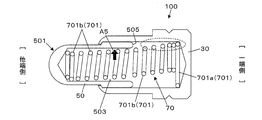
- FIG. 13 is a diagram showing a configuration example of a conventional spring connector 100, and is an end view of a tube 30, a movable pin 50, and a coil spring 70 that vertically traverse the spring connector 100.
- FIG. 14 is a diagram for explaining the configuration of the coil spring 70 in the free state removed from the spring connector 100, and is an end view of one end side of the coil spring 70 that abuts on the bottom of the tube 30.
- the spring connector 100 includes a bottomed tube 30, a movable pin 50, and a coil spring 70.
- the movable pin 50 has a hole 503 in which the tip 501 projects from the opening of the tube 30 and opens in the direction opposite to the protruding direction.
- One end of the coil spring 70 abuts on the bottom of the tube 30, and the other end abuts on the bottom of the hole 503 to urge the movable pin 50 in the protruding direction.
- the coil spring 70 has a plurality of winding portions 701 (701a, 701b). As shown in FIG. 14, the winding portion 701a related to one end portion in contact with the bottom portion of the tube 30 has a larger diameter than the other winding portions 701b. In the free state of the winding portion 701a, the winding center of the other winding portion 701b (indicated by the alternate long and short dash line) is eccentrically arranged with respect to the winding center (indicated by the dotted line) of the winding portion 701a related to one end portion. It is composed of. On the other hand, as shown in FIG. 13, the tube 30 has an inner diameter into which a large-diameter winding portion 701a can be inserted.
- the hole portion of the movable pin 50 has an inner diameter such that a large-diameter winding portion 701a cannot be inserted and only the winding portion 701b can be inserted.
- the center of the bottom of the tube 30 and the center of the bottom of the hole 503 of the movable pin 50 are located on the central axis of the spring connector 100. Therefore, the coil spring 70 housed in the spring connector 100 is at a position where the winding portion 701b near one end is eccentric from the central axis. Further, the winding portion 701b near the other end portion that abuts on the bottom portion of the hole portion 503 is on the central axis or at a position close to the central axis.
- the coil spring 70 is housed in the spring connector 100 in a curved shape in which the winding center of each winding portion 701 is gradually displaced as a whole.
- the winding portion 701a related to one end portion has a large diameter
- the winding portion 701b other than the winding portion 701a is eccentrically arranged with respect to the winding portion 701a. Therefore, the winding portion 701b on one end side close to the winding portion 701a is located in the tube 30, but is located close to the inner peripheral surface of the tube 30.
- the winding portion 701b on one end side close to the winding portion 701a is located in the space behind the rear end surface 505 of the movable pin 50 (in the direction of being pushed in during use).
- the winding portions 701a and 701b on one end side may hinder the movement of the movable pin 50 in the retracting direction. This can impair the contact stability between the movable pin 50 and the tube 30.
- An example of an object of the present invention is to provide a technique capable of improving contact stability between a movable pin and a tube.
- One aspect of the present invention includes a tube, a movable pin having a hole whose tip protrudes from the opening of the tube and opens on the side opposite to the protruding direction, and a coil spring that urges the movable pin in the protruding direction.
- the coil spring is eccentric with the winding center eccentric with respect to the axial straight line connecting the winding center of the winding portion related to one end and the winding center of the winding portion related to the other end.
- a spring connector having a winding portion.
- the coil spring of the spring connector of the present embodiment is configured to have an eccentric winding portion in the effective number of winding portions between the winding portions related to both ends thereof.
- the eccentric winding portion is a portion where the winding center is eccentric with respect to the axial straight line connecting the winding centers of the winding portions related to both ends.
- the winding portion on one end side of the coil spring does not hinder the movement of the movable pin. Therefore, the moving range of the movable pin at the time of use can be widened, and the total length of the spring connector can be shortened accordingly. In addition, the contact stability between the movable pin and the tube can be improved.
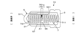
- FIGS. 1 and 2 are views showing a configuration example of the spring connector 10 according to the first embodiment.
- 1 and 2 are views in which the tube 3 and the movable pin 5 are cut out so as to traverse the spring connector 10, and the end face of the tube 3 and the movable pin 5 and the side surface of the coil spring 7 are shown.
- FIG. 1 shows a state in which the movable pin 5 protrudes (protruding state)
- FIG. 2 shows a state in which the tip portion 511 of the movable pin 5 is pushed and retracted into the tube 3 (retracted state).
- the spring connector 10 of the first embodiment includes a bottomed tube 3, a movable pin 5, and a coil spring 7.
- the tip portion 511 of the movable pin 5 projects from the opening of the tube 3.
- the coil spring 7 urges the movable pin 5 in the protruding direction.
- the tube 3 is a bottomed cylindrical body made of a conductive material (for example, copper or a copper alloy), and holds the movable pin 5 slidably on the other end side of the opening.
- the open end of the tube 3 is bent inward by caulking to form a locking portion 31, which prevents the movable pin 5 from coming off.
- the movable pin 5 is made of a conductive material (for example, copper or a copper alloy).
- the movable pin 5 is composed of a small diameter portion 51 and a large diameter portion 53 having an outer diameter larger than that of the small diameter portion 51, and has a hole portion 55 that opens on the side opposite to the protruding direction (one end side).
- the inner diameters of the small diameter portion 51 and the large diameter portion 53 are the same.
- a hole portion 55 having a constant inner diameter is defined by the inner peripheral surface of the small diameter portion 51 and the inner peripheral surface of the large diameter portion 53.
- the tip portion 511 which is the tip of the small diameter portion 51, serves as a contact portion that comes into contact with the terminal to be contacted.
- the small diameter portion 51 and the large diameter portion 53 are connected by a stepped portion having an outer diameter, and the tapered stepped surface 57 between the two is in contact with the locking portion 31 of the tube 3, and the movable pin 5 is formed. It is configured to prevent it from coming off the tube 3. Therefore, the large diameter portion 53 is located in the tube 3 even when the small diameter portion 51 protrudes from the tube 3.
- the coil spring 7 is a coil spring having closed ends at both ends, wherein the winding portion related to both ends 711 and 731 is a countersunk portion.
- the coil spring 7 is made of, for example, a piano wire or a stainless steel wire.
- the coil spring 7 may be made of an insulating material or may be coated with an insulating film.
- one end portion 711 abuts on the bottom portion of the tube 3, and the other end portion 731 abuts on the bottom portion of the hole portion 55 to urge the movable pin 5 in the protruding direction.
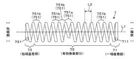
- FIG. 3 is an explanatory diagram illustrating the configuration of the coil spring 7.
- FIG. 3 is a side view in which only the coil spring 7 is extracted from the protruding spring connector 10 shown in FIG.
- the coil spring 7 has an effective winding number portion between the end winding portion 71 related to the one end portion 711, the end winding portion 73 related to the other end portion 731, and the one end portion 711 and the other end portion 731. It is composed of 75 and.
- the countersunk portion 71 is hereinafter appropriately referred to as a “one-sided counterbore portion”.
- the end turn portion 73 is hereinafter appropriately referred to as “the other end end winding portion”.
- the effective number of turns portion 75 has a plurality of winding portions 751 (751a, 751b).
- the portion corresponding to one pitch L2 corresponds to one winding portion 751.
- the winding portion 751 of the effective winding portion 75 is an eccentric winding in which the winding center is eccentric with respect to the axial straight line L1 connecting the winding center of the one end end winding portion 71 and the winding center of the other end end winding portion 73.
- the winding portion 751b is hereinafter appropriately referred to as a “non-eccentric winding portion”.
- one of the winding portions 751 of the effective winding portion 75 is an eccentric winding portion 751a.
- the eccentric winding portion 751a is located inside the hole portion 55 in FIGS. 1 and 2, it may be provided outside the hole portion 55. In this case, when the coil spring 7 itself is pushed and bent, a part of the winding portion 751b located inside the hole portion 55 pushes the inner side surface of the pin to apply lateral pressure.
- the outer diameter of the eccentric winding portion 751a is smaller than the outer diameter of the winding portion 751 (non-eccentric winding portion 751b) adjacent to the eccentric winding portion 751a.
- all the non-eccentric winding portions 751b have the same outer diameter, and the outer diameter of the eccentric winding portion 751a is determined as a smaller outer diameter.
- the eccentric winding portion 751a is provided at the entire length of the coil spring 7 or substantially at the center of the effective winding portion 75, but the position where the coil spring 7 is provided is not limited to this.
- the outer diameter of the one-sided end-winding portion 71 is smaller than the outer diameter of the winding portion 751 (non-eccentric winding portion 751b) adjacent to the one-ended end-winding portion 71.
- the outer diameter of the other end end winding portion 73 is smaller than the outer diameter of the winding portion 751 (non-eccentric winding portion 751b) adjacent to the other end end winding portion 73.
- the end end winding portion 71 and the other end end turn portion 73 have the same outer diameter, and the outer diameter is defined as an outer diameter smaller than that of the non-eccentric winding portion 751b.
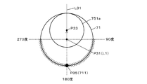
- FIG. 4 is an explanatory diagram for explaining the positional condition of the one end portion 711.
- FIG. 4 schematically shows the positional relationship between the end end winding portion 71 and the eccentric winding portion 751a in a plan view of the one end portion 711 viewed from the linear direction of the axial straight line L1 of FIG.
- the winding of the end end winding portion 71 and the eccentric winding portion 751a is indicated by a circle, and the one end portion 711 is indicated by a large black circle as P35.
- the position of the axial straight line L1 is a position corresponding to the center of the end turn portion 71 at one end, and is indicated by the base point P31 of the black circle in FIG.
- the position of the one end portion 711 is determined based on the line (reference line) L31 from the base point P31 indicating the position of the axial straight line L1 to the winding center P33 of the eccentric winding portion 751a. Specifically, the position of the one end portion 711 is set so that the angle formed by the reference line L31 and the line from the base point P31 to the one end portion 711 is 90 degrees or more and 270 degrees or less in the clockwise direction. ..
- the position of the one end portion 711 is within the angle range indicated by hatching in FIG. 4 which is 90 degrees or more away from the direction of the eccentricity indicated by the arrow in FIG. 4 of the eccentric winding portion 751a. It is stipulated in.
- the positions of the one end portion 711 and the other end portion 731 are defined to be the positions P35 at which the angle formed by the reference line L31 is 180 degrees.
- the position P35 can be said to be a position 180 degrees away from the direction of eccentricity.
- the position of the other end 731 is also determined in the same manner. That is, the line from the base point indicating the position of the axial straight line L1 in the plan view of the other end portion 731 from the linear direction of the axial straight line L1 toward the winding center of the eccentric winding portion 751a is set as the reference line.
- the position of the other end portion 731 is determined as a position where the angle formed by the reference line and the line from the base point toward the other end portion 731 is 90 degrees or more and 270 degrees or less in the clockwise direction in the plan view.
- the action and effect regarding the positions of the one end portion 711 and the other end portion 731 will be described.
- the starting points at which the repulsive force is generated are one end 711 and the other end 731 of the coil spring 7.
- the positions of the one end portion 711 and the other end portion 731 are separated from the direction of the eccentricity indicated by the arrow in FIG. 4 of the eccentric winding portion 751a by more than 90 degrees.
- the circumference is 90 degrees or more and 270 degrees or less. Therefore, the repulsive force generated from the positions of the one end portion 711 and the other end portion 731 acts to move the eccentric winding portion 751a in the direction of the arrow A1 in FIG. 2 (eccentric direction).
- the coil spring 7 can be reliably bent by setting the positional relationship between the one end portion 711 and the other end portion 731 and the eccentric winding portion 751a as described above.
- the effects shown in FIG. 2 are exhibited.
- the movable pin 5 moves in the retracting direction and the coil spring 7 contracts.
- the coil spring 7 bends in the eccentric direction at the portion of the eccentric winding portion 751a.
- the eccentric direction is the direction indicated by the arrow A1 in FIG. 2, and is the direction in which the winding center of the eccentric winding portion 751a is eccentric with respect to the axial straight line L1 from the base point P31 in the plan view shown in FIG. This is the direction toward the winding center P33.
- a force in the eccentric direction acts to press the outer peripheral surface of the movable pin 5 (the outer peripheral portion of the hole portion 55) against the inner peripheral surface of the tube 3. Therefore, the movable pin 5 and the tube 3 can be surely brought into contact with each other during use, and a stable electrical connection between the movable pin 5 and the tube 3 can be realized. Even if the coil spring 7 contracts, the space behind the rear end surface 531 of the movable pin 5 (the direction in which the movable pin 5 is pushed) remains a space. Therefore, the portion on one end side of the coil spring 7 does not hinder the movement of the movable pin 5 in the retracting direction. Therefore, it is possible to provide a technique capable of improving the contact stability of the spring connector 10 without hindering the movement of the movable pin 5 during use.
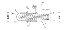
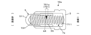
- FIGS. 5 and 6 are views showing a configuration example of the spring connector 10a according to the second embodiment.
- 5 and 6 are views in which the tube 3 and the movable pin 5 are cut out so as to traverse the spring connector 10a, and the end surface of the tube 3 and the movable pin 5 and the side surface of the coil spring 7a are shown.
- FIG. 5 shows the protruding state of the movable pin 5
- FIG. 6 shows the retracted state of the movable pin 5.
- the spring connector 10a of the second embodiment includes a bottomed tube 3, a movable pin 5, and a coil spring 7a, as in the first embodiment.
- the movable pin 5 has a hole portion 55 in which the tip portion 511 protrudes from the opening of the tube 3 and opens in the direction opposite to the protruding direction.
- One end of the coil spring 7a abuts on the bottom of the tube 3 and the other end abuts on the bottom of the hole 55 to urge the movable pin 5 in the protruding direction.
- the coil spring 7a has a configuration in which the winding center of each winding portion 751 of the effective number of turns is gradually displaced as it approaches the eccentric winding portion 751a.
- the winding portion 751 located inside the hole portion 55, and the winding portion 751 near the center corresponds to the eccentric winding portion 751a.
- Each winding portion 751 other than the eccentric winding portion 751a is configured such that the winding center is displaced stepwise from both ends in the eccentric direction of the eccentric winding portion 751a.
- the coil spring 7a has a shape in which the longitudinal direction is bent in the eccentric direction as a whole.
- the arrangement of the eccentric winding portion 751a in the effective number of turns 75 of the coil spring is not limited to the arrangement illustrated in each of the above embodiments.
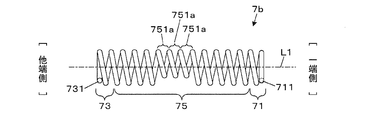
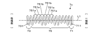
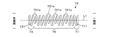
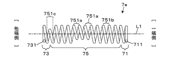
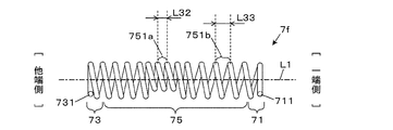
- 7 to 12 are diagrams showing the configurations of coil springs 7b, 7c, 7d, 7e, 7f, and 7g included in the spring connector of the modified example, respectively.
- the effective number of turns portion 75 may have a plurality of eccentric winding portions 751a.
- it has three eccentric winding portions 751a. According to this, it is possible to realize a coil spring 7b having a plurality of eccentric winding portions 751a in the effective number of turns portion 75.
- the non-eccentric winding portion 751b and the eccentric winding portion 751a may be alternately arranged to form the effective number of turns portion 75.
- FIG. 8 shows a configuration example of the effective winding number portion 75 in which two non-eccentric winding portions 751b and two eccentric winding portions 751a are alternately arranged.
- the non-eccentric winding portion 751b and the eccentric winding portion 751a may be alternately arranged one by one. According to this, it is possible to realize the coil spring 7c in which the non-eccentric winding portion 751b and the eccentric winding portion 751a are alternately arranged in the effective number of turns portion 75.
- the eccentric winding portion 751a in the effective number of turns portion 75 may be arranged irregularly. According to this, it is possible to realize the coil spring 7d in which the eccentric winding portion 751a is irregularly arranged in the effective winding number portion 75.
- the effective number of turns portion 75 may have a heterogeneous eccentric winding portion 751c in addition to the non-eccentric winding portion 751b and the eccentric winding portion 751a.
- the heterogeneous eccentric winding portion 751c is eccentrically wound from a base point indicating the position of the axial straight line L1 in a plan view (see FIG. 4) when one end portion 711 or the other end portion 731 of the coil spring is viewed from the linear direction of the axial straight line L1.
- the winding center is formed at a position where the angle formed by the line (reference line) L31 and the line from the base point P31 toward the winding center of the heterogeneous eccentric winding portion 751c is 90 degrees or less.
- the winding portion having the above is a heterogeneous eccentric winding portion 751c.
- the line (reference line) L31 is a line from the base point P31 indicating the position of the axial straight line L1 to the winding center P33 of the eccentric winding portion 751a.
- the effective number of turns portion 75 includes one heterogeneous eccentric winding portion 751c having a winding center in a direction opposite to the direction from the base point toward the winding center of the eccentric winding portion 751a. .. According to this, in the effective number of turns portion 75, it is possible to realize a coil spring 7e having a heterogeneous eccentric winding portion 751c eccentric with respect to the axial straight line L1 in a direction different from the direction in which the eccentric winding portion 751a is located.
- the pitch of the coil spring 7f may be an unequal pitch.
- the pitch L32 of the eccentric winding portion 751a may be narrower than the pitch L33 of the non-eccentric winding portion 751b.
- the pitch L32 of the eccentric winding portion 751a may be wider than the pitch L33 of the non-eccentric winding portion 751b.
- the spring connector can be configured by using the coil springs 7f having unequal pitches.
- the effective number of turns of the coil spring may include winding parts having different outer diameters.
- each winding The outer diameter of the portion 751 may also be gradually reduced as it approaches the eccentric winding portion 751a. According to this, it is possible to realize a coil spring 7g having a winding portion 751 having a different outer diameter in the effective winding number portion 75.
- a coil spring having closed ends at both ends in which the winding portion related to both ends is a countersunk portion, is illustrated, but a configuration using coil springs at both ends is used.
- the closed end is a winding method in which the ends are wound so that there is no space between the spring wires.
- the open end is a winding method in which the ends are spaced by spring wires.
- cross-sectional shape of the coil spring constituting the spring connector is not particularly limited, and may be, for example, a circular shape, an elliptical shape, a polygonal shape, or the like.
- the winding shape of one winding portion is not limited to the circular shape, and may be another shape such as a rectangular shape or an elliptical shape, for example.
- aspects of the present disclosure include a tube, a movable pin having a hole whose tip protrudes from the opening of the tube and opens on the side opposite to the protruding direction, and a coil spring that urges the movable pin in the protruding direction.
- the coil spring is provided with an eccentric winding whose winding center is eccentric with respect to an axial straight line connecting the winding center of the winding portion related to one end and the winding center of the winding portion related to the other end.
- a spring connector with a rotating part.
- the coil spring is configured to have an eccentric winding portion whose winding center is eccentric with respect to an axial straight line connecting the winding centers of the winding portions related to both ends.
- the eccentric winding portion exerts an acting force that pushes the movable pin against the tube. Therefore, the movable pin and the tube can be surely brought into contact with each other during use, and a stable electrical connection between the movable pin and the tube can be realized.
- the winding portion on one end side of the coil spring hinders the movement of the movable pin. Therefore, the moving range of the movable pin at the time of use can be widened, and the total length of the spring connector can be shortened accordingly.
- the contact stability between the movable pin and the tube can be improved.
- the one end portion includes a line from a base point indicating the position of the axial straight line toward the winding center of the eccentric winding portion and a line from the base point toward the one end portion in a plan view from the linear direction of the axial straight line.
- the angle between the two is 90 degrees or more and 270 degrees or less in the clockwise direction.
- the angle formed by the line from the base point toward the winding center of the eccentric winding portion and the line from the base point toward the other end is 90 degrees or more 270 in a clockwise direction. It is in a position below the right angle, May be.
- the coil spring may have closed ends at both ends.
- the outer diameter of the end turn portion related to the one end portion is smaller than the outer diameter of the winding portion adjacent to the end winding portion, and the outer diameter of the end winding portion related to the other end portion is the end winding portion. It may be smaller than the outer diameter of the winding portion adjacent to.
- the eccentric winding portion may be located inside the hole portion.
- the outer diameter of the eccentric winding portion may be smaller than the outer diameter of the winding portion adjacent to the eccentric winding portion.
- the eccentric winding portion is located in an effective winding portion between the one end portion and the other end portion.
- the outer diameter of the eccentric winding portion may be smaller than the outer diameter of the winding portion other than the eccentric winding portion in the effective number of turns.
- the coil spring may have a plurality of the eccentric winding portions.
- the coil spring has a heterogeneous eccentric winding portion having a winding center in a direction different from the direction from the base point toward the winding center of the eccentric winding portion in the effective number of turns in the plan view. May be good.
- the eccentric winding portion is located in an effective winding portion between the one end portion and the other end portion.
- the winding center of each winding portion of the effective winding portion may be gradually displaced as it approaches the eccentric winding portion.
- the coil springs may have an unequal pitch.
Landscapes
- Engineering & Computer Science (AREA)
- General Engineering & Computer Science (AREA)
- Mechanical Engineering (AREA)
- Measuring Leads Or Probes (AREA)
- Springs (AREA)
Priority Applications (3)
| Application Number | Priority Date | Filing Date | Title |
|---|---|---|---|
| CN202180032138.8A CN115552730A (zh) | 2020-05-07 | 2021-04-30 | 弹簧连接器 |
| US17/922,185 US12261402B2 (en) | 2020-05-07 | 2021-04-30 | Spring connector |
| EP21800774.8A EP4148913A4 (en) | 2020-05-07 | 2021-04-30 | SPRING CONNECTOR |
Applications Claiming Priority (2)
| Application Number | Priority Date | Filing Date | Title |
|---|---|---|---|
| JP2020081785A JP7526028B2 (ja) | 2020-05-07 | 2020-05-07 | スプリングコネクタ |
| JP2020-081785 | 2020-05-07 |
Publications (1)
| Publication Number | Publication Date |
|---|---|
| WO2021225121A1 true WO2021225121A1 (ja) | 2021-11-11 |
Family
ID=78409550
Family Applications (1)
| Application Number | Title | Priority Date | Filing Date |
|---|---|---|---|
| PCT/JP2021/017237 Ceased WO2021225121A1 (ja) | 2020-05-07 | 2021-04-30 | スプリングコネクタ |
Country Status (6)
| Country | Link |
|---|---|
| US (1) | US12261402B2 (enExample) |
| EP (1) | EP4148913A4 (enExample) |
| JP (1) | JP7526028B2 (enExample) |
| CN (1) | CN115552730A (enExample) |
| TW (1) | TW202143558A (enExample) |
| WO (1) | WO2021225121A1 (enExample) |
Cited By (1)
| Publication number | Priority date | Publication date | Assignee | Title |
|---|---|---|---|---|
| WO2023228846A1 (ja) * | 2022-05-26 | 2023-11-30 | 株式会社ヨコオ | プローブ |
Citations (4)
| Publication number | Priority date | Publication date | Assignee | Title |
|---|---|---|---|---|
| JPH11162545A (ja) * | 1993-02-10 | 1999-06-18 | Yokowo Co Ltd | 電気接続用コネクタ |
| US20050280433A1 (en) * | 2004-06-16 | 2005-12-22 | Nelson Larre H | Electrical test probes, methods of making, and methods of using |
| CN200953400Y (zh) * | 2006-09-06 | 2007-09-26 | 乔盟弹簧股份有限公司 | 探针式连接器改良结构 |
| WO2011058646A1 (ja) * | 2009-11-13 | 2011-05-19 | テスト ツーリング ソリューションズ グループ ピイ ティ イー リミテッド | プローブピン |
Family Cites Families (4)
| Publication number | Priority date | Publication date | Assignee | Title |
|---|---|---|---|---|
| DE3012491C2 (de) * | 1980-03-31 | 1984-10-25 | Feinmetall Gmbh, 7033 Herrenberg | Kontaktbaustein zum Prüfen von elektrischen Leiterplatten |
| JP2529084Y2 (ja) | 1991-02-22 | 1997-03-12 | 株式会社ヨコオ | スプリングコネクタ |
| JP5568441B2 (ja) * | 2010-10-27 | 2014-08-06 | 日置電機株式会社 | 電源接続端子 |
| KR101552553B1 (ko) * | 2014-09-23 | 2015-10-01 | 리노공업주식회사 | 검사장치용 컨택트 프로브 |
-
2020
- 2020-05-07 JP JP2020081785A patent/JP7526028B2/ja active Active
-
2021
- 2021-04-30 US US17/922,185 patent/US12261402B2/en active Active
- 2021-04-30 EP EP21800774.8A patent/EP4148913A4/en active Pending
- 2021-04-30 CN CN202180032138.8A patent/CN115552730A/zh active Pending
- 2021-04-30 WO PCT/JP2021/017237 patent/WO2021225121A1/ja not_active Ceased
- 2021-05-04 TW TW110116030A patent/TW202143558A/zh unknown
Patent Citations (4)
| Publication number | Priority date | Publication date | Assignee | Title |
|---|---|---|---|---|
| JPH11162545A (ja) * | 1993-02-10 | 1999-06-18 | Yokowo Co Ltd | 電気接続用コネクタ |
| US20050280433A1 (en) * | 2004-06-16 | 2005-12-22 | Nelson Larre H | Electrical test probes, methods of making, and methods of using |
| CN200953400Y (zh) * | 2006-09-06 | 2007-09-26 | 乔盟弹簧股份有限公司 | 探针式连接器改良结构 |
| WO2011058646A1 (ja) * | 2009-11-13 | 2011-05-19 | テスト ツーリング ソリューションズ グループ ピイ ティ イー リミテッド | プローブピン |
Non-Patent Citations (1)
| Title |
|---|
| See also references of EP4148913A4 * |
Cited By (1)
| Publication number | Priority date | Publication date | Assignee | Title |
|---|---|---|---|---|
| WO2023228846A1 (ja) * | 2022-05-26 | 2023-11-30 | 株式会社ヨコオ | プローブ |
Also Published As
| Publication number | Publication date |
|---|---|
| JP7526028B2 (ja) | 2024-07-31 |
| US20230178906A1 (en) | 2023-06-08 |
| TW202143558A (zh) | 2021-11-16 |
| EP4148913A4 (en) | 2024-05-08 |
| EP4148913A1 (en) | 2023-03-15 |
| JP2021177446A (ja) | 2021-11-11 |
| CN115552730A (zh) | 2022-12-30 |
| US12261402B2 (en) | 2025-03-25 |
Similar Documents
| Publication | Publication Date | Title |
|---|---|---|
| US7331821B2 (en) | Electrical connector | |
| JP4770752B2 (ja) | 接触子装置 | |
| WO2015046212A1 (ja) | コネクタ装置 | |
| TW200939580A (en) | Coaxial cable connector for corrugated cable | |
| CN104285340A (zh) | 具有端子的同轴电缆及其制造方法 | |
| WO2015115660A1 (ja) | ガスセンサ | |
| WO2021225121A1 (ja) | スプリングコネクタ | |
| WO2014203758A1 (ja) | コネクタ | |
| JP6290957B2 (ja) | シールド端子の接続構造 | |
| GB2366097A (en) | Hyperboloid electrical socket | |
| EP0748516B1 (en) | Electric lamp | |
| JP7701578B1 (ja) | ケーブルグランド | |
| JP2016131290A (ja) | ノイズフィルタ及びノイズフィルタ用ホルダ | |
| JP2006278336A (ja) | 電気コネクタージャック | |
| US20220416462A1 (en) | Spring connector | |
| WO2021085229A1 (ja) | スプリングコネクタおよびスプリングコネクタの製造方法 | |
| JP2708327B2 (ja) | オス型コネクタを受け取る電気コネクタ | |
| CN118946811A (zh) | 弹簧连接器 | |
| JPH03214574A (ja) | コネクタの接続機構 | |
| JP2021177446A5 (enExample) | ||
| JP2010096735A (ja) | コンタクトプローブ端子 | |
| JP2023174009A5 (enExample) | ||
| JP7560162B2 (ja) | オーディオプラグ | |
| JP7515155B2 (ja) | 圧着接続構造及び圧着接続方法 | |
| US5299953A (en) | Cutting and clamping sleeve contact |
Legal Events
| Date | Code | Title | Description |
|---|---|---|---|
| 121 | Ep: the epo has been informed by wipo that ep was designated in this application |
Ref document number: 21800774 Country of ref document: EP Kind code of ref document: A1 |
|
| NENP | Non-entry into the national phase |
Ref country code: DE |
|
| ENP | Entry into the national phase |
Ref document number: 2021800774 Country of ref document: EP Effective date: 20221207 |
|
| WWG | Wipo information: grant in national office |
Ref document number: 17922185 Country of ref document: US |