WO2021220573A1 - 配線モジュール及び配線モジュールセット - Google Patents
配線モジュール及び配線モジュールセット Download PDFInfo
- Publication number
- WO2021220573A1 WO2021220573A1 PCT/JP2021/004342 JP2021004342W WO2021220573A1 WO 2021220573 A1 WO2021220573 A1 WO 2021220573A1 JP 2021004342 W JP2021004342 W JP 2021004342W WO 2021220573 A1 WO2021220573 A1 WO 2021220573A1
- Authority
- WO
- WIPO (PCT)
- Prior art keywords
- roof
- functional sheet
- wiring module
- interior
- vehicle
- Prior art date
- Legal status (The legal status is an assumption and is not a legal conclusion. Google has not performed a legal analysis and makes no representation as to the accuracy of the status listed.)
- Ceased
Links
Images




Classifications
-
- B—PERFORMING OPERATIONS; TRANSPORTING
- B60—VEHICLES IN GENERAL
- B60R—VEHICLES, VEHICLE FITTINGS, OR VEHICLE PARTS, NOT OTHERWISE PROVIDED FOR
- B60R16/00—Electric or fluid circuits specially adapted for vehicles and not otherwise provided for; Arrangement of elements of electric or fluid circuits specially adapted for vehicles and not otherwise provided for
- B60R16/02—Electric or fluid circuits specially adapted for vehicles and not otherwise provided for; Arrangement of elements of electric or fluid circuits specially adapted for vehicles and not otherwise provided for electric constitutive elements
-
- B—PERFORMING OPERATIONS; TRANSPORTING
- B60—VEHICLES IN GENERAL
- B60R—VEHICLES, VEHICLE FITTINGS, OR VEHICLE PARTS, NOT OTHERWISE PROVIDED FOR
- B60R16/00—Electric or fluid circuits specially adapted for vehicles and not otherwise provided for; Arrangement of elements of electric or fluid circuits specially adapted for vehicles and not otherwise provided for
- B60R16/02—Electric or fluid circuits specially adapted for vehicles and not otherwise provided for; Arrangement of elements of electric or fluid circuits specially adapted for vehicles and not otherwise provided for electric constitutive elements
- B60R16/0207—Wire harnesses
-
- B—PERFORMING OPERATIONS; TRANSPORTING
- B60—VEHICLES IN GENERAL
- B60R—VEHICLES, VEHICLE FITTINGS, OR VEHICLE PARTS, NOT OTHERWISE PROVIDED FOR
- B60R16/00—Electric or fluid circuits specially adapted for vehicles and not otherwise provided for; Arrangement of elements of electric or fluid circuits specially adapted for vehicles and not otherwise provided for
- B60R16/02—Electric or fluid circuits specially adapted for vehicles and not otherwise provided for; Arrangement of elements of electric or fluid circuits specially adapted for vehicles and not otherwise provided for electric constitutive elements
- B60R16/0207—Wire harnesses
- B60R16/0215—Protecting, fastening and routing means therefor
-
- H—ELECTRICITY
- H02—GENERATION; CONVERSION OR DISTRIBUTION OF ELECTRIC POWER
- H02G—INSTALLATION OF ELECTRIC CABLES OR LINES, OR OF COMBINED OPTICAL AND ELECTRIC CABLES OR LINES
- H02G3/00—Installations of electric cables or lines or protective tubing therefor in or on buildings, equivalent structures or vehicles
- H02G3/30—Installations of cables or lines on walls, floors or ceilings
Definitions
- This disclosure relates to a wiring module and a wiring module set.
- Patent Document 1 discloses a wire harness assembly body to be assembled to a vehicle body.
- the wire harness assembly includes a sheet-shaped soundproofing material, a sheet-shaped protective material layered on the soundproofing material, and a wire harness having at least one electric wire arranged between the soundproofing material and the protective material. To be equipped with.
- Patent Document 2 discloses a laying structure of a wiring module including a panel member, a wiring module, and panel peripheral parts.
- the wiring module includes a sheet-like member and at least one electric wire.
- the sheet-like member is laid on the main surface of the panel member.
- At least one electric wire is fixed to the sheet-shaped member so that the sheet-shaped member is laid on the main surface of the panel member and arranged along a predetermined wiring path.
- the panel peripheral parts are provided at a fixed position with respect to the panel member, and the wiring module is positioned with respect to the panel member.
- the wire harness or wiring module as described above may spread widely on the roof of the vehicle. It is desired that such a wire harness or wiring module can be easily incorporated into the roof portion of a vehicle.
- the first object of the present disclosure is to make it possible to easily incorporate the wiring module into the roof portion of the vehicle.
- the second purpose of this disclosure is to make it easy to deal with different grades, the presence or absence of optional parts, and the like.
- the wiring module of the present disclosure is disposed between a roof panel forming a roof portion of a vehicle and an interior member forming a ceiling shape in the vehicle interior, and has a function of spreading in a plane with respect to the roof panel and the interior member.
- the functional sheet includes a functional sheet, a transmission member provided on the functional sheet, a roof-side device provided on the functional sheet, and a rigid member provided on the functional sheet.
- the transmission member includes a layer that performs at least one of a heat insulating function, a soundproofing function, and a radio wave shielding function, and the transmission member is provided along a wiring path in which at least one end of the functional sheet is connected to the roof side device. It is a wiring module.
- the wiring module set of the present disclosure is disposed between the roof panel forming the roof portion of the vehicle and the interior member forming the ceiling shape of the vehicle interior, and is planar with respect to the roof panel and the interior member.
- the functional sheet is provided with a functional sheet that spreads out, a transmission member provided on the functional sheet, and a roof-side device provided on the functional sheet, and the functional sheet has a heat insulating function, a soundproofing function, and a radio wave shielding function.
- the transmission member includes a layer that plays at least one of the above, and the transmission member includes a wiring module and the interior member, which are provided along a wiring path in which at least one end thereof is connected to the roof side device in the functional sheet. It is a wiring module set including an interior member side wiring module including an interior member side transmission member provided in the above.
- the wiring module is easily incorporated in the roof portion of the vehicle.
- wiring module set according to the present disclosure it is possible to easily deal with different grades, the presence or absence of optional parts, and the like.
- FIG. 1 is a schematic perspective view showing a vehicle in which a wiring module is incorporated.
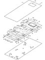
- FIG. 2 is a perspective view showing a wiring module.
- FIG. 3 is an exploded perspective view showing the wiring module.
- FIG. 4 is a functional block diagram relating to the wiring module.
- FIG. 5 is a schematic cross-sectional view showing a wiring module.
- FIG. 6 is a perspective view showing a roof fixing portion provided on the rigid member.
- FIG. 7 is a perspective view showing a roof fixing portion provided on the rigid member.
- FIG. 8 is a cross-sectional view showing the roof fixing portion.
- FIG. 9 is a schematic explanatory view showing the position of the wiring module in the vehicle.
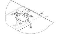
- FIG. 10 is a perspective view showing a modification according to the first embodiment.
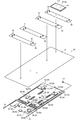
- FIG. 11 is an exploded perspective view showing a wiring module set.
- the wiring module of this disclosure is as follows.
- a functional sheet that is arranged between a roof panel that forms the roof portion of the vehicle and an interior member that forms the ceiling shape of the vehicle interior, and spreads in a plane with respect to the roof panel and the interior member.
- the functional sheet includes a transmission member provided on the functional sheet, a roof-side device provided on the functional sheet, and a rigid member provided on the functional sheet, and the functional sheet has a heat insulating function and soundproofing.
- a wiring module including a layer that performs at least one of a function and a radio wave shielding function, wherein the transmission member is provided along a wiring path in which at least one end of the functional sheet is connected to the roof side device. Is. According to the present disclosure, the portion of the functional sheet provided with the rigid member is less likely to hang down. This allows the wiring module to be easily assembled into the roof portion of the vehicle.
- the roof side device includes a support target roof side device, and the rigid member is provided in a region of the functional sheet where the support target roof side device is provided. May be done. As a result, the roof-side device to be supported is firmly supported by the rigid member.
- the rigid member may include a roof fixing portion fixed to the roof portion of the vehicle. As a result, the rigid member is firmly fixed to the roof portion via the roof fixing portion.
- the roof fixing portion allows the fitting fixing portion to be fitted and fixed to the roof portion of the vehicle to move in the direction in which the functional sheet spreads. It may include a supporting hole. As a result, the fitting fixing portion is supported in a state where the holding hole allows movement in the direction in which the functional sheet spreads. Therefore, the fitting and fixing portion can be easily fitted and fixed to the roof portion.
- the wiring module set disclosed in this disclosure is as follows.
- the interior member side transmission member in the interior member side wiring module and the transmission member in the wiring module can be separately incorporated into the roof portion of the vehicle. Therefore, it is possible to easily deal with different grades and the presence or absence of optional parts.
- a functional sheet that is disposed between the roof panel that forms the roof portion of the vehicle and the interior member that forms the ceiling shape of the vehicle interior, and spreads in a plane with respect to the roof panel and the interior member.
- the functional sheet includes a transmission member provided on the functional sheet and a roof-side device provided on the functional sheet, and the functional sheet has at least one of a heat insulating function, a soundproofing function, and a radio wave shielding function.
- the transmission member includes a layer to be played, and the transmission member includes a wiring module provided at least one end along a wiring path connected to the roof side device in the functional sheet, and an interior member side transmission provided in the interior member. It is a wiring module set including an interior member side wiring module including members. It can easily handle different grades and the presence or absence of optional parts.
- the interior member-side transmission member is a member connected to the roof-side device to be incorporated regardless of whether or not the vehicle is great or has an option, and the transmission member is a member. It may be a member connected to a roof-side device that may or may not be incorporated depending on the vehicle's grade and the presence or absence of options.
- the interior member-side transmission member is fixed to any one of the roof panel, the frame supporting the roof panel, and the interior member. It may be a member connected to the roof side device.
- FIG. 1 is a schematic perspective view showing a vehicle 10 in which the wiring module 20 is incorporated.
- the vehicle 10 includes a body 12.
- the body 12 is a portion forming the outer shape of the vehicle 10.
- the body 12 may be a monocoque body or a body mounted on a ladder frame.
- the body 12 includes a side panel surrounding the passenger compartment, a roof panel 13, a door panel for getting on and off the passengers, a rear door panel for loading and unloading luggage, and the like.
- the body 12 may be formed of metal or resin.
- the body 12 may be made of a combination of metal and resin.
- the plate-shaped portion of the body 12 that covers the upper part of the vehicle interior is the roof panel 13.
- the roof panel 13 forms the roof portion of the vehicle 10.
- the roof panel 13 may be partially or entirely curved to shape the appearance of the body 12.
- the roof panel 13 may be made of metal or resin.
- the roof panel 13 may be made of a combination of metal and resin.
- the roof panel 13 is formed with an antenna hole 13h (see FIG. 2).
- the wiring module 20 is incorporated in the vehicle 10.
- the wiring module 20 is incorporated in the roof portion 14 including the roof panel 13 will be described.
- FIG. 2 is a perspective view showing the wiring module 20.
- the roof portion 14 is shown.
- FIG. 3 is an exploded perspective view showing the wiring module 20.
- the transmission member shown in FIGS. 2 and 3 shows a schematic path, and even if it is drawn as one line, it may include a plurality of electric wires and the like.
- the roof portion 14 may include a frame that supports the roof panel 13.
- the interior member 16 is a plate-shaped member made of resin or the like.
- the interior member 16 is a portion that forms the ceiling shape in the vehicle interior.
- the interior member 16 may be partially or wholly curved.
- the interior member 16 is attached below the roof panel 13.
- the interior member 16 is a portion exposed inside the vehicle interior.
- the interior member 16 is sometimes called a roof liner.
- the wiring module 20 is provided between the roof panel 13 and the interior member 16.
- the wiring module 20 includes a functional sheet 30, a transmission member 40, a roof side device 50, and a rigid member 60.
- the functional sheet 30 includes a layer that performs at least one of a heat insulating function, a soundproofing function, and a radio wave shielding function. That is, the functional sheet 30 is a sheet that has at least one of a heat insulating function, a soundproofing function, and a radio wave shielding function in addition to fixing the transmission member 40, the roof side device 50, and the rigid member 60. Specific examples of the functional sheet 30 having these functions will be described later.
- the functional sheet 30 is incorporated into the roof portion 14 so as to spread in a plane with respect to the roof panel 13 and the interior member 16.
- the functional sheet 30 may be arranged so as to spread over an area of 80% or more with respect to the roof portion 14.
- the functional seat 30 may be arranged so as to spread over the entire headrests of a plurality of passenger seats in the vehicle interior.
- the transmission member 40 is a member that transmits electricity, light, or the like, and at least one end of the functional sheet 30 is a member provided along a wiring path connected to the roof side device 50.
- the transmission member 40 may be a general electric wire having a core wire and a coating around the core wire, or may be a bare wire, a shielded wire, an electric cable, an enamel wire, a nichrome wire, a coaxial wire, an optical fiber, or the like. May be good. That is, the transmission member 40 may be a linear member that transmits electricity.
- the linear member for transmitting electricity may be various signal lines or various power lines.
- the linear transmission member for transmitting electricity may be a single linear object, or a composite of a plurality of linear objects (twisted wire, a plurality of linear objects assembled together and sheathed). It may be a cable covered with (such as a cable).
- the transmission member may be formed by applying a conductive paint to a functional sheet, etching a copper foil, or the like.
- the description is made assuming that the transmission member 40 is an electric wire.
- the transmission member 40 is provided on the functional sheet 30.
- the fact that the transmission member 40 is provided on the functional sheet 30 means that the medium for transmitting electricity or light is formed so as to form an electric or light path in the functional sheet. Therefore, the transmission member 40 provided on the functional sheet 30 is a transmission member directly formed by applying a conductive paint to the functional sheet 30, etching the copper foil, or the like, as well as the functional sheet 30.
- the transmission member 40 provided on the functional sheet 30 is a transmission member directly formed by applying a conductive paint to the functional sheet 30, etching the copper foil, or the like, as well as the functional sheet 30.
- the specific configuration for supporting the transmission member 40 is not particularly limited.
- the transmission member 40 may be fixed to one main surface of the functional sheet 30.
- the transmission member 40 may be welded (also referred to as fusion) to one main surface of the functional sheet 30. In the welded portion formed by this, at least one part of the transmission member 40 and the functional sheet 30 is melted and attached to each other.
- the welding of the transmission member 40 and the functional sheet 30 may be performed by ultrasonic welding or heat welding.
- the transmission member 40 and the functional sheet 30 may be welded by dissolving at least one surface of the transmission member 40 and the functional sheet 30 with a solvent.
- the transmission member 40 may be fixed to the functional sheet 30 with an adhesive, double-sided tape, or the like.
- the transmission member 40 may be sewn to the functional sheet 30 by sewing thread or the like. Further, for example, in a state where the transmission member 40 is arranged on one main surface of the functional sheet 30, an adhesive tape is attached so as to straddle the transmission member 40 from the outside of one main surface of the functional sheet 30. , The transmission member 40 may be fixed to one main surface of the functional sheet 30. The transmission member 40 does not have to be fixed to only one main surface of the functional sheet 30. The transmission member 40 may have both a portion fixed to one main surface of the functional sheet 30 and a portion fixed to the other main surface of the functional sheet 30. In this case, the transmission member 40 may be attached so as to pass from one main surface to the other main surface at the intermediate portion or the edge portion of the functional sheet 30.
- the transmission member 40 may be fixed to the functional sheet 30 by being sandwiched between the two sheets.
- the transmission member 40 may be sandwiched between the sheets constituting each layer.
- the transmission member 40 may be sandwiched between the functional sheet 30 and the other sheet.
- the two sheets sandwiching the transmission member 40 may be fixed by welding, or may be fixed by an adhesive or double-sided tape.
- the transmission member 40 is mainly provided on the surface of the interior member 16 side with respect to the functional sheet 30.
- the transmission member 40 is connected to the roof side device 50.
- the roof side device 50 transmits or receives an electric signal or an optical signal via the transmission member 40.
- the roof-side device 50 receives or distributes electric power via the transmission member 40.
- the connection between the transmission member 40 and the roof side device 50 may be made via a connector.
- the transmission member 40 may be introduced directly into the roof-side device 50 and directly connected to an electrical element in the roof-side device 50.
- the roof side device 50 is a device that is arranged on the roof portion 14 and is a connection destination of the transmission member 40.
- an electronic control unit for example, an electronic control unit, a lamp (particularly a map lamp, an indoor lamp), a speaker, an indoor camera, a monitor, a projection device, an external communication antenna, an indoor antenna, and the like are assumed.
- the roof side device 50 is a device provided on the functional sheet 30.
- the position of the roof side device 50 with respect to the functional sheet 30 is arbitrary.
- the roof-side device 50 is fixed to the functional seat 30 in a position suitable for the role played by the roof-side device 50.
- the roof-side device 50 is a map lamp
- the roof-side device 50 may be fixed to a portion of the functional seat 30 that will be arranged diagonally above and forward of the front seat. ..
- the roof side device 50 is an indoor antenna
- the roof side device 50 is located in a portion of the functional seat 30 which is to be arranged above the front seat or the rear seat. It may be fixed.
- the roof side device 50 may be finally fixed to the roof panel 13, the interior member 16, or the like. Therefore, the roof-side device 50 may be held by the functional sheet 30 with a holding force sufficient to be held at a fixed position on the functional sheet 30.
- the roof side device 50 may be fixed to the functional sheet 30 with an adhesive, an adhesive, double-sided tape, or the like.
- the roof side device 50 may be fixed to the functional sheet 30 by screwing, pinning, or the like.
- the roof side device 50 may be fixed to the functional sheet 30 via the rigid member 60. In this case, the roof-side device 50 may be fixed to the rigid member 60 with an adhesive, an adhesive, double-sided tape, or the like, or may be fixed with screws, pins, or the like.
- FIG. 4 is a functional block diagram related to the wiring module 20.
- typical functional parts are shown regardless of the number of each functional part.
- An example of the roof side device 50 will be described with reference to FIGS. 2 to 4.
- the plurality of roof-side devices 50 include an electronic control unit 51, an indoor-side antenna 52, an external communication antenna unit 53, a lamp 54, a camera 55, and a speaker 56.
- reference numeral 50 may be referred to when generically referred to, and reference numerals 51, 52, 53, 54, 55 and 56 may be referred to when individually distinguishing the roof side devices.
- the electronic control unit 51 is a computer including a processor, a memory, and the like, and executes control processing according to a program stored in advance. It is assumed that the electronic control unit 51 is, for example, an area ECU (Electronic Control Unit) that controls various devices provided on the roof.
- the electronic control unit 51 is connected to the vehicle-side device 18 via a relay transmission member 19. It is assumed that the vehicle-side device 18 is another electronic control unit (for example, body ECU, central ECU, etc.) 18 provided below the roof.
- the vehicle-side device 18 may be a power supply device in place of or in addition to the electronic control unit.
- the relay transmission member 19 includes at least one of a communication line and a power supply line.
- the relay transmission member 19 is arranged along the pillars, for example, and is arranged from the roof toward the vehicle-side equipment.
- the electronic control unit 51 is electrically connected to the vehicle-side device 18 via the relay transmission member 19.
- the electronic control unit 51 is communicably connected to other devices provided on the roof, such as an indoor antenna 52, an external communication antenna unit 53, a lamp 54, a camera 55, and a speaker 56, via a transmission member 40. ing.
- the transmission member 40 may include a communication line.
- the electronic control unit 51 can control other roof-side devices 52, 53, 54, 55, 56 provided on the roof via the transmission member 40.
- the power line may be included in the transmission member 40.
- the power supply line included in the transmission member 40 may be directly connected to the power supply line included in the relay transmission member 19, or may be directly connected to the power supply line included in the relay transmission member 19 via a power supply branch box or the like. good.
- the power supply branch box is a device in which a branch circuit composed of a bus bar or the like, a circuit breaking component composed of a fuse, a semiconductor element, or the like is incorporated.
- the power supply branch box may be incorporated in the electronic control unit 51, or may be configured as a device separate from the electronic control unit 51.
- the positions of the roof-side devices 51, 52, 53, 54, 55, 56 on the functional sheet 30 and the route of the transmission member 40 are arbitrary.
- a part of the electronic control unit 51 and the lamp 54 is provided at the center in the width direction in the region closer to the front of the functional sheet 30.
- the external communication antenna unit 53 is provided at the center in the width direction in the area closer to the rear of the functional sheet 30.
- the direction in which the vehicle travels is the front, and the opposite is the back.
- the left and right are determined based on the state of facing forward.
- the electronic control unit 51 may be provided unevenly to the right or left of the functional sheet 30.
- the external communication antenna unit 53 includes external communication antennas 53a and 53b for performing wireless communication with a device outside the vehicle.
- the external communication antenna unit 53 is formed in a flat shape.
- External communication antennas 53a and 53b are incorporated in the external communication antenna unit 53.
- the external communication antennas 53a and 53b are, for example, an antenna for communicating with a radio base station on a public communication line or a dedicated communication line, an antenna for vehicle-to-vehicle communication or road-to-vehicle communication, and an antenna for receiving GPS signals.
- the external communication antenna unit 53 is a composite antenna unit that includes a plurality of external communication antennas 53a and 53b and performs external communication by a plurality of methods.
- the external communication antenna unit 53 may include only one antenna, or may include three or more antennas.
- the external communication antenna unit 53 is formed in a thin box shape.
- the external communication antenna unit may be formed in a fin shape or a rod shape.
- the external communication antenna unit formed in the shape of a fin or a rod may be inserted into a hole formed in the roof panel and protrude to the outside of the roof panel.
- the external communication antenna can be easily exposed to the outside, and good external communication can be performed through the external communication antennas 53a and 53b.
- the external communication antenna is preferably incorporated in a fin-shaped or rod-shaped external communication antenna unit so as to be located outside the roof panel.
- the external communication antenna unit may not be attached to the functional sheet 30 but may be attached to the body 12. In this case, the connector at the end of the transmission member 40 provided on the functional sheet 30 may be connected to the external communication antenna unit on the body 12 side.
- a plurality of cameras 55 are provided separately in the left side region and the right side region of the functional sheet 30. In each of the left and right regions, a plurality of cameras 55 are provided apart from each other in the front-rear direction. Further, for example, a plurality of speakers 56 are provided separately in each of the left side region and the right side region of the functional sheet 30. In each of the left and right regions, a plurality of speakers 56 are provided apart from each other in the front-rear direction. Further, for example, a plurality of lamps 54 are provided separately in each of the left side region and the right side region of the functional sheet 30. In each of the left and right regions, a plurality of lamps 54 are provided apart from each other in the front-rear direction.
- a camera 55 and a lamp 54 are provided around the frontmost speaker 56, a lamp 54 is provided around the middle speaker 56 in the front-rear direction, and the rearmost speaker 56 is provided.
- a camera 55 and a lamp 54 are provided around the speaker.
- a plurality of indoor antennas 52 are provided on the left and right sides of the functional sheet 30.
- the plurality of indoor antennas 52 are provided behind the electronic control unit 51 and in front of the external communication antenna unit 53.
- a plurality of indoor antennas 52 are provided separately on the left and right sides, and further divided on the front and back sides. More specifically, the plurality of indoor antennas 52 are arranged in an area corresponding to the seat, more specifically, in a position above the left and right seating points of the driver's seat, the passenger seat, and the rear seat.
- the indoor antenna 52 is used, for example, for non-contact power feeding (Wi-Fi (registered trademark) power feeding) or the like.
- Each roof side device 51, 52, 53, 54, 55, 56 may be provided on any surface of the functional sheet 30.
- the external communication antenna unit 53 is provided on the surface of the functional sheet 30 on the roof panel 13 side.
- the electronic control unit 51, the indoor antenna 52, the lamp 54, the camera 55, and the speaker 56 are provided on the surface of the functional sheet 30 on the interior member 16 side.
- the transmission member 40 is connected to each roof side device 52, 53, 54, 55, 56 from the electronic control unit 51 through a path divided into two directions on the left and right. For example, focusing on the region to the left of the functional sheet 30, a part of the transmission member 40 extends to the left from the electronic control unit 51. A part of the transmission member 40 bends in front of the left edge of the functional sheet 30 and extends forward or backward along the left edge, and each roof side device 52 provided on the left side of the functional sheet 30. It is connected to 53, 54, 55 and 56. Further, for example, focusing on the region to the right of the functional sheet 30, another part of the transmission member 40 extends to the right from the electronic control unit 51. Some of the other transmission members 40 are bent in front of the right edge of the functional sheet 30 and extend forward or backward along the right edge, and each roof-side device provided on the right side of the functional sheet 30. It is connected to 52, 53, 54, 55, 56.
- the relay transmission member 19 extends forward from the electronic control unit 51.
- the relay transmission member 19 is separated from the electronic control unit 51 to the left and right, and extends forward along the left and right edges of the functional sheet 30.
- the relay transmission member 19 is guided to the vehicle body side along the A pillar, for example.
- the relay transmission member 19 may be directly drawn from the electronic control unit 51, or may be connected to the electronic control unit 51 via a connector.
- the relay transmission member 19 may not be attached to the functional sheet 30 and may be guided toward the A pillar or the like in a state of being separated from the functional sheet 30.
- the transmission member 40 may penetrate the functional sheet 30.
- the transmission member 40 connected to the external communication antenna unit 53 is routed from the electronic control unit 51 through the surface of the functional sheet 30 on the interior member 16 side to the vicinity of the external communication antenna unit 53. It may be pulled out to the roof panel 13 side through the functional sheet 30 near the external communication antenna unit 53.
- the rigid member 60 is a member provided on the functional sheet 30.
- the rigid member 60 is a member that imparts difficulty in deforming to the functional sheet 30.
- the rigid member 60 is preferably more rigid than the functional sheet 30.
- the high and low rigidity here is determined by, for example, a plane orthogonal to the longitudinal direction of the rigid member 60 as a reference plane, the flexural rigidity of the rigid member 60 on the reference plane, and the rigid member 60 of the functional sheet 30. It may be evaluated by the flexural rigidity at the reference plane in the provided partial region.
- the functional sheet 30 is a laminate of aluminum foil and a non-woven fabric
- the rigid member 60 is a plate or bar made of a resin (for example, PP (polypropylene), PA (polyamide), etc.) in which the contents are buried. There may be.
- the rigid member 60 may be a member that has been made lighter while having strength, such as a honeycomb structure member.
- the rigid member 60 may be made of a metal such as iron or aluminum.
- the rigid member 60 is fixed to the functional sheet 30 with an adhesive, an adhesive, double-sided tape, welding (ultrasonic welding, heat welding, etc.) or the like.
- the rigid member 60 may be fixed to the functional sheet 30 by screwing, pinning, or the like.
- the rigid member 60 is formed in the shape of an elongated rectangular plate.
- the length dimension of the rigid member 60 is set to be the same as the width dimension of the functional sheet 30.
- the length dimension of the rigid member 60 may be smaller than the width dimension of the functional sheet 30 so that the edge of the functional sheet 30 does not hang down (for example, it is small in the range of 20 cm or less).
- the rigid member 60 is arranged on the surface of the functional sheet 30 on the roof panel 13 side. The facing surfaces of both are joined by an adhesive or the like.
- a plurality of (four in this case) rigid members 60 are fixed to the functional sheet 30.
- the longitudinal direction of each rigid member 60 is along the width direction of the functional sheet 30. Therefore, the portion of the functional sheet 30 provided with the rigid member 60 is kept so as not to hang down in the width direction.
- the plurality of rigid members 60 are provided at intervals in the front-rear direction with respect to the functional sheet 30. Therefore, the functional sheet 30 can be bent between the plurality of rigid members 60.
- the storage space and the transportation space of the wiring module 20 can be reduced by folding the functional sheet 30 between the plurality of rigid members 60.
- the arrangement area of the rigid member 60 with respect to the functional sheet 30 is arbitrary.
- the rigid member 60 may be provided in a partial region with respect to the functional sheet 30.
- the rigid member 60 may be provided in the area of the functional sheet 30 where the speaker 56 is provided.
- a plurality of speakers 56 are provided in three front-rear regions in the front-rear direction of the functional sheet 30.
- the rigid member 60 is provided in three regions where the speaker 56 is provided. In each of these regions, the rigid member 60 is fixed to the surface of the functional sheet 30 on the roof panel 13 side, and the speaker 56 is fixed to the surface of the interior member 16 side.
- the rigid member 60 may be provided in the area of the functional sheet 30 where the external communication antenna unit 53 is provided. good.
- an external communication antenna unit 53 is provided in a region closer to the rear of the functional sheet 30.
- the rigid member 60 is provided in the area where the external communication antenna unit 53 is provided. In this region, the rigid member 60 is fixed to the surface of the functional sheet 30 on the roof panel 13 side, and the external communication antenna unit 53 is fixed to the upper side thereof.
- the external communication antenna unit 53 may be fixed to the functional sheet 30 at the outer portion of the rigid member 60.
- the external communication antenna unit 53 may be fixed to the rigid member 60.
- the roof-side equipment to be supported may be all or a part of the plurality of roof-side equipment 50.
- the roof-side device to be supported may be the heaviest device among the plurality of roof-side devices 50.
- the speaker 56 and the external communication antenna unit 53 are examples of heavy equipment.
- the equipment on the roof side to be supported may be equipment exposed in the vehicle interior, for example, a lamp 54, a camera 55, a switch, or the like. These devices can be pushed out of the passenger compartment. Therefore, if the rigid member 60 is arranged on the outside of these devices, the pressed force can be received by the rigid member 60.
- each roof side device 50 may be fixed to any location while the wiring module 20 is incorporated in the roof portion 14.
- the roof side device 50 may be fixed to the roof panel 13 or a frame supporting the roof panel 13.
- the roof side device 50 may be fixed to the interior member 16.
- the roof-side device 50 may only be fixed to the rigid member 60.
- the rigid member 60 preferably includes a roof fixing portion 70 fixed to the roof portion 14 which is a roof portion of the vehicle.
- a roof fixing portion 70 projecting upward is formed on the rigid member 60.
- the roof fixing portion 70 is a portion of the roof portion 14 that is fixed to the roof panel 13 or a frame that supports the roof panel 13. It is assumed that the roof fixing portion 70 is, for example, a clip-shaped portion that is fixed by insertion to prevent it from coming off, a screw, or the like. It is not essential that the rigid member 60 be fixed to the roof portion 14.
- FIG. 5 is a schematic cross-sectional view showing the wiring module 20.
- the roof panel 13, the frame 13F supporting the roof panel 13, and the interior member 16 are shown.
- the frame 13F is, for example, a long rigid member arranged inside the roof panel 13, and is a member called a reinforcing bar or a stay.
- the frame 13F is arranged, for example, along the vehicle width direction.
- the rigid member 60 is fixed to the frame 13F via the roof fixing portion 70.
- the functional sheet 30 is located on the interior member 16 side with respect to the rigid member 60.
- An electronic control unit 51, an indoor antenna 52, a lamp 54, a camera 55, a speaker 56, etc. are held on the surface of the interior member 16 with respect to the functional sheet 30.
- the electronic control unit 51, the indoor antenna 52, the lamp 54, the camera 55, and the speaker 56 may be simply mounted on the interior member 16, or are fixed to the interior member 16 by an fitting structure. You may.
- the lamp 54 and the camera 55 may be exposed in the vehicle interior.
- the interior member 16 may be formed with a recess 16h into which the lamp 54 and the camera 55 can be fitted, and the recess 16h may be formed with an opening 16ha for exposing the lamp 54 and the camera 55 into the vehicle interior. ..
- a functional sheet 30 is provided above the lamp 54 and the camera 55, and a rigid member 60 is provided above the functional sheet 30. Therefore, even if the lamp 54 and the camera 55 are pushed, the force is received by the rigid member 60, and the lamp 54 and the camera 55 are prevented from retracting from the interior member 16 to the roof panel 13 side. ..
- An external communication antenna unit 53 is provided on the surface of the roof panel 13 side with respect to the functional sheet 30.
- the rigid member 60 between the external communication antenna unit 53 and the functional sheet 30 may be fixed to the frame 13F on the outer side of the external communication antenna unit 53 via the roof fixing portion 70.
- the external communication antenna unit 53 is exposed to the outside through the antenna hole 13h formed in the roof panel 13.
- the functional sheet 30 is arranged between the interior member 16 and the roof panel 13.
- the functional sheet 30 may be fixed to the interior member 16 or the like, or may be simply placed on the interior member 16.
- the functional sheet 30 may be fixed to the interior member 16 or the like by double-sided tape, an adhesive, welding or the like.
- the functional sheet 30 includes a layer that performs at least one of a heat insulating function, a soundproofing function, and a radio wave shielding function.
- the functional sheet 30 includes a non-woven layer 32 and a radio wave shielding layer 34.
- the functional sheet 30 has a multi-layer structure in which the non-woven layer 32 and the radio wave shielding layer 34 are superposed from the lower side to the upper side.
- the stacking order of each layer is arbitrary.
- the radio wave shielding layer 34 may be provided under the non-woven layer 32.
- the functional sheet has a plurality of functional layers, it is not essential that the plurality of functional layers are arranged so as to overlap each other in the thickness direction of the functional sheet.
- the plurality of functional layers may be provided in different regions within the region where the functional sheet spreads. For example, a plurality of functional layers may be provided side by side in an area where the functional sheet spreads. Another functional layer may be partially provided for one functional layer.
- the non-woven layer 32 is an example of a layer having a heat insulating property that makes it difficult for heat to be transferred between one main surface side and the other main surface side of the functional sheet 30.
- the heat insulating layer may be a layer that reflects heat radiant energy.
- the heat insulating layer may be a layer having a lower thermal conductivity than the other layers.
- a non-woven sheet or a sheet containing fine gaps such as a foamed sheet may be used.
- a heat insulating paint or a heat insulating paint may be used as the heat insulating layer.
- the non-woven layer 32 is an example of a layer having soundproofing property that makes it difficult for sound to be transmitted between one main surface side and the other main surface side of the functional sheet 30.
- the soundproofing layer may be one that reflects sound or one that absorbs sound energy as heat energy.
- a non-woven sheet or a sheet having fine gaps such as a foamed sheet may be used.
- a sound absorbing paint may be used.
- the heat insulating layer and the soundproofing layer may be provided as physically separate layers.
- the radio wave shielding layer 34 is a layer that makes it difficult for radio waves to be transmitted between one main surface side and the other main surface side of the functional sheet 30.
- the radio wave shielding layer 34 may have radio wave shielding properties for all frequencies.
- the radio wave shielding layer 34 may have a radio wave shielding property that is selective for a part of the frequency band. In this case, radio waves in some frequency bands need only be reflected or absorbed by the radio wave shielding layer.
- the radio wave shielding layer 34 may be a layer formed of a metal foil such as aluminum or iron.
- a well-known frequency selection film (FSS: Frequency Selective Surface) may be used as the radio wave shielding layer 34 having the selective radio wave shielding property.
- FIG. 5 is a diagram showing an example of a frequency selection film.
- the frequency selection film is formed by forming a unit cell (element) with a metal foil or the like on a base film formed of a resin or the like.
- a frequency selection film has a property of selectively blocking radio waves in one or a plurality of frequency bands according to the frequency characteristics of a unit cell (element) and allowing radio waves in other frequency bands to pass through.
- the radio wave shielding layer having selective radio wave shielding property may be formed by printing a conductive paste or the like directly on the heat insulating layer or the soundproofing layer.
- each layer may simply be superposed.
- Each layer may be fixed by double-sided tape, an adhesive, welding or the like.
- the external communication antenna unit 53 is provided on the outside of the vehicle with respect to the radio wave shielding layer 34.
- the radio waves radiated from the external communication antennas 53a and 53b are shielded by the radio wave shielding layer 34, and it becomes difficult for them to propagate to the vehicle interior side.
- the radio waves radiated from the external communication antennas 53a and 53b are propagated to the outside without being shielded by the radio wave shielding layer 34. Therefore, wireless communication with an external device (base station or the like) via the external communication antennas 53a and 53b is satisfactorily performed.
- the indoor side antenna 52 is provided on the vehicle interior side with respect to the radio wave shielding layer 34.
- the radio waves radiated from the indoor antenna 52 and the indoor equipment in the vehicle interior are shielded by the radio wave shielding layer 34, and it becomes difficult for the radio waves to propagate to the outside of the vehicle.
- the radio waves that perform wireless communication with the indoor antenna 52 are shielded by the radio wave shielding layer 34, and it becomes difficult for the radio waves to propagate to the outside of the vehicle.
- the radio wave radiated by the indoor antenna 52 is propagated to the vehicle interior side opposite to the radio wave shielding layer 34 with respect to the indoor antenna 52.
- wireless communication can be satisfactorily performed with the indoor device through the indoor antenna 52. Further, when the indoor antenna 52 performs non-contact power supply to the indoor device, radio waves (electric power) do not leak to the outside of the vehicle, so that non-contact power supply is efficiently performed.
- the indoor antenna 52 is relatively thin and lightweight, it is only fixed to the functional sheet 30 and does not have to be fixed to the interior member 16.
- FIG. 6 and 7 are perspective views showing a roof fixing portion 70 provided on the rigid member 60.
- FIG. 8 is a cross-sectional view showing the roof fixing portion 70.
- the roof fixing portion 70 has a configuration in which the fitting fixing portion 72 is held in the holding hole 64 formed in the rigid member 60.
- the holding hole 64 is formed in a plate-shaped portion 61 of the rigid member 60. That is, the rigid member 60 is provided with a plate-shaped portion 61 extending along the main surface direction thereof.
- the plate-shaped portion 61 may be a portion integrally formed with a portion of the rigid member 60 fixed to the functional sheet 30, or is separately welded and adhered to the portion fixed to the functional sheet 30. , It may be a part attached by screwing, a fitting structure, or the like.
- a holding hole 64 is formed at a position separated inward from the edge of the plate-shaped portion 61.
- the holding hole 64 is formed in a circular hole shape.
- a slit-shaped introduction portion 65 is formed so as to face the edge of the plate-shaped portion 61 from the holding hole 64.
- the introduction portion 65 includes a pair of guide edges 65a that gradually narrow from the edge of the plate-shaped portion 61 toward the holding hole 64.
- a relief opening 65h is formed in a portion away from the pair of guide edges 65a. Therefore, the pair of guide edges 65a can be elastically deformed so as to narrow the relief opening 65h and widen the space between the pair of guide edges 65a.
- Auxiliary plate-shaped portions 66 are formed at intervals with respect to the plate-shaped portions 61.
- An auxiliary hole 67 is formed in a portion of the auxiliary plate-shaped portion 66 facing the holding hole 64. Between the plate-shaped portion 61 and the auxiliary plate-shaped portion 66, a gap is provided in the peripheral portion of the holding hole 64 in which the head 74 described later can be arranged.
- the auxiliary plate-shaped portion 66 may be omitted.
- the fitting fixing portion 72 includes a fitting main body portion 73 and a fitting state holding pin 77.
- the fitting main body 73 is a member made of resin or the like, and includes a head 74 and an insertion portion 75.
- the head 74 is formed in a disk shape.
- the insertion portion 75 is formed in a shape protruding from one main surface of the head 74. More specifically, the insertion portion 75 is formed in a cylindrical shape.
- a plurality of slits 75S are formed in the insertion portion 75 along the axial direction thereof.
- the tip portion 75e of the insertion portion 75 is formed so as to face inward. The insertion portion 75 can be deformed so as to widen the tip end side thereof.
- the fitting state holding pin 77 is fitted into the insertion portion 75 through the opening 74h.
- the fitted state holding pin 77 includes a pin head 78 and a columnar portion 79.
- the pin head 78 is formed in a disk shape that can be arranged in the opening 74h.
- the columnar portion 79 is formed in a long shape protruding from the pin head 78.
- the tip of the pin head 78 is formed on a first guide surface 79a that gradually becomes thicker from the tip side to the base end side.
- the longitudinal intermediate portion of the pin head 78 is formed in a groove portion 79b that is recessed inward along the circumferential direction thereof.
- the tip portion 75e of the insertion portion 75 is fitted into the groove portion 79b.
- the base end portion of the pin head 78 is formed on a second guide surface 79c that gradually becomes thinner from the tip end side toward the base end side.
- the auxiliary hole 67 in the auxiliary plate-shaped portion 66 is formed to have an outer diameter larger than the outer diameter of the pin head 78.
- the pin head 78 of the fitting state holding pin 77 is in a state of protruding outward from the head 74 of the fitting main body 73.
- the base end portion of the insertion portion 75 in the fitting fixing portion 72 is held in the holding hole 64, and the head 74 is arranged between the plate-shaped portion 61 and the auxiliary plate-shaped portion 66.
- the fitting fixing portion 72 is supported with respect to the rigid member 60.
- the insertion portion 75 is held by the narrow portion between the holding hole 64 and the introduction portion 65 so as not to come off from the holding hole 64.
- the insertion portion 75 When the rigid member 60 is fixed to the frame 13F or the like, the insertion portion 75 is fitted into the fixing hole 13F formed in the frame 13F. After that, the fitting state holding pin 77 is pushed toward the fitting main body 73. Then, the tip portion 75e of the insertion portion 75 is extruded outward by the first guide surface 79a of the pin head 78. As a result, the outward portion of the tip of the insertion portion 75 is caught or in contact with the fixing hole 13F formed in the frame 13F so as not to come off.
- the fitting state holding pin 77 is further pushed in, and the tip portion 75e of the insertion portion 75 is fitted into the groove portion 79b of the pin head 78, so that the fitting fixing portion 72 is fitted into the fixing hole 13F formed in the frame 13F. It is kept in a good condition.
- the outward surface of the pin head 78 may be located on an extension of the outward surface of the head 74. As a result, the pin head 78 is less likely to be inadvertently pushed.
- the pin head 78 When the pin head 78 is further pushed in from the above state, the fitted state between the tip portion 75e of the insertion portion 75 and the groove portion 79b of the pin head 78 is released, and the tip portion 75e of the insertion portion 75 becomes the pin head 78. It is in a state where it can be retracted inward with respect to the second guide surface 79c. As a result, the state of being caught or in contact between the outwardly facing portion of the tip of the insertion portion 75 and the fixing hole 13F is eliminated, and the fitting fixing portion 72 can be separated from the fixing hole 13F formed in the frame 13F. With such a configuration, the rigid member 60 can be easily attached to the frame 13F and can be easily removed.
- the roof side device 50 and the transmission member 40 are provided on the functional sheet 30. Therefore, the wiring module 20 can easily incorporate the functional sheet 30, the roof side device 50, and the transmission member 40 into the roof portion 14. At this time, it is conceivable that the functional sheet 30 hangs down due to its own weight. Further, it is conceivable that the weight of the roof side device 50 provided on the functional sheet 30 and the weight of the transmission member 40 cause it to hang down. Since the wiring module 20 may greatly spread below the roof portion 14, if a part of the wiring module 20 hangs down, it becomes difficult to incorporate the wiring module 20 into the roof portion 14.
- the wiring module 20 is provided with a rigid member 60 on the functional sheet 30. Therefore, the portion of the functional sheet 30 provided with the rigid member 60 is less likely to hang down. As a result, the wiring module 20 can be easily incorporated into the roof portion 14.
- FIG. 9 is a schematic explanatory view showing the position of the wiring module 20 in the vehicle 10.
- FIG. 9 shows the positional relationship on the plane perpendicular to the left-right direction.
- the wiring module 20 is provided between the interior member 16 and the roof panel 13.
- Vehicle-side devices 18A and 18B are provided on the vehicle body side.
- the vehicle-side devices 18A and 18B are, for example, devices provided below the interior member 16 in the body 12.
- Vehicle-side devices 18A, 18B as described above, body ECU, central ECU, etc., and may be a power supply device.
- the vehicle-side device 18A is an ECU
- the vehicle-side device 18B is a power supply device.
- the relay transmission member 19 drawn out from the vehicle side devices 18A and 18B is pulled out between the roof panel 13 and the interior member 16 through the A pillar 11P and the like, and is connected to the electronic control unit 51. As described above, the relay transmission member 19 may be introduced directly into the electronic control unit 51 or may be connected via a connector.
- the wiring module 20 When assembling the wiring module 20 to the roof panel 13, for example, it is done as follows. That is, an operator or the like lifts the wiring module 20 from below the roof panel 13 and attaches it to the roof panel 13. At this time, an operator or the like lifts the portion of the wiring module 20 provided with the rigid member 60 from below (see arrow P). Then, the wiring module 20 is assembled to the roof panel 13 in a state of being supported so as not to hang down even if there are relatively few support points. Therefore, the wiring module 20 can be easily assembled to the roof panel 13.
- the rigid member 60 is provided in the area of the functional sheet 30 where the roof side devices to be supported (external communication antenna unit 53, lamp 54, camera 55) and the like are provided, they are supported from the indoor side. Even when the roof side device is pushed, it can be firmly supported by the rigid member 60.
- the rigid member 60 is fixed to the roof portion 14 via the roof fixing portion 70, the rigid member 60 is firmly fixed to the roof portion 14.
- the holding hole 64 in the rigid member 60 supports the fitting fixing portion 72 in a state of allowing movement in the direction in which the functional sheet 30 spreads. Therefore, when the rigid member 60 of the functional sheet 30 is fixed to the roof portion 14, if there is a manufacturing error, an assembly error, or the like, the fitting fixing portion is aligned with the position of the fixing hole 13F on the frame 13F. The position of 72 is adjusted. Therefore, the fitting fixing portion 72 is easily fitted and fixed to the roof panel 13.
- FIG. 10 is a perspective view showing a modified example according to the first embodiment.
- the roof side device 50 when the functional sheet 30 exists between the roof side device 50 and the rigid member 60, the roof side device 50 may be directly fixed to the rigid member 60.
- the fixing piece 152 is projected from the roof side device 50, and the opening 131h is formed in the region of the functional sheet 30 corresponding to the fixing piece 152.
- the fixing member S such as a screw is inserted into the insertion hole 152h formed in the fixing piece 152, and is fixed to the fixing hole formed in the rigid member 60 through the opening 131h by screw tightening or the like. There may be.
- FIG. 11 is an exploded perspective view showing the wiring module set 210.
- the roof portion 14 is shown.
- the wiring module set 210 includes a wiring module 20 and an interior member side wiring module 220.
- the wiring module 20 may have the same configuration as that described in the first embodiment.
- the interior member side wiring module 220 is a wiring module provided on the interior member 16.
- the interior member side wiring module 220 includes an interior member side transmission member 240.
- the interior member side transmission member 240 may be the same as the transmission member 40. Here, the description is made on the assumption that the transmission member 240 on the interior member side is an electric wire.
- the interior member side transmission member 240 is connected to a roof side device 250 among the devices incorporated in the roof portion 14.
- the interior member-side transmission member 240 may be directly guided into the roof-side device 250 and directly connected to the electric components inside the roof-side device 250, or may be connected via a connector.
- the roof side device 250 is not fixed to the functional sheet 30.
- the roof side device 250 may be fixed to the interior member 16, the roof panel 13, the frame 13F, or the like.
- FIG. 11 shows an example in which the roof side device 250 is fixed to the interior member 16.
- the interior member side wiring module 220 may be incorporated into the roof portion 14 together with the roof side device 250, or may be incorporated into the roof portion 14 separately from the roof side device 250, and may be incorporated into the roof side device 250 at the roof portion 14. It may be connected to a connector.
- the interior member side transmission member 240 may be fixed to the interior member 16 with an adhesive tape, an adhesive, or the like.
- the interior member side transmission member 240 may have a wiring path independent of the wiring module 20.
- the interior member side transmission member 240 may be connected to the vehicle side device via a relay transmission member 219 different from the relay transmission member 19.
- the interior member side transmission member 240 in the interior member side wiring module 220 and the transmission member 40 in the wiring module 20 can be separately incorporated into the roof portion 14 of the vehicle. Therefore, it is possible to easily deal with different grades and the presence or absence of optional parts.
- a plurality of roof-side devices incorporated in the roof portion 14 are a roof-side device (which may be referred to as a common roof-side device, for example, a map lamp) and a vehicle, which are incorporated regardless of the vehicle's grade and options. It is classified as a roof-side device (which may be referred to as an arbitrary roof-side device, for example, a camera, an indoor antenna, etc.) that may or may not be incorporated depending on the presence or absence of options.
- the former wiring connected to the roof-side device may be incorporated into the interior member-side wiring module 220 as the interior member-side transmission member 240.
- the wiring connected to the latter roof-side device may be incorporated into the wiring module 20 as a transmission member 40.
- Vehicle 11P A pillar 12 Body 13 Roof panel 13F Frame 13F Fixing hole 13h Antenna hole 14 Roof part 16 Interior member 16h Recess 16ha Opening 18, 18A, 18B Vehicle side equipment 19 Relay transmission member 20 Wiring module 30 Functional sheet 32 Non- Woven layer 34 Radio wave shielding layer 40 Transmission member 50, 250 Roof side equipment 51 Electronic control unit (roof side equipment) 52 Indoor antenna (roof side equipment) 53 External communication antenna unit (roof side device) 53a, 53b External communication antenna 54 lamp (roof side equipment) 55 Camera (roof side equipment) 56 Speaker (roof side equipment) 60 Rigid member 61 Plate-shaped part 64 Holding hole 65 Introduction part 65a Guide edge 65h Escape opening 66 Auxiliary plate-shaped part 67 Auxiliary hole 70 Roof fixing part 72 Fitting fixing part 73 Fitting body part 74 Head 74h Opening 75 Insertion part 75S Slit 75e Tip 77 Fitted state holding pin 78 Pin head 79 Columnar part 79a First guide surface 79b Gro
Landscapes
- Engineering & Computer Science (AREA)
- Mechanical Engineering (AREA)
- Architecture (AREA)
- Civil Engineering (AREA)
- Structural Engineering (AREA)
- Vehicle Interior And Exterior Ornaments, Soundproofing, And Insulation (AREA)
Abstract
配線モジュールを、車両における屋根部分に容易に組込めるようにすることを目的とする。車両の屋根部分を形成するルーフパネルと車室内の天井形状を形作る内装部材との間に配設され、前記ルーフパネルと前記内装部材とに対して面状に広がる機能性シートと、前記機能性シートに設けられた伝送部材と、前記機能性シートに設けられたルーフ側機器と、前記機能性シートに設けられた剛性部材と、を備え、前記機能性シートは、断熱機能、防音機能及び電波遮蔽機能のうちの少なくとも1つを奏する層を含み、前記伝送部材は、前記機能性シートにおいて少なくとも一端が前記ルーフ側機器に接続される配線経路に沿って設けられている、配線モジュールである。
Description
本開示は、配線モジュール及び配線モジュールセットに関する。
特許文献1は、車両のボディに組付けられるワイヤハーネス組付体を開示している。ワイヤハーネス組付体は、シート状の防音材と、防音材に重ねられたシート状の保護材と、防音材と保護材との間に配索された少なくとも一本の電線を有するワイヤハーネスとを備える。
特許文献2は、パネル部材と、配線モジュールと、パネル周辺部品とを備える配線モジュールの敷設構造を開示している。配線モジュールは、シート状部材と少なくとも1つの電線とを含む。シート状部材は、パネル部材の主面上に敷設される。少なくとも1つの電線は、シート状部材がパネル部材の主面上に敷設された状態で所定の配線経路に沿って配設されるようにシート状部材に固定されている。パネル周辺部品は、パネル部材に対して一定位置に設けられ、配線モジュールをパネル部材に対して位置決めする。
上記のようなワイヤハーネス又は配線モジュールは、車両の屋根部分に大きく広がることがある。このようなワイヤハーネス又は配線モジュールを、車両の屋根部分に容易に組込めるようにすることが望まれている。
また、グレード違い、オプション部品の有無等に容易に対応できるようにすることが望まれている。
そこで、本開示は、配線モジュールを、車両における屋根部分に容易に組込めるようにすることを第1の目的とする。
また、本開示は、グレード違い、オプション部品の有無等に容易に対応できるようにすることを第2の目的とする。
本開示の配線モジュールは、車両の屋根部分を形成するルーフパネルと車室内の天井形状を形作る内装部材との間に配設され、前記ルーフパネルと前記内装部材とに対して面状に広がる機能性シートと、前記機能性シートに設けられた伝送部材と、前記機能性シートに設けられたルーフ側機器と、前記機能性シートに設けられた剛性部材と、を備え、前記機能性シートは、断熱機能、防音機能及び電波遮蔽機能のうちの少なくとも1つを奏する層を含み、前記伝送部材は、前記機能性シートにおいて少なくとも一端が前記ルーフ側機器に接続される配線経路に沿って設けられている、配線モジュールである。
また、本開示の配線モジュールセットは、車両の屋根部分を形成するルーフパネルと車室内の天井形状を形作る内装部材との間に配設され、前記ルーフパネルと前記内装部材とに対して面状に広がる機能性シートと、前記機能性シートに設けられた伝送部材と、前記機能性シートに設けられたルーフ側機器と、を備え、前記機能性シートは、断熱機能、防音機能及び電波遮蔽機能のうちの少なくとも1つを奏する層を含み、前記伝送部材は、前記機能性シートにおいて少なくとも一端が前記ルーフ側機器に接続される配線経路に沿って設けられている、配線モジュールと、前記内装部材に設けられる内装部材側伝送部材を備える内装部材側配線モジュールと、を備える配線モジュールセットである。
本開示に係る上記配線モジュールによれば、配線モジュールが、車両における屋根部分に容易に組込まれる。
本開示に係る上記配線モジュールセットによれば、グレード違い、オプション部品の有無等に容易に対応できる。
[本開示の実施形態の説明]
最初に本開示の実施態様を列記して説明する。
最初に本開示の実施態様を列記して説明する。
本開示の配線モジュールは、次の通りである。
(1)車両の屋根部分を形成するルーフパネルと車室内の天井形状を形作る内装部材との間に配設され、前記ルーフパネルと前記内装部材とに対して面状に広がる機能性シートと、前記機能性シートに設けられた伝送部材と、前記機能性シートに設けられたルーフ側機器と、前記機能性シートに設けられた剛性部材と、を備え、前記機能性シートは、断熱機能、防音機能及び電波遮蔽機能のうちの少なくとも1つを奏する層を含み、前記伝送部材は、前記機能性シートにおいて少なくとも一端が前記ルーフ側機器に接続される配線経路に沿って設けられている、配線モジュールである。本開示によると、機能性シートのうち剛性部材が設けられた部分が垂下がり難くなる。これにより、配線モジュールが、車両における屋根部分に容易に組込まれる。
(2)(1)の配線モジュールであって、前記ルーフ側機器は、支持対象ルーフ側機器を含み、前記剛性部材は、前記機能性シートのうち前記支持対象ルーフ側機器が設けられる領域に設けられてもよい。これにより、支持対象ルーフ側機器が剛性部材によってしっかりと支持される。
(3)(1)又は(2)の配線モジュールであって、前記剛性部材は、前記車両の屋根部分に固定される屋根固定部を含んでもよい。これにより、剛性部材が屋根固定部を介して屋根部分にしっかりと固定される。
(4)(3)の配線モジュールであって、前記屋根固定部は、前記車両の屋根部分に嵌込固定される嵌込固定部を、前記機能性シートが広がる方向において移動を許容する状態で支持する保持孔を含んでもよい。これにより、嵌込固定部が保持孔によって前記機能性シートが広がる方向において移動を許容する状態で支持される。このため、嵌込固定部を屋根部分に容易に嵌込固定することができる。
本開示の配線モジュールセットは次の通りである。
(5)車室内の天井形状を形作る内装部材に設けられる内装部材側伝送部材を備える内装部材側配線モジュールと、(1)から(4)のいずれか1つの配線モジュールと、を備える配線モジュールセットである。これにより、内装部材側配線モジュールにおける内装部材側伝送部材と、配線モジュールにおける伝送部材とが別々に車両における屋根部分に組込まれ得る。このため、グレード違い、オプション部品の有無等に容易に対応できる。
(6)車両の屋根部分を形成するルーフパネルと車室内の天井形状を形作る内装部材との間に配設され、前記ルーフパネルと前記内装部材とに対して面状に広がる機能性シートと、前記機能性シートに設けられた伝送部材と、前記機能性シートに設けられたルーフ側機器と、を備え、前記機能性シートは、断熱機能、防音機能及び電波遮蔽機能のうちの少なくとも1つを奏する層を含み、前記伝送部材は、前記機能性シートにおいて少なくとも一端が前記ルーフ側機器に接続される配線経路に沿って設けられている、配線モジュールと、前記内装部材に設けられる内装部材側伝送部材を備える内装部材側配線モジュールと、を備える配線モジュールセットである。グレード違い、オプション部品の有無等に容易に対応できる。
(7)(6)の配線モジュールセットであって、前記内装部材側伝送部材は、車両のグレート、オプションの有無に拘らず組込まれるルーフ側機器に接続される部材であり、前記伝送部材は、車両のグレート、オプションの有無に応じて組込まれたり組込まれなかったりするルーフ側機器に接続される部材であってもよい。
(8)(6)又は(7)の配線モジュールセットであって、前記内装部材側伝送部材は、前記ルーフパネル、前記ルーフパネルを支持するフレーム及び前記内装部材のうちのいずれかに固定されるルーフ側機器に接続される部材であってもよい。
[本開示の実施形態の詳細]
本開示の配線モジュール及び配線モジュールセットの具体例を、以下に図面を参照しつつ説明する。なお、本開示はこれらの例示に限定されるものではなく、請求の範囲によって示され、請求の範囲と均等の意味および範囲内でのすべての変更が含まれることが意図される。
本開示の配線モジュール及び配線モジュールセットの具体例を、以下に図面を参照しつつ説明する。なお、本開示はこれらの例示に限定されるものではなく、請求の範囲によって示され、請求の範囲と均等の意味および範囲内でのすべての変更が含まれることが意図される。
[実施形態1]
以下、実施形態1に係る配線モジュールについて説明する。
以下、実施形態1に係る配線モジュールについて説明する。
<配線モジュールが組込まれる車両について>
図1は配線モジュール20が組込まれた車両10を示す概略斜視図である。車両10は、ボディ12を備える。ボディ12は、車両10の外形をなす部分である。ボディ12は、モノコックボディであってもよいし、ラダーフレーム上に搭載されるボディであってもよい。ここでは、ボディ12は、車室を囲む側方パネル、ルーフパネル13、さらには、乗員が乗り降りするための乗降用ドアパネル、荷物を出し入れするためのリアドアパネル等を含む。ボディ12は、金属によって形成されてもよいし、樹脂によって形成されてもよい。ボディ12は、金属と樹脂との組合せによって構成されていてもよい。ボディ12のうち車室の上方を覆う板状の部分がルーフパネル13である。つまり、ルーフパネル13は、車両10の屋根部分を形成する。ルーフパネル13は、ボディ12の外観形状を形作るべく一部又は全体的に湾曲していてもよい。ルーフパネル13は、金属で形成されてもよいし、樹脂で形成されてもよい.ルーフパネル13は、金属と樹脂との組合せによって構成されていてもよい。ここでは、ルーフパネル13には、アンテナ用孔13hが形成されている(図2参照)。
図1は配線モジュール20が組込まれた車両10を示す概略斜視図である。車両10は、ボディ12を備える。ボディ12は、車両10の外形をなす部分である。ボディ12は、モノコックボディであってもよいし、ラダーフレーム上に搭載されるボディであってもよい。ここでは、ボディ12は、車室を囲む側方パネル、ルーフパネル13、さらには、乗員が乗り降りするための乗降用ドアパネル、荷物を出し入れするためのリアドアパネル等を含む。ボディ12は、金属によって形成されてもよいし、樹脂によって形成されてもよい。ボディ12は、金属と樹脂との組合せによって構成されていてもよい。ボディ12のうち車室の上方を覆う板状の部分がルーフパネル13である。つまり、ルーフパネル13は、車両10の屋根部分を形成する。ルーフパネル13は、ボディ12の外観形状を形作るべく一部又は全体的に湾曲していてもよい。ルーフパネル13は、金属で形成されてもよいし、樹脂で形成されてもよい.ルーフパネル13は、金属と樹脂との組合せによって構成されていてもよい。ここでは、ルーフパネル13には、アンテナ用孔13hが形成されている(図2参照)。
配線モジュール20は、車両10に組込まれる。本実施形態では、配線モジュール20が、ルーフパネル13を含む屋根部分14に組込まれる例が説明される。
図2は配線モジュール20を示す斜視図である。図2においては、屋根部分14が図示されている。図3は配線モジュール20を示す分解斜視図である。図2及び図3において示される伝送部材は、概略的な経路を示しており、1本の線として描かれていても、複数の電線等を含む場合がある。屋根部分14としては、上記ルーフパネル13と内装部材16とが図示されている。屋根部分14は、ルーフパネル13を支持するフレームを含む場合がある。内装部材16は、樹脂等で形成された板状部材である。内装部材16は、車室内の天井形状を形作る部分である。内装部材16は、一部又は全体的に湾曲していてもよい。内装部材16は、ルーフパネル13に対して下側に取付けられる。内装部材16は、車室内に露出する部分である。内装部材16は、ルーフライナ(roof liner)と呼ばれることもある。本実施形態では、配線モジュール20は、ルーフパネル13と内装部材16との間に設けられる。
<配線モジュールの全体構造について>
配線モジュール20は、機能性シート30と、伝送部材40と、ルーフ側機器50と、剛性部材60とを備える。
配線モジュール20は、機能性シート30と、伝送部材40と、ルーフ側機器50と、剛性部材60とを備える。
機能性シート30は、断熱機能、防音機能及び電波遮蔽機能のうちの少なくとも1つを奏する層を含む。つまり、機能性シート30は、伝送部材40、ルーフ側機器50及び剛性部材60が固定される以外に、断熱機能、防音機能、電波遮蔽機能の少なくとも1つを奏するシートである。これらの機能を持つ機能性シート30の具体例については後で説明する。
機能性シート30は、ルーフパネル13及び内装部材16に対して面状に広がるように、当該屋根部分14に組込まれる。例えば、機能性シート30は、屋根部分14に対して8割以上の面積に広がって配設されてもよい。また、例えば、機能性シート30は、車室内の複数の乗員席のヘッドレストの上方全体に広がるように配設されてもよい。機能性シート30が屋根部分14に対して広がって配設されることで、屋根部分14に対してなるべく広い領域で、伝送部材40及びルーフ側機器50の支持を行える。また、機能性シート30が持つ機能を、屋根部分14に対してなるべく広い領域で、発揮することができる。
伝送部材40は、電気又は光等を伝送する部材であり、機能性シート30において少なくとも1端はルーフ側機器50に接続される配線経路に沿って設けられる部材である。例えば、伝送部材40は、芯線と芯線の周囲の被覆とを有する一般電線であってもよいし、裸導線、シールド線、電気ケーブル、エナメル線、ニクロム線、同軸線、光ファイバ等であってもよい。つまり、伝送部材40は、電気を伝送する線状の部材であってもよい。電気を伝送する線状の部材としては、各種信号線、各種電力線であってもよい。また、電気を伝送する線状の伝送部材は、単一の線状物であってもよいし、複数の線状物の複合物(ツイスト線、複数の線状物を集合させてこれをシースで覆ったケーブル等)であってもよい。伝送部材は、機能性シートに対する導電性塗料の塗布、銅箔に対するエッチング等によって形成されてもよい。ここで、伝送部材40が電線であることを想定した説明がなされる。
伝送部材40は機能性シート30に設けられる。ここで、伝送部材40が機能性シート30に設けられるとは、電気又は光を伝送する媒体が機能性シートにおいて電気又は光の経路をなすように形作られることをいう。このため、機能性シート30に設けられた伝送部材40とは、当該機能性シート30に対して導電性塗料の塗布、銅箔に対するエッチング等によって直接形成される伝送部材の他、機能性シート30とは別に製造された線状の伝送部材40が、機能性シート30のいずれか又は両方の主面等に沿って一定の経路をなすように形作った状態で取付けられた伝送部材を含む。伝送部材40の支持のための具体的構成は特に限定されない。
例えば、伝送部材40は、機能性シート30の一主面に対して固定されていてもよい。例えば、伝送部材40は、機能性シート30の一主面に対して溶着(融着ともいう)されていてもよい。これにより形成された溶着部は、伝送部材40及び機能性シート30の少なくとも一方の一部が溶けて相互にくっついた状態となっている。伝送部材40と機能性シート30との溶着は、超音波溶着によってなされてもよいし、加熱溶着によってなされてもよい。また、伝送部材40と機能性シート30との少なくとも一方の表面が溶剤によって溶かされることで、伝送部材40と機能性シート30とが溶着されてもよい。また、例えば、伝送部材40は、機能性シート30に対して、接着剤、両面テープ等によって固定されていてもよい。また、例えば、伝送部材40は、縫糸等によって、機能性シート30に対して縫付けられていてもよい。また、例えば、伝送部材40が機能性シート30の一主面上に配設された状態で、機能性シート30の一主面の外側から伝送部材40を跨ぐように粘着テープが貼付けられることで、伝送部材40が機能性シート30の一主面に固定されていてもよい。伝送部材40は、機能性シート30の一主面のみに固定される必要は無い。伝送部材40は、機能性シート30の一方主面に固定される部分と、機能性シート30の他方主面に固定される部分とを併有していてもよい。この場合、伝送部材40は、機能性シート30の中間部又は端縁部において一方主面から他方主面に向けて通るように付設されてもよい。
また、例えば、伝送部材40は、2つのシートの間に挟み込まれることで、機能性シート30に固定されていてもよい。例えば、機能性シート30が複数層を含む場合において、伝送部材40が各層を構成するシートの間に挟込まれていてもよい。また、機能性シート30に他のシートが重ね合される場合において、機能性シート30と当該他のシートとの間に、伝送部材40が挟込まれていてもよい。この場合において、伝送部材40を挟込む2つのシート同士は、溶着によって固定されてもよいし、接着剤又は両面テープによって固定されてもよい。
ここでは、伝送部材40は、機能性シート30に対して主に内装部材16側の面に設けられている。
伝送部材40は、ルーフ側機器50に接続されている。ルーフ側機器50は、伝送部材40を介して電気信号又は光信号を送信し又は受信する。または、ルーフ側機器50は、伝送部材40を介して電力供給を受けたり、電力を分配したりする。伝送部材40とルーフ側機器50との接続は、コネクタを介して行われてもよい。伝送部材40がルーフ側機器50内に直接導入され、ルーフ側機器50内の電気要素に直接に接続されていてもよい。
ルーフ側機器50は、屋根部分14に配設され、伝送部材40の接続先となる機器である。ルーフ側機器50としては、例えば、電子制御ユニット、ランプ(特にマップランプ、室内ランプ)、スピーカ、室内カメラ、モニタ、投影機器、外部通信用アンテナ、室内側アンテナ等が想定される。
ルーフ側機器50は、機能性シート30に設けられる機器である。機能性シート30に対するルーフ側機器50の配置位置は任意である。好ましくは、ルーフ側機器50は、機能性シート30に対して、ルーフ側機器50が果す役割に適した位置に固定される。例えば、ルーフ側機器50がマップランプである場合を想定すると、当該ルーフ側機器50は、機能性シート30のうち前席斜め上前方位置に配設されることになる部分に固定されてもよい。また、例えば、ルーフ側機器50が室内側アンテナである場合を想定すると、当該ルーフ側機器50は、機能性シート30のうち前席又は後席の上方位置に配設されることになる部分に固定されてもよい。
ルーフ側機器50は、最終的にはルーフパネル13又は内装部材16等に固定されてもよい。このため、ルーフ側機器50は、機能性シート30において一定位置に保たれる程度の保持力で機能性シート30に保持されていればよい。例えば、ルーフ側機器50は、機能性シート30に対して接着剤、粘着剤、両面テープ等によって固定されてもよい。ルーフ側機器50は、ネジ止、ピン止等によって機能性シート30に固定されてもよい。ルーフ側機器50は、剛性部材60を介して機能性シート30に固定されてもよい。この場合において、ルーフ側機器50は、剛性部材60に対して、接着剤、粘着剤、両面テープ等によって固定されてもよいし、ネジ止、ピン止等によって固定されてもよい。
図4は配線モジュール20に係る機能性ブロック図である。図4では、各機能部分の数に拘らず、代表的な機能部分が示されている。図2から図4を参照して、ルーフ側機器50の例を説明する。
複数のルーフ側機器50は、電子制御ユニット51、室内側アンテナ52、外部通信用アンテナユニット53、ランプ54、カメラ55、スピーカ56を含む。以下、ルーフ側機器に関して,総称する場合は、符号50が参照され、個別に区別する場合は、符号51、52、53、54、55、56が参照される場合がある。
電子制御ユニット51は、プロセッサ、メモリ等を含むコンピュータであり、予め記憶されたプログラムに従って制御処理を実行する。電子制御ユニット51は、例えば、ルーフに設けられた各種機器を制御するエリアECU(Electronic Control Unit)であることが想定される。電子制御ユニット51は、車両側機器18に対して中継伝送部材19を介して接続されている。車両側機器18としては、ルーフよりも下方に設けられる他の電子制御ユニット(例えば、ボディECU、セントラルECU等)18であることが想定される。車両側機器18は、電子制御ユニットに代えて又は加えて電源装置であってもよい。中継伝送部材19は、通信線及び電源線のうちの少なくとも1つを含む。中継伝送部材19は、例えば、ピラーに沿って配設され、ルーフから車両側機器に向けて配索される。電子制御ユニット51は、中継伝送部材19を介して車両側機器18と電気的に接続される。
電子制御ユニット51は、伝送部材40を介して、ルーフに設けられる他の機器、例えば、室内側アンテナ52、外部通信用アンテナユニット53、ランプ54、カメラ55、スピーカ56等に通信可能に接続されている。伝送部材40は、通信線を含んでもよい。電子制御ユニット51は、伝送部材40を介して、ルーフに設けられる他のルーフ側機器52、53、54、55、56を制御することができる。
伝送部材40に電源線が含まれていてもよい。伝送部材40に含まれる電源線は、中継伝送部材19に含まれる電源線に直接接続されてもよいし、電源分岐ボックス等を介して中継伝送部材19に含まれる電源線に直接接続されてもよい。電源分岐ボックスは、バスバ等で構成される分岐回路、ヒューズ又は半導体素子等によって構成される回路遮断部品等が組込まれた装置である。電源分岐ボックスは、電子制御ユニット51に組込まれていてもよいし、電子制御ユニット51とは別体の装置として構成されていてもよい。
機能性シート30における各ルーフ側機器51、52、53、54、55、56の位置、伝送部材40の経路は任意である。図2及び図3に示す例では、機能性シート30のうち前方寄りの領域における幅方向中央に電子制御ユニット51及びランプ54の一部が設けられる。機能性シート30のうち後方寄りの領域における幅方向中央に外部通信用アンテナユニット53が設けられる。なお、車両が進行する向きが前であり、その反対が後ろである。また、前を向いた状態を基準として左右が定る。電子制御ユニット51は、機能性シート30の右又は左に偏って設けられてもよい。
ここで、外部通信用アンテナユニット53は、車外の機器との間で無線通信を行うための外部通信用アンテナ53a、53bを含む。ここでは、外部通信用アンテナユニット53は、偏平な形状に形成されている。外部通信用アンテナユニット53内に外部通信用アンテナ53a、53bが組込まれている。外部通信用アンテナ53a、53bは、例えば、公衆通信回線又は専用通信回線における無線基地局との間で通信を行うアンテナ、車車間通信又は路車間通信のためのアンテナ、GPS信号受信のためのアンテナである。ここでは、外部通信用アンテナユニット53は、複数の外部通信用アンテナ53a、53bを含み、複数の方式で外部通信を行う複合アンテナユニットである。外部通信用アンテナユニット53は、1つのアンテナのみを備えていてもよいし、3つ以上のアンテナを備えていてもよい。
ここでは、外部通信用アンテナユニット53は、薄いボックス状に形成されている。外部通信用アンテナユニットは、フィン(fin)状又はロッド状に形成されていてもよい。この場合、フィン(fin)状又はロッド状に形成された外部通信用アンテナユニットは、ルーフパネルに形成された孔に挿入されて、当該ルーフパネルの外側に突出してもよい。これにより、外部通信用アンテナを外部に露出させた状態とし易く、外部通信用アンテナ53a、53bを通じて良好な外部通信が可能となる。外部通信用アンテナは、ルーフパネルの外側に位置するように、フィン状又はロッド状の外部通信用アンテナユニットに組込まれていることが好ましい。外部通信用アンテナユニットは、機能性シート30に取付けられず、ボディ12に取付けられていてもよい。この場合、機能性シート30に設けられた伝送部材40の端部のコネクタがボディ12側の外部通信用アンテナユニットにコネクタ接続されてもよい。
複数のカメラ55が、機能性シート30の左寄りの領域及び右寄りの領域のそれぞれに分れて設けられる。左右それぞれの領域において、複数のカメラ55が前後に離れて設けられる。また、例えば、複数のスピーカ56が、機能性シート30の左寄りの領域及び右寄りの領域のそれぞれに分れて設けられる。左右それぞれの領域において、複数のスピーカ56が前後に離れて設けられる。さらに、例えば、複数のランプ54が、機能性シート30の左寄りの領域及び右寄りの領域のそれぞれに分れて設けられる。左右それぞれの領域において、複数のランプ54が前後に離れて設けられる。
機能性シート30の左右それぞれの領域において、最も前側のスピーカ56の周りにカメラ55とランプ54とが設けられ、前後方向中間のスピーカ56の周りにランプ54が設けられ、最も後側のスピーカ56の周りにカメラ55とランプ54とが設けられる。
また、複数の室内側アンテナ52が、機能性シート30に対して左右に分れて設けられる。ここでは、複数の室内側アンテナ52は、電子制御ユニット51よりも後方であって外部通信用アンテナユニット53よりも前方に設けられる。複数の室内側アンテナ52が、左右に分れて設けられ、さらに、前後にも分れて設けられる。より具体的には、複数の室内側アンテナ52は、座席に対応する領域、より具体的には、運転席、助手席、後部座席の左右着座箇所の上方位置に配置される。室内側アンテナ52は、例えば、非接触給電(Wi-Fi(登録商標)給電)等に用いられる。
各ルーフ側機器51、52、53、54、55、56は、機能性シート30に対していずれの面に設けられてもよい。本実施形態では、外部通信用アンテナユニット53が機能性シート30のうちルーフパネル13側の面に設けられる例が示される。また、電子制御ユニット51、室内側アンテナ52、ランプ54、カメラ55、スピーカ56が、機能性シート30のうち内装部材16側の面に設けられる例が示される。
伝送部材40は、電子制御ユニット51から左右の2方向に分れた経路を通って各ルーフ側機器52、53、54、55、56に接続される。例えば、機能性シート30に対して左寄りの領域に着目すると、伝送部材40の一部が電子制御ユニット51から左方向に延びる。この一部の伝送部材40は、機能性シート30の左縁の手前で曲って当該左縁に沿って前方又は後方に延びて、機能性シート30の左寄りに設けられた各ルーフ側機器52、53、54、55、56に接続される。また、例えば、機能性シート30に対して右寄りの領域に着目すると、伝送部材40の他の一部が電子制御ユニット51から右方向に延びる。この他の一部の伝送部材40は、機能性シート30の右縁の手前で曲って当該右縁に沿って前方又は後方に延びて、機能性シート30の右寄りに設けられた各ルーフ側機器52、53、54、55、56に接続される。
上記中継伝送部材19は、電子制御ユニット51から前方に延びる。ここでは、中継伝送部材19は、電子制御ユニット51から左右に分れて、機能性シート30の左右の縁に沿って前方に延びる。中継伝送部材19は、例えば、Aピラーに沿って車体側に導かれる。中継伝送部材19は、電子制御ユニット51から直接引出されてもよいし、電子制御ユニット51に対してコネクタを介して接続されてもよい。中継伝送部材19は、機能性シート30に対して取付けられず、機能性シート30から分離した状態で、Aピラー等に向けて導かれてもよい。
なお、機能性シート30に対して、ルーフ側機器が異なる面に位置している場合には、伝送部材40が機能性シート30を貫通するとよい。例えば、外部通信用アンテナユニット53に接続される伝送部材40は、電子制御ユニット51から機能性シート30のうち内装部材16側の面を通って外部通信用アンテナユニット53の近くまで配索され、外部通信用アンテナユニット53の近くで機能性シート30を貫通してルーフパネル13側に引き出されてもよい。
剛性部材60は、機能性シート30に設けられる部材である。剛性部材60は、機能性シート30に対して変形し難さを付与する部材である。剛性部材60は、機能性シート30よりも高剛性であることが好ましい。ここでの剛性の高低は、例えば、剛性部材60の長手方向に対して直交する面を基準面とし、剛性部材60の当該基準面における曲げ剛性と、機能性シート30のうち当該剛性部材60が設けられた部分的な領域における当該基準面における曲げ剛性とによって評価されてもよい。例えば、機能性シート30は、アルミニウム箔と不織布との積層体であり、剛性部材60は、中身が埋った樹脂(例えば、PP(ポリプロピレン)、PA(ポリアミド)等)製の板材又は棒材であってもよい。剛性部材60は、ハニカム構造部材のように、強度を持たせつつ軽量化が図られた部材であってもよい。剛性部材60は、鉄、アルミニウム等の金属によって形成されていてもよい。
剛性部材60は、機能性シート30に対して接着剤、粘着剤、両面テープ、溶着(超音波溶着、熱溶着等)等によって固定される。剛性部材60は、ネジ止、ピン止等によって機能性シート30に固定されてもよい。ここで、剛性部材60は、細長い長方形板状に形成されている。剛性部材60の長さ寸法は、機能性シート30の幅寸法と同じに設定される。剛性部材60の長さ寸法は、機能性シート30の縁が真下に垂下がらない程度で、機能性シート30の幅寸法より小さくてもよい(例えば、20cm以下の範囲で小さい)。剛性部材60が機能性シート30のうちルーフパネル13側の面に配設される。両者の対向面が接着剤等によって接合される。
本実施形態では、機能性シート30に複数(ここでは4つ)の剛性部材60が固定される。各剛性部材60の長手方向は、機能性シート30の幅方向に沿っている。このため、機能性シート30のうち剛性部材60が設けられた部分は、幅方向において垂下がり難いように保たれる。
複数の剛性部材60は、機能性シート30に対して前後方向において間隔をあけて設けられている。このため、機能性シート30は、複数の剛性部材60の間で折り曲げられ得る。本配線モジュール20を保管、運搬等する場合には、複数の剛性部材60の間で機能性シート30を折畳むことで、配線モジュール20の保管スペース、運搬スペースを小さくすることができる。
機能性シート30に対する剛性部材60の配設領域は任意である。剛性部材60は、機能性シート30に対して部分的な領域に設けられてもよい。
上記ルーフ側機器50のうちスピーカ56が支持対象ルーフ側機器であるとして、剛性部材60は、機能性シート30のうちスピーカ56が設けられる領域に設けられてもよい。図2及び図3において、機能性シート30の前後方向において、複数のスピーカ56が前後3つの領域に分れて設けられている。剛性部材60は、当該スピーカ56が設けられる3つの領域に設けられる。これらの各領域において、機能性シート30のうちルーフパネル13側の面に剛性部材60が固定され、内装部材16側の面にスピーカ56が固定されている。
また、ルーフ側機器50のうち外部通信用アンテナユニット53が支持対象ルーフ側機器であるとして、剛性部材60は、機能性シート30のうち外部通信用アンテナユニット53が設けられる領域に設けられてもよい。図2及び図3において、機能性シート30のうち後方寄りの領域に外部通信用アンテナユニット53が設けられている。剛性部材60は、当該外部通信用アンテナユニット53が設けられる領域に設けられる。この領域において、機能性シート30のうちルーフパネル13側の面に剛性部材60が固定され、そのさらに上側に外部通信用アンテナユニット53が固定されている。外部通信用アンテナユニット53は、剛性部材60の外側の部分で機能性シート30に固定されていてもよい。外部通信用アンテナユニット53は、剛性部材60に固定されていてもよい。
支持対象ルーフ側機器は、複数のルーフ側機器50のうちの全部であってもよいし、一部であってもよい。支持対象ルーフ側機器は、複数のルーフ側機器50のうち重い機器であってもよい。例えば、スピーカ56及び外部通信用アンテナユニット53は、重い機器の一例である。剛性部材60が、機能性シート30のうちスピーカ56、外部通信用アンテナユニット53が設けられる領域に設けられることで、それらのスピーカ56、外部通信用アンテナユニット53をしっかりと支えやすい。支持対象ルーフ側機器は、車室内に露出する機器、例えば、ランプ54、カメラ55、スイッチ等であってもよい。これらの機器は、車室内から押されてしまう可能性がある。そこで、これらの機器の外側に剛性部材60が配置されていれば、当該押された力を剛性部材60によって受けることができる。
なお、配線モジュール20が屋根部分14に組込まれた状態で、各ルーフ側機器50は、いずれかの箇所に固定されてもよい。ルーフ側機器50は、ルーフパネル13又はルーフパネル13を支持するフレームに固定されてもよい。ルーフ側機器50は、内装部材16に固定されてもよい。剛性部材60がルーフパネル13又はルーフパネル13を支持するフレームに固定される場合に、ルーフ側機器50は剛性部材60に固定されるだけであってもよい。
剛性部材60は、車両における屋根部分である屋根部分14に固定される屋根固定部70を含むことが好ましい。ここでは、剛性部材60に上方に向けて突出する屋根固定部70が形成されている。屋根固定部70は、屋根部分14におけるルーフパネル13又は当該ルーフパネル13を支えるフレームに固定される部分である。屋根固定部70は、例えば、挿入によって抜け止固定されるクリップ形状部分であること、ネジであること等が想定される。剛性部材60が屋根部分14に固定されることは必須ではない。
図5は配線モジュール20を示す概略断面図である。図5ではルーフパネル13、ルーフパネル13を支持するフレーム13F及び内装部材16が図示されている。フレーム13Fは、例えば、ルーフパネル13の内側に配設される長尺剛性部材であり、補強バー又はステイと呼ばれる部材である。フレーム13Fは、例えば、車幅方向に沿って配設される。
同図に示すように、剛性部材60は、フレーム13Fに対して屋根固定部70を介して固定されている。剛性部材60に対して内装部材16側に機能性シート30が位置している。
機能性シート30に対して内装部材16側の面に、電子制御ユニット51、室内側アンテナ52、ランプ54、カメラ55、スピーカ56等が保持されている。これらの電子制御ユニット51、室内側アンテナ52、ランプ54、カメラ55、スピーカ56は、内装部材16上に載置されるだけであってもよいし、嵌込構造によって内装部材16に固定されていてもよい。ランプ54及びカメラ55は、車室内に露出していてもよい。この場合、内装部材16に当該ランプ54及びカメラ55を嵌込可能な凹部16hが形成されると共に、当該凹部16hにランプ54及びカメラ55を車室内に露出させる開口16haが形成されていてもよい。
なお、図5では、ランプ54及びカメラ55の上方に機能性シート30が設けられ、そのさらに上方に剛性部材60が設けられている。このため、ランプ54及びカメラ55が押されてしまっても、その力が剛性部材60によって受けとめられ、ランプ54及びカメラ55が内装部材16からルーフパネル13側に退避してしまうことが抑制される。
機能性シート30に対してルーフパネル13側の面に、外部通信用アンテナユニット53が設けられる。外部通信用アンテナユニット53と機能性シート30との間の剛性部材60は、外部通信用アンテナユニット53の外側方でフレーム13Fに屋根固定部70を介して固定されるとよい。外部通信用アンテナユニット53は、ルーフパネル13に形成されたアンテナ用孔13hを介して外部に露出する。
機能性シート30は、内装部材16とルーフパネル13との間に配設される。機能性シート30は、内装部材16等に固定されていてもよいし、単に内装部材16の上に載置されるだけであってもよい。例えば、機能性シート30は、両面テープ、接着剤、溶着等によって内装部材16等に固定されてもよい。
上記したように機能性シート30は、断熱機能、防音機能及び電波遮蔽機能のうちの少なくとも1つを奏する層を含む。図5では、機能性シート30は、不織層32及び電波遮蔽層34を含む。ここでは、機能性シート30は、下側から上側に向けて、不織層32及び電波遮蔽層34が重ね合された多層構造を有する。各層の重ね合せ順は、任意である。例えば、不織層32の下側に電波遮蔽層34が設けられてもよい。機能性シートが複数の機能層を有する場合において、複数の機能層が機能性シートの厚み方向において重なって配置されていることは必須ではない。複数の機能層は、機能性シートが広がる領域内において、異なる領域に設けられていてもよい。例えば、複数の機能層が、機能性シートが広がる領域内において横並びで設けられていてもよい。1つの機能層に対して他の機能層が部分的に設けられてもよい。
不織層32は、機能性シート30の一方主面側及び他方主面側の間で、熱が伝わり難いようにする断熱性を奏する層の一例である。断熱層は、熱放射エネルギーを反射する層であってもよい。断熱層は、他の層よりも熱伝導率が低い層であってもよい。例えば、断熱層は、不織シートの他、発泡シート等のように、細かい隙間を含むシートが用いられてもよい。断熱層としては、断熱塗料、遮熱塗料が用いられてもよい。
不織層32は、機能性シート30の一方主面側及び他方主面側の間で、音が伝わり難いようにする防音性を奏する層の一例であるとも把握可能である。防音性を奏する層は、音を反射するものであってもよいし、音のエネルギーを熱エネルギーとして吸収するものであってもよい。例えば、防音層としては、不織シートの他、発泡シート等のように、細かい隙間を含むシートが用いられてもよい。防音層としては、吸音塗料が用いられてもよい。
断熱層と防音層とは物理的に別の層として設けられてもよい。
電波遮蔽層34は、機能性シート30の一方主面側及び他方主面側の間で、電波が伝わり難いようにする層である。電波遮蔽層34は、全ての周波数に対して電波遮蔽性を有していてもよい。電波遮蔽層34は、一部の周波数帯に対して選択的な電波遮蔽性を有していてもよい。この場合、一部の周波数帯の電波は、電波遮蔽層において反射又は吸収の少なくとも一方がなされればよい。電波遮蔽層34は、アルミニウム、鉄等の金属箔で形成された層であってもよい。選択的な電波遮蔽性を有する電波遮蔽層34としては、周知の周波数選択膜(FSS: Frequency Selective Surface)が用いられてもよい。図5は周波数選択膜の一例を示す図である。周波数選択膜は、樹脂等で形成されたベースフィルム上に金属箔等によってユニットセル(素子)を形成したものである。かかる周波数選択膜は、ユニットセル(素子)の周波数特性に応じて1つ又は複数の周波数帯の電波を選択的に遮蔽し、他の周波数帯の電波を通過させる性質を有する。選択的な電波遮蔽性を有する電波遮蔽層は、断熱層又は防音層に直接導電性ペースト等を印刷することによって形成されていてもよい。
なお、各層は、単に重ね合されただけであってもよい。各層は、両面テープ、接着剤、溶着等によって固定されていてもよい。
配線モジュール20が電波遮蔽層34を含む場合、外部通信用アンテナユニット53が、電波遮蔽層34に対して車外側に設けられていることが好ましい。これにより、外部通信用アンテナ53a、53bから放射される電波が、電波遮蔽層34によって遮蔽され、車室内側に伝播され難くなる。また、外部通信用アンテナ53a、53bから放射される電波は電波遮蔽層34によって遮蔽されることなく外部に伝播される。このため、外部通信用アンテナ53a、53bを介した外部の機器(基地局等)との無線通信は良好に行われる。また、車内側に電波が伝わらないため、電波の車外への放射効率が高くなる。この点からも、外部通信用アンテナ53a、53bを介した外部の機器(基地局等)との無線通信が良好に行われる。
また、配線モジュール20が電波遮蔽層34を含むことを前提とすると、室内側アンテナ52は、電波遮蔽層34に対して車室内側に設けられていることが好ましい。これにより、室内側アンテナ52及び車室内の室内機器から放射される電波が、電波遮蔽層34によって遮蔽され、車外側に伝播され難くなる。これにより、室内側アンテナ52無線通信を行う電波が、電波遮蔽層34によって遮蔽され、車外側に伝播され難くなる。一方、室内側アンテナ52が放射する電波は、室内側アンテナ52に対して電波遮蔽層34とは反対側の車室内側には伝播される。このため、室内側アンテナ52を通じて、室内機器との間で良好に無線通信を行うことができる。また、室内側アンテナ52が室内機器に対して非接触給電を行う場合には、車外に電波(電力)が漏れていかないため、効率的に非接触給電が行われる。
なお、室内側アンテナ52については比較的薄くて軽量であるため、機能性シート30に固定されるのみで、内装部材16に固定されなくてもよい。
屋根固定部70の一具体例について説明する。図6及び図7は剛性部材60に設けられた屋根固定部70を示す斜視図である。図8は屋根固定部70を示す断面図である。
屋根固定部70は、剛性部材60に形成された保持孔64に、嵌込固定部72が保持された構成とされている。
保持孔64は、剛性部材60のうち板状部分61に形成されている。すなわち、剛性部材60にその主面方向に沿って広がる板状部分61が設けられる。板状部分61は、剛性部材60のうち機能性シート30に固定された部分に一体形成された部分であってもよいし、当該機能性シート30に固定された部分に対して別途溶着、接着、ネジ止、嵌込構造等によって取付けられた部分であってもよい。
板状部分61の縁から内側に離れた位置に保持孔64が形成されている。保持孔64は円孔状に形成されている。保持孔64から板状部分61の縁に向うようにスリット状の導入部65が形成されている。導入部65は、板状部分61の縁から保持孔64に向けて徐々に狭まる一対のガイド縁65aを含む。一対のガイド縁65aから離れた部分に逃し用開口65hが形成されている。このため、一対のガイド縁65aは、逃し用開口65hを狭めて、一対のガイド縁65a間を広げるように、弾性変形することができる。
板状部分61に対して間隔をあけて補助板状部分66が形成されている。補助板状部分66のうち保持孔64と対向する部分に補助孔67が形成されている。板状部分61と補助板状部分66との間において、上記保持孔64の周辺部には、後述する頭部74を配置可能な隙間が設けられている。補助板状部分66は省略されてもよい。
嵌込固定部72は、嵌込本体部73と、嵌込状態保持ピン77とを備える。
嵌込本体部73は、樹脂等で形成された部材であり、頭部74と、挿入部75とを備える。頭部74は、円板状に形成されている。挿入部75は、頭部74の一方主面から突出する形状に形成されている。より具体的には、挿入部75は、円筒状に形成されている。挿入部75には、その軸方向沿ったスリット75Sが複数形成されている。挿入部75の先端部75eは、内側に向う形状に形成されている。挿入部75は、その先端側を広げるように変形することができる。
上記頭部74に開口74hが形成されている。嵌込状態保持ピン77は、開口74hから挿入部75内に嵌め込まれている。嵌込状態保持ピン77は、ピン頭部78と、柱状部79とを含む。ピン頭部78は開口74h内に配置可能な円板状に形成されている。柱状部79は、ピン頭部78から突出する長尺形状に形成されている。ピン頭部78の先端部は、先端側から基端側に向って徐々に太くなる第1ガイド面79aに形成されている。ピン頭部78の長手方向中間部は、その周方向に沿って内側に凹む溝部79bに形成されている。この溝部79bに上記挿入部75の先端部75eが嵌込まれる。また、ピン頭部78の基端部は、先端側から基端側に向って徐々に細くなる第2ガイド面79cに形成されている。
上記補助板状部分66における補助孔67は、ピン頭部78の外径よりも大きい外径に形成されている。
初期状態では、嵌込状態保持ピン77におけるピン頭部78は、嵌込本体部73における頭部74よりも外方に突出した状態となっている。この嵌込固定部72における挿入部75の基端部が上記保持孔64内に保持されると共に、頭部74が板状部分61と補助板状部分66との間に配設されることで、嵌込固定部72が剛性部材60に対して支持される。この状態で、挿入部75は、保持孔64と導入部65との間の狭隘部によって保持孔64から脱しないように保持される。
剛性部材60がフレーム13F等に固定される際には、挿入部75がフレーム13Fに形成された固定孔13Faに嵌め込まれる。この後、嵌込状態保持ピン77が嵌込本体部73に向けて押込まれる。すると、挿入部75の先端部75eがピン頭部78の第1ガイド面79aによって外向きに押出される。これにより、挿入部75の先端部の外向き部分が、フレーム13Fに形成された固定孔13Faに抜け止するように引っかかり又は接触した状態となる。嵌込状態保持ピン77がさらに押込まれ、挿入部75の先端部75eがピン頭部78の溝部79b内に嵌り込むことで、嵌込固定部72がフレーム13Fに形成された固定孔13Faに嵌め込まれた状態に保たれる。この状態で、ピン頭部78の外向き面は、頭部74の外向き面の延長上に位置していてもよい。これにより、ピン頭部78が不用意に押込まれ難くなる。
上記状態からピン頭部78をさらに押込むと、挿入部75の先端部75eとピン頭部78の溝部79bとの嵌り込み状態が解除され、挿入部75の先端部75eがピン頭部78の第2ガイド面79cに対し内向きに退避可能な状態となる。これにより、挿入部75の先端部の外向き部分と、固定孔13Faとの引っかかり又は接触状態が解消され、嵌込固定部72がフレーム13Fに形成された固定孔13Faから離脱可能となる。かかる構成によって、剛性部材60をフレーム13Fに容易に取付けることができ、また、容易に取外すことができる。
このように構成された配線モジュール20によると、機能性シート30にルーフ側機器50及び伝送部材40が設けられている。このため、配線モジュール20を、屋根部分14に対して一括して機能性シート30、ルーフ側機器50及び伝送部材40を容易に組込むことができる。この際、機能性シート30が自重によって垂下がることが考えられる。また、機能性シート30に設けられるルーフ側機器50の重み、伝送部材40の重みによって垂下がることが考えられる。配線モジュール20は、屋根部分14の下方に大きく広がる可能性があるため、その一部が垂下がると、屋根部分14への組込が困難となる。
本配線モジュール20には、機能性シート30に剛性部材60が設けられている。このため、機能性シート30のうち剛性部材60が設けられた部分が垂下がり難くなる。これにより、配線モジュール20が屋根部分14に容易に組込まれ得る。
例えば、図9は車両10における配線モジュール20の位置を示す概略説明図である。図9は左右方向に対して垂直な面における位置関係が示される。同図に示すように、配線モジュール20が内装部材16とルーフパネル13との間に設けられる。車体側に車両側機器18A、18Bが設けられる。車両側機器18A、18Bは、例えば、ボディ12のうち内装部材16よりも下方に設けられる機器である。車両側機器18A、18B、上記したように、ボディECU、セントラルECU等であり、電源装置であってもよい。例えば、車両側機器18AはECUであり、車両側機器18Bは電源装置である。車両側機器18A、18Bから引出される中継伝送部材19は、Aピラー11P等を通ってルーフパネル13と内装部材16との間に引出され、電子制御ユニット51に接続される。上記したように、中継伝送部材19は、電子制御ユニット51内に直接導入されてもよいし、コネクタを介して接続されてもよい。
配線モジュール20をルーフパネル13に組付ける際は、例えば次のようにしてなされる。すなわち、作業者等が、配線モジュール20を、ルーフパネル13の下方から持上げて、当該ルーフパネル13に取付ける。この際、作業者等が配線モジュール20のうち剛性部材60が設けられた部分を下方から持上げる(矢符P参照)。すると、比較的少ない支持箇所であっても、配線モジュール20が垂下がり難いように支持された状態で、ルーフパネル13に組付けられる。このため、配線モジュール20がルーフパネル13に対して容易に組付けられる。
また、剛性部材60が機能性シート30のうち支持対象ルーフ側機器(外部通信用アンテナユニット53、ランプ54、カメラ55)等が設けられる領域に設けられていると、室内側からそれらの支持対象ルーフ側機器が押された場合でも、剛性部材60によってしっかりと支持することができる。
また、剛性部材60が屋根固定部70を介して屋根部分14に固定されれば、剛性部材60が屋根部分14にしっかりと固定される。
また、剛性部材60における保持孔64は、嵌込固定部72を、機能性シート30が広がる方向において移動を許容する状態で支持する。このため、機能性シート30における剛性部材60を屋根部分14に固定する際において、製造誤差、組付誤差等が存在する場合において、フレーム13Fにおける固定孔13Faの位置に合せて、嵌込固定部72の位置が調整される。このため、嵌込固定部72がルーフパネル13に容易に嵌込固定される。
図10は実施形態1に係る変形例を示す斜視図である。同図に示すように、本実施形態において、ルーフ側機器50と剛性部材60との間に機能性シート30が存在する場合において、ルーフ側機器50が剛性部材60に直接固定されてもよい。本例では、ルーフ側機器50に固定片152が突設されており、機能性シート30のうち固定片152に対応する領域に開口131hが形成される。そして、ネジ等の固定部材Sが固定片152に形成された挿通孔152hに挿通されると共に、上記開口131hを通って剛性部材60に形成された固定孔にねじ締め等によって固定される構成であってもよい。
[実施形態2]
実施形態2に係る配線モジュールセットについて説明する。図11は配線モジュールセット210を示す分解斜視図である。図2においては、屋根部分14が図示されている。
実施形態2に係る配線モジュールセットについて説明する。図11は配線モジュールセット210を示す分解斜視図である。図2においては、屋根部分14が図示されている。
配線モジュールセット210は、配線モジュール20と、内装部材側配線モジュール220とを備える。
配線モジュール20は、上記実施形態1で説明したものと同様構成であってもよい。
内装部材側配線モジュール220は、内装部材16に設けられる配線モジュールである。内装部材側配線モジュール220は、内装部材側伝送部材240を含む。内装部材側伝送部材240は、上記伝送部材40と同じであってもよい。ここでは、内装部材側伝送部材240は、電線であることを想定した説明がなされる。
内装部材側伝送部材240は、屋根部分14に組込まれる機器のうちの一部のルーフ側機器250に接続される。内装部材側伝送部材240は、ルーフ側機器250内に直接導かれその内部の電気部品に直接接続されていてもよいし、コネクタを介して接続されていてもよい。このルーフ側機器250は、機能性シート30には固定されない。ルーフ側機器250は、内装部材16、ルーフパネル13、フレーム13F等に固定されてもよい。図11では、ルーフ側機器250が内装部材16に固定される例が示される。
内装部材側配線モジュール220は、ルーフ側機器250と一緒に屋根部分14に組込まれてもよいし、ルーフ側機器250とは別々に屋根部分14に組込まれ、屋根部分14においてルーフ側機器250にコネクタ接続されてもよい。内装部材側伝送部材240は、粘着テープ、粘着剤等によって内装部材16に固定されてもよい。
内装部材側伝送部材240は、上記配線モジュール20とは独立した配線経路であってもよい。例えば、内装部材側伝送部材240は、上記中継伝送部材19とは別の中継伝送部材219を介して車両側機器に接続されるとよい。
本実施形態2によると、内装部材側配線モジュール220における内装部材側伝送部材240と、配線モジュール20における伝送部材40とを別々に車両における屋根部分14に組込むことができる。このため、グレード違い、オプション部品の有無等に容易に対応できる。
例えば、屋根部分14に組込まれる複数のルーフ側機器が、車両のグレート、オプションの有無に拘らず組込まれるルーフ側機器(共通ルーフ側機器と称してもよい、例えば、マップランプ等)と、車両のグレート、オプションの有無に応じて組込まれたり組込まれなかったりするルーフ側機器(任意ルーフ側機器と称してもよい、例えば、カメラ、室内側アンテナ等)とに分類されるとする。前者のルーフ側機器に接続される配線が、内装部材側伝送部材240として内装部材側配線モジュール220に組込まれるとよい。後者のルーフ側機器に接続される配線が、伝送部材40として配線モジュール20に組込まれるとよい。これにより、車両におけるベース仕様を内装部材側配線モジュール220によって製造し、これにルーフ側機器が追加される各種使用を、機能性シート30と共に一括組込して容易に対応することが可能となる。
なお、上記各実施形態及び各変形例で説明した各構成は、相互に矛盾しない限り適宜組合わせることができる。
10 車両
11P Aピラー
12 ボディ
13 ルーフパネル
13F フレーム
13Fa 固定孔
13h アンテナ用孔
14 屋根部分
16 内装部材
16h 凹部
16ha 開口
18、18A、18B 車両側機器
19 中継伝送部材
20 配線モジュール
30 機能性シート
32 不織層
34 電波遮蔽層
40 伝送部材
50、250 ルーフ側機器
51 電子制御ユニット(ルーフ側機器)
52 室内側アンテナ(ルーフ側機器)
53 外部通信用アンテナユニット(ルーフ側機器)
53a、53b 外部通信用アンテナ
54 ランプ(ルーフ側機器)
55 カメラ(ルーフ側機器)
56 スピーカ(ルーフ側機器)
60 剛性部材
61 板状部分
64 保持孔
65 導入部
65a ガイド縁
65h 逃し用開口
66 補助板状部分
67 補助孔
70 屋根固定部
72 嵌込固定部
73 嵌込本体部
74 頭部
74h 開口
75 挿入部
75S スリット
75e 先端部
77 嵌込状態保持ピン
78 ピン頭部
79 柱状部
79a 第1ガイド面
79b 溝部
79c 第2ガイド面
131h 開口
152 固定片
152h 挿通孔
210 配線モジュールセット
219 中継伝送部材
220 内装部材側配線モジュール
240 内装部材側伝送部材
11P Aピラー
12 ボディ
13 ルーフパネル
13F フレーム
13Fa 固定孔
13h アンテナ用孔
14 屋根部分
16 内装部材
16h 凹部
16ha 開口
18、18A、18B 車両側機器
19 中継伝送部材
20 配線モジュール
30 機能性シート
32 不織層
34 電波遮蔽層
40 伝送部材
50、250 ルーフ側機器
51 電子制御ユニット(ルーフ側機器)
52 室内側アンテナ(ルーフ側機器)
53 外部通信用アンテナユニット(ルーフ側機器)
53a、53b 外部通信用アンテナ
54 ランプ(ルーフ側機器)
55 カメラ(ルーフ側機器)
56 スピーカ(ルーフ側機器)
60 剛性部材
61 板状部分
64 保持孔
65 導入部
65a ガイド縁
65h 逃し用開口
66 補助板状部分
67 補助孔
70 屋根固定部
72 嵌込固定部
73 嵌込本体部
74 頭部
74h 開口
75 挿入部
75S スリット
75e 先端部
77 嵌込状態保持ピン
78 ピン頭部
79 柱状部
79a 第1ガイド面
79b 溝部
79c 第2ガイド面
131h 開口
152 固定片
152h 挿通孔
210 配線モジュールセット
219 中継伝送部材
220 内装部材側配線モジュール
240 内装部材側伝送部材
Claims (8)
- 車両の屋根部分を形成するルーフパネルと車室内の天井形状を形作る内装部材との間に配設され、前記ルーフパネルと前記内装部材とに対して面状に広がる機能性シートと、
前記機能性シートに設けられた伝送部材と、
前記機能性シートに設けられたルーフ側機器と、
前記機能性シートに設けられた剛性部材と、
を備え、
前記機能性シートは、断熱機能、防音機能及び電波遮蔽機能のうちの少なくとも1つを奏する層を含み、
前記伝送部材は、前記機能性シートにおいて少なくとも一端が前記ルーフ側機器に接続される配線経路に沿って設けられている、配線モジュール。 - 請求項1に記載の配線モジュールであって、
前記ルーフ側機器は、支持対象ルーフ側機器を含み、
前記剛性部材は、前記機能性シートのうち前記支持対象ルーフ側機器が設けられる領域に設けられる、配線モジュール。 - 請求項1又は請求項2に記載の配線モジュールであって、
前記剛性部材は、前記車両の屋根部分に固定される屋根固定部を含む、配線モジュール。 - 請求項3に記載の配線モジュールであって、
前記屋根固定部は、前記車両の屋根部分に嵌込固定される嵌込固定部を、前記機能性シートが広がる方向において移動を許容する状態で支持する保持孔を含む、配線モジュール。 - 車室内の天井形状を形作る内装部材に設けられる内装部材側伝送部材を備える内装部材側配線モジュールと、
請求項1から請求項4のいずれか1項に記載の配線モジュールと、
を備える配線モジュールセット。 - 車両の屋根部分を形成するルーフパネルと車室内の天井形状を形作る内装部材との間に配設され、前記ルーフパネルと前記内装部材とに対して面状に広がる機能性シートと、前記機能性シートに設けられた伝送部材と、前記機能性シートに設けられたルーフ側機器と、を備え、前記機能性シートは、断熱機能、防音機能及び電波遮蔽機能のうちの少なくとも1つを奏する層を含み、前記伝送部材は、前記機能性シートにおいて少なくとも一端が前記ルーフ側機器に接続される配線経路に沿って設けられている、配線モジュールと、
前記内装部材に設けられる内装部材側伝送部材を備える内装部材側配線モジュールと、
を備える配線モジュールセット。 - 請求項6に記載の配線モジュールセットであって、
前記内装部材側伝送部材は、車両のグレート、オプションの有無に拘らず組込まれるルーフ側機器に接続される部材であり、
前記伝送部材は、車両のグレート、オプションの有無に応じて組込まれたり組込まれなかったりするルーフ側機器に接続される部材である、配線モジュールセット。 - 請求項6又は請求項7に記載の配線モジュールセットであって、
前記内装部材側伝送部材は、前記ルーフパネル、前記ルーフパネルを支持するフレーム及び前記内装部材のうちのいずれかに固定されるルーフ側機器に接続される部材である、配線モジュールセット。
Priority Applications (3)
| Application Number | Priority Date | Filing Date | Title |
|---|---|---|---|
| JP2022518609A JP7609160B2 (ja) | 2020-04-30 | 2021-02-05 | 配線モジュールセット |
| CN202180030777.0A CN115461247B (zh) | 2020-04-30 | 2021-02-05 | 配线模块及配线模块组 |
| US17/919,679 US12208753B2 (en) | 2020-04-30 | 2021-02-05 | Wiring module and wiring module set |
Applications Claiming Priority (2)
| Application Number | Priority Date | Filing Date | Title |
|---|---|---|---|
| JP2020-080415 | 2020-04-30 | ||
| JP2020080415 | 2020-04-30 |
Publications (1)
| Publication Number | Publication Date |
|---|---|
| WO2021220573A1 true WO2021220573A1 (ja) | 2021-11-04 |
Family
ID=78331910
Family Applications (1)
| Application Number | Title | Priority Date | Filing Date |
|---|---|---|---|
| PCT/JP2021/004342 Ceased WO2021220573A1 (ja) | 2020-04-30 | 2021-02-05 | 配線モジュール及び配線モジュールセット |
Country Status (4)
| Country | Link |
|---|---|
| US (1) | US12208753B2 (ja) |
| JP (1) | JP7609160B2 (ja) |
| CN (1) | CN115461247B (ja) |
| WO (1) | WO2021220573A1 (ja) |
Cited By (1)
| Publication number | Priority date | Publication date | Assignee | Title |
|---|---|---|---|---|
| US20220176898A1 (en) * | 2019-03-29 | 2022-06-09 | Autonetworks Technologies, Ltd. | Wiring module |
Families Citing this family (2)
| Publication number | Priority date | Publication date | Assignee | Title |
|---|---|---|---|---|
| JP7537363B2 (ja) * | 2021-05-21 | 2024-08-21 | 株式会社オートネットワーク技術研究所 | 内装部材付ルーフモジュール及びルーフモジュール |
| CA3244081A1 (en) * | 2022-03-30 | 2023-10-05 | Bmic Llc | SYSTEMS AND DEVICES FOR MODULAR ELECTRONIC ROOF FIXING AND CORRESPONDING METHODS OF USE |
Citations (5)
| Publication number | Priority date | Publication date | Assignee | Title |
|---|---|---|---|---|
| JP2001130347A (ja) * | 1999-11-09 | 2001-05-15 | Auto Network Gijutsu Kenkyusho:Kk | ワイヤーハーネスの配索構造および同配索方法 |
| JP2006205825A (ja) * | 2005-01-26 | 2006-08-10 | Yazaki Corp | ワイヤーハーネスの固定構造 |
| WO2011016088A1 (ja) * | 2009-08-06 | 2011-02-10 | 三菱電機株式会社 | ディスプレイユニット取付け構造 |
| JP2016196216A (ja) * | 2015-04-02 | 2016-11-24 | 住友電装株式会社 | 不要コネクタ保持具およびワイヤハーネス |
| JP2018090229A (ja) * | 2016-11-29 | 2018-06-14 | 矢崎総業株式会社 | ワイヤハーネス組付体及び車両 |
Family Cites Families (5)
| Publication number | Priority date | Publication date | Assignee | Title |
|---|---|---|---|---|
| JP2962160B2 (ja) * | 1994-09-14 | 1999-10-12 | 住友電装株式会社 | 電気接続箱 |
| JP3046537B2 (ja) * | 1995-11-28 | 2000-05-29 | 株式会社ハーネス総合技術研究所 | 自動車のインストルメントパネルハーネスの接続構造 |
| US6582013B1 (en) | 1999-11-09 | 2003-06-24 | Autonetworks Technologies, Ltd. | Vehicular ceiling assembling structure, a unit assembly used for the same, a frame member used for the same, and a vehicular ceiling assembling method |
| JP2002019544A (ja) * | 2000-07-10 | 2002-01-23 | Sumitomo Wiring Syst Ltd | 回路を備えた車体内板 |
| JP6984180B2 (ja) | 2017-06-01 | 2021-12-17 | 株式会社オートネットワーク技術研究所 | 配線モジュールの敷設構造及び配線モジュール |
-
2021
- 2021-02-05 JP JP2022518609A patent/JP7609160B2/ja active Active
- 2021-02-05 US US17/919,679 patent/US12208753B2/en active Active
- 2021-02-05 WO PCT/JP2021/004342 patent/WO2021220573A1/ja not_active Ceased
- 2021-02-05 CN CN202180030777.0A patent/CN115461247B/zh active Active
Patent Citations (5)
| Publication number | Priority date | Publication date | Assignee | Title |
|---|---|---|---|---|
| JP2001130347A (ja) * | 1999-11-09 | 2001-05-15 | Auto Network Gijutsu Kenkyusho:Kk | ワイヤーハーネスの配索構造および同配索方法 |
| JP2006205825A (ja) * | 2005-01-26 | 2006-08-10 | Yazaki Corp | ワイヤーハーネスの固定構造 |
| WO2011016088A1 (ja) * | 2009-08-06 | 2011-02-10 | 三菱電機株式会社 | ディスプレイユニット取付け構造 |
| JP2016196216A (ja) * | 2015-04-02 | 2016-11-24 | 住友電装株式会社 | 不要コネクタ保持具およびワイヤハーネス |
| JP2018090229A (ja) * | 2016-11-29 | 2018-06-14 | 矢崎総業株式会社 | ワイヤハーネス組付体及び車両 |
Cited By (2)
| Publication number | Priority date | Publication date | Assignee | Title |
|---|---|---|---|---|
| US20220176898A1 (en) * | 2019-03-29 | 2022-06-09 | Autonetworks Technologies, Ltd. | Wiring module |
| US11878640B2 (en) * | 2019-03-29 | 2024-01-23 | Autonetworks Technologies, Ltd. | Wiring module |
Also Published As
| Publication number | Publication date |
|---|---|
| US20230182658A1 (en) | 2023-06-15 |
| CN115461247A (zh) | 2022-12-09 |
| JP7609160B2 (ja) | 2025-01-07 |
| JPWO2021220573A1 (ja) | 2021-11-04 |
| US12208753B2 (en) | 2025-01-28 |
| CN115461247B (zh) | 2026-04-21 |
Similar Documents
| Publication | Publication Date | Title |
|---|---|---|
| JP7176618B2 (ja) | 配線モジュール | |
| WO2021220573A1 (ja) | 配線モジュール及び配線モジュールセット | |
| JP7099624B2 (ja) | 配線モジュール | |
| WO2022244622A1 (ja) | ルーフ内装部材、内装部材付ルーフモジュール、ルーフモジュール及び内装部材付ルーフモジュールの製造方法 | |
| JP7643501B2 (ja) | 配線モジュール | |
| WO2021193127A1 (ja) | アンテナモジュール | |
| US12472888B2 (en) | Wiring module with segmented-rigid member | |
| JP5690843B2 (ja) | アンテナ装置を搭載した移動体 | |
| CN116981600B (zh) | 配线模块 | |
| JP3939298B2 (ja) | 車両用アンテナ | |
| JP2002157922A (ja) | ワイヤハーネス |
Legal Events
| Date | Code | Title | Description |
|---|---|---|---|
| 121 | Ep: the epo has been informed by wipo that ep was designated in this application |
Ref document number: 21794459 Country of ref document: EP Kind code of ref document: A1 |
|
| ENP | Entry into the national phase |
Ref document number: 2022518609 Country of ref document: JP Kind code of ref document: A |
|
| NENP | Non-entry into the national phase |
Ref country code: DE |
|
| 122 | Ep: pct application non-entry in european phase |
Ref document number: 21794459 Country of ref document: EP Kind code of ref document: A1 |