WO2021220571A1 - Dispositif d'analyse automatique - Google Patents
Dispositif d'analyse automatique Download PDFInfo
- Publication number
- WO2021220571A1 WO2021220571A1 PCT/JP2021/003959 JP2021003959W WO2021220571A1 WO 2021220571 A1 WO2021220571 A1 WO 2021220571A1 JP 2021003959 W JP2021003959 W JP 2021003959W WO 2021220571 A1 WO2021220571 A1 WO 2021220571A1
- Authority
- WO
- WIPO (PCT)
- Prior art keywords
- reagent
- reagent bottle
- nozzle
- stopper
- automatic analyzer
- Prior art date
Links
- 238000004458 analytical method Methods 0.000 title claims abstract description 16
- 239000003153 chemical reaction reagent Substances 0.000 claims abstract description 365
- 238000009434 installation Methods 0.000 claims abstract description 46
- 230000001174 ascending effect Effects 0.000 claims description 3
- 230000007246 mechanism Effects 0.000 description 45
- 239000000523 sample Substances 0.000 description 34
- 238000001514 detection method Methods 0.000 description 31
- 239000000243 solution Substances 0.000 description 23
- 238000004140 cleaning Methods 0.000 description 19
- 239000007788 liquid Substances 0.000 description 18
- 238000000034 method Methods 0.000 description 15
- 238000007885 magnetic separation Methods 0.000 description 14
- 230000008569 process Effects 0.000 description 13
- 238000012546 transfer Methods 0.000 description 12
- 238000010586 diagram Methods 0.000 description 10
- 230000032258 transport Effects 0.000 description 7
- 239000006249 magnetic particle Substances 0.000 description 6
- 238000005259 measurement Methods 0.000 description 5
- 238000000926 separation method Methods 0.000 description 5
- 238000003756 stirring Methods 0.000 description 5
- 239000000126 substance Substances 0.000 description 5
- 238000003780 insertion Methods 0.000 description 4
- 230000037431 insertion Effects 0.000 description 4
- 230000007723 transport mechanism Effects 0.000 description 4
- 238000003556 assay Methods 0.000 description 3
- 239000000463 material Substances 0.000 description 3
- 239000000427 antigen Substances 0.000 description 2
- 102000036639 antigens Human genes 0.000 description 2
- 108091007433 antigens Proteins 0.000 description 2
- 239000008280 blood Substances 0.000 description 2
- 210000004369 blood Anatomy 0.000 description 2
- 238000007599 discharging Methods 0.000 description 2
- 230000000694 effects Effects 0.000 description 2
- 238000003018 immunoassay Methods 0.000 description 2
- 239000003960 organic solvent Substances 0.000 description 2
- 230000002265 prevention Effects 0.000 description 2
- 238000012545 processing Methods 0.000 description 2
- 210000002700 urine Anatomy 0.000 description 2
- 239000007864 aqueous solution Substances 0.000 description 1
- 239000011324 bead Substances 0.000 description 1
- 239000012472 biological sample Substances 0.000 description 1
- 230000004397 blinking Effects 0.000 description 1
- 238000004590 computer program Methods 0.000 description 1
- 230000006866 deterioration Effects 0.000 description 1
- 230000002489 hematologic effect Effects 0.000 description 1
- 230000010365 information processing Effects 0.000 description 1
- 150000002632 lipids Chemical class 0.000 description 1
- 239000004973 liquid crystal related substance Substances 0.000 description 1
- 238000012986 modification Methods 0.000 description 1
- 230000004048 modification Effects 0.000 description 1
- 102000004169 proteins and genes Human genes 0.000 description 1
- 108090000623 proteins and genes Proteins 0.000 description 1
- 238000003908 quality control method Methods 0.000 description 1
- 230000009257 reactivity Effects 0.000 description 1
- 230000000630 rising effect Effects 0.000 description 1
- 150000003839 salts Chemical class 0.000 description 1
- 239000004065 semiconductor Substances 0.000 description 1
- 238000012360 testing method Methods 0.000 description 1
- 238000005406 washing Methods 0.000 description 1
Images


Classifications
-
- G—PHYSICS
- G01—MEASURING; TESTING
- G01N—INVESTIGATING OR ANALYSING MATERIALS BY DETERMINING THEIR CHEMICAL OR PHYSICAL PROPERTIES
- G01N35/00—Automatic analysis not limited to methods or materials provided for in any single one of groups G01N1/00 - G01N33/00; Handling materials therefor
- G01N35/00584—Control arrangements for automatic analysers
- G01N35/00722—Communications; Identification
- G01N35/00732—Identification of carriers, materials or components in automatic analysers
-
- G—PHYSICS
- G01—MEASURING; TESTING
- G01N—INVESTIGATING OR ANALYSING MATERIALS BY DETERMINING THEIR CHEMICAL OR PHYSICAL PROPERTIES
- G01N35/00—Automatic analysis not limited to methods or materials provided for in any single one of groups G01N1/00 - G01N33/00; Handling materials therefor
- G01N35/02—Automatic analysis not limited to methods or materials provided for in any single one of groups G01N1/00 - G01N33/00; Handling materials therefor using a plurality of sample containers moved by a conveyor system past one or more treatment or analysis stations
- G01N35/026—Automatic analysis not limited to methods or materials provided for in any single one of groups G01N1/00 - G01N33/00; Handling materials therefor using a plurality of sample containers moved by a conveyor system past one or more treatment or analysis stations having blocks or racks of reaction cells or cuvettes
-
- G—PHYSICS
- G01—MEASURING; TESTING
- G01N—INVESTIGATING OR ANALYSING MATERIALS BY DETERMINING THEIR CHEMICAL OR PHYSICAL PROPERTIES
- G01N35/00—Automatic analysis not limited to methods or materials provided for in any single one of groups G01N1/00 - G01N33/00; Handling materials therefor
- G01N35/10—Devices for transferring samples or any liquids to, in, or from, the analysis apparatus, e.g. suction devices, injection devices
- G01N35/1002—Reagent dispensers
-
- G—PHYSICS
- G01—MEASURING; TESTING
- G01N—INVESTIGATING OR ANALYSING MATERIALS BY DETERMINING THEIR CHEMICAL OR PHYSICAL PROPERTIES
- G01N35/00—Automatic analysis not limited to methods or materials provided for in any single one of groups G01N1/00 - G01N33/00; Handling materials therefor
- G01N35/10—Devices for transferring samples or any liquids to, in, or from, the analysis apparatus, e.g. suction devices, injection devices
- G01N35/1009—Characterised by arrangements for controlling the aspiration or dispense of liquids
-
- G—PHYSICS
- G01—MEASURING; TESTING
- G01N—INVESTIGATING OR ANALYSING MATERIALS BY DETERMINING THEIR CHEMICAL OR PHYSICAL PROPERTIES
- G01N35/00—Automatic analysis not limited to methods or materials provided for in any single one of groups G01N1/00 - G01N33/00; Handling materials therefor
- G01N35/00584—Control arrangements for automatic analysers
- G01N35/00722—Communications; Identification
- G01N35/00732—Identification of carriers, materials or components in automatic analysers
- G01N2035/00742—Type of codes
-
- G—PHYSICS
- G01—MEASURING; TESTING
- G01N—INVESTIGATING OR ANALYSING MATERIALS BY DETERMINING THEIR CHEMICAL OR PHYSICAL PROPERTIES
- G01N35/00—Automatic analysis not limited to methods or materials provided for in any single one of groups G01N1/00 - G01N33/00; Handling materials therefor
- G01N35/00584—Control arrangements for automatic analysers
- G01N35/00722—Communications; Identification
- G01N35/00732—Identification of carriers, materials or components in automatic analysers
- G01N2035/00792—Type of components bearing the codes, other than sample carriers
- G01N2035/00811—Type of components bearing the codes, other than sample carriers consumable or exchangeable components other than sample carriers, e.g. detectors, flow cells
-
- G—PHYSICS
- G01—MEASURING; TESTING
- G01N—INVESTIGATING OR ANALYSING MATERIALS BY DETERMINING THEIR CHEMICAL OR PHYSICAL PROPERTIES
- G01N35/00—Automatic analysis not limited to methods or materials provided for in any single one of groups G01N1/00 - G01N33/00; Handling materials therefor
- G01N35/02—Automatic analysis not limited to methods or materials provided for in any single one of groups G01N1/00 - G01N33/00; Handling materials therefor using a plurality of sample containers moved by a conveyor system past one or more treatment or analysis stations
- G01N35/04—Details of the conveyor system
- G01N2035/0401—Sample carriers, cuvettes or reaction vessels
- G01N2035/0403—Sample carriers with closing or sealing means
- G01N2035/0405—Sample carriers with closing or sealing means manipulating closing or opening means, e.g. stoppers, screw caps, lids or covers
-
- G—PHYSICS
- G01—MEASURING; TESTING
- G01N—INVESTIGATING OR ANALYSING MATERIALS BY DETERMINING THEIR CHEMICAL OR PHYSICAL PROPERTIES
- G01N35/00—Automatic analysis not limited to methods or materials provided for in any single one of groups G01N1/00 - G01N33/00; Handling materials therefor
- G01N35/02—Automatic analysis not limited to methods or materials provided for in any single one of groups G01N1/00 - G01N33/00; Handling materials therefor using a plurality of sample containers moved by a conveyor system past one or more treatment or analysis stations
- G01N35/04—Details of the conveyor system
- G01N2035/0401—Sample carriers, cuvettes or reaction vessels
- G01N2035/0406—Individual bottles or tubes
Definitions
- the present invention relates to an automatic analyzer that analyzes the concentration of a predetermined component in a biological sample (hereinafter referred to as a sample) such as blood or urine using a reagent.
- a biological sample hereinafter referred to as blood or urine
- Patent Document 1 describes a container installation unit on which a reagent bottle can be installed and an opening / closing unit provided in the reagent bottle installation unit.
- a possible cover, a solenoid that locks the cover in the open position, and an information processing unit that controls locking and unlocking of the cover in the open position by the solenoid are provided, and the cover is locked in the open position when exchanging reagents. Is described.
- An automatic analyzer that analyzes a sample using a reagent installed in the device is known.
- reagents used in the automatic analyzer: reagents that are individually prepared for each measurement target item (hereinafter, assay reagents) and reagents that are commonly used for various measurement target items (hereinafter, system reagents). Reagents are often used.
- a container installation portion in which a reagent bottle containing a reagent used for analysis can be installed and a cover for opening or closing the container installation portion are installed, and the cover portion. Describes how to lock or unlock.
- this cover and the nozzle part inserted into the reagent are linked.
- the reagent type is recognized, and if it is recognized as the correct reagent type, the cover and nozzle are allowed to descend, and if it is not recognized as the correct reagent type, the nozzle is prohibited from descending to prevent erroneous installation.
- the cover and nozzle are prohibited from rising except when the reagent should be replaced, thereby preventing the user from accidentally removing the reagent.
- the present invention has been made to solve the above problems, and provides an automatic analyzer that realizes prevention of misplacement of reagent types and prevention of reagent removal at incorrect timings with less space and components.
- the present invention includes a plurality of means for solving the above problems.
- the reagent suction nozzle of the nozzle unit is arranged on the moving path of the reagent suction nozzle, and the reagent suction nozzle is a reagent. It is characterized by having a stopper that prevents it from being inserted into the bottle.
- FIG. 5 it is a figure which shows the whole structure of the automatic analyzer in embodiment of this invention. It is a figure which shows an example of the outline of the reagent bottle which contains the system reagent used in the automatic analyzer of this invention. It is a figure which shows the schematic structure of the reagent bottle installation part and the nozzle unit of the automatic analyzer of this invention. It is a figure which shows the schematic structure of the reagent bottle installation part and the nozzle unit of the automatic analyzer of this invention. It is a flowchart at the time of setting the reagent bottle in the automatic analyzer of this invention. In FIG. 5, it is a figure which shows the positional relationship between the reagent bottle and the stopper at the time of step S4. In FIG.
- FIG. 5 it is a figure which shows the positional relationship between the reagent bottle and the stopper at the time of step S6.
- FIG. 5 it is a figure which shows the positional relationship between the reagent bottle and the stopper at the time of step S7.
- FIG. 5 is a diagram showing a positional relationship between the reagent bottle and the stopper after step S8. It is a flowchart at the time of removing a reagent bottle by the automatic analyzer of this invention.
- FIG. 10 it is a figure which shows the positional relationship between the reagent bottle and the stopper at the time of step S11.
- FIG. 10 it is a figure which shows the positional relationship between the reagent bottle and the stopper at the time of step S12.
- an immunoassay device will be described as an example.
- the automatic analyzer to which the reagent bottle installation configuration disclosed in the present invention is applied is not limited to the immunoassay device, and all automatic analyzers using system reagents, such as biochemical automatic analyzer, hematological test device, and liquid. It can be applied to a chromatograph mass spectrometer or the like.
- FIG. 1 is a diagram showing an overall configuration of an immunoautomatic analyzer of this embodiment.
- the immunoautomatic analyzer 1 shown in FIG. 1 is a device for reacting a sample and a reagent and measuring the reacted reaction solution, and is a transfer line 100, a sample dispensing mechanism 103, an incubator 109, a magazine 108, and a transfer.
- the transport line 100 is a line for transporting a rack 100A on which a plurality of sample containers 100B containing a sample can be placed to a sample dispensing position or the like.
- the sample dispensing mechanism 103 is a nozzle for sucking the sample contained in the sample container 100B and discharging it to the reaction container 106 on the incubator 109.
- the incubator 109 is a disk for carrying out the reaction between the sample and the reagent at a constant temperature, and by keeping the temperature at a predetermined temperature by a heater (not shown), the reaction between the sample and the reagent is promoted.
- a plurality of reaction vessels 106 are held in the incubator 109, and serve as a place for mixing and reacting a sample and a reagent.
- the magazine 108 reacts by inserting a disposable dispensing chip 107 that is attached to the tip of the sample dispensing mechanism 103 and used when dispensing and dispensing the sample, and the sample and the reagent separated by the sample dispensing mechanism 103.
- the reaction vessel 106 for carrying out the above is stored.
- the transport mechanism 113 transports the unused reaction vessel 106 held in the magazine 108 to the incubator 109, and the used reaction vessel 106 to the reaction vessel disposal unit 110, and the unused reaction vessel 106 held in the magazine 108.
- the dispensing tip 107 is transported to the dispensing tip mounting position 111, and the used dispensing tip 107 is transported to the dispensing tip disposal site 112.
- the reagent disk 102 is a disk for storing the reagent bottle 101 containing the assay reagent, and is kept cold in order to suppress deterioration of the assay reagent.
- the reagent dispensing mechanism 104 is a nozzle for sucking the reagent stored in the reagent bottle 101 in the reagent disk 102 and discharging it to the reaction vessel 106.
- the magnetic particle stirring mechanism 105 stirs the magnetic particle solution among the reagents in the reagent disk 102.
- the BF separation transfer mechanism 115 transports the reaction vessel 106 into which the magnetic particle solution is dispensed from the incubator 109 to the magnetic separation section 114.
- the magnetic separation unit 114 performs a magnetic separation process on the reaction vessel 106 into which the magnetic particle solution is dispensed.
- the reaction solution suction mechanism 116 sucks the reaction solution from the reaction vessel 106 conveyed to the magnetic separation unit 114.
- the cleaning liquid A discharge mechanism 117 discharges the cleaning liquid A to the reaction vessel 106 conveyed to the magnetic separation unit 114.
- the cleaning liquid B discharge mechanism 118 discharges the cleaning liquid B to the reaction vessel 106 conveyed to the magnetic separation unit 114.
- the detection unit transport mechanism 121 transports the reaction vessel 106 from the incubator 109 to the detection unit 120, or from the detection unit 120 to the incubator 109.
- the detection solution discharge mechanism 119 discharges the reagent for detection to the reaction vessel 106 transported to the detection unit 120 by the detection unit transfer mechanism 121.
- the detection unit 120 detects the substance to be measured in the reaction solution in the reaction vessel 106 in which the detection reagent is discharged by the detection solution discharge mechanism 119.
- the cleaning step performed in the magnetic separation unit 114 is carried out in order to remove the substance derived from the sample remaining in the reaction solution.
- cleaning is performed using two types of cleaning solutions in sequence.
- An aqueous solution is used as the cleaning liquid A, and mainly removes coexisting substances such as inorganic salts.
- a solution containing an organic solvent is used as the cleaning liquid B, and mainly removes coexisting substances such as lipids and proteins.
- the detection reagent discharged from the detection solution discharge mechanism 119 is used to adjust the pH and the like in order to obtain a liquid property suitable for detection after the washing step.
- the cleaning solutions A and B and the detection solution are collectively called system reagents.
- the control unit 131 is a computer that controls various operations of the above-mentioned members and performs arithmetic processing for obtaining the concentration of a predetermined component in the sample from the detection result performed by the detection unit 120, and is one or a plurality of computers. It is composed of the processor, CPU, etc.
- the control unit 131 controls the operation of each device by various programs. This program is stored in a recording device 132 or the like, is read by a CPU, and is executed.
- control processing executed by the control unit 131 may be integrated into one program, may be divided into a plurality of programs, or may be a combination thereof. Further, a part or all of the program may be realized by dedicated hardware or may be modularized.
- the recording device 132 is a recording medium for recording data related to a sample input into the immunoautomatic analyzer 1 and analysis results, and is composed of a semiconductor memory such as a flash memory, a magnetic disk such as an HDD, or the like.
- the recording device 132 also records various computer programs and the like for controlling the operation of each device in the immune automatic analyzer 1 and executing various display processes described later.
- the display device 133 is a display device such as a liquid crystal display that displays information related to the analysis result and the progress of the analysis.
- the input device 134 is composed of a keyboard and a mouse for inputting data.
- the transport mechanism 113 transports the unused reaction vessel 106 and the dispensing tip 107 to the incubator 109 and the dispensing tip mounting position 111.
- the reagent dispensing mechanism 104 accesses the reagent disk 102, the reagent stored in the reagent bottle 101 is dispensed into the reaction vessel 106 on the incubator 109.
- the reaction referred to here means, for example, binding a sample to a luminescent labeled substance by an antigen-antibody reaction using a luminescent labeled antibody that reacts only with a specific antigen of the sample as a reagent.
- the used dispensing tip 107 is conveyed to the dispensing tip disposal site 112 by the conveying mechanism 113 and discarded.
- reaction vessel 106 placed in the incubator 109 for a predetermined time is transported to the magnetic separation unit 114 by the BF separation transfer mechanism 115.
- the sample is magnetically separated, then an unnecessary solution is discharged from the reaction solution suction mechanism 116, and a system reagent called a cleaning liquid is discharged from the cleaning liquid A discharge mechanism 117 and the cleaning liquid B discharge mechanism 118. Will be done.
- reaction vessel 106 is transferred from the magnetic separation unit 114 to the incubator 109 again by the BF separation transfer mechanism 115.
- the reaction vessel 106 that has been placed in the incubator 109 for a predetermined time is conveyed to the detection unit 120 by the detection unit transfer mechanism 121, and the detection reagent is discharged by the detection solution discharge mechanism 119. After that, the detection unit 120 detects the signal from the reaction solution, and the detection result is output to the control unit 131.
- the control unit 131 obtains the concentration of a predetermined component in the sample, and the result is displayed on the display device 133 and notified to the user, and is recorded on the recording device 132.
- reaction vessel 106 is conveyed to the reaction vessel disposal unit 110 by the detection unit transfer mechanism 121 and the transfer mechanism 113 and discarded.
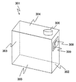
- FIG. 2 is a diagram showing an outline of an outline of a reagent bottle containing a system reagent used in an automatic analyzer as shown in FIG.
- the reagent bottle 301 shown in FIG. 2 is a plastic container having a shape having a long depth with respect to the width.
- each surface shown in FIG. 2 will be described as a front surface 302, a side surface 303, an upper surface 304, and a bottom surface 305 in the insertion direction.
- a columnar screw lid 306 is provided on the upper surface 304 of the reagent bottle 301 at a position where the reagent suction nozzle 400 of the nozzle unit 210 of the reagent bottle installation portion 200, which will be described later, can be inserted.
- a label 308 on which the type of reagent, expiration date, etc. are described is affixed to the front 302 in the insertion direction of the reagent bottle 301.
- An RFID tag 309 is attached to the label 308.
- the RFID tag 309 records information about the system reagent such as reagent type, lot number, expiration date, whether it has been used, and the number of remaining uses.
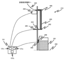
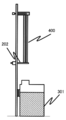
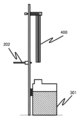
- FIGS. 3 and 4 are diagrams showing a schematic configuration of the reagent bottle installation unit 200 and the nozzle unit 210.
- a plurality of reagent bottle installation portions 200 as shown in FIG. 3 are installed on the back side of the front cover.
- the reagent bottle installation unit 200 is a portion for installing the reagent bottle 301 containing the reagent used for analysis, and is a stopper 202, a stopper drive unit 250, a nozzle unit 210, and an RFID. It has a reader 350. Further, among the control units 131, as a part related to the reagent bottle installation unit 200, there are a reagent determination unit 131a, a stopper drive control unit 131b, and a nozzle drive control unit 131c in the control unit 131.
- the nozzle unit 210 is a unit for joining the supply flow path 220 that connects the place where the reagent is used and the inside of the reagent bottle 301 installed in the reagent bottle installation unit 200 to the reagent bottle 301, and sucks the reagent. It is composed of a nozzle 400 and a nozzle drive unit 450.
- the reagent suction nozzle 400 is a device for joining the supply flow path 220 connecting the location where the reagent is used and the reagent bottle 301 installed in the reagent bottle installation unit 200 to the reagent bottle 301, and is a nozzle drive control unit.
- the nozzle drive unit 450 of a motor or the like under the control of 131c, the reagent suction nozzle 400 is inserted into the reagent in the reagent bottle 301 installed in the reagent bottle installation unit 200, or is removed from the reagent bottle 301. It is configured.
- the reagent suction nozzle 400 is connected to a liquid drive device such as a supply flow path 220 and a syringe (not shown), and the reagent can be supplied from the reagent bottle 301 to a place of use on the device.
- a liquid drive device such as a supply flow path 220 and a syringe (not shown)
- the reagent can be supplied from the reagent bottle 301 to a place of use on the device.
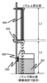
- the stopper 202 is a space between the lower end 402 of the reagent suction nozzle 400 and the reagent bottle 301 as a position on the movement path of the reagent suction nozzle 400 that prevents the reagent suction nozzle 400 from being inserted into the reagent bottle 301. Is located in.
- the stopper 202 is shown in FIGS. 3 and 3 so as to prevent the reagent in the reagent suction nozzle 400 from adhering to the hands of an operator performing the replacement work by any chance when the reagent bottle 301 is replaced.
- the lower end 402 of the reagent suction nozzle 400 and the upper surface side of the stopper 202 are arranged at positions where they come into contact with each other.
- the stopper 202 is arranged at a position where the length L1 from the upper end 404 to the lower end 402 of the reagent suction nozzle 400 and the moving distance L2 of the reagent suction nozzle 400 are equal to each other.
- L1 may be shorter than L2.
- the reagent suction nozzle 400 is joined to the reagent bottle 301, and when it is determined that the reagent is being used, the reagent suction nozzle 400 is arranged at a position where it interferes with the removal even if it is attempted to be removed. There is.
- the material of the stopper 202 is not particularly limited, but it is preferably a material having poor reactivity with the reagent. Further, the rigidity and the like are not particularly limited, but when the lower end 402 of the reagent suction nozzle 400 and the upper surface side of the stopper 202 come into contact with each other, the flexibility is intended to surely prevent the reagent suction nozzle 400 from being deformed. It may be desirable to use a material that has.
- the shape is not particularly limited, and various shapes such as a flat plate can be used.
- the stopper 202 protrudes from the side surface of the reagent bottle installation unit 200 by driving the stopper drive unit 250 such as a motor under the control of the stopper drive control unit 131b, or retracts to the side surface to suck the reagent into the reagent bottle 301. It is configured to prevent the nozzle 400 from being set or removed from the reagent bottle 301.
- the reagent determination unit 131a determines whether or not the reagent bottle 301 installed in the reagent bottle installation unit 200 is appropriate from the reagent information read by the RFID reader 350, and determines the determination result by the stopper drive control unit 131b or the nozzle. Output to the drive control unit 131c.
- stopper drive control unit 131b fixes the stopper 202 except for the timing of replacing the reagent bottle 301, and drives and controls the stopper drive unit 250 so as to prevent the reagent suction nozzle 400 from moving.
- the stopper drive control unit 131b drives the stopper 202 to suck the reagent into the reagent bottle 301 when it is determined from the reagent information that the reagent bottle 301 installed in the reagent bottle installation unit 200 is correct. It is desirable not to interfere with the access of the nozzle 400. Further, when it is not determined that the reagent bottle 301 is correct, it is desirable to prevent the reagent suction nozzle 400 from moving without driving the stopper 202.
- the nozzle drive control unit 131c is a portion that controls the ascending and descending operations of the reagent suction nozzle 400, and the nozzle drive unit 450 is used to fix the reagent suction nozzle 400 except for the timing of replacing the reagent bottle 301. It is desirable to drive and control.
- the nozzle drive control unit 131c drives the reagent suction nozzle 400 when it is determined from the reagent information that the reagent bottle 301 installed in the reagent bottle installation unit 200 is correct, and the reagent bottle 301 is correct. If it is not determined, it is desirable to keep the reagent suction nozzle 400 fixed without driving it.
- the RFID reader 350 is a device that reads the reagent information recorded on the RFID tag 309 attached to the label 308 of the reagent bottle 301, and the front side 302 of the reagent bottle installation unit 200 in the insertion direction of the reagent bottle 301 is inserted.
- the RFID tag 309 is installed in a readable position at the stopped position.
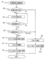
- FIG. 5 is a flowchart at the time of installing the reagent bottle.
- FIG. 6 is a diagram showing the positional relationship between the reagent bottle and the stopper at the time of step S4 in FIG.
- FIG. 7 is a diagram showing the positional relationship between the reagent bottle and the stopper at step S6 in FIG.
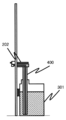
- FIG. 8 is a diagram showing the positional relationship between the reagent bottle and the stopper at the time of step S7 in FIG.
- FIG. 9 is a diagram showing the positional relationship between the reagent bottle and the stopper after step S8 in FIG.
- step S1 When starting the installation of the reagent bottle 301 (FIG. 5, step S1), first, the control unit 131 is set by the reagent bottle installation unit 200 in which the user intends to install the reagent bottle 301 based on the information from the RFID reader 350. It is determined whether or not it is empty (step S2). When it is determined that the reagent bottle setting unit 200 is empty, the process proceeds to step S3. On the other hand, when it is determined that the reagent bottle is not empty, it means that the reagent bottle 301 already in use exists, and the user cannot install the reagent bottle 301. At this time, the process proceeds to step S9.
- the reagent bottle 301 to be installed by the user is placed in the reagent bottle installation unit 200.
- the stopper drive control unit 131b fixes the stopper 202 at the locked position
- the nozzle drive unit 450 fixes the reagent suction nozzle 400 at the raised position.
- the stopper 202 is maintained between the lower end 402 of the reagent suction nozzle 400 and the reagent bottle 301, and the reagent suction nozzle 400 cannot be lowered until the correctness of the installed reagent is confirmed. It is possible to prevent the reagent bottle 301 from being installed and to prevent dripping from the lower end 402 of the reagent suction nozzle 400.
- the information on the RFID tag 309 can be read by the RFID reader 350, so that the RFID reader 350 attempts to read the RFID tag 309 at regular intervals (step). S3).
- control unit 131 determines whether or not the information of the RFID tag 309 can be read by the RFID reader 350, that is, whether or not the reagent bottle 301 is arranged in the reagent bottle installation unit 200 (step S4).
- the process proceeds to step S5.
- the process is returned to step S3 until it is installed, and it waits for it to be installed.
- steps S2 and S3 are not limited to the case where the RFID tag 309 is read by the RFID reader 350, and the determination can be made based on the information from the reagent bottle detection sensor.
- the reagent determination unit 131a determines whether or not the reagent bottle 301 installed by the user is correct (step). S5).
- step S5 When it is determined in step S5 that the reagent bottle 301 installed by the user may be installed, the stopper drive control unit 131b moves the stopper 202 to the standby position and fixes it as shown in FIG. 7 (step S6). ).
- the nozzle drive control unit 131c starts lowering the reagent suction nozzle 400 (step S7), and stops lowering when connected to the reagent bottle 301 as shown in FIG. In this state, the reagent can be sucked.
- the stopper drive control unit 131b moves the stopper 202 to the lock position and fixes it as shown in FIG. 9 (step S8).
- the stopper drive control unit 131b moves the stopper 202 to the lock position and fixes it as shown in FIG. 9 (step S8).
- step S5 it is determined that the reagent should not be installed if the reagent type is different, the expiration date has expired, or the reagent bottle 301 has already been used in another device. Is. Further, even if the information read from the RFID tag 309 deviates from the information that should be read originally, it is determined that the information should not be installed. These determinations are made by the reagent determination unit 131a of the control unit 131 based on the information read from the RFID tag 309 by the RFID reader 350. When the reagent determination unit 131a determines that the reagent bottle 301 to be installed by the user should not be installed, the process proceeds to step S9.
- step S2 If it is determined that the reagent bottle 301 that the user is trying to install should not be installed, it is desirable to notify the user. Therefore, when it is determined in step S2 that the reagent bottle installation unit 200 is not empty, or when it is determined in step S5 that the reagent information is incorrect, the reagent determination unit 131a issues an alarm (step S9), and the user Notify to.
- the notification method includes, for example, turning on the indicator lamp, displaying an alarm on the user interface, and the like.
- the indicator lamp is composed of a button or the like with a built-in LED, which is often arranged in the upper part of the reagent bottle installation unit 200 in the reagent bottle installation unit 200. Depending on how this indicator lamp is lit, it is often used to notify the user of the slot in which the reagent bottle that needs to be replaced is located, or to notify the user that an inappropriate reagent has been installed. .. Further, as described above, this indicator lamp also serves as a button, and when the user presses the reagent bottle 301 when the reagent bottle 301 has been installed in the reagent bottle installation unit 200, the apparatus side has completed the installation of the reagent bottle 301. Can be recognized.
- step S10 the stopper drive control unit 131b fixes the stopper 202 in the locked position (step S10), and ends the process. Therefore, the stopper 202 interferes with the reagent suction nozzle 400 and remains prevented from being lowered to the connection position with the reagent bottle 301. This makes it possible to prevent the user from installing the reagent bottle 301 which should not be installed originally.
- the order of steps S9 and S10 may be reversed.
- the user confirms whether or not the reagent bottle 301 to be installed can be installed before the reagent suction nozzle 400 is connected to the reagent bottle 301.
- the reagent suction nozzle 400 When the reagent suction nozzle 400 is lowered to the connection position, the reagent suction nozzle 400 is already in contact with the reagent in the reagent bottle 301. Therefore, even if the user notices that the reagent bottle 301 is mistaken by the notification from the apparatus, the reagent is mixed through the reagent suction nozzle 400 and the supply flow path 220 beyond the reagent suction nozzle 400. Mixing with reagents that should not be installed may affect analytical performance, so complicated additional operations such as cleaning the reagent suction nozzle 400 and the supply flow path 220 are required before replacement with the correct reagent.
- the reagent determination unit 131a also issue an alarm in this case as well.
- FIG. 10 is a flowchart when the reagent bottle is removed.
- FIG. 11 is a diagram showing the positional relationship between the reagent bottle and the stopper at the time of step S11 in FIG.
- FIG. 12 is a diagram showing the positional relationship between the reagent bottle and the stopper at the time of step S12 in FIG.
- the reagent bottle 301 needs to be replaced, if the reagent bottle 301 is empty, if the reagent has expired, or if the user explicitly instructs the device to replace the reagent, the device. However, there are cases where it is determined that the installed reagents cannot be used based on the quality control results. These determinations are made by the reagent determination unit 131a of the control unit 131.
- control unit 131 When it is determined that the replacement is necessary, the control unit 131 notifies the user of the reagent replacement by blinking the indicator lamp or the like, and as shown in FIG. 11, the stopper drive control unit 131b puts the stopper 202 in the standby position. And fix it (step S11).
- the reagent suction nozzle 400 can be raised, so the nozzle driving unit 450 raises the reagent suction nozzle 400, and after completion, stops and fixes the reagent suction nozzle 400.
- the stopper drive control unit 131b moves the stopper 202 to the locked position and fixes it (step S12). This allows the user to pull out the reagent bottle 301. The user can easily recognize whether or not the reagent bottle 301 can be removed by whether or not the reagent suction nozzle 400 is raised and the stopper 202 is located between the lower end 402 and the reagent bottle 301. be able to.
- step S12 If the reagent bottle 301 remains connected to the connection position within a predetermined time after step S12, there is a possibility that the replacement operation of the reagent bottle 301 has been forgotten, and thus the control unit. It is desirable that 131 issues an alarm.
- the automatic analyzer 1 of the present embodiment described above has a stopper 202, which is arranged on the movement path of the reagent suction nozzle 400 of the nozzle unit 210 and prevents the reagent suction nozzle 400 from being inserted into the reagent bottle 301. I have.
- the stopper 202 located between the reagent suction nozzle 400 and the reagent bottle 301 has the two purposes of erroneously installing the reagent bottle 301 and accidentally removing the reagent bottle 301 while using the reagent.
- This can be realized by the configuration and operation of the drive mechanism, and the device configuration can be simplified while saving space as compared with the conventional case.
- the stopper 202 can prevent the liquid from being received and contacting the user. Also plays.
- the configuration is particularly suitable for a place where a container containing an organic solvent is used as a reagent.
- the stopper 202 is arranged at a position where the length L1 from the upper end 404 to the lower end 402 of the reagent suction nozzle 400 and the moving distance L2 of the reagent suction nozzle 400 are equal to each other, when the reagent bottle 301 is replaced, It is possible to prevent the dripping from the lower end 402 of the reagent suction nozzle 400 by any chance, and it is possible to more reliably prevent the reagent from coming into contact with the user.
- a stopper drive control unit 131b for driving and controlling the stopper 202 is further provided, and the stopper drive control unit 131b fixes the stopper 202 except for the timing of replacing the reagent bottle 301 to prevent the reagent suction nozzle 400 from moving. It is possible to surely prevent the wrong reagent bottle 301 from being installed, and more stable sample analysis becomes possible.
- an RFID reader 350 for reading the reagent information recorded on the RFID tag 309 attached to the reagent bottle 301 is further provided, and the stopper drive control unit 131b uses the stopper 202 when it is determined that the reagent bottle 301 is correct.
- the stopper drive control unit 131b uses the stopper 202 when it is determined that the reagent bottle 301 is correct.
- a nozzle drive control unit 131c for controlling the ascending operation and the descending operation of the reagent suction nozzle 400 is further provided, and the nozzle drive control unit 131c fixes the reagent suction nozzle 400 except for the timing of replacing the reagent bottle 301.
- the nozzle drive control unit 131c fixes the reagent suction nozzle 400 except for the timing of replacing the reagent bottle 301.
- an RFID reader 350 for reading the reagent information recorded on the RFID tag 309 attached to the reagent bottle 301 is further provided, and the nozzle drive control unit 131c is a reagent suction nozzle when it is determined that the reagent bottle 301 is correct.
- the reagent installed when the reagent bottle 301 is installed in the reagent bottle installation unit 200 is appropriate. It is possible to automatically determine whether or not there is a reagent and notify the user, and the burden on the user can be further reduced.
- Detection solution discharge mechanism 120 ... Detection unit 121 ... Detection unit Conveying mechanism 131 ... Control unit 131a ... Reagent judgment unit 131b ... Stopper drive control unit (stopper control unit) 131c ... Nozzle drive control unit (nozzle control unit) 132 ... Recording device 133 ... Display device 134 ... Input device 200 ... Reagent bottle installation unit 202 ... Stopper 210 ... Nozzle unit 220 ... Supply flow path 250 ... Stopper drive unit 301 ... Reagent bottle 302 ... Insertion direction Front 303 ... Side side 304 ... Top surface 305 ... Bottom surface 306 ... Lid 308 ... Label 309 ... RFID tag 350 ... RFID reader 400 ... Reagent suction nozzle 402 ... Lower end 404 ... Upper end 450 ... Nozzle drive unit
Landscapes
- Chemical & Material Sciences (AREA)
- Physics & Mathematics (AREA)
- Health & Medical Sciences (AREA)
- Life Sciences & Earth Sciences (AREA)
- Analytical Chemistry (AREA)
- Biochemistry (AREA)
- General Health & Medical Sciences (AREA)
- General Physics & Mathematics (AREA)
- Immunology (AREA)
- Pathology (AREA)
- Chemical Kinetics & Catalysis (AREA)
- Automatic Analysis And Handling Materials Therefor (AREA)
Abstract
L'invention concerne un dispositif d'analyse automatique (1) comprenant une partie installation de flacon de réactif (200) dans laquelle est installé un flacon de réactif (301) contenant un réactif à utiliser pour une analyse, et une unité buse (210) pour l'assemblage, au flacon de réactif (301), d'un trajet d'écoulement d'alimentation (220) reliant l'emplacement dans lequel le réactif est utilisé à l'intérieur du flacon de réactif (301) installé au niveau de la partie installation de flacon de réactif (200), un bouchon (202) étant disposé sur un trajet de déplacement d'une buse d'aspiration de réactif (400) de l'unité buse (210), qui empêche l'insertion de la buse d'aspiration de réactif (400) dans le flacon de réactif (301). L'invention fournit un dispositif d'analyse automatique configuré pour empêcher un placement de type de réactif erroné et l'élimination d'un réactif de façon inopportune et présentant un espace plus réduit et moins d'éléments.
Priority Applications (4)
| Application Number | Priority Date | Filing Date | Title |
|---|---|---|---|
| CN202180027211.2A CN115398242A (zh) | 2020-04-27 | 2021-02-03 | 自动分析装置 |
| US17/996,602 US20230204612A1 (en) | 2020-04-27 | 2021-02-03 | Automatic analyzer |
| EP21797547.3A EP4145135A4 (fr) | 2020-04-27 | 2021-02-03 | Dispositif d'analyse automatique |
| JP2022518608A JP7281600B2 (ja) | 2020-04-27 | 2021-02-03 | 自動分析装置 |
Applications Claiming Priority (2)
| Application Number | Priority Date | Filing Date | Title |
|---|---|---|---|
| JP2020078414 | 2020-04-27 | ||
| JP2020-078414 | 2020-04-27 |
Publications (1)
| Publication Number | Publication Date |
|---|---|
| WO2021220571A1 true WO2021220571A1 (fr) | 2021-11-04 |
Family
ID=78331921
Family Applications (1)
| Application Number | Title | Priority Date | Filing Date |
|---|---|---|---|
| PCT/JP2021/003959 WO2021220571A1 (fr) | 2020-04-27 | 2021-02-03 | Dispositif d'analyse automatique |
Country Status (5)
| Country | Link |
|---|---|
| US (1) | US20230204612A1 (fr) |
| EP (1) | EP4145135A4 (fr) |
| JP (1) | JP7281600B2 (fr) |
| CN (1) | CN115398242A (fr) |
| WO (1) | WO2021220571A1 (fr) |
Citations (11)
| Publication number | Priority date | Publication date | Assignee | Title |
|---|---|---|---|---|
| JPH05162335A (ja) * | 1991-12-11 | 1993-06-29 | Ricoh Co Ltd | 記録装置及びカートリッジ |
| JPH11271312A (ja) * | 1998-03-23 | 1999-10-08 | Japan Tobacco Inc | 共栓付試験管の自動開閉装置 |
| JP2003246079A (ja) * | 2002-02-25 | 2003-09-02 | Konica Corp | インクジェット記録装置 |
| JP2008096221A (ja) * | 2006-10-10 | 2008-04-24 | Sysmex Corp | 分析装置および試薬収容具 |
| JP2008298590A (ja) * | 2007-05-31 | 2008-12-11 | Olympus Corp | 分析装置および試薬ボトルの管理方法 |
| US20100203573A1 (en) * | 2007-06-12 | 2010-08-12 | Wallac Oy | Automated instrumentation and method for measurements of samples |
| JP2011209207A (ja) * | 2010-03-30 | 2011-10-20 | Sysmex Corp | 検体分析装置 |
| JP2013039732A (ja) * | 2011-08-17 | 2013-02-28 | Seiko Epson Corp | 液体収容容器の誤挿入防止装置、液体収容容器、液体消費装置、および液体収容容器の誤挿入防止方法 |
| JP2014134484A (ja) * | 2013-01-11 | 2014-07-24 | Hitachi High-Technologies Corp | 自動分析装置 |
| JP2016540221A (ja) * | 2013-12-13 | 2016-12-22 | エフ・ホフマン・ラ・ロッシュ・アー・ゲーF. Hoffmann La Roche Ag | 分析機器の試薬容器ホルダ、分析機器の試薬供給システム、及び分析機器 |
| WO2020145389A1 (fr) * | 2019-01-11 | 2020-07-16 | 株式会社日立ハイテク | Analyseur automatisé |
Family Cites Families (3)
| Publication number | Priority date | Publication date | Assignee | Title |
|---|---|---|---|---|
| US7186378B2 (en) * | 2003-07-18 | 2007-03-06 | Dade Behring Inc. | Liquid sampling probe and cleaning fluidics system |
| JP7093188B2 (ja) * | 2018-01-25 | 2022-06-29 | シスメックス株式会社 | 試薬容器、試薬の吸引方法および検体測定装置 |
| WO2019198493A1 (fr) * | 2018-04-12 | 2019-10-17 | 株式会社日立ハイテクノロジーズ | Dispositif d'analyse d'électrolyte |
-
2021
- 2021-02-03 US US17/996,602 patent/US20230204612A1/en active Pending
- 2021-02-03 EP EP21797547.3A patent/EP4145135A4/fr active Pending
- 2021-02-03 JP JP2022518608A patent/JP7281600B2/ja active Active
- 2021-02-03 CN CN202180027211.2A patent/CN115398242A/zh active Pending
- 2021-02-03 WO PCT/JP2021/003959 patent/WO2021220571A1/fr unknown
Patent Citations (11)
| Publication number | Priority date | Publication date | Assignee | Title |
|---|---|---|---|---|
| JPH05162335A (ja) * | 1991-12-11 | 1993-06-29 | Ricoh Co Ltd | 記録装置及びカートリッジ |
| JPH11271312A (ja) * | 1998-03-23 | 1999-10-08 | Japan Tobacco Inc | 共栓付試験管の自動開閉装置 |
| JP2003246079A (ja) * | 2002-02-25 | 2003-09-02 | Konica Corp | インクジェット記録装置 |
| JP2008096221A (ja) * | 2006-10-10 | 2008-04-24 | Sysmex Corp | 分析装置および試薬収容具 |
| JP2008298590A (ja) * | 2007-05-31 | 2008-12-11 | Olympus Corp | 分析装置および試薬ボトルの管理方法 |
| US20100203573A1 (en) * | 2007-06-12 | 2010-08-12 | Wallac Oy | Automated instrumentation and method for measurements of samples |
| JP2011209207A (ja) * | 2010-03-30 | 2011-10-20 | Sysmex Corp | 検体分析装置 |
| JP2013039732A (ja) * | 2011-08-17 | 2013-02-28 | Seiko Epson Corp | 液体収容容器の誤挿入防止装置、液体収容容器、液体消費装置、および液体収容容器の誤挿入防止方法 |
| JP2014134484A (ja) * | 2013-01-11 | 2014-07-24 | Hitachi High-Technologies Corp | 自動分析装置 |
| JP2016540221A (ja) * | 2013-12-13 | 2016-12-22 | エフ・ホフマン・ラ・ロッシュ・アー・ゲーF. Hoffmann La Roche Ag | 分析機器の試薬容器ホルダ、分析機器の試薬供給システム、及び分析機器 |
| WO2020145389A1 (fr) * | 2019-01-11 | 2020-07-16 | 株式会社日立ハイテク | Analyseur automatisé |
Non-Patent Citations (1)
| Title |
|---|
| See also references of EP4145135A4 * |
Also Published As
| Publication number | Publication date |
|---|---|
| JP7281600B2 (ja) | 2023-05-25 |
| JPWO2021220571A1 (fr) | 2021-11-04 |
| EP4145135A4 (fr) | 2024-05-15 |
| CN115398242A (zh) | 2022-11-25 |
| EP4145135A1 (fr) | 2023-03-08 |
| US20230204612A1 (en) | 2023-06-29 |
Similar Documents
| Publication | Publication Date | Title |
|---|---|---|
| US11150256B2 (en) | Reagent management system | |
| EP0593735B1 (fr) | Procede et dispositif d'analyse chimique automatique | |
| US9128072B2 (en) | Apparatus for automatically performing analyses | |
| JP5178830B2 (ja) | 自動分析装置 | |
| US9606133B2 (en) | Specimen analyzer and specimen analyzing method | |
| WO2005008255A1 (fr) | Cartouche pour mesure automatique et dispositif de mesure faisant intervenir celle-ci | |
| WO2021220571A1 (fr) | Dispositif d'analyse automatique | |
| JP5839987B2 (ja) | 自動分析装置 | |
| JP7080391B2 (ja) | 自動分析装置 | |
| US20220065886A1 (en) | Automatic Analyzer | |
| JP6564016B2 (ja) | 自動分析装置 | |
| JP2011007719A (ja) | 自動分析装置 | |
| JP5258090B2 (ja) | 自動分析装置 | |
| US20220341956A1 (en) | Automatic analyzer | |
| JP6724598B2 (ja) | 多機能分注機構を備えた自動分析装置 | |
| WO2023008069A1 (fr) | Dispositif d'analyse automatique et procédé de guidage utilisé dans un dispositif d'analyse automatique |
Legal Events
| Date | Code | Title | Description |
|---|---|---|---|
| 121 | Ep: the epo has been informed by wipo that ep was designated in this application |
Ref document number: 21797547 Country of ref document: EP Kind code of ref document: A1 |
|
| ENP | Entry into the national phase |
Ref document number: 2022518608 Country of ref document: JP Kind code of ref document: A |
|
| NENP | Non-entry into the national phase |
Ref country code: DE |
|
| ENP | Entry into the national phase |
Ref document number: 2021797547 Country of ref document: EP Effective date: 20221128 |